EP4579199A2 - Dynamic calibration compensation for flow meter - Google Patents
Dynamic calibration compensation for flow meter Download PDFInfo
- Publication number
- EP4579199A2 EP4579199A2 EP25162703.0A EP25162703A EP4579199A2 EP 4579199 A2 EP4579199 A2 EP 4579199A2 EP 25162703 A EP25162703 A EP 25162703A EP 4579199 A2 EP4579199 A2 EP 4579199A2
- Authority
- EP
- European Patent Office
- Prior art keywords
- flow meter
- beverage brewing
- beverage
- relationship
- calibration
- Prior art date
- Legal status (The legal status is an assumption and is not a legal conclusion. Google has not performed a legal analysis and makes no representation as to the accuracy of the status listed.)
- Pending
Links
Images


Classifications
-
- A—HUMAN NECESSITIES
- A47—FURNITURE; DOMESTIC ARTICLES OR APPLIANCES; COFFEE MILLS; SPICE MILLS; SUCTION CLEANERS IN GENERAL
- A47J—KITCHEN EQUIPMENT; COFFEE MILLS; SPICE MILLS; APPARATUS FOR MAKING BEVERAGES
- A47J31/00—Apparatus for making beverages
- A47J31/04—Coffee-making apparatus with rising pipes
- A47J31/057—Coffee-making apparatus with rising pipes with water container separated from beverage container, the hot water passing the filter only once i.e. classical type of drip coffee makers
-
- A—HUMAN NECESSITIES
- A47—FURNITURE; DOMESTIC ARTICLES OR APPLIANCES; COFFEE MILLS; SPICE MILLS; SUCTION CLEANERS IN GENERAL
- A47J—KITCHEN EQUIPMENT; COFFEE MILLS; SPICE MILLS; APPARATUS FOR MAKING BEVERAGES
- A47J31/00—Apparatus for making beverages
- A47J31/10—Coffee-making apparatus, in which the brewing vessel, i.e. water heating container, is placed above or in the upper part of the beverage containers i.e. brewing vessel; Drip coffee-makers with the water heating container in a higher position than the brewing vessel
-
- A—HUMAN NECESSITIES
- A47—FURNITURE; DOMESTIC ARTICLES OR APPLIANCES; COFFEE MILLS; SPICE MILLS; SUCTION CLEANERS IN GENERAL
- A47J—KITCHEN EQUIPMENT; COFFEE MILLS; SPICE MILLS; APPARATUS FOR MAKING BEVERAGES
- A47J31/00—Apparatus for making beverages
- A47J31/44—Parts or details or accessories of beverage-making apparatus
-
- A—HUMAN NECESSITIES
- A47—FURNITURE; DOMESTIC ARTICLES OR APPLIANCES; COFFEE MILLS; SPICE MILLS; SUCTION CLEANERS IN GENERAL
- A47J—KITCHEN EQUIPMENT; COFFEE MILLS; SPICE MILLS; APPARATUS FOR MAKING BEVERAGES
- A47J31/00—Apparatus for making beverages
- A47J31/44—Parts or details or accessories of beverage-making apparatus
- A47J31/52—Alarm-clock-controlled mechanisms for coffee- or tea-making apparatus ; Timers for coffee- or tea-making apparatus; Electronic control devices for coffee- or tea-making apparatus
-
- G—PHYSICS
- G01—MEASURING; TESTING
- G01F—MEASURING VOLUME, VOLUME FLOW, MASS FLOW OR LIQUID LEVEL; METERING BY VOLUME
- G01F25/00—Testing or calibration of apparatus for measuring volume, volume flow or liquid level or for metering by volume
- G01F25/10—Testing or calibration of apparatus for measuring volume, volume flow or liquid level or for metering by volume of flowmeters
Definitions
- This application relates to a flow meter, and more specifically to dynamic calibration of a flow meter of a beverage brewing apparatus.
- a plurality of factors influence the flavor when brewing a cup of coffee, including the quantity of coffee, the quantity of water, the temperature of the water, and the contact time between the coffee and the water.
- a flow meter is used to monitor a volume of water delivered to the coffee.
- the flow meter generally includes a rotor having opposing polarity magnets embedded therein.
- the rotor is configured to spin about a central axis as water flows there through.
- these magnets pass a Hall Effect sensor, functioning as a switch that it activated and deactivated by the magnetic fields of the magnets. For every rotation of the rotor, a high and low signal is observed by the Hall Effect sensor.
- a high quality flow meter may be accurate to within .5%, meaning that each toggle in the flow meter signal can be related directly to a volume of water. For example, if a system intends to deliver 1000mL of water and the flow meter is calibrated to deliver .5mL per pulse, a controller will simply track the total number of pulses until 2000 pulses have been observed. Accuracy of these systems is dependent upon the linearity of the flow meter over the operating range of the system. In order to control the operation conditions of a beverage brewing system a pump is typically used to control the flow rate.
- the flow rate of fluid through the flow meter may change based on variates in the wall voltage, boiler power, boiler efficiency, water temperature, or other influencing factors. As these factors shift the flow rate away from the nominal target rate, the performance of the flow meter similarly shifts, thereby compromising the accuracy of the system.
- a beverage brewing apparatus including a reservoir, a brew basket configured to container a flavorant for preparing a brewed beverage, and a heating mechanism fluidly coupled to the reservoir and the brew basket.
- a flow meter is configured to measure a volume of fluid supplied from the reservoir to the brew bask. The flow meter is configured to calibrate dynamically in response to at least one operating parameter of the beverage brewing apparatus.
- the at least one operating parameter includes voltage of the beverage system.
- a method of dynamically calibrating a flow meter including identifying a relationship between calibration variance and pulse rate of the flow meter to form an advanced logic calibration and applying the advanced logic calibration to the flow meter.
- the advanced logic calibration is applied to each pulse observed by the flow meter.
- the relationship between calibration variance and pulse rate is generally linear.
- the relationship between calibration variance and pulse rate of the flow meter is determined using data collected during operation of a beverage brewing apparatus.
- the advanced calibration logic is based on data collected from a plurality of beverage brewing apparatuses.
- an average pulse rate per time interval is calculated for the plurality of beverage brewing apparatuses.
- the advanced logic calibration is then applied to the average pulse rate.
- an operating condition of at least one of the plurality of beverage brewing apparatuses is different.
- the programmed volume of fluid to be provided was 1281 mL. As shown in the table above, the difference between the programmed volume and the measured volume was between -1.7% and 5.5% for each of the various test runs. Through this experimentation, it has been determined that the accuracy of the flow meter 32 fluctuates with the flow rate when the voltage applied to the system 20 is varied. A graph comparing the flow rate (mL/s) and Volume Variation of the data of Table 1 is illustrated in FIG. 2 .
- Fig. 3 indicates the recorded pulse rates on a moving average basis, or more specifically, the number of pulses recorded in a set time period. Although a time period of 2 seconds was used in the illustrated, non-limiting embodiment, any length of time sufficient to provide an accurate representation of the data with a minimized delay is acceptable. Using this pulse information, the average flow rate can be tracked and converted into a calibration scaling factor.
- Table 2 An example of the data recorded for a 50 pulse section of the graph of FIG. 3 is shown in Table 2 below.
- FIGS. 4 and 5 By analyzing this data relative to voltage and temperature ranges, two graphs, shown in FIGS. 4 and 5 , were generated to identify the relationship between flow rate and calibration variance ( FIG. 4 ), as well as pulse rate and calibration variance ( FIG. 5 ).
- the graph of pulse rate vs. calibration variance is configured to indicate the variation in the calibration coefficient based on how fast the flow meter 32 is rotating.
- the relationship presented in FIG. 5 directly correlates a signal sent from the flow meter 32 and received by a controller of the brewing system 20 with a calibration variation.
- the calibration coefficient can be used to determine a total volume delivered by the flow meter 32 with each pulse.
- This scaling factor can be applied to a recorded data set to more accurately predict the volume of fluid delivered by a flow meter 32 .
- the graph of FIG. 7 compares the volume of fluid delivered by a flow meter 32 using the fixed calibration logic, and the volume of fluid delivered by a flow meter 32 using the scaling factor of the advanced calibration logic relative to a target volume.
- the flow meter 32 using the advanced calibration logic is substantially more accurate relative to the target volume.
- FIGS. 4 and 5 compare calibration variance, a relationship between the flow rate and the average pulse rate may be established.
- a graph illustrating the relationship between the average flow rate and the average pulse rate is illustrated in FIG. 6 . This relationship enables an average pulse rate to be approximated for test runs on where only volume and time were recorded.
- Tables 1 and 2 and FIGS. 2-7 are representative of a single beverage brewing apparatus 20. Although each unit of a mass produced beverage brewing apparatus 20 is formed substantially identically, differences in performance may occur due to variances in manufacturing, assembly, or usage conditions. To create a universal calibration coefficient applicable to all of the units of a mass produced beverage brewing apparatus 20, similar experimentation is performed using a plurality of units of the beverage brewing apparatus 20 to create an approximation of the average pulse rates based on average flow rates thereof, as shown in FIG. 6 .
- FIG. 8 which compares average pulse rate to volumetric variance, clearly shows that in the absence of advanced calibration logic, the volume of water delivered via a flow meter 32 may drastically increase as the power to the system varies. It is also observed that a nominal calibration coefficient is centered about 13.4 average pulses, which corresponds to room temperature water being brewed using 120V of power.
- this scaling value to the flow meter calibration coefficient allows the volume of fluid measured by the flow meter 32 to adjust dynamically during operation of the apparatus 20 to such that a more accurate amount of water is consistently provided for brewing a beverage.
Landscapes
- Engineering & Computer Science (AREA)
- Food Science & Technology (AREA)
- Physics & Mathematics (AREA)
- Fluid Mechanics (AREA)
- General Physics & Mathematics (AREA)
- Apparatus For Making Beverages (AREA)
Abstract
Description
- This application relates to a flow meter, and more specifically to dynamic calibration of a flow meter of a beverage brewing apparatus.
- A plurality of factors influence the flavor when brewing a cup of coffee, including the quantity of coffee, the quantity of water, the temperature of the water, and the contact time between the coffee and the water. In many systems configured to brew a beverage such as coffee, a flow meter is used to monitor a volume of water delivered to the coffee. The flow meter generally includes a rotor having opposing polarity magnets embedded therein. The rotor is configured to spin about a central axis as water flows there through. As the flow meter rotates, these magnets pass a Hall Effect sensor, functioning as a switch that it activated and deactivated by the magnetic fields of the magnets. For every rotation of the rotor, a high and low signal is observed by the Hall Effect sensor.
- Under constant conditions, a high quality flow meter may be accurate to within .5%, meaning that each toggle in the flow meter signal can be related directly to a volume of water. For example, if a system intends to deliver 1000mL of water and the flow meter is calibrated to deliver .5mL per pulse, a controller will simply track the total number of pulses until 2000 pulses have been observed. Accuracy of these systems is dependent upon the linearity of the flow meter over the operating range of the system. In order to control the operation conditions of a beverage brewing system a pump is typically used to control the flow rate. However, in systems where the operating conditions are not controlled, the flow rate of fluid through the flow meter may change based on variates in the wall voltage, boiler power, boiler efficiency, water temperature, or other influencing factors. As these factors shift the flow rate away from the nominal target rate, the performance of the flow meter similarly shifts, thereby compromising the accuracy of the system.
- According to one embodiment, a beverage brewing apparatus is provided including a reservoir, a brew basket configured to container a flavorant for preparing a brewed beverage, and a heating mechanism fluidly coupled to the reservoir and the brew basket. A flow meter is configured to measure a volume of fluid supplied from the reservoir to the brew bask. The flow meter is configured to calibrate dynamically in response to at least one operating parameter of the beverage brewing apparatus.
- In addition to one or more of the features described above, or as an alternative, in further embodiments the at least one operating parameter includes voltage of the beverage system.
- In addition to one or more of the features described above, or as an alternative, in further embodiments the at least one operating parameter includes a temperature of the fluid.
- According to another embodiment, a method of dynamically calibrating a flow meter is provided including identifying a relationship between calibration variance and pulse rate of the flow meter to form an advanced logic calibration and applying the advanced logic calibration to the flow meter.
- In addition to one or more of the features described above, or as an alternative, in further embodiments the advanced logic calibration is applied to each pulse observed by the flow meter.
- In addition to one or more of the features described above, or as an alternative, in further embodiments the relationship between calibration variance and pulse rate is generally linear.
- In addition to one or more of the features described above, or as an alternative, in further embodiments the relationship between calibration variance and pulse rate of the flow meter is determined using data collected during operation of a beverage brewing apparatus.
- In addition to one or more of the features described above, or as an alternative, in further embodiments the advanced calibration logic is based on data collected from a plurality of beverage brewing apparatuses.
- In addition to one or more of the features described above, or as an alternative, in further embodiments the method includes identifying a relationship between calibration variance and flow rate of a fluid through the flow meter to form an advanced logic calibration. A relationship between between flow rate and pulse rate is then determined.
- In addition to one or more of the features described above, or as an alternative, in further embodiments an average pulse rate per time interval is calculated for the plurality of beverage brewing apparatuses. The advanced logic calibration is then applied to the average pulse rate.
- In addition to one or more of the features described above, or as an alternative, in further embodiments an operating condition of at least one of the plurality of beverage brewing apparatuses is different.
- The accompanying drawings incorporated in and forming a part of the specification embodies several aspects of the present disclosure and, together with the description, serves to explain the principles of the disclosure. In the drawings:
-
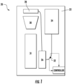
FIG. 1 is a schematic diagram of an example of a beverage brewing apparatus; -
FIG. 2 is a graph comparing flow rate and volumetric variation measured for a single beverage brewing apparatus; -
FIG. 3 is a graph illustrating the pulses of a flow meter over a set period of time for a single beverage brewing apparatus; -
FIG. 4 is a graph comparing flow rate and calibration variation measured for a single beverage brewing apparatus; -
FIG. 5 is a graph comparing pulse rate and calibration variation measured for a single beverage brewing apparatus -
FIG. 6 is a graph comparing flow rate and pulse rate based on the measured data of a single beverage brewing apparatus; -
FIG. 7 is a graph representing a volume of fluid delivered by a flow meter having fixed logic and a flow meter having advanced calibration logic compared to a target volume; and -
FIG. 8 is a graph comparing pulse rate to the volume variance for a plurality of beverage brewing apparatuses having varying operational parameters. - The detailed description explains embodiments of the disclosure, together with advantages and features, by way of example with reference to the drawings.
- With reference now to
FIG. 1 , a schematic diagram of an example of a basic automaticbeverage brewing apparatus 20, such as a coffee maker for example, is illustrated in more detail. The apparatus includes ahousing 22, areservoir 24, aheating mechanism 26, ashower head 28, and a brew basket 30. Thereservoir 24,heating mechanism 26,showerhead 28, and brew basket 30 are arranged sequentially in fluid communication. Upon activation of theapparatus 20, water or another fluid stored within the reservoir 30, is provided to aheating mechanism 26. After being heated to a desired temperature, the water is provided to theshower head 28. The shower head is aligned with and disposed vertically above the brew basket. The water is configured to flow through one or more holes formed in the shower head onto coffee grounds or another flavorant contained within the brew basket. The fluid containing a portion of the flavorant, is provided to acontainer 31 via an outlet formed near the bottom of the brew basket. - As illustrated in
FIG. 1 , aflow meter 32 may be arranged within a conduit extending between thewater reservoir 24 and theheating mechanism 26. As shown, thewater reservoir 24 may be vertically aligned with theflow meter 32 such that water is fed to thesystem 20, and more specifically to theflow meter 32, by gravity. Theflow meter 32 is configured to monitor an amount of water passing there through, which is generally indicative of the amount of water provided to theshower head 28. Various types of flow meters are within the scope of the disclosure. For example, theflow meter 32 may be a rotatable paddle wheel where each rotation generates a signal indicating that a known amount of water has passed through the flow meter 92. Further detail on this type ofbeverage brewing apparatus 20 is disclosed inUS. Patent Appl. Serial No. 14/568,471 filed on December 12, 2014 US. Patent Appl. Serial No. 14/812,731 filed on July 29, 2015 beverage brewing apparatus 20 described herein is intended as an example only, and any other apparatus including a flow meter is within the scope of the invention. - With reference now to
FIGS. 2 - 8 , a software algorithm for dynamically calibrating theflow meter 32 based on the operational parameters of thebeverage brewing system 20, also referred to herein as "advanced calibration logic", is described in more detail. Thebrewing apparatus 20 is configured to provide a known volume of fluid when operated in a first mode. To generate an equation to be applied to operation of theflow meter 32 as advanced calibration logic, the relationship between pulse rate and the calibration variance of theflow meter 32 must be identified. - By measuring the actual volume of fluid provided and by monitoring one or more operational parameters of the
system 20, a relationship between operation of theflow meter 32 and one or more parameters of thesystem 20 may be determined. For example, as shown in Table 1 illustrated below, the voltage provided to theflow meter 32 and the time required to provide the desired volume of fluid are measured.Table 1 - Recorded Measurements from Test Unit 1 Voltage Volume Delivered vs. Target Effective Time (s) Flow Rate 128 1267 -1.1% 305 4.15 128 1259 -1.7% 303 4.16 120 1294 1.0% 340 3.81 120 1291 0.8% 337 3.83 112 1310 2.3% 382 3.43 112 1323 3.3% 386 3.43 104 1351 5.5% 447 3.02 104 1348 5.2% 451 2.99 - In the illustrated, non-limiting embodiment, the programmed volume of fluid to be provided was 1281 mL. As shown in the table above, the difference between the programmed volume and the measured volume was between -1.7% and 5.5% for each of the various test runs. Through this experimentation, it has been determined that the accuracy of the
flow meter 32 fluctuates with the flow rate when the voltage applied to thesystem 20 is varied. A graph comparing the flow rate (mL/s) and Volume Variation of the data of Table 1 is illustrated inFIG. 2 . - During operation, the
system 20 is only configured to observe pulses generated by theflow meter 32 and has no knowledge of flow rate.Fig. 3 indicates the recorded pulse rates on a moving average basis, or more specifically, the number of pulses recorded in a set time period. Although a time period of 2 seconds was used in the illustrated, non-limiting embodiment, any length of time sufficient to provide an accurate representation of the data with a minimized delay is acceptable. Using this pulse information, the average flow rate can be tracked and converted into a calibration scaling factor. An example of the data recorded for a 50 pulse section of the graph ofFIG. 3 is shown in Table 2 below.Table 2: Time Array of recorded pulses Array Element Pulse Time Array Element Pulse Time Array Element Pulse Time Array Element Pulse Time Array Element Pulse Time 0 8801 10 9946 20 11001 30 5703 40 6852 1 8966 11 10053 21 11109 31 5805 41 7008 2 9086 12 10160 22 11209 32 5901 42 7164 3 9225 13 10284 23 11321 33 6008 43 7362 4 9329 14 10391 24 11427 34 6111 44 7581 5 9444 15 10501 25 5252 35 6226 45 7864 6 9542 16 10604 26 5335 36 6338 46 8115 7 9642 17 10705 27 5428 37 6463 47 8337 8 9744 18 10800 28 5514 38 6584 48 8513 9 9851 19 10904 29 5611 39 6720 49 8665 - By analyzing this data relative to voltage and temperature ranges, two graphs, shown in
FIGS. 4 and5 , were generated to identify the relationship between flow rate and calibration variance (FIG. 4 ), as well as pulse rate and calibration variance (FIG. 5 ). The graph of pulse rate vs. calibration variance is configured to indicate the variation in the calibration coefficient based on how fast theflow meter 32 is rotating. - The relationship presented in
FIG. 5 directly correlates a signal sent from theflow meter 32 and received by a controller of thebrewing system 20 with a calibration variation. As a result, the calibration coefficient can be used to determine a total volume delivered by theflow meter 32 with each pulse. In this embodiment, for every pulse fewer recorded per 2-second averaging window, the calibration would increase by 2.64% as noted by the linear regression through the data set. In this embodiment, the nominal calibration coefficient, corresponding to a volume of water passing through the flow meter, was specified to be 0.656 milliliters of fluid per pulse under nominal conditions. If a pulse were to exist whereby the average number of pulses recorded in a 2-second window was 10.0, the scaling factor would thus be calculated as:
flow meter 32 until the total volume delivered has reached a prescribed target volume, in this embodiment 1281 mL. - This scaling factor can be applied to a recorded data set to more accurately predict the volume of fluid delivered by a
flow meter 32 . For example, the graph ofFIG. 7 compares the volume of fluid delivered by aflow meter 32 using the fixed calibration logic, and the volume of fluid delivered by aflow meter 32 using the scaling factor of the advanced calibration logic relative to a target volume. As is clearly illustrated, theflow meter 32 using the advanced calibration logic is substantially more accurate relative to the target volume. - Because both of the graphs in
FIGS. 4 and5 compare calibration variance, a relationship between the flow rate and the average pulse rate may be established. A graph illustrating the relationship between the average flow rate and the average pulse rate is illustrated inFIG. 6 . This relationship enables an average pulse rate to be approximated for test runs on where only volume and time were recorded. - The data illustrated in Tables 1 and 2 and
FIGS. 2-7 is representative of a singlebeverage brewing apparatus 20. Although each unit of a mass producedbeverage brewing apparatus 20 is formed substantially identically, differences in performance may occur due to variances in manufacturing, assembly, or usage conditions. To create a universal calibration coefficient applicable to all of the units of a mass producedbeverage brewing apparatus 20, similar experimentation is performed using a plurality of units of thebeverage brewing apparatus 20 to create an approximation of the average pulse rates based on average flow rates thereof, as shown inFIG. 6 . - By applying similar transformations to the data collected from a plurality of units, for example 14 units, it was determined that although a spread in performance exists, most of the units followed a predictable trend illustrated in
FIG. 8. FIG. 8 , which compares average pulse rate to volumetric variance, clearly shows that in the absence of advanced calibration logic, the volume of water delivered via aflow meter 32 may drastically increase as the power to the system varies. It is also observed that a nominal calibration coefficient is centered about 13.4 average pulses, which corresponds to room temperature water being brewed using 120V of power. However, because the voltage range provided across the United States extends from between 107V to 128V and becausemost brewing apparatuses 20 instruct an operator to use cold water, it is desirable to set the neutral point of operation at averaged conditions assuming a power supply of 117V and a cold water temperature of about 3-5°C. Under these conditions, the average pulse count is approximately 10.2 pulses per 2 seconds. By adjusting the equation of the linear regression line ofFIG. 8 to account for this shift in the average conditions, the resultant dynamic flow meter calibration scaling value is:
- Application of this scaling value to the flow meter calibration coefficient allows the volume of fluid measured by the
flow meter 32 to adjust dynamically during operation of theapparatus 20 to such that a more accurate amount of water is consistently provided for brewing a beverage. - All references, including publications, patent applications, and patents cited herein are hereby incorporated by reference to the same extent as if each reference were individually and specifically indicated to be incorporated by reference and were set forth in its entirety herein.
- The use of the terms "a" and "an" and "the" and similar referents in the context of describing the disclosure (especially in the context of the following claims) is to be construed to cover both the singular and the plural, unless otherwise indicated herein or clearly contradicted by context. The terms "comprising," "having," "including," and "containing" are to be construed as open-ended terms (i.e., meaning "including, but not limited to,") unless otherwise noted. Recitation of ranges of values herein are merely intended to serve as a shorthand method of referring individually to each separate value falling within the range, unless otherwise indicated herein, and each separate value is incorporated into the specification as if it were individually recited herein. All methods described herein can be performed in any suitable order unless otherwise indicated herein or otherwise clearly contradicted by context. The use of any and all examples, or exemplary language (e.g., "such as") provided herein, is intended merely to better illuminate the disclosure and does not pose a limitation on the scope of the disclosure unless otherwise claimed. No language in the specification should be construed as indicating any non-claimed element as essential to the practice of the disclosure.
- Exemplary embodiments of this disclosure are described herein, including the best mode known to the inventors for carrying out the disclosure. Variations of those embodiments may become apparent to those of ordinary skill in the art upon reading the foregoing description. The inventors expect skilled artisans to employ such variations as appropriate, and the inventors intend for the disclosure to be practiced otherwise than as specifically described herein. Accordingly, this disclosure includes all modifications and equivalents of the subject matter recited in the claims appended hereto as permitted by applicable law. Moreover, any combination of the above-described elements in all possible variations thereof is encompassed by the disclosure unless otherwise indicated herein or otherwise clearly contradicted by context.
- The following examples are disclosed.
- Example 1. A beverage brewing apparatus, comprising:
- a reservoir;
- a brew basket configured to contain a flavorant for preparing a brewed beverage;
- a heating mechanism fluidly coupled to the reservoir and the brew basket; and
- a flow meter configured to measure a volume of fluid supplied from the reservoir to said brew basket, wherein said flow meter is configured to calibrate dynamically in response to at least one operating parameter of said beverage brewing apparatus.
- Example 2. The beverage system according to Example 1, wherein the at least one operating parameter includes voltage of the beverage system.
- Example 3. The beverage system according to Example 1, wherein the at least one operating parameter includes a temperature of the fluid.
- Example 4. A method of dynamically calibrating a flow meter, comprising:
- identifying a relationship between calibration variance and pulse rate of the flow meter to form an advanced logic calibration; and
- applying the advanced logic calibration to the flow meter.
- Example 5. The method according to Example 4, wherein the advanced logic calibration is applied to each pulse observed by the flow meter.
- Example 6. The method according to Example 4, wherein the relationship between calibration variance and pulse rate is generally linear.
- Example 7. The method according to Example 4, wherein the relationship between calibration variance and pulse rate of the flow meter is determined based on data collected during operation of a beverage brewing apparatus.
- Example 8. The method according to Example 4, wherein the advanced calibration logic is based on data collected from a plurality of beverage brewing apparatuses.
- Example 9. The method according to Example 8, further comprising:
- identifying a relationship between calibration variance and flow rate of a fluid through the flow meter to form an advanced logic calibration; and
- determining a relationship between flow rate and pulse rate.
- Example 10. The method according to Example 9, further comprising:
- calculating an average pulse rate per time interval for the plurality of beverage brewing apparatuses; and
- applying the advanced logic calibration to the average pulse rate.
- Example 11. The method according to Example 8, wherein an operating condition of at least one of the plurality of beverage brewing apparatuses is different.
Claims (10)
- A method of dynamically calibrating a flow meter (32) of a beverage brewing apparatus (20), the method comprising:determining a relationship between an actual amount of water passing through the flow meter (32) and a signal of the flow meter (32) indicating a known amount of water passing through the flow meter (32) during at least one operating condition associated with preparation of a brewed beverage using the beverage brewing apparatus (20); anddetermining the actual amount of water passing through the flow meter (32) based on the determined relationship during the preparation of the brewed beverage.
- The method according to claim 1, wherein the relationship is applied to the signal of the flow meter (32).
- The method according to claim 1, wherein the relationship is linear.
- The method according to claim 1, wherein the relationship is determined based on data collected during the at least one operation condition of the beverage brewing apparatus (20).
- The method according to claim 1, wherein the relationship is based on data collected from a plurality of beverage brewing apparatuses (20).
- The method according to claim 5, further comprising:
determining a calibration coefficient based on the relationship to form a calibration algorithm. - The method according to claim 6, wherein the signal comprises a pulse rate characterizing a plurality of pulses generated by respective flow meters (32) of the plurality of beverage brewing apparatuses (20) in a period of time during preparation of brewed beverages using each of the plurality of beverage brewing apparatuses (20), the method further comprising:calculating an average pulse rate generated by the respective flow meters (32) for each of the plurality of beverage brewing apparatuses (20) in the period of time; andapplying the calibration algorithm to the average pulse rate.
- The method according to claim 7, wherein the calibration algorithm is applied to an average pulse rate of a plurality of pulses generated by the flow meter (32) during the at least one operating condition associated with the preparation of the brewed beverage using the beverage brewing apparatus (20).
- The method according to claim 8, wherein the calibration algorithm is applied to each pulse of the plurality of pulses generated by the flow meter (32) during the at least one operating condition associated with the preparation of the brewed beverage using the beverage brewing apparatus (20) until the known amount of water reaches a predetermined volume.
- The method according to claim 5, wherein a first temperature of a first actual amount of water passing through a first flow meter (32) of a first beverage brewing apparatus (20) of the plurality of beverage brewing apparatuses is different than a second temperature of a second actual amount of water passing through a second flow meter (32) of a second beverage brewing apparatus (20) of the plurality of beverage brewing apparatuses.
Applications Claiming Priority (3)
| Application Number | Priority Date | Filing Date | Title |
|---|---|---|---|
| US14/887,562 US10156468B2 (en) | 2015-10-20 | 2015-10-20 | Dynamic calibration compensation for flow meter |
| EP16784728.4A EP3364824B1 (en) | 2015-10-20 | 2016-10-13 | Dynamic calibration compensation for flow meter |
| PCT/US2016/056744 WO2017069994A1 (en) | 2015-10-20 | 2016-10-13 | Dynamic calibration compensation for flow meter |
Related Parent Applications (1)
| Application Number | Title | Priority Date | Filing Date |
|---|---|---|---|
| EP16784728.4A Division EP3364824B1 (en) | 2015-10-20 | 2016-10-13 | Dynamic calibration compensation for flow meter |
Publications (2)
| Publication Number | Publication Date |
|---|---|
| EP4579199A2 true EP4579199A2 (en) | 2025-07-02 |
| EP4579199A3 EP4579199A3 (en) | 2025-09-03 |
Family
ID=57178557
Family Applications (2)
| Application Number | Title | Priority Date | Filing Date |
|---|---|---|---|
| EP16784728.4A Active EP3364824B1 (en) | 2015-10-20 | 2016-10-13 | Dynamic calibration compensation for flow meter |
| EP25162703.0A Pending EP4579199A3 (en) | 2015-10-20 | 2016-10-13 | Dynamic calibration compensation for flow meter |
Family Applications Before (1)
| Application Number | Title | Priority Date | Filing Date |
|---|---|---|---|
| EP16784728.4A Active EP3364824B1 (en) | 2015-10-20 | 2016-10-13 | Dynamic calibration compensation for flow meter |
Country Status (7)
| Country | Link |
|---|---|
| US (1) | US10156468B2 (en) |
| EP (2) | EP3364824B1 (en) |
| JP (1) | JP2018534985A (en) |
| KR (1) | KR102603962B1 (en) |
| CN (1) | CN108430281B (en) |
| AU (1) | AU2016340808B2 (en) |
| WO (1) | WO2017069994A1 (en) |
Families Citing this family (6)
| Publication number | Priority date | Publication date | Assignee | Title |
|---|---|---|---|---|
| CN107687959A (en) * | 2017-11-01 | 2018-02-13 | 中山市华源电气设备有限公司 | Testing device and testing method for powder-brewing beverage machine |
| CN109269603B (en) * | 2018-10-31 | 2021-02-26 | 四川泛华航空仪表电器有限公司 | Coefficient calibration method based on flow sensor |
| CN115137209B (en) * | 2021-03-31 | 2025-04-22 | 汉美驰品牌有限公司 | Beverage making machines |
| FR3127280B1 (en) * | 2021-09-20 | 2023-09-15 | Seb Sa | Method for calibrating a weight sensor arranged on the tank of a beverage dispensing machine |
| CN116687210B (en) * | 2022-02-15 | 2025-08-08 | 佛山市顺德区美的饮水机制造有限公司 | Flow rate confirmation method, control method and device, storage medium and water treatment device |
| DE102022128366A1 (en) | 2022-10-26 | 2024-05-02 | Endress+Hauser Flowtec Ag | Method for adjusting and/or calibrating a flow meter and flow meter |
Family Cites Families (30)
| Publication number | Priority date | Publication date | Assignee | Title |
|---|---|---|---|---|
| US4651632A (en) | 1985-12-13 | 1987-03-24 | Wuerttembergische Metallwarenfabrik Ag. | Coffee percolator |
| JP3349606B2 (en) * | 1994-11-09 | 2002-11-25 | 東京瓦斯株式会社 | Gas meter flow compensator |
| GB2295896A (en) * | 1994-12-08 | 1996-06-12 | Sgs Redwood Ltd | Calibration of flowmeters |
| US5555190A (en) * | 1995-07-12 | 1996-09-10 | Micro Motion, Inc. | Method and apparatus for adaptive line enhancement in Coriolis mass flow meter measurement |
| CN1184931A (en) * | 1996-12-11 | 1998-06-17 | 唐秀家 | Method and apparatus for detecting and positioning leakage of fluid transferring pipeline |
| JP4208039B2 (en) * | 1997-10-02 | 2009-01-14 | 澁谷工業株式会社 | Flow rate filling device |
| US6097786A (en) * | 1998-05-18 | 2000-08-01 | Schlumberger Technology Corporation | Method and apparatus for measuring multiphase flows |
| US6845704B2 (en) * | 2001-02-20 | 2005-01-25 | Food Equipment Technologies Company, Inc. | Beverage making system with flow meter measurement control and method |
| US7212928B2 (en) * | 2002-09-06 | 2007-05-01 | Invensys Systems, Inc. | Multi-measurement vortex flow meter |
| US7503253B2 (en) * | 2004-02-09 | 2009-03-17 | Bunn-O-Matic Corporation | Apparatus, system and method for infusing a pre-packaged pod |
| US7089849B2 (en) * | 2004-05-06 | 2006-08-15 | Electrical And Electronics Limited | Single/multiple beverage machine |
| WO2005107540A1 (en) * | 2004-05-06 | 2005-11-17 | Electrical And Electronics Limited | Single/multiple beverage machine |
| WO2006045039A2 (en) * | 2004-10-15 | 2006-04-27 | Bunn-O-Matic Corporation | Brewer calibration system |
| US7677158B2 (en) * | 2004-11-03 | 2010-03-16 | Sunbeam Products, Inc. | Beverage maker having brewing chamber adapted to receive coffee pods or loose coffee |
| US8726789B2 (en) * | 2005-10-11 | 2014-05-20 | Bunn-O-Matic Corporation | Air pump operated brewer system and method |
| US20070119308A1 (en) * | 2005-11-16 | 2007-05-31 | Glucksman Dov Z | Hot beverage apparatus |
| JP4606358B2 (en) * | 2006-03-20 | 2011-01-05 | 東洋紡エンジニアリング株式会社 | Automatic milking device |
| CN101105407A (en) * | 2007-04-10 | 2008-01-16 | 浙江富马仪表有限公司 | Air energy-storage volume tube liquid runoff calibration device |
| CN101868420B (en) * | 2007-09-06 | 2014-02-12 | 德卡产品有限公司 | Beverage Dispensing System |
| US8225708B2 (en) * | 2007-10-12 | 2012-07-24 | Food Equipment Technologies Company Inc. | Multi-beverage brewer with on-demand variable brew water temperature and method |
| EP2107242B1 (en) * | 2008-04-01 | 2011-12-28 | Societe Des Produits Nestle S.A. | Beverage dispensing apparatus comprising a solenoid pump and method of controlling the solenoid pump |
| US20100223976A1 (en) * | 2009-03-06 | 2010-09-09 | Jakubenas Peter P | High flow rate prover and meter for custody transfer measurement |
| US8667892B2 (en) * | 2012-02-09 | 2014-03-11 | Keurig, Incorporated | Beverage forming system having liquid delivery tank with expansion chamber |
| US9867491B2 (en) * | 2012-08-16 | 2018-01-16 | Gideon Duvall | Device and system for brewing infused beverages |
| FR2998774B1 (en) * | 2012-12-03 | 2015-01-02 | Seb Sa | INFUSION DEVICE WITH CONTROL OF THE MIXING QUANTITY BY A FLOWMETER AND COFFEE MACHINE COMPRISING SUCH A DEVICE |
| JP6094435B2 (en) * | 2013-09-24 | 2017-03-15 | 富士電機株式会社 | Beverage supply equipment |
| CN103712669A (en) * | 2014-01-16 | 2014-04-09 | 中国人民解放军海军航空工程学院 | Flow gauge online calibration device |
| US11051649B2 (en) * | 2014-06-17 | 2021-07-06 | Sharkninja Operating Llc | Automatic coffee maker and method of preparing a brewed beverage |
| US20150359378A1 (en) | 2014-06-17 | 2015-12-17 | Euro-Pro Operating Llc | Automatic coffee maker and method of preparing a brewed beverage |
| US10359308B2 (en) * | 2014-12-12 | 2019-07-23 | Natural Gas Solutions North America, Llc | Flow meter and a method of calibration |
-
2015
- 2015-10-20 US US14/887,562 patent/US10156468B2/en active Active
-
2016
- 2016-10-13 KR KR1020187014014A patent/KR102603962B1/en active Active
- 2016-10-13 EP EP16784728.4A patent/EP3364824B1/en active Active
- 2016-10-13 WO PCT/US2016/056744 patent/WO2017069994A1/en not_active Ceased
- 2016-10-13 JP JP2018520434A patent/JP2018534985A/en active Pending
- 2016-10-13 AU AU2016340808A patent/AU2016340808B2/en active Active
- 2016-10-13 CN CN201680074438.1A patent/CN108430281B/en active Active
- 2016-10-13 EP EP25162703.0A patent/EP4579199A3/en active Pending
Also Published As
| Publication number | Publication date |
|---|---|
| CN108430281A (en) | 2018-08-21 |
| WO2017069994A1 (en) | 2017-04-27 |
| JP2018534985A (en) | 2018-11-29 |
| US10156468B2 (en) | 2018-12-18 |
| AU2016340808A1 (en) | 2018-05-10 |
| CN108430281B (en) | 2020-08-25 |
| CA3002802A1 (en) | 2017-04-27 |
| EP3364824A1 (en) | 2018-08-29 |
| US20170108367A1 (en) | 2017-04-20 |
| EP4579199A3 (en) | 2025-09-03 |
| KR102603962B1 (en) | 2023-11-17 |
| AU2016340808B2 (en) | 2021-12-09 |
| EP3364824B1 (en) | 2025-03-12 |
| KR20180074721A (en) | 2018-07-03 |
Similar Documents
| Publication | Publication Date | Title |
|---|---|---|
| EP3364824B1 (en) | Dynamic calibration compensation for flow meter | |
| CA2613751A1 (en) | Method and apparatus for pump control | |
| EP1867262B1 (en) | Machine for the production of water-based drinks and relative method | |
| US8998035B2 (en) | Liquid beverage concentrate dispensing system | |
| CN104066364B (en) | Automatic shot adjustment for grinders | |
| US20080163896A1 (en) | Device for preparation and dispensing of beverages, with cleaning device | |
| EP2943101B1 (en) | Method of operating a grinder | |
| NZ741696A (en) | Improved espresso coffee machine and method for dispensing an espresso coffee | |
| TW202202080A (en) | System comprising a coffee machine and an accessory device associated therewith, and method for controlling the operation of said system | |
| KR101943128B1 (en) | Process for detecting anomalies during the filling of a liquid metering device and liquid metering device | |
| US11969116B2 (en) | Apparatus for measuring operating parameters of espresso coffee machines | |
| US10598528B2 (en) | Milk meter | |
| EP3350557B1 (en) | Method for calibrating a temperature sensor present in an automation technology process | |
| CA3002802C (en) | Dynamic calibration compensation for flow meter | |
| CN109328021B (en) | Coffee machine | |
| KR20220082015A (en) | Machines and methods for creating and dispensing coffee-based beverages | |
| US20140288869A1 (en) | Fluid dispenser calibration method | |
| EP2952859A1 (en) | Method and system for determining a volume of liquid flowing through a conduit | |
| KR20090090672A (en) | Recording medium with built-in particle measuring machine using DMA and program for measuring internal pressure of DMA | |
| AU2018308366B2 (en) | Fluid flow meter with viscosity correction | |
| EP3971538B1 (en) | Gas safety device | |
| CN115581420B (en) | Commercial dishwashers and their operation methods | |
| HK1120014B (en) | Fluid dispenser calibration system and method | |
| HK1120014A1 (en) | Fluid dispenser calibration system and method | |
| JP2006515064A (en) | How to monitor limited conduit dwell time |
Legal Events
| Date | Code | Title | Description |
|---|---|---|---|
| PUAI | Public reference made under article 153(3) epc to a published international application that has entered the european phase |
Free format text: ORIGINAL CODE: 0009012 |
|
| STAA | Information on the status of an ep patent application or granted ep patent |
Free format text: STATUS: THE APPLICATION HAS BEEN PUBLISHED |
|
| AC | Divisional application: reference to earlier application |
Ref document number: 3364824 Country of ref document: EP Kind code of ref document: P |
|
| AK | Designated contracting states |
Kind code of ref document: A2 Designated state(s): AL AT BE BG CH CY CZ DE DK EE ES FI FR GB GR HR HU IE IS IT LI LT LU LV MC MK MT NL NO PL PT RO RS SE SI SK SM TR |
|
| REG | Reference to a national code |
Ref country code: DE Ref legal event code: R079 Free format text: PREVIOUS MAIN CLASS: G01F0025100000 Ipc: A47J0031100000 |
|
| PUAL | Search report despatched |
Free format text: ORIGINAL CODE: 0009013 |
|
| AK | Designated contracting states |
Kind code of ref document: A3 Designated state(s): AL AT BE BG CH CY CZ DE DK EE ES FI FR GB GR HR HU IE IS IT LI LT LU LV MC MK MT NL NO PL PT RO RS SE SI SK SM TR |
|
| RIC1 | Information provided on ipc code assigned before grant |
Ipc: A47J 31/10 20060101AFI20250731BHEP Ipc: A47J 31/057 20060101ALI20250731BHEP Ipc: A47J 31/44 20060101ALI20250731BHEP Ipc: A47J 31/52 20060101ALI20250731BHEP |
|
| P01 | Opt-out of the competence of the unified patent court (upc) registered |
Free format text: CASE NUMBER: UPC_APP_2022_4579199/2025 Effective date: 20250731 |
|
| STAA | Information on the status of an ep patent application or granted ep patent |
Free format text: STATUS: REQUEST FOR EXAMINATION WAS MADE |
|
| 17P | Request for examination filed |
Effective date: 20260303 |