EP4579179A2 - Continuous edge adjustable level - Google Patents
Continuous edge adjustable level Download PDFInfo
- Publication number
- EP4579179A2 EP4579179A2 EP25165717.7A EP25165717A EP4579179A2 EP 4579179 A2 EP4579179 A2 EP 4579179A2 EP 25165717 A EP25165717 A EP 25165717A EP 4579179 A2 EP4579179 A2 EP 4579179A2
- Authority
- EP
- European Patent Office
- Prior art keywords
- frame
- body member
- bushing
- slidable body
- level
- Prior art date
- Legal status (The legal status is an assumption and is not a legal conclusion. Google has not performed a legal analysis and makes no representation as to the accuracy of the status listed.)
- Pending
Links
Images













Classifications
-
- F—MECHANICAL ENGINEERING; LIGHTING; HEATING; WEAPONS; BLASTING
- F16—ENGINEERING ELEMENTS AND UNITS; GENERAL MEASURES FOR PRODUCING AND MAINTAINING EFFECTIVE FUNCTIONING OF MACHINES OR INSTALLATIONS; THERMAL INSULATION IN GENERAL
- F16B—DEVICES FOR FASTENING OR SECURING CONSTRUCTIONAL ELEMENTS OR MACHINE PARTS TOGETHER, e.g. NAILS, BOLTS, CIRCLIPS, CLAMPS, CLIPS OR WEDGES; JOINTS OR JOINTING
- F16B7/00—Connections of rods or tubes, e.g. of non-circular section, mutually, including resilient connections
- F16B7/10—Telescoping systems
- F16B7/14—Telescoping systems locking in intermediate non-discrete positions
- F16B7/1472—Telescoping systems locking in intermediate non-discrete positions with a clamping screw perpendicular to the axis of the telescoping members
-
- G—PHYSICS
- G01—MEASURING; TESTING
- G01C—MEASURING DISTANCES, LEVELS OR BEARINGS; SURVEYING; NAVIGATION; GYROSCOPIC INSTRUMENTS; PHOTOGRAMMETRY OR VIDEOGRAMMETRY
- G01C9/00—Measuring inclination, e.g. by clinometers, by levels
- G01C9/18—Measuring inclination, e.g. by clinometers, by levels by using liquids
- G01C9/24—Measuring inclination, e.g. by clinometers, by levels by using liquids in closed containers partially filled with liquid so as to leave a gas bubble
- G01C9/26—Details
- G01C9/28—Mountings
-
- G—PHYSICS
- G01—MEASURING; TESTING
- G01C—MEASURING DISTANCES, LEVELS OR BEARINGS; SURVEYING; NAVIGATION; GYROSCOPIC INSTRUMENTS; PHOTOGRAMMETRY OR VIDEOGRAMMETRY
- G01C9/00—Measuring inclination, e.g. by clinometers, by levels
- G01C9/18—Measuring inclination, e.g. by clinometers, by levels by using liquids
- G01C9/24—Measuring inclination, e.g. by clinometers, by levels by using liquids in closed containers partially filled with liquid so as to leave a gas bubble
- G01C9/26—Details
-
- F—MECHANICAL ENGINEERING; LIGHTING; HEATING; WEAPONS; BLASTING
- F16—ENGINEERING ELEMENTS AND UNITS; GENERAL MEASURES FOR PRODUCING AND MAINTAINING EFFECTIVE FUNCTIONING OF MACHINES OR INSTALLATIONS; THERMAL INSULATION IN GENERAL
- F16B—DEVICES FOR FASTENING OR SECURING CONSTRUCTIONAL ELEMENTS OR MACHINE PARTS TOGETHER, e.g. NAILS, BOLTS, CIRCLIPS, CLAMPS, CLIPS OR WEDGES; JOINTS OR JOINTING
- F16B7/00—Connections of rods or tubes, e.g. of non-circular section, mutually, including resilient connections
- F16B7/10—Telescoping systems
- F16B7/14—Telescoping systems locking in intermediate non-discrete positions
-
- G—PHYSICS
- G01—MEASURING; TESTING
- G01C—MEASURING DISTANCES, LEVELS OR BEARINGS; SURVEYING; NAVIGATION; GYROSCOPIC INSTRUMENTS; PHOTOGRAMMETRY OR VIDEOGRAMMETRY
- G01C9/00—Measuring inclination, e.g. by clinometers, by levels
- G01C9/02—Details
-
- G—PHYSICS
- G01—MEASURING; TESTING
- G01C—MEASURING DISTANCES, LEVELS OR BEARINGS; SURVEYING; NAVIGATION; GYROSCOPIC INSTRUMENTS; PHOTOGRAMMETRY OR VIDEOGRAMMETRY
- G01C9/00—Measuring inclination, e.g. by clinometers, by levels
- G01C9/18—Measuring inclination, e.g. by clinometers, by levels by using liquids
- G01C9/24—Measuring inclination, e.g. by clinometers, by levels by using liquids in closed containers partially filled with liquid so as to leave a gas bubble
- G01C9/34—Measuring inclination, e.g. by clinometers, by levels by using liquids in closed containers partially filled with liquid so as to leave a gas bubble of the tubular type, i.e. for indicating the level in one direction only
Definitions
- the present invention relates generally to the field of tools.
- the present invention relates specifically to a tool, such as a level, a spirit level, a digital level, etc., that is extendable such that its length may be adjusted as needed by a user.
- Levels such as spirit levels, are used to determine the levelness of a structure, surface or workpiece. In use, the level is placed on or in contact with a surface to be measured, and the user views the location of a bubble within a vial (or other levelness indicator such as a digital display) relative to markings that indicate the levelness of the structure, surface or workpiece.
- the level comprises one or more bushings that comprise a spring exerting a force between the frame and the extension.
- the extension comprises a cavity that extends along the longitudinal axis and engages around one or more protrusions from the frame, such as by a dovetail fit.
- the bushing spring exerts a force that pushes the extension and the frame away from each other.
- the level comprises a braking mechanism that controls the ease with which the extension and the frame can be slid along each other.
- the braking mechanism engages with the extension, which allows a user to adjustably control a frictional force needed to axially adjust the extension with respect to the frame.
- levels have one or more precision surfaces used for engagement with a workpiece during leveling.
- the level discussed herein is designed such that the level's length can be adjusted by the user as needed for various leveling applications.
- Applicant has developed a variety of innovative mechanisms for an extendable level that provide for smooth and stable relative motion between level sections, adjustable level of friction between level sections, a high visibility vial surround arrangement particularly suited to an extendable level design and/or an end cap design particularly suited to an extendable level design.
- the levels discussed herein are extendable and are configured to engage a workpiece with at least one extendable and continuous working surface.
- an extendable continuous working surface is one that is both length adjustable and that defines a contiguous, coplanar working surface that extends uninterrupted between opposing first and second ends of the level.
- Rear bushing 70 is coupled to slidable body member 30 via fasteners 52 (e.g., screws) near enclosed end 36 of slidable body member 30.
- spring 82 of rear bushing 70 slides along rear surface 22 of frame 12.
- Front bushing 110 is coupled to frame 12 via fasteners 52 (e.g., screws) near open end 104.
- springs 114 of front bushing 110 slide along recessed internal vertical surface 40 of slidable body member 30.
- rear bushing 70 is biased against and pushes level frame 12 by virtue of spring 82.
- spring 82 pushes against rear surface 22 of frame 12 in direction D1, which results in flexing of end 86 of spring 82 deforming in direction D2.
- the force exerted by spring 82 results in rear bushing 70 being biased in direction D2 away from frame 12.
- rear bushing 70 maintains contact with frame 12 at internal angled surface 25 and slidable body member 30.
- Slidable body member 30 and frame 12 are coupled together via a dovetail fit, which allows slidable body member 30 and frame 12 to slide with respect to each other along longitudinal axis 100.
- Upper longitudinal protrusion 27 of frame 12 is engaged within upper channel 48 of slidable body member 30, and lower longitudinal protrusion 29 of frame 12 is engaged within lower channel 50 of slidable body member 30.
- slidable body member 30 slides along longitudinal axis 100 by virtue of upper and lower longitudinal protrusions 27 and 29 of frame 12 engaging within upper and lower channels 48 and 50 of slidable body member 30 via a dovetail fit.
- braking mechanism 150 provides the user the ability to control the ease with which slidable body member 30 extends and retracts along level frame 12.
- springs 82 and 114 are positioned to provide a constant but relatively low level of friction to control the sliding of slidable body member 30 relative to frame 12.
- springs 82 and 114 increase the amount of force that must be applied in order to slide slidable body member 30 along frame 12. This constant friction decreases the chance of unintended movement of slidable body member 30.
- an adjustment control 154 (e.g., via a screw 154 or other mechanism) allows the user to adjust the amount of friction applied by braking mechanism 150 to slidable body member 30, which in turn allows the user to adjust how freely slidable body member 30 slides relative to frame 12.
- Braking mechanism 150 may be adjusted to exert a biasing pressure against slidable body member 30 in direction D2.
- the increase in this frictional force between braking mechanism 150 and slidable body member 30 can be increased until the force required to move slidable body member 30 along longitudinal axis 100 is very large (and thus slidable body member 30 is effectively locked in position relative to frame 12).
- engagement surface 170 of brake 158 moves towards front bushing 110, and thereby increases the compressive force exerted between springs 114 and slidable body member 30.
- adjustable interface 154 is rotated in a counter-clockwise direction, from the perspective of FIG. 13 , the engagement between protrusions 164 and thread 166 causes brake 158 to move in direction D1 away from front bushing 110.
- the compressive force exerted between springs 114 and slidable body member 30 is reduced, and less force is required to move slidable body member 30 along longitudinal axis 100.
- 16 surfaces 186, 188 and 192 are relatively light (e.g., light grey, white, off-white) while the liquid in vial 196 is blue.
- the bubble within vial 196 is clearly visible compared to the blue liquid against the backdrop of surfaces 186, 188 and 192.
- extension end cap 32 includes a cavity, such as recess 220 behind back surface 222 of extension end cap 32. A user may find gripping purchase with recess 220, thus providing enough frictional engagement between the user and extension end cap 32 to allow slidable body member 30 to be axially moved with respect to frame 12.
- vial frame 194 is placed within bracket 212 and then mount 210 is attached. Bracket 212 is secured within chamber 208 of level frame 12. Subsequent to bracket 212 being secured within chamber 208 of frame 12, end cap 176 is inserted into frame 12.
- sidewall surface 214 are a contrasting color to (e.g., light grey, white, off-white) a liquid within vial 196, which is blue. In this example, the bubble within vial 196 is clearly visible compared to the blue liquid against sidewall surface 214.
- the level body components (such as frame 12 and slidable body member 30) discussed herein are each formed from a hollow piece of material, such as hollow pieces of metal material (e.g., hollow pieces of extruded aluminum).
- hollow pieces of metal material e.g., hollow pieces of extruded aluminum.
- vertical and horizontal used herein refer to reference axes where horizontal is a plane that lies parallel to the working surfaces of the level and vertical is a plane that lies perpendicular to the working surfaces of the level.
- one or more components of level 10, such as bushings 70 and 110 and braking mechanism 150, are formed from a low wear, relatively low friction and/or durable polymer material, such a polyoxymethylene polymer material, like Delrin available from DuPont.
- brake 158 may have low pitch threading such that each rotation of screw 154 translates to a small adjustment in the vertical position change of brake 158.
- front bushing 110 and rear bushing 70 comprise a low friction, low wear polymer material providing bushing functionality between frame 12 and slidable body member 30, facilitating sliding of slidable body member 30 relative to frame 12.
- level 11 is shown according to an exemplary embodiment.
- Level 11 is substantially the same as level 10, except as disclosed and illustrated herein.
- Level 10 comprises rear bushing 71 and front bushing 111, which are illustrated in FIGS. 29 and 26 , respectively.
- Rear bushing 71 and front bushing 111 are substantially the same as rear bushing 70 and front bushing 110, respectively, except as disclosed and illustrated herein.
- rear bushing 71 is shown according to an exemplary embodiment.
- Rear bushing 71 is substantially the same as rear bushing 70, except as disclosed and illustrated herein.
- Rear bushing 71 comprises engagement component 88 having ribs 90.
- Rear bushing 71 is coupled to slidable body member 30.
- engagement component 88 generally, and ribs 90 specifically, engage against frame 12.
- engagement component 88 generally and ribs 90 specifically are configured to provide a reduced and/or minimized resistance when sliding against frame 12.
- spring 82 in rear bushing 71 extends further than upper protrusion 76 and lower protrusion 80 (best shown in FIG. 28 ).
- Front bushing 111 is shown according to an exemplary embodiment.
- Front bushing 111 is substantially the same as front bushing 110, except as disclosed and illustrated herein.
- Front bushing 111 comprises engagement component 140.
- Front bushing 111 is coupled to frame 12.
- engagement component 140 engages against slidable body member 30.
- Springs 114 in front bushing 111 extend laterally and/or upwards towards slidable body member 30, whereas springs 114 in front bushing 110 are arcuate shaped (best shown in FIGS. 10 and 12 ), and initially extend towards slidable body member 30 and later extend away from slidable body member 30.
- engagement component 140 generally is configured to provide a reduced and/or minimized resistance when sliding against slidable body member 30.
- braking mechanism 151 is shown according to an exemplary embodiment. Braking mechanism 151 is substantially the same as braking mechanism 150, except as disclosed and illustrated herein. Tightener bracket 156 includes apertures 179 on the surface facing away from brake 158. In various embodiments of braking mechanism 151, thread 166 in brake 158 is molded within brake 158.
- level 11 is shown according to an exemplary embodiment.
- Level 11 is substantially the same as level 10, except as disclosed and illustrated herein.
- Level 11 comprises front bushing 111 and braking mechanism 151.
- springs 114 of front bushing 111 extend towards end cap 176.
- level 13 is shown according to an exemplary embodiment.
- Level 11 is substantially the same as level 10, except as disclosed and illustrated herein.
- the relative dimensions, including angles, lengths and radii, as shown in the Figures are to scale. Actual measurements of the Figures will disclose relative dimensions, angles and proportions of the various exemplary embodiments. Various exemplary embodiments extend to various ranges around the absolute and relative dimensions, angles and proportions that may be determined from the Figures. Various exemplary embodiments include any combination of one or more relative dimensions or angles that may be determined from the Figures. Further, actual dimensions not expressly set out in this description can be determined by using the ratios of dimensions measured in the Figures. in combination with the express dimensions set out in this description.
- the present disclosure extends to a variety of ranges (e.g., plus or minus 30%, 20%, or 10%) around any of the absolute or relative dimensions disclosed herein or determinable from the Figures.
- ranges e.g., plus or minus 30%, 20%, or 10%
Landscapes
- Engineering & Computer Science (AREA)
- Physics & Mathematics (AREA)
- General Physics & Mathematics (AREA)
- Radar, Positioning & Navigation (AREA)
- Remote Sensing (AREA)
- General Engineering & Computer Science (AREA)
- Mechanical Engineering (AREA)
- Bearings For Parts Moving Linearly (AREA)
- Length-Measuring Instruments Using Mechanical Means (AREA)
- Mutual Connection Of Rods And Tubes (AREA)
- A Measuring Device Byusing Mechanical Method (AREA)
Abstract
Description
- The present application is a continuation of International Application No.
PCT/US2019/41031, filed July 9, 2019 , which claims the benefit of and priority toChinese Application No. 201810750787.1 filed on July 10, 2018 - The present invention relates generally to the field of tools. The present invention relates specifically to a tool, such as a level, a spirit level, a digital level, etc., that is extendable such that its length may be adjusted as needed by a user. Levels, such as spirit levels, are used to determine the levelness of a structure, surface or workpiece. In use, the level is placed on or in contact with a surface to be measured, and the user views the location of a bubble within a vial (or other levelness indicator such as a digital display) relative to markings that indicate the levelness of the structure, surface or workpiece.
- One embodiment of the invention relates to a level configured to have an adjustable longitudinal length. The level comprises a frame slidably engaged with an extension, such as a movable body member. The level comprises a braking mechanism that frictionally resists movement between the frame and the extension.
- The level frame comprises a longitudinal axis delimited by a fixed end and an open end. The frame and the extension have bottom surfaces that are coplanar with each other, and an adjustable end of the extension slidably extends past the open end of the frame.
- Broadly speaking, the level can be placed in variety different configurations: a fully-retracted configuration, a fully-extended configuration and a large number of partially-extended configurations as may be selected by the user. In the fully-retracted configuration, the extension is fully retracted and the distance between the frame's fixed end and the extension's adjustable end is minimized. In the fully-extended configuration, the extension is fully extended from the frame to maximize the distance between the frame's fixed end and the extension's adjustable end. In the partially-extended configuration, the extension, as should be expected, is partially extended from the frame (i.e., partway between the fully-extended configuration and the fully-retracted configuration).
- In various embodiments, the level comprises one or more bushings that comprise a spring exerting a force between the frame and the extension. The extension comprises a cavity that extends along the longitudinal axis and engages around one or more protrusions from the frame, such as by a dovetail fit. The bushing spring exerts a force that pushes the extension and the frame away from each other.
- In various embodiments, the level comprises a braking mechanism that controls the ease with which the extension and the frame can be slid along each other. The braking mechanism engages with the extension, which allows a user to adjustably control a frictional force needed to axially adjust the extension with respect to the frame.
- In various embodiments, the vials are set in front of a color-contrasting background to facilitate the readability of the vials. For example, in one or more embodiments the vials includes a blue liquid and the background of the vial holder is white.
- Additional features and advantages will be set forth in the detailed description which follows, and, in part, will be readily apparent to those skilled in the art from the description or recognized by practicing the embodiments as described in the written description and claims hereof, as well as the appended drawings. It is to be understood that both the foregoing general description and the following detailed description are exemplary.
- The accompanying drawings are included to provide a further understanding and are incorporated in and constitute a part of this specification. The drawings illustrate one or more embodiments and together with the description serve to explain principles and operation of the various embodiments.
-
-
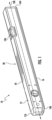
FIG. 1 is a perspective view of a level, according to an exemplary embodiment. -
FIG. 2 is a perspective view of the level ofFIG. 1 with the slidable body member extended. -
FIG. 3 is an exploded perspective view of the level ofFIG. 1 . -
FIG. 4 is an exploded perspective view of the level ofFIG. 1 , viewed from another perspective. -
FIG. 5 is a perspective view of an extension piece including a rear bushing, according to an exemplary embodiment. -
FIG. 6 is a perspective view of the extension piece ofFIG. 5 , viewed from another perspective. -
FIG. 7 is a perspective view of a rear bushing, according to an exemplary embodiment. -
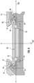
FIG. 8 is a cross-sectional view of a portion of a level comprising an extension, rear bushing and level frame, according to an exemplary embodiment. -
FIG. 9 is a bottom view of the rear bushing ofFIG. 7 . -
FIG. 10 is a perspective view of a front bushing coupled to a level frame, according to an exemplary embodiment. -
FIG. 11 is a cross-section view of a level, comprising a level frame and a front bushing, according to an exemplary embodiment. -
FIG. 12 is a top view of the front bushing ofFIG. 10 . -
FIG. 13 is a perspective view of a braking mechanism, according to an exemplary embodiment. -
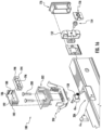
FIG. 14 is an exploded view of the braking mechanism ofFIG. 13 . -
FIG. 15 is an exploded view of the braking mechanism ofFIG. 13 , viewed from another perspective. -
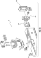
FIG. 16 is an exploded view of a level, including a vial component, an extension restricting component and a front bushing, according to an exemplary embodiment. -
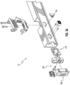
FIG. 17 is an exploded view of the level ofFIG. 16 , viewed from another perspective. -
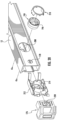
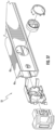
FIG. 18 is a detailed schematic perspective view of a level including an end cap, according to an exemplary embodiment. -
FIG. 19 is a detailed schematic perspective view of a level and an extension, according to an exemplary embodiment. -
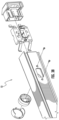
FIG. 20 is an exploded view of a level, including a vial component and an end cap, according to an exemplary embodiment. -
FIG. 21 is an exploded view of the level ofFIG. 20 , viewed from another perspective. -
FIG. 22 is an exploded perspective view of a level according to an exemplary embodiment. -
FIG. 23 is an exploded perspective view of the level ofFIG. 22 , viewed from another perspective. -
FIG. 24 is a perspective view of an extension piece including a rear bushing, according to an exemplary embodiment. -
FIG. 25 is a perspective view of the extension piece ofFIG. 24 , viewed from another perspective. -
FIG. 26 is a perspective view of a rear bushing, according to an exemplary embodiment. -
FIG. 27 is a cross-sectional view of a portion of a level comprising an extension, rear bushing and level frame, according to an exemplary embodiment. -
FIG. 28 is a bottom view of the rear bushing ofFIG. 26 . -
FIG. 29 is a perspective view of a front bushing coupled to a level frame, according to an exemplary embodiment. -
FIG. 30 is a cross-section view of a level, comprising a level frame and a front bushing, according to an exemplary embodiment. -
FIG. 31 is a top view of the front bushing ofFIG. 29 . -
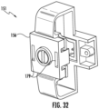
FIG. 32 is a perspective view of a braking mechanism, according to an exemplary embodiment. -
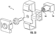
FIG. 33 is an exploded view of the braking mechanism ofFIG. 32 . -
FIG. 34 is an exploded view of the braking mechanism ofFIG. 32 , viewed from another perspective. -
FIG. 35 is an exploded view of a level, including a vial component, an extension restricting component and a front bushing, according to an exemplary embodiment. -
FIG. 36 is an exploded view of the level ofFIG. 35 , viewed from another perspective. -
FIG. 37 is an exploded view of a level, including a vial component and an end cap, according to an exemplary embodiment. -
FIG. 38 is an exploded view of the level ofFIG. 37 , viewed from another perspective. - Referring generally to the figures, various embodiments of a level, such as a spirit level, are shown. In general, levels have one or more precision surfaces used for engagement with a workpiece during leveling. The level discussed herein is designed such that the level's length can be adjusted by the user as needed for various leveling applications. As will be discussed in more detail below, Applicant has developed a variety of innovative mechanisms for an extendable level that provide for smooth and stable relative motion between level sections, adjustable level of friction between level sections, a high visibility vial surround arrangement particularly suited to an extendable level design and/or an end cap design particularly suited to an extendable level design. In general, the levels discussed herein are extendable and are configured to engage a workpiece with at least one extendable and continuous working surface. As used herein an extendable continuous working surface is one that is both length adjustable and that defines a contiguous, coplanar working surface that extends uninterrupted between opposing first and second ends of the level.
- In a specific embodiment, Applicant's level provides a level with a primary body and an extension piece that have coplanar upper and lower working surfaces. A benefit of this configuration is that, independent of length the level has been adjusted to, the level provides one or more continuous coplanar working surface to engage with the desired surface of a workpiece.
- In various embodiments, the extension is moved along level frame via a longitudinal axis to expand or contract the length of the level. The extension comprises an internal cavity that extends along its length and engages around one or more protrusions from the frame. The interface between the extension and the frame is further affected by two bushings. One bushing is coupled to the frame and comprises a spring that is biased against the extension, exerting a force between the frame and the extension. The other bushing is coupled to the extension and comprises a spring that is biased against the frame, also exerting a force between the extension and the frame.
- In various embodiments, the level comprises a braking mechanism that can be adjusted to control an amount of friction that resists axial movement between the extension and the frame. This braking mechanism is adjustable by the user of the level which allows the user to control the amount of resistance to axial movement provided by the braking mechanism. In specific embodiments, the braking mechanism comprises a screw that engages with a threaded brake that exerts an adjustable amount of lateral force against the extension.
- Referring to
FIGS. 1-6 , an extendable, expandable or continuous edge length adjustable level, such aslevel 10, is shown according to an exemplary embodiment. In general,level 10 is extendable in that its length is reversibly adjustable allowing the user to increase and decrease the length oflevel 10 as may be needed for various uses. In general, to expandlevel 10,slidable body member 30 is moved alongframe 12 away fromfixed end 106 alonglongitudinal axis 100, and to retract/collapse level 10,slidable body member 30 is moved alongframe 12 toward fixedend 106. In some embodiments,slidable body member 30 is sized such that its entire length fits betweenfixed end 106 andopen end 104 offrame 12 when in the collapsed position. -
Level 10 includes one or more level indicators, such as level vials 196 (e.g., bubble vials, spirit vials, etc.), which are supported byframe 12 in the appropriate orientation relative tosurfaces 14 and/or 24 in order for the vials to indicate the angle, levelness, degree of plumb, etc. of the corresponding surface of a workpiece, as needed for a particular level design or level type. - Unlike a standard fixed length level with a single integral body that defines the working surfaces, one difficulty with expandable levels is the ability to maintain the coplanar nature of the working surfaces on opposing outer body portions, while at the same time providing a robust and easy to use extendable body design and locking/braking mechanism. As will be discussed in more detail below, the braking mechanism and/or frame designs discussed here are believed to address these potential design issues.
- Referring to
FIG. 1-6 ,level 10 includes arear bushing 70 and afront bushing 110. In general,rear bushing 70 andfront bushing 110 provide robust and low friction sliding contact surfaces. In addition, as discussed in more detail below, bothrear bushing 70 andfront bushing 110 include a spring or biasing structure that exert outwardly directed forces causing a high level of engagement and tight fit betweenbody 12 and theslidable body member 30. -
Rear bushing 70 is coupled toslidable body member 30 via fasteners 52 (e.g., screws) nearenclosed end 36 ofslidable body member 30. During the extension or retraction ofslidable body member 30 alongframe 12,spring 82 ofrear bushing 70 slides alongrear surface 22 offrame 12.Front bushing 110 is coupled to frame 12 via fasteners 52 (e.g., screws) nearopen end 104. During the extension or retraction ofslidable body member 30 alongframe 12, springs 114 offront bushing 110 slide along recessed internalvertical surface 40 ofslidable body member 30. Whenslidable body member 30 is fully extended, stopsurface 96 ofrear bushing 70 engages with hard stop component 60 (best shown inFIG. 17 ) to prevent further extension ofslidable body member 30 and thus defines the maximum extendable length of the level. - Turning to
FIGS. 7-9 ,rear bushing 70 is biased against and pusheslevel frame 12 by virtue ofspring 82. Inparticular spring 82 pushes againstrear surface 22 offrame 12 in direction D1, which results in flexing ofend 86 ofspring 82 deforming in direction D2. The force exerted byspring 82 results inrear bushing 70 being biased in direction D2 away fromframe 12. As a result of that lateral force,rear bushing 70 maintains contact withframe 12 at internalangled surface 25 andslidable body member 30. -
Slidable body member 30 andframe 12 are coupled together via a dovetail fit, which allowsslidable body member 30 andframe 12 to slide with respect to each other alonglongitudinal axis 100. Upperlongitudinal protrusion 27 offrame 12 is engaged withinupper channel 48 ofslidable body member 30, and lowerlongitudinal protrusion 29 offrame 12 is engaged withinlower channel 50 ofslidable body member 30. As a result,slidable body member 30 slides alonglongitudinal axis 100 by virtue of upper and lowerlongitudinal protrusions frame 12 engaging within upper andlower channels slidable body member 30 via a dovetail fit. - In general,
level 10 comprises aframe 12 that comprises abase surface 16 and an opposingtop surface 24.Slidable body member 30 oflevel 10 comprises extensionbottom surface 18 andupper edge 31.Extension bottom surface 18 and framebottom surface 16 are coplanar and collectively comprisebase surface 14.Base surface 14 andtop surface 24 are flat, planar surfaces that can be used to engage a surface of a workpiece to be measured usinglevel 10. In some specific embodiments,base surface 14 and/ortop surface 24 are machined to have a flat, flush or planar surface following formation of frame 12 (e.g., following extrusion of a metal forming frame 12), and in some embodiments, this machined surface may be anodized.Surfaces level 10.Surfaces longitudinal axis 100 oflevel 10. In various embodiments,upper edge 31 ofslidable body member 30 is embedded in the plane oftop surface 24. In various other embodiments,upper edge 31 is slightly elevated above the plane oftop surface 24. - Turning to
FIGS. 10-12 ,front bushing 110 is similarly biased against and pusheslevel frame 12 by virtue ofsprings 114. Inparticular springs 114 push recessed internalvertical surface 40 in direction D2, which results in flexing ends 118 ofsprings 114 deforming in direction D1. The force exerted bysprings 114 results infront bushing 110 being biased in direction D1 away fromslidable body member 30. Therefore,front bushing 110 maintains contact withframe 12 at internalangled surface 25. - Turning to
FIGS. 13-15 ,braking mechanism 150 provides the user the ability to control the ease with whichslidable body member 30 extends and retracts alonglevel frame 12. In general, springs 82 and 114 are positioned to provide a constant but relatively low level of friction to control the sliding ofslidable body member 30 relative to frame 12. When providing a low but non-zero level of friction, springs 82 and 114 increase the amount of force that must be applied in order to slideslidable body member 30 alongframe 12. This constant friction decreases the chance of unintended movement ofslidable body member 30. In specific embodiments, an adjustment control 154 (e.g., via ascrew 154 or other mechanism) allows the user to adjust the amount of friction applied bybraking mechanism 150 toslidable body member 30, which in turn allows the user to adjust how freelyslidable body member 30 slides relative to frame 12. -
Braking mechanism 150 may be adjusted to exert a biasing pressure againstslidable body member 30 in direction D2. The increase in this frictional force betweenbraking mechanism 150 andslidable body member 30 can be increased until the force required to moveslidable body member 30 alonglongitudinal axis 100 is very large (and thusslidable body member 30 is effectively locked in position relative to frame 12). -
Adjustable interface 154 comprisesprotrusions 164 that engage withthread 166 ofbrake 158. In various embodimentsadjustable interface 154 is a custom-threaded bolt that matches the threads ofnut 166. Asadjustable interface 154 is rotated,protrusions 164 correspondingly rotate withinhelical thread 166, which causesbrake 158 to move alonglateral axis 101. In one embodiment, whenadjustable interface 154 is rotated in a clockwise direction, from the perspective ofFIG. 13 , the engagement betweenprotrusions 164 andthread 166 causes brake 158 to move in direction D2 towardsfront bushing 110. As a result,engagement surface 170 ofbrake 158 moves towardsfront bushing 110, and thereby increases the compressive force exerted betweensprings 114 andslidable body member 30. Whenadjustable interface 154 is rotated in a counter-clockwise direction, from the perspective ofFIG. 13 , the engagement betweenprotrusions 164 andthread 166 causes brake 158 to move in direction D1 away fromfront bushing 110. As a result, the compressive force exerted betweensprings 114 andslidable body member 30 is reduced, and less force is required to moveslidable body member 30 alonglongitudinal axis 100. - Turning to
FIGS. 16-17 ,level 10 comprises one or moreorientation measuring components 180, forexample vials 196. As will be explained below,orientation measuring component 180 provides a visual backdrop forvials 196 that allowsvials 196 to be more easily read and interpreted.Bracket 204 is secured withinchamber 206 inlevel frame 12.Mount 202 is placed withinbracket 204 and secured viafasteners 200.Vial frame 194 is placed inmount 202, andvial 196 is mounted withinvial frame 194. In one embodiment, backsurface 186,sidewall surface 188 andbottom surface 192 ofvial frame 194 are a contrasting color to a liquid withinvial 196. For example, inFIG. 16 surfaces vial 196 is blue. In this example, the bubble withinvial 196 is clearly visible compared to the blue liquid against the backdrop ofsurfaces - As noted above, when
slidable body member 30 is fully extended, stopsurface 96 ofrear bushing 70 engages withhard stop component 60 to prevent further extension ofslidable body member 30 and thus defines the maximum extendable length of the level. In various embodimentshard stop component 60 is mounted to one offrame 12 andslidable body member 30. - Turning to
FIG. 18 , whenend cap 176 is removably coupled to fixedend 106 offrame 12,internal member 238 ofend cap 176 is slid withinframe 12.Engagement protrusion 230 presses against an internal surface offrame 12 and deformsengagement pivot 232 aspivot end 234 is partially rotated aroundpivot base 236. When engagement protrusions 230 aligns withopening 178,engagement protrusion 230 engages withopening 178, thereby couplingend cap 176 andframe 12. To remove,engagement protrusion 230nearest pivot end 234 is pressed to de-coupleengagement protrusion 230 from opening 178. - Turning to
FIG. 19 , to facilitate the extension ofslidable body member 30,extension end cap 32 includes a cavity, such asrecess 220 behindback surface 222 ofextension end cap 32. A user may find gripping purchase withrecess 220, thus providing enough frictional engagement between the user andextension end cap 32 to allowslidable body member 30 to be axially moved with respect to frame 12. - Turning to
FIGS. 20-21 ,vial frame 194 is placed withinbracket 212 and then mount 210 is attached.Bracket 212 is secured withinchamber 208 oflevel frame 12. Subsequent tobracket 212 being secured withinchamber 208 offrame 12,end cap 176 is inserted intoframe 12. As before, in various embodiments sidewallsurface 214 are a contrasting color to (e.g., light grey, white, off-white) a liquid withinvial 196, which is blue. In this example, the bubble withinvial 196 is clearly visible compared to the blue liquid againstsidewall surface 214. - In specific embodiments, the level body components (such as
frame 12 and slidable body member 30) discussed herein are each formed from a hollow piece of material, such as hollow pieces of metal material (e.g., hollow pieces of extruded aluminum). Further, it should be understood that the terms vertical and horizontal used herein refer to reference axes where horizontal is a plane that lies parallel to the working surfaces of the level and vertical is a plane that lies perpendicular to the working surfaces of the level. - In specific embodiments, one or more components of
level 10, such asbushings braking mechanism 150, are formed from a low wear, relatively low friction and/or durable polymer material, such a polyoxymethylene polymer material, like Delrin available from DuPont. Further to facilitate fine adjustments of the amount of friction applied bybraking mechanism 150,brake 158 may have low pitch threading such that each rotation ofscrew 154 translates to a small adjustment in the vertical position change ofbrake 158. - The expanding levels discussed herein comprises one or more bushing structures located between
frame 12 andslidable body member 30. In such embodiments, the bushing structures may provide for improved sliding via controlled friction and/or wear resistance as compared to an arrangement in whichframe 12 directly engagesslidable body member 30. - In various embodiments,
front bushing 110 andrear bushing 70 comprise a low friction, low wear polymer material providing bushing functionality betweenframe 12 andslidable body member 30, facilitating sliding ofslidable body member 30 relative to frame 12. - Referring to
FIG. 22-25 , level 11 is shown according to an exemplary embodiment. Level 11 is substantially the same aslevel 10, except as disclosed and illustrated herein.Level 10 comprisesrear bushing 71 andfront bushing 111, which are illustrated inFIGS. 29 and26 , respectively.Rear bushing 71 andfront bushing 111 are substantially the same asrear bushing 70 andfront bushing 110, respectively, except as disclosed and illustrated herein. - Referring to
FIGS. 26-28 ,rear bushing 71 is shown according to an exemplary embodiment.Rear bushing 71 is substantially the same asrear bushing 70, except as disclosed and illustrated herein.Rear bushing 71 comprisesengagement component 88 havingribs 90.Rear bushing 71 is coupled toslidable body member 30. During extension or retraction ofslidable body member 30 alongframe 12,engagement component 88 generally, andribs 90 specifically, engage againstframe 12. In variousembodiments engagement component 88 generally andribs 90 specifically are configured to provide a reduced and/or minimized resistance when sliding againstframe 12. In various embodiments,spring 82 inrear bushing 71 extends further thanupper protrusion 76 and lower protrusion 80 (best shown inFIG. 28 ). - Referring to
FIGS. 29-31 ,front bushing 111 is shown according to an exemplary embodiment.Front bushing 111 is substantially the same asfront bushing 110, except as disclosed and illustrated herein.Front bushing 111 comprisesengagement component 140.Front bushing 111 is coupled toframe 12. During extension or retraction ofslidable body 30 alongframe 12,engagement component 140 engages againstslidable body member 30.Springs 114 infront bushing 111 extend laterally and/or upwards towardsslidable body member 30, whereassprings 114 infront bushing 110 are arcuate shaped (best shown inFIGS. 10 and12 ), and initially extend towardsslidable body member 30 and later extend away fromslidable body member 30. In variousembodiments engagement component 140 generally is configured to provide a reduced and/or minimized resistance when sliding againstslidable body member 30. - Referring to
FIGS. 32-34 ,braking mechanism 151 is shown according to an exemplary embodiment.Braking mechanism 151 is substantially the same asbraking mechanism 150, except as disclosed and illustrated herein.Tightener bracket 156 includesapertures 179 on the surface facing away frombrake 158. In various embodiments ofbraking mechanism 151,thread 166 inbrake 158 is molded withinbrake 158. - Referring to
FIGS. 35-36 , level 11 is shown according to an exemplary embodiment. Level 11 is substantially the same aslevel 10, except as disclosed and illustrated herein. Level 11 comprisesfront bushing 111 andbraking mechanism 151. In the embodiment shown, springs 114 offront bushing 111 extend towardsend cap 176. - Referring to
FIGS. 37-38 ,level 13 is shown according to an exemplary embodiment. Level 11 is substantially the same aslevel 10, except as disclosed and illustrated herein. - It should be understood that the figures illustrate the exemplary embodiments in detail, and it should be understood that the present application is not limited to the details or methodology set forth in the description or illustrated in the figures. It should also be understood that the terminology is for the purpose of description only and should not be regarded as limiting.
- Further modifications and alternative embodiments of various aspects of the invention will be apparent to those skilled in the art in view of this description. Accordingly, this description is to be construed as illustrative only. The construction and arrangements, shown in the various exemplary embodiments, are illustrative only. Although only a few embodiments have been described in detail in this disclosure, many modifications are possible (e.g., variations in sizes, dimensions, structures, shapes and proportions of the various elements, values of parameters, mounting arrangements, use of materials, colors, orientations, etc.) without materially departing from the novel teachings and advantages of the subject matter described herein. Some elements shown as integrally formed may be constructed of multiple parts or elements, the position of elements may be reversed or otherwise varied, and the nature or number of discrete elements or positions may be altered or varied. The order or sequence of any process, logical algorithm, or method steps may be varied or re-sequenced according to alternative embodiments. Other substitutions, modifications, changes and omissions may also be made in the design, operating conditions and arrangement of the various exemplary embodiments without departing from the scope of the present invention.
- Unless otherwise expressly stated, it is in no way intended that any method set forth herein be construed as requiring that its steps be performed in a specific order. Accordingly, where a method claim does not actually recite an order to be followed by its steps or it is not otherwise specifically stated in the claims or descriptions that the steps are to be limited to a specific order, it is in no way intended that any particular order be inferred. In addition, as used herein the article "a" is intended to include one or more components or elements, and is not intended to be construed as meaning only one.
- Various embodiments of the invention relate to any combination of any of the features, and any such combination of features may be claimed in this or future applications. Any of the features, elements, or components of any of the exemplary embodiments discussed above may be utilized alone or in combination with any of the features, elements, or components of any of the other embodiments discussed above.
- In various exemplary embodiments, the relative dimensions, including angles, lengths and radii, as shown in the Figures are to scale. Actual measurements of the Figures will disclose relative dimensions, angles and proportions of the various exemplary embodiments. Various exemplary embodiments extend to various ranges around the absolute and relative dimensions, angles and proportions that may be determined from the Figures. Various exemplary embodiments include any combination of one or more relative dimensions or angles that may be determined from the Figures. Further, actual dimensions not expressly set out in this description can be determined by using the ratios of dimensions measured in the Figures. in combination with the express dimensions set out in this description. In addition, in various embodiments, the present disclosure extends to a variety of ranges (e.g., plus or minus 30%, 20%, or 10%) around any of the absolute or relative dimensions disclosed herein or determinable from the Figures.
The following clauses may define aspects or embodiments of the present invention: -
Clause 1. A level comprising:- a frame comprising:
- a first planar base surface;
- a top surface opposing the base surface;
- a longitudinal axis;
- a fixed end at a first end of the longitudinal axis;
- an open end opposing the fixed end; and
- an orientation measuring component;
- a slidable body member coupled to the frame that extends and retracts along the longitudinal axis of the frame, the slidable body member comprising:
- a second planar base surface generally coplanar with the first planar base surface;
- an enclosed end; and
- an adjustable end opposing the enclosed end, the adjustable end extending past the open end of the frame when the slidable body member is fully extended;
- a first bushing that couples the slidable body member and the frame, the first bushing fixedly coupled to one of the frame or the slidable body member; and
- a second bushing that couples the slidable body member and the frame, the second bushing fixedly coupled to one of the frame or the slidable body member.
- a frame comprising:
-
Clause 2. The level ofClause 1, the first bushing being fixedly coupled to the frame closer to the open end than the fixed end, the first bushing is biased against and pushes the slidable body member via a first force, and the second bushing being fixedly coupled to the slidable body member closer to the enclosed end than the adjustable end, the second bushing is biased against and pushes the frame via a second force. - Clause 3. The level of
Clause 2, the first planar base surface of the frame and the second planar base surface of the slidable body member collectively comprising a generally continuous base surface to engage against a workpiece. -
Clause 4. The level ofClause 2, the level further comprising a braking mechanism to increase a resistive force against sliding the slidable body member along the longitudinal axis of the frame. - Clause 5. The level of
Clause 2, the slidable body member comprising a first protrusion that extends into a first channel of the frame, the first force exerted by the first bushing and the second force exerted by the second bushing maintaining an engagement between a surface of the first protrusion and a surface of the first channel. - Clause 6. The level of
Clause 2, the slidable body member comprising a first protrusion that extends into a first channel of the frame and a second protrusion that extends into a second channel of the frame, the first force exerted by the first bushing and the second force exerted by the second bushing both being a separating force between the frame and the slidable body member, the first and second protrusions of the slidable body member both being engaged against each of the first and second bushings by the first and second forces. - Clause 7. The level of Clause 6, the level further comprising a braking mechanism to increase a resistive force against sliding the slidable body member along the longitudinal axis of the frame.
- Clause 8. The level of Clause 7, the braking mechanism comprising an adjustable interface and a brake to variably adjust the resistive force against sliding the slidable body member along the longitudinal axis of the frame.
- Clause 9. The level of Clause 6, the first bushing comprising two spring protrusions that are engaged against the slidable body member, the first bushing further comprising a top cavity and a bottom cavity that respectively engage around an upper protrusion and a lower protrusion of the frame.
-
Clause 10. The level of Clause 9, the second bushing comprising a spring protrusion that is engaged against the frame, the second bushing further comprising an upper cavity and a lower cavity that respectively engage around the upper protrusion and the lower protrusion of the frame. - Clause 11. The level of
Clause 10, wherein the second bushing comprises a stop surface that engages against a stop component fixedly coupled to the frame when the slidable body member is fully extended from the frame. -
Clause 12. The level ofClause 10, the first bushing comprising an engagement component at a flexing end of each of the springs, the engagement components each comprising ribs that are generally aligned with the frame's longitudinal axis and engaging against the slidable body member. -
Clause 13. The level ofClause 10, the second bushing comprising an engagement component at a flexing end of the spring, the engagement component comprising ribs that are generally aligned with the frame's longitudinal axis and engaging against the frame. -
Clause 14. A level comprising:- a frame comprising:
- a first planar base surface;
- a top surface opposing the base surface;
- a longitudinal axis;
- a fixed end at a first end of the longitudinal axis;
- an open end opposite the fixed end; and
- at least two orientation measuring components;
- a slidable body member coupled to the frame that extends and retracts along the longitudinal axis of the frame, the slidable body member comprising:
- a second planar base surface generally coplanar with the first planar base surface;
- an adjustable end that extends past the open end of the frame when the slidable body member is fully extended;
- a first bushing that couples the slidable body member and the frame, the first bushing fixedly coupled to the frame; and
- a second bushing that couples the slidable body member and the frame, the second bushing fixedly coupled to the slidable body member.
- a frame comprising:
- Clause 15. The level of
Clause 14, the slidable body member comprising a first protrusion that extends into a first channel of the frame, the first bushing exerting a first separating force between the frame and the slidable body member, and the second bushing exerting a second separating force between the frame and the slidable body member. -
Clause 16. The level of Clause 15, the first protrusion of the slidable body member being engaged against the first and second bushings by the first and second forces. - Clause 17. The level of
Clause 16, the first bushing comprising an engagement component at a flexing end of each of the springs, the first bushing's engagement components engaging against the slidable body member and comprising ribs that are generally aligned with the frame's longitudinal axis, and the second bushing comprising an engagement component at a flexing end of the spring, the second bushing's engagement component engaging against the frame and comprising ribs that are generally aligned with the frame's longitudinal axis. -
Clause 18. A level comprising:- a frame comprising:
- a first planar base surface;
- a top surface opposing the base surface;
- a longitudinal axis;
- an open end at a first end of the longitudinal axis; and
- an orientation measuring component;
- a slidable body member coupled to the frame that extends and retracts along the longitudinal axis of the frame, the slidable body member comprising:
- a second planar base surface generally coplanar with the first planar base surface;
- an adjustable end that extends past the open end of the frame when the slidable body member is fully extended;
- a first bushing that couples the slidable body member and the frame, the first bushing fixedly coupled to one of the frame or the slidable body member; and
- a second bushing that couples the slidable body member and the frame, the second bushing fixedly coupled to one of the frame or the slidable body member.
- a frame comprising:
- Clause 19. The level of
Clause 18, the first bushing being fixedly coupled to the frame and exerting a first force on the slidable body member, and the second bushing being fixedly coupled to the slidable body member and exerting a second force on the frame. -
Clause 20. The level of Clause 19, the first bushing comprising an engagement component at a flexing end of each of the springs, the engagement components engaging against the slidable body member and comprising ribs that are generally aligned with the frame's longitudinal axis, and the second bushing comprising an engagement component at a flexing end of the spring, the engagement component engaging against the frame and comprising ribs that are generally aligned with the frame's longitudinal axis.
Claims (15)
- A level comprising:a frame comprising:a first planar base surface;a top surface opposing the base surface;a longitudinal axis;a fixed end at a first end of the longitudinal axis;an open end opposite the fixed end; andat least two orientation measuring components;a slidable body member coupled to the frame that extends and retracts along the longitudinal axis of the frame, the slidable body member comprising:a second planar base surface generally coplanar with the first planar base surface; andan adjustable end that extends past the open end of the frame when the slidable body member is fully extended;a first bushing that couples the slidable body member and the frame, the first bushing fixedly coupled to the frame; anda second bushing that couples the slidable body member and the frame, the second bushing fixedly coupled to the slidable body member.
- The level of claim 1, the slidable body member comprising a first protrusion that extends into a first channel of the frame, the first bushing exerting a first separating force between the frame and the slidable body member, and the second bushing exerting a second separating force between the frame and the slidable body member.
- The level of claim 2, the first protrusion of the slidable body member being engaged against the first and second bushings by the first and second forces, and optionally or preferably, the first bushing comprising an engagement component at a flexing end of each of two springs of the first bushing, for each spring of the first bushing the engagement portion engaging against the slidable body member and comprising ribs that are generally aligned with the longitudinal axis of the frame, and the second bushing comprising an engagement component at a flexing end of a spring, the engagement component of the second bushing engaging against the frame and comprising ribs that are generally aligned with the longitudinal axis of the frame.
- A level comprising:a frame comprising:a first planar base surface;a top surface opposing the base surface;a longitudinal axis;an open end at a first end of the longitudinal axis; andan orientation measuring component;a slidable body member coupled to the frame that extends and retracts along the longitudinal axis of the frame, the slidable body member comprising:a second planar base surface generally coplanar with the first planar base surface; andan adjustable end that extends past the open end of the frame when the slidable body member is fully extended;a first bushing that couples the slidable body member and the frame, the first bushing fixedly coupled to one of the frame or the slidable body member; anda second bushing that couples the slidable body member and the frame, the second bushing fixedly coupled to one of the frame or the slidable body member.
- The level of claim 4, the first bushing being fixedly coupled to the frame and exerting a first force on the slidable body member, and the second bushing being fixedly coupled to the slidable body member and exerting a second force on the frame, and optionally or preferably, the first bushing comprising an engagement component at a flexing end of each of two springs of the first bushing, for each spring of the first bushing the engagement portion engaging against the slidable body member and comprising ribs that are generally aligned with the longitudinal axis of the frame, and the second bushing comprising an engagement component at a flexing end of the spring, the engagement component engaging against the frame and comprising ribs that are generally aligned with the longitudinal axis of the frame.
- The level of claims 1 or 4, the first planar base surface of the frame and the second planar base surface of the slidable body member collectively comprising a generally continuous base surface to engage against a workpiece.
- The level of claim 3, the slidable body member comprising a second protrusion that extends into a second channel of the frame.
- The level of claims 1 or 4, further comprising a braking mechanism to increase a resistive force against sliding the slidable body member along the longitudinal axis of the frame.
- The level of claim 8, the braking mechanism comprising an adjustable interface and a brake to variably adjust the resistive force against sliding the slidable body member along the longitudinal axis of the frame.
- The level of claims 1 or 4, the first bushing being fixedly coupled to the frame.
- The level of claim 10, the second bushing being fixedly coupled to the slidable body member.
- The level of claim 11, the second bushing comprising a stop surface that interfaces with the frame when the slidable body member is fully extended, thereby defining a maximum extendable length of the level.
- The level of claims 1 or 4, the frame comprising a fixed end opposite the open end, wherein the slidable body member is sized such that an entire length of the slidable body member fits between the open end and the fixed end of the frame.
- The level of claims 1 or 4, the frame comprising a fixed end opposite the open end, the level further comprising an end cap assembly detachably coupled to the fixed end of the frame, the end cap assembly comprising an engagement pivot configured to engage an opening in the frame, the engagement pivot comprising a pivot base and a pivot end, the pivot end rotates with respect to the pivot base when the engagement pivot is detached from the frame, wherein the pivot end is located between the pivot base and the fixed end of the frame when the end cap assembly is engaged with the opening in the frame.
- The level of claim 14, wherein the pivot end rotates with respect to the pivot base about a second axis perpendicular to the longitudinal axis of the frame.
Applications Claiming Priority (3)
| Application Number | Priority Date | Filing Date | Title |
|---|---|---|---|
| CN201810750787.1A CN110702075B (en) | 2018-07-10 | 2018-07-10 | Adjustable level with continuous edge |
| PCT/US2019/041031 WO2020014247A1 (en) | 2018-07-10 | 2019-07-09 | Continuous edge adjustable level |
| EP19834628.0A EP3821203B1 (en) | 2018-07-10 | 2019-07-09 | Continuous edge adjustable level |
Related Parent Applications (1)
| Application Number | Title | Priority Date | Filing Date |
|---|---|---|---|
| EP19834628.0A Division EP3821203B1 (en) | 2018-07-10 | 2019-07-09 | Continuous edge adjustable level |
Publications (2)
| Publication Number | Publication Date |
|---|---|
| EP4579179A2 true EP4579179A2 (en) | 2025-07-02 |
| EP4579179A3 EP4579179A3 (en) | 2025-12-24 |
Family
ID=69141643
Family Applications (2)
| Application Number | Title | Priority Date | Filing Date |
|---|---|---|---|
| EP19834628.0A Active EP3821203B1 (en) | 2018-07-10 | 2019-07-09 | Continuous edge adjustable level |
| EP25165717.7A Pending EP4579179A3 (en) | 2018-07-10 | 2019-07-09 | Continuous edge adjustable level |
Family Applications Before (1)
| Application Number | Title | Priority Date | Filing Date |
|---|---|---|---|
| EP19834628.0A Active EP3821203B1 (en) | 2018-07-10 | 2019-07-09 | Continuous edge adjustable level |
Country Status (4)
| Country | Link |
|---|---|
| US (3) | US11085763B2 (en) |
| EP (2) | EP3821203B1 (en) |
| CN (2) | CN117288164A (en) |
| WO (1) | WO2020014247A1 (en) |
Families Citing this family (6)
| Publication number | Priority date | Publication date | Assignee | Title |
|---|---|---|---|---|
| CN111989543B (en) | 2018-02-27 | 2023-02-10 | 米沃奇电动工具公司 | Adjustable length level |
| USD867910S1 (en) * | 2018-04-27 | 2019-11-26 | Milwaukee Electric Tool Corporation | Digital level |
| CN117288164A (en) * | 2018-07-10 | 2023-12-26 | 米沃奇电动工具公司 | Level meter |
| USD943433S1 (en) * | 2020-02-10 | 2022-02-15 | Mark Parrish | Dual measuring level |
| US11193763B1 (en) * | 2021-03-15 | 2021-12-07 | Michael H. Panosian | Extendible level with non-coplanar extension surface |
| US11686578B2 (en) * | 2021-06-09 | 2023-06-27 | Uwe Schiel | Expandable level |
Family Cites Families (31)
| Publication number | Priority date | Publication date | Assignee | Title |
|---|---|---|---|---|
| SE305086B (en) * | 1967-12-14 | 1968-10-14 | H Thingstad | |
| US4130943A (en) * | 1977-07-22 | 1978-12-26 | Talbot Claude J | Extension level |
| SE440539B (en) | 1983-12-15 | 1985-08-05 | Armerad Betong Ab | MACHINE ITEMS IN THE FORM OF TELESCOPIC WITH ANOTHER RELAYABLE, PREFERRED RECTANGULAR PROFILES |
| US4733475A (en) * | 1987-05-20 | 1988-03-29 | Youmans John W | Extension level apparatus |
| US4928395A (en) * | 1989-06-06 | 1990-05-29 | Good Laverne C | Extensible level |
| US5433011A (en) * | 1993-04-27 | 1995-07-18 | Scarborough; Dane | Combination interlocking segmented level |
| US6058617A (en) * | 1997-12-31 | 2000-05-09 | Nadu; Samuel | Audio visual combination extension level |
| US6041510A (en) * | 1998-03-18 | 2000-03-28 | Huff; Charles A. | Extension level, square and length gauge |
| US6658752B1 (en) * | 1998-06-12 | 2003-12-09 | Anthony L. Bonaventura, Jr. | Extensible carpenter's level |
| US6279240B1 (en) * | 1998-06-12 | 2001-08-28 | Anthony Louis Bonaventura, Jr. | Extensible carpenter's level |
| US6293023B1 (en) * | 1999-04-29 | 2001-09-25 | Jason R. Crowe | Level |
| US6637120B2 (en) * | 2001-01-18 | 2003-10-28 | Joseph Pustay | Extendable level |
| GB0311445D0 (en) * | 2003-05-19 | 2003-06-25 | Lhm Design Ltd | Spirit level |
| CN2647985Y (en) * | 2003-07-28 | 2004-10-13 | 王力集团有限公司 | Auto-telescopic mechanism for bolt of door lock |
| US7497022B1 (en) * | 2006-04-04 | 2009-03-03 | James Arthur Aarhus | Plate level |
| US7596877B2 (en) * | 2006-11-17 | 2009-10-06 | Basford Clifford W | Mason's adjustable alignment tool |
| US8413343B2 (en) * | 2007-11-05 | 2013-04-09 | Brian K. HALE | Extendable plumb and level measuring device and associated usage method |
| US8286363B1 (en) * | 2010-05-03 | 2012-10-16 | Richard J Martinez | Screw mount placement device |
| US8852258B2 (en) * | 2011-10-24 | 2014-10-07 | Novostent Corporation | Catheter assembly with user-assisting handle |
| US20130326895A1 (en) * | 2012-06-08 | 2013-12-12 | George Bureau | Extendable Level |
| US20150128432A1 (en) * | 2013-11-08 | 2015-05-14 | Jonathon Jacob Penneman | Slidable Alignment Apparatus |
| US9709393B2 (en) * | 2014-07-16 | 2017-07-18 | Michael Oppenheim | Device for making collinear equidistant marks |
| DE102016103334A1 (en) | 2016-02-09 | 2017-08-10 | STABILA Messgeräte Gustav Ullrich GmbH | spirit level |
| US20170370715A1 (en) * | 2016-06-28 | 2017-12-28 | Donald E. KENNIS | Expandable level |
| US10458790B2 (en) * | 2016-12-01 | 2019-10-29 | C&B Products Llc | Space determining device and system and method for capturing dimensions and mounting objects |
| CN111989543B (en) * | 2018-02-27 | 2023-02-10 | 米沃奇电动工具公司 | Adjustable length level |
| USD866365S1 (en) * | 2018-04-28 | 2019-11-12 | Milwaukee Electric Tool Corporation | Level |
| CN117288164A (en) * | 2018-07-10 | 2023-12-26 | 米沃奇电动工具公司 | Level meter |
| DE102020109498B4 (en) * | 2020-04-06 | 2023-03-09 | STABILA Messgeräte Gustav Ullrich GmbH | level |
| US11578975B2 (en) * | 2020-11-26 | 2023-02-14 | STABILA Messgeräte Gustav Ullrich GmbH | Spirit level |
| US11255667B1 (en) * | 2021-04-22 | 2022-02-22 | Michael H. Panosian | Extendible level with non-coplanar extension surface |
-
2018
- 2018-07-10 CN CN202311156351.7A patent/CN117288164A/en active Pending
- 2018-07-10 CN CN201810750787.1A patent/CN110702075B/en active Active
-
2019
- 2019-07-09 WO PCT/US2019/041031 patent/WO2020014247A1/en not_active Ceased
- 2019-07-09 EP EP19834628.0A patent/EP3821203B1/en active Active
- 2019-07-09 EP EP25165717.7A patent/EP4579179A3/en active Pending
- 2019-07-23 US US16/519,718 patent/US11085763B2/en active Active
-
2021
- 2021-07-21 US US17/381,453 patent/US11650053B2/en active Active
-
2023
- 2023-04-17 US US18/301,758 patent/US12306016B2/en active Active
Also Published As
| Publication number | Publication date |
|---|---|
| EP4579179A3 (en) | 2025-12-24 |
| EP3821203A1 (en) | 2021-05-19 |
| US12306016B2 (en) | 2025-05-20 |
| EP3821203B1 (en) | 2025-04-23 |
| US20210356270A1 (en) | 2021-11-18 |
| US20200018597A1 (en) | 2020-01-16 |
| CN110702075B (en) | 2023-09-29 |
| WO2020014247A1 (en) | 2020-01-16 |
| US11650053B2 (en) | 2023-05-16 |
| US11085763B2 (en) | 2021-08-10 |
| US20230251085A1 (en) | 2023-08-10 |
| EP3821203A4 (en) | 2022-07-20 |
| CN110702075A (en) | 2020-01-17 |
| CN117288164A (en) | 2023-12-26 |
Similar Documents
| Publication | Publication Date | Title |
|---|---|---|
| US12306016B2 (en) | Continuous edge adjustable level | |
| US12304143B2 (en) | Length adjustable level | |
| US11131421B2 (en) | Adjustable extension arm device | |
| US11686580B2 (en) | Level with rotating vial and locking assembly | |
| EP1460001A1 (en) | Pump with function of measuring fixed amount | |
| US20150158364A1 (en) | Adjustable damping curve shock absorber | |
| JPH01227903A (en) | Dial cylinder gage | |
| US6868618B2 (en) | Gauge and method | |
| CN210124801U (en) | Fine-adjustment retractor for neurosurgery operation | |
| CN110401092A (en) | A kind of laser angle regulating device | |
| CN223558603U (en) | An adjustable slitting blade and an adjustable slitting device | |
| CN219829831U (en) | Height gauge convenient to adjust | |
| CN214578054U (en) | Cylinder structure capable of adapting to fixed position | |
| CN222627524U (en) | A fixture for repairing mechanical products | |
| CN213560633U (en) | Supporting structure and pipe cutting machine | |
| US9073203B2 (en) | Marking tool | |
| CN119982715A (en) | A hydraulic cylinder with double-end adjustable stroke | |
| IES20050248A2 (en) | An apparatus for drawing in and dispensing a measured quantity of a liquid | |
| CN109341501A (en) | A kind of automotive seat track cubing | |
| ITMI20110380U1 (en) | SYSTEM FOR THE HANDLING OF COMPONENTS, IN PARTICULAR IN FRAMES FOR TELESCOPES | |
| TWM502521U (en) | Cutting device capable of fine tuning notch blade |
Legal Events
| Date | Code | Title | Description |
|---|---|---|---|
| PUAI | Public reference made under article 153(3) epc to a published international application that has entered the european phase |
Free format text: ORIGINAL CODE: 0009012 |
|
| STAA | Information on the status of an ep patent application or granted ep patent |
Free format text: STATUS: THE APPLICATION HAS BEEN PUBLISHED |
|
| AC | Divisional application: reference to earlier application |
Ref document number: 3821203 Country of ref document: EP Kind code of ref document: P |
|
| AK | Designated contracting states |
Kind code of ref document: A2 Designated state(s): AL AT BE BG CH CY CZ DE DK EE ES FI FR GB GR HR HU IE IS IT LI LT LU LV MC MK MT NL NO PL PT RO RS SE SI SK SM TR |
|
| PUAL | Search report despatched |
Free format text: ORIGINAL CODE: 0009013 |
|
| AK | Designated contracting states |
Kind code of ref document: A3 Designated state(s): AL AT BE BG CH CY CZ DE DK EE ES FI FR GB GR HR HU IE IS IT LI LT LU LV MC MK MT NL NO PL PT RO RS SE SI SK SM TR |
|
| RIC1 | Information provided on ipc code assigned before grant |
Ipc: G01C 9/28 20060101AFI20251117BHEP |