Technical Field
-
The present invention relates to a refrigeration device that can switch between a single operation in which the refrigeration device is operated by one refrigerant circuit and a dual operation in which the refrigeration device is operated by two refrigerant circuits are used using a cascade heat exchanger.
Background Art
-
A cascade refrigeration system in the related art includes a high-temperature side refrigerant circuit, a low-temperature side refrigerant circuit, and a cascade heat exchanger (an intermediate heat exchanger) shared by the high-temperature side refrigerant circuit and the low-temperature side refrigerant circuit. The cascade heat exchanger works as an evaporator for a high-temperature side refrigerant circulating through the high-temperature side refrigerant circuit and works as a condenser for a low-temperature side refrigerant circulating through the low-temperature side refrigerant circuit. That is, the cascade heat exchanger performs heat-exchange between the high-temperature side refrigerant and the low-temperature side refrigerant so that a cooling bath (a box in which a cooled target is placed) is cooled by the low-order side refrigerant circulating through the low-temperature side refrigerant circuit. Thus, in the cascade refrigeration system, the cascade heat exchanger performs heat-exchange between the refrigerant circulating through the high-temperature side refrigerant circuit and the refrigerant circulating through the low-temperature side refrigerant circuit, thereby making it possible to increase cooling performance by cooling the cooling bath to a lower temperature than a refrigeration device that performs a normal single operation.
-
Thus, the cascade refrigeration system can increase the cooling performance. In the meantime, two refrigerant circuits, i.e., the high-temperature side refrigerant circuit and the low-temperature side refrigerant circuit, are operated, so that the cascade refrigeration system consumes more energy. On this account, in a case where the cooling performance is not so necessary, the single operation may be suitable.
-
In view of this, PTL 1 discloses a cooling device that switches between a single operation and a dual operation depending on necessary performance or temperature changes so as to improve operating efficiency.
-
A refrigeration device described in PTL 1 includes: a low-temperature side refrigerant circuit including a low-temperature side condenser and a low-temperature side evaporator such that a low-temperature side refrigerant circulating through the low-temperature side refrigerant circuit absorbs heat in the low-temperature side evaporator; and a high-temperature side refrigerant circuit including a high-temperature side condenser, a high-temperature side first evaporator, and a high-temperature side second evaporator such that a high-temperature side refrigerant circulating through the high-temperature side refrigerant circuit absorbs heat in the high-temperature side first evaporator or the high-temperature side second evaporator. A cascade heat exchanger working as the low-temperature side condenser and the high-temperature side second evaporator is formed. The refrigeration device can perform a single operation in which the high-temperature side refrigerant is circulated through the high-temperature side first evaporator so as to cool a cooled object in the high-temperature side first evaporator. The refrigeration device can also perform a dual operation in which the high-temperature side refrigerant is circulated through the high-temperature side second evaporator and the low-order side refrigerant is circulated through the low-temperature side refrigerant circuit so that the high-temperature side refrigerant and the low-temperature side refrigerant exchange heat with each other in the cascade heat exchanger, and the cooled object is cooled in the low-temperature side evaporator. The refrigeration device can switch its operation between the single operation and the dual operation.
Citation List
Patent Literature
-
Summary of Invention
Technical Problem
-
However, in the cascade refrigeration system described in PTL 1, in the case of the single operation, a cooling bath side as a use side device absorbs heat from the low-temperature side refrigerant circuit side via the low-temperature side evaporator of the low-temperature side refrigerant circuit that stops operating. In addition, in the case of the dual operation, the cooling bath side as the use side device absorbs heat from the high-temperature side refrigerant circuit side via the high-temperature side first evaporator through which no refrigerant flows so that the high-temperature side first evaporator does not function as an evaporator (a heat exchanger). Accordingly, the cascade refrigeration system described in PTL 1 has a problem that the amount of heat to be exchanged between the refrigerant in the use side device and the cooled object is insufficient.
-
In view of the above problem, an object of the present invention is to provide a refrigeration device which can switch between a single operation and a dual operation and which can restrain heat-leakage from a use side device to a refrigerant circuit side via a heat exchanger that does not function as a heat exchanger with no refrigerant flowing therethrough.
Solution to Problem
-
One aspect of the present invention is a refrigeration device including: a high-order side refrigerant circuit configured such that a high-order side compressor, a high-order side heat medium heat exchanger configured to perform heat-exchange with a heat medium, a high-order side pressure reduction mechanism, and a cascade heat exchanger are sequentially connected via refrigerant pipes to circulate a high-order side refrigerant through the high-order side refrigerant circuit; a low-order side refrigerant circuit configured such that a low-order side compressor, the cascade heat exchanger, a low-order side heat medium heat exchanger, a low-order side pressure reduction mechanism, and a low-order side heat exchanger are sequentially connected via refrigerant pipes to circulate a low-order side refrigerant through the low-order side refrigerant circuit, the low-order side heat medium heat exchanger being connected in parallel with the cascade heat exchanger and configured to perform heat-exchange with the heat medium; and a control unit configured to control the high-order side refrigerant circuit and the low-order side refrigerant circuit. The control unit switches between a single operation and a dual operation, the single operation being an operation in which the heat medium is heated by the low-order side heat medium heat exchanger by circulating the low-order side refrigerant through the low-order side refrigerant circuit without circulating the high-order side refrigerant through the high-order side refrigerant circuit, the dual operation being an operation in which the heat medium is heated by the high-order side heat medium heat exchanger by circulating the high-order side refrigerant through the high-order side refrigerant circuit, circulating the low-order side refrigerant through the low-order side refrigerant circuit, and performing heat-exchange between the high-order side refrigerant and the low-order side refrigerant in the cascade heat exchanger. The low-order side refrigerant circuit includes a low-order side cutoff unit configured to block the low-order side refrigerant from flowing into the low-order side heat medium heat exchanger, and the high-order side refrigerant circuit includes a high-order side cutoff unit configured to block the high-order side refrigerant from flowing into the high-order side heat medium heat exchanger.
Advantageous Effects of Invention
-
The present invention can provide a refrigeration device which can switch between a single operation and a dual operation and which can restrain heat-leakage from a use side device to a refrigerant circuit side via a heat exchanger that does not function as a heat exchanger with no refrigerant flowing therethrough.
Brief Description of Drawings
-
- FIG. 1 is a refrigerant circuit diagram of a cascade refrigeration system according to a first embodiment of the present invention;
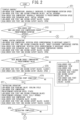
- FIG. 2 is a control flow diagram of the cascade refrigeration system according to the first embodiment of the present invention;
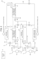
- FIG. 3 is a refrigerant circuit diagram of a cascade refrigeration system according to a second embodiment of the present invention;
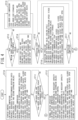
- FIG. 4 is a control flow diagram of the cascade refrigeration system according to the second embodiment of the present invention; and
- FIG. 5 is a refrigerant circuit diagram of a cascade refrigeration system according to a third embodiment of the present invention.
Description of Embodiments
-
Embodiments of a cascade refrigeration system according to the present invention will be hereinafter described in detail with reference to the drawings. Note the present invention is not limited by the embodiments.
-
FIG. 1 is a refrigerant circuit diagram of a cascade refrigeration system 1 according to the present embodiment. FIG. 2 is a control block diagram of the cascade refrigeration system 1 according to the present embodiment.
Examples
-
With reference to FIG. 1, the cascade refrigeration system 1 according to the present embodiment will be described. The cascade refrigeration system 1 is a refrigeration device which can be used for a cooling operation in a case where a high-order side heat medium heat exchanger 11 is used as an evaporator and which can be used for a heating operation in a case where the high-order side heat medium heat exchanger 11 is used as a condenser. The present embodiment deals with a cascade refrigeration system used for the heating operation. The cascade refrigeration system 1 includes a high-order side refrigerant circuit 2, a low-order side refrigerant circuit 3, a heat medium circuit 4, and a control unit 5, and the control unit 5 controls the cascade refrigeration system 1.
-
The high-order side refrigerant circuit 2 is configured such that a high-order side compressor 10, the high-order side heat medium heat exchanger 11 configured to perform heat-exchange with a heat medium such as air or water, a high-order side expansion valve 12 as a high-order side pressure reduction mechanism, and a cascade heat exchanger 13 are sequentially connected via refrigerant pipes 6 to circulate a high-order side refrigerant through the high-order side refrigerant circuit 2. In the present embodiment, the high-order side heat medium heat exchanger 11 is a heat exchanger configured to perform heat-exchange between the high-order side refrigerant and a heat medium flowing through the heat medium circuit 4. The cascade heat exchanger 13 is a heat exchanger configured to perform heat-exchange between the high-order side refrigerant and a low-order side refrigerant flowing through the low-order side refrigerant circuit 3. Note that, in the present embodiment, the high-order side heat medium heat exchanger 11 is a heat exchanger configured to perform heat-exchange between the high-order side refrigerant and the heat medium flowing through the heat medium circuit 4 but may be a heat exchanger configured to perform heat-exchange with air as the heat medium to be sent by an air-sending blower (not illustrated), for example. Arrows in the high-order side refrigerant circuit 2 indicate flows of the high-order side refrigerant in the heating operation.
-
In the high-order side refrigerant circuit 2, a high-order side four-way valve 14 is connected to a discharge side of the high-order side compressor 10, and the high-order side four-way valve 14 is configured to switch between a state where the high-order side refrigerant discharged from the high-order side compressor 10 flows toward the high-order side heat medium heat exchanger 11 side and a state where the high-order side refrigerant flows toward the cascade heat exchanger 13 side. The present embodiment deals with a case (the heating operation) where the high-order side four-way valve 14 causes the high-order side refrigerant discharged from the high-order side compressor 10 to flow toward the high-order side heat medium heat exchanger 11 side. Accordingly, in the high-order side refrigerant circuit 2, the high-order side refrigerant discharged from the high-order side compressor 10 flows through the high-order side heat medium heat exchanger 11, the high-order side expansion valve 12, and the cascade heat exchanger 13 and is then sucked into the high-order side compressor 10.
-
In the high-order side refrigerant circuit 2, a high-order side first cutoff valve 42 is provided on the upstream side (the upstream side in a refrigerant flow in the heating operation) from the high-order side heat medium heat exchanger 11, and a high-order side second cutoff valve 43 is provided on the downstream side (the downstream side in the refrigerant flow in the heating operation) from the high-order side heat medium heat exchanger 11. The high-order side first cutoff valve 42 and the high-order side second cutoff valve 43 are high-order side cutoff units in the present invention. The high-order side first cutoff valve 42 blocks the high-order side refrigerant from flowing into the high-order side heat medium heat exchanger 11 from the upstream side. The high-order side second cutoff valve 43 blocks the high-order side refrigerant from flowing into the high-order side heat medium heat exchanger 11 from the downstream side.
-
The low-order side refrigerant circuit 3 includes a first circulation path 23 and a second circulation path 26. The first circulation path 23 is configured such that a low-order side compressor 20, the cascade heat exchanger 13 connected to the high-order side refrigerant circuit 2, a low-order side first expansion valve 21 as a low-order side pressure reduction mechanism, and a low-order side heat exchanger 22 configured to absorb heat from external air are sequentially connected via refrigerant pipes 6 to circulate a low-order side refrigerant through the first circulation path 23. The cascade heat exchanger 13 is a heat exchanger configured to perform heat-exchange between the low-order side refrigerant and the high-order side refrigerant flowing through the high-order side refrigerant circuit 2. Continuous-line arrows in the low-order side refrigerant circuit 3 indicate flows of the low-order side refrigerant.
-
In the low-order side refrigerant circuit 3, a refrigerant pipe connecting a low-order side four-way valve 27 (described later) to the cascade heat exchanger 13 is connected to a refrigerant pipe connecting the low-order side first expansion valve 21 to the low-order side heat exchanger 22, via refrigerant pipes including a low-order side heat medium heat exchanger 24 and a low-order side second expansion valve 25. The low-order side heat medium heat exchanger 24 performs heat-exchange with the heat medium. Here, the low-order side second expansion valve 25 is a low-order side second pressure reduction mechanism. That is, the cascade heat exchanger 13 and the low-order side heat medium heat exchanger 24 are connected in parallel between the low-order side four-way valve 27 placed on the upstream side and the low-order side heat exchanger 22 placed on the downstream side in the heating operation. The second circulation path 26 is configured such that the low-order side compressor 20, the low-order side heat medium heat exchanger 24, the low-order side second expansion valve 25, and the low-order side heat exchanger 22 are sequentially connected. The low-order side refrigerant circulate through the second circulation path 26.
-
In the low-order side refrigerant circuit 3, the low-order side four-way valve 27 is connected to a discharge side of the low-order side compressor 20. The low-order side four-way valve 27 is configured to switch between a state where the low-order side refrigerant discharged from the low-order side compressor 20 flows toward the cascade heat exchanger 13 side and the low-order side heat medium heat exchanger 24 side and a state where the low-order side refrigerant flows toward the low-order side heat exchanger 22 side. The present embodiment deals with a case (the heating operation) where the low-order side four-way valve 27 causes the low-order side refrigerant discharged from the low-order side compressor 20 to flow toward the cascade heat exchanger 13 side and the low-order side heat medium heat exchanger 24 side. In this case, in the low-order side refrigerant circuit 3, the low-order side refrigerant discharged from the low-order side compressor 20 flows through the cascade heat exchanger 13, the low-order side first expansion valve 21, and the low-order side heat exchanger 22 and is then sucked into the low-order side compressor 20. The low-order side refrigerant discharged from the low-order side compressor 20 also flows through the low-order side heat medium heat exchanger 24, the low-order side second expansion valve 25, and the low-order side heat exchanger 22 and is then sucked into the low-order side compressor 20.
-
In the low-order side refrigerant circuit 3, a low-order side first cutoff valve 40 is provided on the upstream side (the upstream side in the refrigerant flow in the heating operation) from the low-order side heat medium heat exchanger 24, and a low-order side second cutoff valve 41 is provided on the downstream side (the downstream side in the refrigerant flow in the heating operation) from the low-order side heat medium heat exchanger 24. The low-order side first cutoff valve 40 and the low-order side second cutoff valve 41 are low-order side cutoff units in the present invention. The low-order side first cutoff valve 40 blocks the low-order side refrigerant from flowing into the low-order side heat medium heat exchanger 24 from the upstream side. The low-order side second cutoff valve 41 blocks the low-order side refrigerant from flowing into the low-order side heat medium heat exchanger 24 from the downstream side.
-
In the low-order side refrigerant circuit 3, the low-order side compressor 20, the low-order side heat exchanger 22, and the low-order side four-way valve 27 are used in common for the first circulation path 23 and the second circulation path 26.
-
The heat medium circuit 4 is configured such that a circulating pump 30, a use side heat exchanger 31 configured to perform heat-exchange between air in a room and the heat medium, the low-order side heat medium heat exchanger 24, and the high-order side heat medium heat exchanger 11 are sequentially connected via pipes 32 to circulate water as the heat medium through the heat medium circuit 4. Note that nonfreezing liquid may be used instead of the water as the heat medium. The use side heat exchanger 31 performs heat-exchange between the water as the heat medium and the air in the room, and the air subjected to the heat-exchange with the water as the heat medium is used for heating. The high-order side heat medium heat exchanger 11 is a heat exchanger configured to perform heat-exchange between the water as the heat medium and the high-order side refrigerant flowing through the high-order side refrigerant circuit 2. The low-order side heat medium heat exchanger 24 is a heat exchanger configured to perform heat-exchange between the water as the heat medium and the low-order side refrigerant flowing through the low-order side refrigerant circuit 3. An arrow in the heat medium circuit 4 indicates a flow of the water as the heat medium.
-
The cascade refrigeration system 1 is a refrigeration device which uses a change in latent heat of the high-order side refrigerant in the high-order side refrigerant circuit 2 and a change in latent heat of the low-order side refrigerant in the low-order side refrigerant circuit 3 and which uses a change in sensible heat of the heat medium (water) in the heat medium circuit 4. Note that, in the present embodiment, the high-order side refrigerant in the high-order side refrigerant circuit 2 is the same refrigerant as the low-order side refrigerant in the low-order side refrigerant circuit 3, but they may not necessarily be the same refrigerant. For example, the low-order side refrigerant may have a boiling point lower than that of the high-order side refrigerant. Alternatively, a refrigerant whose change in latent heat is usable for the heat medium circuit may be used. In this case, the circulating pump 30 of the heat medium circuit is replaced with a compressor, and an expansion valve or the like is provided as a pressure reduction mechanism in a path between the use side heat exchanger 31 and the low-order side heat medium heat exchanger 24.
-
The cascade refrigeration system 1 also includes a high-order side heat-exchanger heat medium inlet temperature sensor 46 and a high-order side heat-exchanger refrigerant inlet temperature sensor 47. The high-order side heat-exchanger heat medium inlet temperature sensor 46 measures a temperature of the heat medium in the heat medium circuit 4 at the time when the heat medium flows into the high-order side heat medium heat exchanger 11. The high-order side heat-exchanger refrigerant inlet temperature sensor 47 measures a temperature of the high-order side refrigerant discharged from the high-order side compressor 10 and flowing into the high-order side heat medium heat exchanger 11 in the high-order side refrigerant circuit 2.
-
The cascade refrigeration system 1 also includes a low-order side heat-exchanger heat medium inlet temperature sensor 48 and a low-order side heat-exchanger refrigerant inlet temperature sensor 49. The low-order side heat-exchanger heat medium inlet temperature sensor 48 measures a temperature of the heat medium in the heat medium circuit 4 at the time when the heat medium flows into the low-order side heat medium heat exchanger 24. The low-order side heat-exchanger refrigerant inlet temperature sensor 49 measures a temperature of the low-order side refrigerant discharged from the low-order side compressor 20 and flowing into the low-order side heat medium heat exchanger 24 in the low-order side refrigerant circuit 3.
-
As such, four temperature sensors are attached to the cascade refrigeration system 1, but the types of the temperature sensors to be used may be any types of sensors.
-
In the cascade refrigeration system 1, the low-order side refrigerant turned into a high-temperature high-pressure gas phase refrigerant compressed by the low-order side compressor 20 of the low-order side refrigerant circuit 3 is turned into a high-temperature and high-pressure liquid phase refrigerant by releasing heat to the high-order side refrigerant in the cascade heat exchanger 13 and is then turned into a low-temperature low-pressure gas-liquid two-phase refrigerant in the low-order side first expansion valve 21. The low-order side refrigerant thus turned into the low-temperature low-pressure gas-liquid two-phase refrigerant is turned into a low-temperature low-pressure gas phase refrigerant by absorbing heat from external air in the low-order side heat exchanger 22. The low-order side refrigerant thus turned into the low-temperature low-pressure gas phase refrigerant is compressed again by the low-order side compressor 20.
-
In the high-order side refrigerant circuit 2, a low-temperature low-pressure high-order side refrigerant that absorbs heat from the low-order side refrigerant in the cascade heat exchanger 13 is compressed by the high-order side compressor 10 and turned into a high-temperature high-pressure gas phase refrigerant. The high-order side refrigerant thus turned into the high-temperature high-pressure gas phase refrigerant releases heat to the water as the heat medium circulating through the heat medium circuit 4 via the high-order side heat medium heat exchanger 11, so that high-temperature hot water is generated. The high-order side refrigerant is turned into a high-temperature and high-pressure liquid phase refrigerant by releasing heat to the water in the high-order side heat medium heat exchanger 11, and the high-order side refrigerant is turned into a low-temperature low-pressure gas-liquid two-phase refrigerant in the high-order side expansion valve 12. The high-order side refrigerant thus turned into the low-temperature low-pressure gas-liquid two-phase refrigerant is turned into a low-temperature low-pressure gas phase refrigerant by absorbing heat from the low-order side refrigerant in the cascade heat exchanger 13 and is compressed again by the high-order side compressor 10. In the cascade refrigeration system 1, the low-temperature low-pressure low-order side refrigerant absorbing heat from the external air in the low-order side heat exchanger 22 of the low-order side refrigerant circuit 3 is compressed by the low-order side compressor 20 and turned into a high-temperature high-pressure gas phase refrigerant. The low-order side refrigerant turned into the high-temperature high-pressure gas phase refrigerant releases heat, in the low-order side heat medium heat exchanger 24, to the water as the heat medium circulating through the heat medium circuit 4. Accordingly, in the low-order side refrigerant circuit 3, heat is released to the water as the heat medium circulating through the heat medium circuit 4 via the low-order side heat medium heat exchanger 24, so that hot water is generated.
-
The control unit 5 switches between a single operation and a dual operation. In the single operation, the operation of the high-order side compressor 10 is stopped in the high-order side refrigerant circuit 2, so that the high-order side refrigerant is not circulated therethrough. In the meantime, the low-order side compressor 20 is operated in the low-order side refrigerant circuit 3 to circulate the low-order side refrigerant therethrough, so that the heat medium is heated in the low-order side heat medium heat exchanger 24. In the dual operation, the high-order side compressor 10 is operated in the high-order side refrigerant circuit 2 to circulate the high-order side refrigerant therethrough, and the low-order side compressor 20 is operated in the low-order side refrigerant circuit 3 to circulate the low-order side refrigerant therethrough. The dual operation is an operation in which the cascade heat exchanger 13 performs heat-exchange between the high-order side refrigerant and the low-order side refrigerant, and the high-order side heat medium heat exchanger 11 performs heat-exchange between the high-order side refrigerant and the heat medium to heat the heat medium.
-
In the case of the single operation, the control unit 5 closes the high-order side first cutoff valve 42 and the high-order side second cutoff valve 43 to block the high-order side refrigerant from flowing into the high-order side heat medium heat exchanger 11. In the case of the dual operation, the low-order side first cutoff valve 40 and the low-order side second cutoff valve 41 are closed to block the low-order side refrigerant from flowing into the low-order side heat medium heat exchanger 24.
-
Here, in a case where a cascade refrigeration system in the related art that does not include the high-order side first cutoff valve 42, the high-order side second cutoff valve 43, the low-order side first cutoff valve 40, and the low-order side second cutoff valve 41 performs the single operation and the dual operation, the following problem occurs.
-
That is, in the case of the single operation, in the heat medium circuit 4, the temperature of the high-order side refrigerant decreases due to the operation of the high-order side compressor 10 being stopped and may become lower than the temperature of the low-order side refrigerant. In this case, the heat medium absorbing heat from the low-order side refrigerant in the low-order side heat medium heat exchanger 24 reaches a high temperature and releases heat to the high-order side refrigerant in the high-order side heat medium heat exchanger 11. That is, the heat medium absorbs heat from the high-order side refrigerant circuit 2 side. As a result, an effect of improvement in operating efficiency cannot be achieved sufficiently.
-
In the case of the dual operation, in a case where a heating target temperature of the heat medium of the heat medium circuit 4 is a high temperature, the temperature of the low-order side refrigerant passing through the low-order side heat medium heat exchanger 24 of the low-order side refrigerant circuit 3 may be lower than the temperature of the heat medium. In this case, the heat medium passing through the use side heat exchanger 31 of the heat medium circuit 4 exchanges heat with the low-order side refrigerant having a temperature lower than that of the heat medium in the low-order side heat medium heat exchanger 24. This causes the heat medium to release heat (cause heat-leakage) toward the low-order side refrigerant circuit 3 side, so that an effect of improvement in operating efficiency cannot be achieved sufficiently.
-
However, in the present embodiment, in the case of the single operation, the control unit 5 closes the high-order side first cutoff valve 42 and the high-order side second cutoff valve 43 to block the high-order side refrigerant from flowing into the high-order side heat medium heat exchanger 11. Accordingly, the heat medium having a high temperature by absorbing heat from the low-order side refrigerant in the low-order side heat medium heat exchanger 24 does not exchange heat with the whole high-order side refrigerant the temperature of which is not high due to the operation of the high-order side compressor 10 being stopped, but exchanges heat only with the high-order side refrigerant accumulated in the low-order side heat medium heat exchanger 24 between the high-order side first cutoff valve 42 and the high-order side second cutoff valve 43. This accordingly makes it possible to reduce heat-leakage from the heat medium circuit 4 side to the high-order side refrigerant circuit 2 side.
-
Also, in the present embodiment, in the case of the dual operation, the control unit 5 closes the low-order side first cutoff valve 40 and the low-order side second cutoff valve 41 to block the low-order side refrigerant from flowing into the low-order side heat medium heat exchanger 24. Accordingly, the heat medium passing through the use side heat exchanger 31 of the heat medium circuit 4 does not exchange heat with the whole low-order side refrigerant in the low-order side refrigerant circuit 3 which low-order side refrigerant has a temperature lower than that of the heat medium, but exchanges heat only with the low-order side refrigerant accumulated in the low-order side heat medium heat exchanger 24 between the low-order side first cutoff valve 40 and the low-order side second cutoff valve 41. This accordingly makes it possible to reduce heat-leakage from the heat medium circuit 4 side to the low-order side refrigerant circuit 3 side.
-
Next will be described a case of a defrosting operation with reference to FIG. 1. In FIG. 1, broken-line arrows indicate flows of the low-order side refrigerant in the defrosting operation. The defrosting operation is performed as follows. A defrosting start condition is established, for example, in a case where an outside temperature is equal to or less than 5°C and the heating operation is continued for three hours or a case where the temperature of the low-order side heat exchanger 22 becomes -15°C or less. When the defrosting start condition is established, the control unit 5 switches the low-order side four-way valve 27 of the low-order side refrigerant circuit 3 to a so-called cooling cycle side. That is, the low-order side four-way valve 27 is switched to cause the low-order side refrigerant discharged from the low-order side compressor 20 to flow toward the low-order side heat exchanger 22 side. The low-order side first expansion valve 21 is fully opened, and the low-order side first cutoff valve 40 and the low-order side second cutoff valve 41 are closed. In the high-order side refrigerant circuit 2, the operation of the high-order side compressor 10 is stopped, and the high-order side first cutoff valve 42 and the high-order side second cutoff valve 43 are closed.
-
Due to the defrosting operation, the low-order side refrigerant discharged from the low-order side compressor 20 flows into the low-order side heat exchanger 22 and melts frost attached to the low-order side heat exchanger 22. The low-order side refrigerant flowing out from the low-order side heat exchanger 22 flows into the cascade heat exchanger 13 and returns to a suction side of the low-order side compressor 20 via the low-order side four-way valve 27. In the defrosting operation of the present embodiment, since the low-order side first cutoff valve 40 and the low-order side second cutoff valve 41 are closed in the low-order side refrigerant circuit 3, the low-order side refrigerant cooled by passing through the low-order side heat exchanger 22 for defrosting does not flow into the low-order side heat medium heat exchanger 24. Accordingly, the high-temperature heat medium flowing through the heat medium circuit 4 does not exchange heat with the cooled low-order side refrigerant, thereby making it possible to decrease a temperature change in the heat medium.
-
In the defrosting operation of the present embodiment, the high-order side first cutoff valve 42 and the high-order side second cutoff valve 43 are closed in the high-order side refrigerant circuit 2. Accordingly, the high-order side refrigerant exchanging heat, in the cascade heat exchanger 13, with the low-order side refrigerant cooled by passing through the low-order side heat exchanger 22 for defrosting does not flow into the high-order side heat medium heat exchanger 11, so that the high-temperature heat medium flowing through the heat medium circuit 4 does not exchange heat with the high-order side refrigerant, thereby making it possible to decrease a temperature change in the heat medium.
-
Next will be described the control of the cascade refrigeration system 1 according to the present embodiment during the heating operation, with reference to a control flow diagram illustrated in FIG. 2.
-
At startup of the cascade refrigeration system 1, the control unit 5 first performs a startup control by the dual operation (ST1). In the startup control, respective rotation speeds of the high-order side compressor 10 and the low-order side compressor 20 are gradually increased to predetermined rotation speeds (predetermined fixed values determined for respective types). Respective openings of the high-order side expansion valve 12, the low-order side first expansion valve 21, and the low-order side second expansion valve 25 are maintained at predetermined initial openings (predetermined fixed values determined for respective types). The control unit 5 closes the low-order side first cutoff valve 40 and the low-order side second cutoff valve 41 and opens the high-order side first cutoff valve 42 and the high-order side second cutoff valve 43. In the startup control performed by the control unit 5, the high-order side refrigerant is circulated through the high-order side refrigerant circuit 2, and the low-order side refrigerant is circulated through the first circulation path 23 of the low-order side refrigerant circuit 3. The low-order side refrigerant is not circulated through the second circulation path 26 of the low-order side refrigerant circuit 3. Note that, in the flow diagram of FIG. 2, the startup of the circulating pump 30 is not described, but the circulating pump 30 is started at the time of starting the operation of the cascade refrigeration system 1.
-
Then, it is determined whether or not the high-order side compressor 10 and the low-order side compressor 20 reach the respective predetermined rotation speeds (ST2). In a case where the high-order side compressor 10 and the low-order side compressor 20 reach the respective predetermined rotation speeds (YES in ST2), the procedure shifts to a normal heating operation (ST3). In a case where the high-order side compressor 10 and the low-order side compressor 20 do not reach the respective predetermined rotation speeds (NO in ST2), the startup control is continued. In the normal heating operation (ST3), the high-order side compressor 10 and the low-order side compressor 20 are controlled to respective rotation speeds corresponding to respective necessary capacities. The high-order side expansion valve 12, the low-order side first expansion valve 21, and the low-order side second expansion valve 25 are controlled by a target discharge temperature control. In the target discharge temperature control of the high-order side expansion valve 12, a temperature sensor (not illustrated) configured to detect a temperature of the refrigerant on the discharge side of the high-order side compressor 10 detects a discharge temperature, and the opening of the high-order side expansion valve 12 is controlled so that a detection value nears a target discharge temperature as a calculation value variable depending on a driving state. In the target discharge temperature control of the low-order side first expansion valve 21, a temperature sensor (not illustrated) configured to detect a temperature of the refrigerant on the discharge side of the low-order side compressor 20 detects a discharge temperature, and the opening of the low-order side first expansion valve 21 is controlled so that a detection value nears a target discharge temperature as a calculation value variable depending on a driving state. The low-order side first cutoff valve 40 and the low-order side second cutoff valve 41 are kept closed, and the high-order side first cutoff valve 42 and the high-order side second cutoff valve 43 are kept open.
-
Subsequently, it is determined whether or not a heat medium target temperature which is a heating target temperature of the heat medium and which is set based on a set value determined by a user or an air conditioning load is equal to or more than a predetermined value (ST4). As the predetermined value, a minimum value of a heat medium temperature which minimum value is not achievable in the single operation is set in advance by tests or the like. In a case where the heat medium target temperature is equal to or more than the predetermined value (YES in ST4), the low-order side first cutoff valve 40 and the low-order side second cutoff valve 41 are kept closed, and the high-order side first cutoff valve 42 and the high-order side second cutoff valve 43 are kept open (ST5). That is, the dual operation is continued. In a case where the heat medium target temperature is less than the predetermined value (NO in ST4), the dual operation is switched to the single operation. In the single operation, the high-order side compressor 10 is stopped, and the high-order side expansion valve 12 is closed. The low-order side first cutoff valve 40 and the low-order side second cutoff valve 41 are opened, and the high-order side first cutoff valve 42 and the high-order side second cutoff valve 43 are closed (ST9).
-
Note that, in the present embodiment, in step ST4, it is determined whether or not the heat medium target temperature is equal to or more than the predetermined value. However, instead of determining whether or not the heat medium target temperature is equal to or more than the predetermined value, it may be determined whether or not the temperature of the heat medium is higher than the temperature of the high-order side refrigerant flowing into the high-order side heat medium heat exchanger 11. More specifically, in a case where the temperature of the heat medium which temperature is measured by the high-order side heat-exchanger heat medium inlet temperature sensor 46 is higher than the temperature of the high-order side refrigerant flowing into the high-order side heat medium heat exchanger 11 which temperature is measured by the high-order side heat-exchanger refrigerant inlet temperature sensor 47, the procedure shifts to step ST5, and the dual operation is continued. In the meantime, in a case where the temperature of the heat medium which temperature is measured by the high-order side heat-exchanger heat medium inlet temperature sensor 46 is equal to or less than the temperature of the high-order side refrigerant flowing into the high-order side heat medium heat exchanger 11 which temperature is measured by the high-order side heat-exchanger refrigerant inlet temperature sensor 47, the procedure shifts to step ST9, and the dual operation is switched to the single operation.
-
After the process of the dual operation (ST5) or the single operation (ST9) is ended, it is determined whether or not the defrosting start condition is satisfied (ST6). In a case where the defrosting start condition is satisfied (YES in ST6), the defrosting operation is performed (ST7). In a case where the defrosting start condition is not established (No in ST6), the procedure returns to step ST3, and the normal heating operation in the dual operation is continued. The defrosting operation switches the low-order side four-way valve 27 to a cooling cycle side. That is, the low-order side four-way valve 27 is switched to cause the low-order side refrigerant discharged from the low-order side compressor 20 to flow toward the low-order side heat exchanger 22 side. The low-order side compressor 20 is operated at a predetermined rotation speed, the low-order side first expansion valve 21 is fully opened, and the low-order side first cutoff valve 40 and the low-order side second cutoff valve 41 are closed. In the high-order side refrigerant circuit 2, the operation of the high-order side compressor 10 is stopped, the high-order side expansion valve 12 is closed, and the high-order side first cutoff valve 42 and the high-order side second cutoff valve 43 are also closed.
-
Due to the defrosting operation, the low-order side refrigerant discharged from the low-order side compressor 20 and having a high temperature flows into the low-order side heat exchanger 22 and melts frost attached to the low-order side heat exchanger 22. The low-order side refrigerant flowing out from the low-order side heat exchanger 22 flows into the cascade heat exchanger 13 and returns to the suction side of the low-order side compressor 20 via the low-order side four-way valve 27. In the defrosting operation of the present embodiment, since the low-order side first cutoff valve 40 and the low-order side second cutoff valve 41 are closed in the low-order side refrigerant circuit 3, the low-order side refrigerant does not pass through the low-order side heat medium heat exchanger 24.
-
Subsequently, it is determined whether or not the defrosting is completed (ST8). The completion of the defrosting is determined based on, for example, whether or not a defrosting operation time reaches a predetermined time or whether or not the temperature of the low-order side heat exchanger 22 reaches a predetermined temperature. When the defrosting is completed (YES in ST8), the procedure returns to step ST3, and the normal heating operation in the dual operation is executed. In a case where the defrosting is not completed (NO in ST8), the defrosting operation is continued.
-
Next will be described a cascade refrigeration system 50 according to a second embodiment with reference to FIG. 3. FIG. 3 is a refrigerant circuit diagram of the cascade refrigeration system 50 according to the second embodiment. A difference between the cascade refrigeration system 1 of the first embodiment and the cascade refrigeration system 50 of the second embodiment is that a cascade-heat-exchanger first cutoff valve 44 and a cascade-heat-exchanger second cutoff valve 45 are provided for the cascade heat exchanger 13 in the low-order side refrigerant circuit 3 of the cascade refrigeration system 50, and the other configuration of the cascade refrigeration system 50 is the same as that of the cascade refrigeration system 1. In FIG. 3, the same reference sign is given to the same constituent as in the cascade refrigeration system 1 according to the first embodiment. The same configuration as in the cascade refrigeration system 1 according to the first embodiment is not described herein.
-
In the low-order side refrigerant circuit 3, the cascade-heat-exchanger first cutoff valve 44 is provided on the upstream side (the upstream side in the refrigerant flow in the heating operation) from the cascade heat exchanger 13, and the cascade-heat-exchanger second cutoff valve 45 is provided on the downstream side (the downstream side in the refrigerant flow in the heating operation) from the cascade heat exchanger 13. The cascade-heat-exchanger first cutoff valve 44 and the cascade-heat-exchanger second cutoff valve 45 are cascade-heat-exchanger side cutoff units in the present invention. The cascade-heat-exchanger first cutoff valve 44 blocks the low-order side refrigerant from flowing into the cascade heat exchanger 13 from the upstream side. The cascade-heat-exchanger second cutoff valve 45 blocks the low-order side refrigerant from flowing into the cascade heat exchanger 13 from the downstream side.
-
In the present embodiment, in the case of the single operation, the control unit 5 stops the high-order side compressor 10 and closes the high-order side first cutoff valve 42 and the high-order side second cutoff valve 43 to block the high-order side refrigerant from flowing into the high-order side heat medium heat exchanger 11 from the upstream side and the downstream side. The cascade-heat-exchanger first cutoff valve 44 and the cascade-heat-exchanger second cutoff valve 45 are also closed to block the low-order side refrigerant from flowing into the cascade heat exchanger 13 from the upstream side and the downstream side. Since the cascade-heat-exchanger first cutoff valve 44 and the cascade-heat-exchanger second cutoff valve 45 are closed as such, the low-order side refrigerant compressed by the low-order side compressor 20 and having a high temperature does not exchange heat with the high-order side refrigerant the temperature of which is not high due to the operation of the high-order side compressor 10 being stopped. This accordingly makes it possible to reduce heat-leakage from the low-order side refrigerant circuit 3 side to the high-order side refrigerant circuit 2 side. Note that, in the present embodiment, the high-order side first cutoff valve 42 and the high-order side second cutoff valve 43 are closed at the same time as the stop of the high-order side compressor 10, but the high-order side first cutoff valve 42 and the high-order side second cutoff valve 43 may be closed after the high-order side compressor 10 stops for a predetermined period of time (e.g., five minutes). Even in a case where the heat medium target temperature becomes less than a predetermined value, the temperature of the heat medium may be lower than the temperature of the high-order side refrigerant flowing into the high-order side heat medium heat exchanger 11 right after the high-order side compressor 10 stops. In this case, the heat medium can absorb heat from the high-order side refrigerant, and therefore, a sudden decrease in heating performance at the time when the dual operation is switched to the single operation can be restrained by performing the above processing.
-
Further, in the present embodiment, the low-order side refrigerant circuit 3 includes the cascade-heat-exchanger first cutoff valve 44 provided on the upstream side (the upstream side in the refrigerant flow in the heating operation) from the cascade heat exchanger 13, and the cascade-heat-exchanger second cutoff valve 45 provided on the downstream side (the downstream side in the refrigerant flow in the heating operation) from the cascade heat exchanger 13. However, the present invention is not limited to this. That is, for example, the cascade-heat-exchanger first cutoff valve 44 and the cascade-heat-exchanger second cutoff valve 45 may not be provided for the low-order side refrigerant circuit 3. In the meantime, the high-order side refrigerant circuit 2 may include a cascade-heat-exchanger first cutoff valve provided on the upstream side (the upstream side in the refrigerant flow in the heating operation) of the cascade heat exchanger 13, and a cascade-heat-exchanger second cutoff valve provided on the downstream side (the downstream side in the refrigerant flow in the heating operation) from the cascade heat exchanger 13. Alternatively, the cascade-heat-exchanger first cutoff valve 44 and the cascade-heat-exchanger second cutoff valve 45 are provided for the low-order side refrigerant circuit 3. In addition to this, the high-order side refrigerant circuit 2 may include a cascade-heat-exchanger first cutoff valve provided on the upstream side (the upstream side in the refrigerant flow in the heating operation) of the cascade heat exchanger 13, and a cascade-heat-exchanger second cutoff valve provided on the downstream side (the downstream side in the refrigerant flow in the heating operation) from the cascade heat exchanger 13.
-
Next will be described the defrosting operation with reference to FIG. 3. In FIG. 3, broken-line arrows indicate flows of the low-order side refrigerant in the defrosting operation. The defrosting operation is performed as follows. A defrosting start condition is established, for example, in a case where an outside temperature is equal to or less than 5°C and the heating operation is continued for three hours or a case where the temperature of the low-order side heat exchanger 22 becomes -15°C or less. When the defrosting start condition is established, the control unit 5 switches the low-order side four-way valve 27 of the low-order side refrigerant circuit 3 to a so-called cooling cycle side. That is, the low-order side four-way valve 27 is switched to cause the low-order side refrigerant discharged from the low-order side compressor 20 to flow toward the low-order side heat exchanger 22 side. The low-order side first expansion valve 21 is fully opened, and the low-order side first cutoff valve 40 and the low-order side second cutoff valve 41 are closed. In the high-order side refrigerant circuit 2, the operation of the high-order side compressor 10 is stopped, the high-order side first cutoff valve 42 and the high-order side second cutoff valve 43 are closed, and the cascade-heat-exchanger first cutoff valve 44 and the cascade-heat-exchanger second cutoff valve 45 are opened.
-
Due to the defrosting operation, the low-order side refrigerant discharged from the low-order side compressor 20 flows into the low-order side heat exchanger 22 and melts frost attached to the low-order side heat exchanger 22. The low-order side refrigerant flowing out from the low-order side heat exchanger 22 flows into the cascade heat exchanger 13 and returns to the suction side of the low-order side compressor 20 via the low-order side four-way valve 27. In the defrosting operation of the present embodiment, since the low-order side first cutoff valve 40 and the low-order side second cutoff valve 41 are closed in the low-order side refrigerant circuit 3, the low-order side refrigerant cooled by passing through the low-order side heat exchanger 22 for defrosting does not flow into the low-order side heat medium heat exchanger 24. Accordingly, the high-temperature heat medium flowing through the heat medium circuit 4 does not exchange heat with the cooled low-order side refrigerant, thereby making it possible to decrease a temperature change in the heat medium.
-
In the defrosting operation of the present embodiment, the high-order side first cutoff valve 42 and the high-order side second cutoff valve 43 are closed in the high-order side refrigerant circuit 2. Accordingly, the high-order side refrigerant that exchanges heat, in the cascade heat exchanger 13, with the low-order side refrigerant cooled by passing through the low-order side heat exchanger 22 for defrosting does not flow into the high-order side heat medium heat exchanger 11. Consequently, the high-temperature heat medium flowing through the heat medium circuit 4 does not exchange heat with the high-order side refrigerant, thereby making it possible to decrease a temperature change in the heat medium. The cascade-heat-exchanger first cutoff valve 44 and the cascade-heat-exchanger second cutoff valve 45 are open. Accordingly, the low-order side refrigerant having a low temperature after passing through the low-order side heat exchanger 22 to melt the frost attached thereto can absorb heat from the high-order side refrigerant that has not become a low temperature yet, at the time when the low-order side refrigerant passes through the cascade heat exchanger 13. This allows such a low-order side refrigerant to be used for defrosting of the low-order side heat exchanger 22.
-
Next will be described the control of the cascade refrigeration system 50 according to the present embodiment during the heating operation, with reference to a control flow diagram illustrated in FIG. 4.
-
At startup of the cascade refrigeration system 50, the control unit 5 performs a startup control by the dual operation (ST10). In the startup control, respective rotation speeds of the high-order side compressor 10 and the low-order side compressor 20 are gradually increased to predetermined rotation speeds (predetermined fixed values determined for respective types). The control unit 5 maintains the openings of the high-order side expansion valve 12, the low-order side first expansion valve 21, and the low-order side second expansion valve 25 at respective predetermined initial openings (predetermined fixed values determined for respective types). The low-order side first cutoff valve 40 and the low-order side second cutoff valve 41 are closed, the high-order side first cutoff valve 42 and the high-order side second cutoff valve 43 are opened, and the cascade-heat-exchanger first cutoff valve 44 and the cascade-heat-exchanger second cutoff valve 45 are opened. In the startup control performed by the control unit 5, the high-order side refrigerant is circulated through the high-order side refrigerant circuit 2, and the low-order side refrigerant is circulated through the first circulation path 23 of the low-order side refrigerant circuit 3. The low-order side refrigerant is not circulated through the second circulation path 26 of the low-order side refrigerant circuit 3. Note that, in the flow diagram of FIG. 4, the startup of the circulating pump 30 is not described, but the circulating pump 30 is started at the time of starting the operation of the cascade refrigeration system 50.
-
Then, it is determined whether or not the high-order side compressor 10 and the low-order side compressor 20 reach the respective predetermined rotation speeds (ST11). In a case where the high-order side compressor 10 and the low-order side compressor 20 reach the respective predetermined rotation speeds (YES in ST11), the procedure shifts to a normal heating operation (ST12). In a case where the high-order side compressor 10 and the low-order side compressor 20 do not reach the respective predetermined rotation speeds (NO in ST11), the startup control is continued. In the normal heating operation (ST12), the high-order side compressor 10 and the low-order side compressor 20 are controlled to respective rotation speeds corresponding to respective necessary capacities. The high-order side expansion valve 12, the low-order side first expansion valve 21, and the low-order side second expansion valve 25 are controlled by a target discharge temperature control. In the target discharge temperature control of the high-order side expansion valve 12, a temperature sensor (not illustrated) configured to detect a temperature of the refrigerant on the discharge side of the high-order side compressor 10 detects a discharge temperature, and the opening of the high-order side expansion valve 12 is controlled so that a detection value nears a target discharge temperature as a calculation value variable depending on a driving state. In the target discharge temperature control of the low-order side first expansion valve 21, a temperature sensor (not illustrated) configured to detect a temperature of the refrigerant on the discharge side of the low-order side compressor 20 detects a discharge temperature, and the opening of the low-order side first expansion valve 21 is controlled so that a detection value nears a target discharge temperature as a calculation value variable depending on a driving state. The low-order side first cutoff valve 40 and the low-order side second cutoff valve 41 are kept closed, the high-order side first cutoff valve 42 and the high-order side second cutoff valve 43 are kept open, and the cascade-heat-exchanger first cutoff valve 44 and the cascade-heat-exchanger second cutoff valve 45 are also kept open.
-
Subsequently, it is determined whether or not a heat medium target temperature which is a heating target temperature of the heat medium and which is set based on a set value determined by a user or an air conditioning load is equal to or more than a predetermined value (ST13). As the predetermined value, a minimum value of a heat medium temperature which minimum value is not achievable in the single operation is set in advance by tests or the like. In a case where the heat medium target temperature is equal to or more than the predetermined value (YES in ST13), the low-order side first cutoff valve 40 and the low-order side second cutoff valve 41 are kept closed, the high-order side first cutoff valve 42 and the high-order side second cutoff valve 43 are kept open, and the cascade-heat-exchanger first cutoff valve 44 and the cascade-heat-exchanger second cutoff valve 45 are also kept open (ST14). That is, the dual operation is continued. In a case where the heat medium target temperature is less than the predetermined value (NO in ST13), the dual operation is switched to the single operation. In the single operation, the high-order side compressor 10 is stopped, the high-order side expansion valve 12 is closed, and the low-order side first cutoff valve 40 and the low-order side second cutoff valve 41 are opened. In addition, the high-order side first cutoff valve 42 and the high-order side second cutoff valve 43 are closed, and the cascade-heat-exchanger first cutoff valve 44 and the cascade-heat-exchanger second cutoff valve 45 are closed (ST18).
-
Note that, in the present embodiment, in step ST13, it is determined whether or not the heat medium target temperature is equal to or more than the predetermined value. However, instead of determining whether or not the heat medium target temperature is equal to or more than the predetermined value, it may be determined whether or not the temperature of the heat medium is higher than the temperature of the high-order side refrigerant flowing into the high-order side heat medium heat exchanger 11. In a case where the temperature of the heat medium which temperature is measured by the high-order side heat-exchanger heat medium inlet temperature sensor 46 is higher than the temperature of the high-order side refrigerant flowing into the high-order side heat medium heat exchanger 11 which temperature is measured by the high-order side heat-exchanger refrigerant inlet temperature sensor 47, the procedure shifts to step ST14, and the dual operation is continued. In the meantime, in a case where the temperature of the heat medium which temperature is measured by the high-order side heat-exchanger heat medium inlet temperature sensor 46 is equal to or less than the temperature of the high-order side refrigerant flowing into the high-order side heat medium heat exchanger 11 which temperature is measured by the high-order side heat-exchanger refrigerant inlet temperature sensor 47, the procedure shifts to step ST18, and the dual operation is switched to the single operation.
-
After the process of the dual operation (ST14) or the single operation (ST18) is ended, it is determined whether or not the defrosting start condition is established (ST15) . In a case where the defrosting start condition is satisfied (YES in ST15), the defrosting operation is performed (ST16) . In a case where the defrosting start condition is not satisfied (No in ST15), the procedure returns to step ST12, and the normal heating operation in the dual operation is continued. The defrosting operation switches the low-order side four-way valve 27 to a cooling cycle side. That is, the low-order side four-way valve 27 is switched to cause the low-order side refrigerant discharged from the low-order side compressor 20 to flow toward the low-order side heat exchanger 22 side. The low-order side compressor 20 is operated at a predetermined rotation speed, the low-order side first expansion valve 21 is fully opened, and the low-order side first cutoff valve 40 and the low-order side second cutoff valve 41 are closed. The cascade-heat-exchanger first cutoff valve 44 and the cascade-heat-exchanger second cutoff valve 45 are opened. In the high-order side refrigerant circuit 2, the operation of the high-order side compressor 10 is stopped, the high-order side expansion valve 12 is closed, and the high-order side first cutoff valve 42 and the high-order side second cutoff valve 43 are also closed.
-
Due to the defrosting operation, the low-order side refrigerant discharged from the low-order side compressor 20 and having a high temperature flows into the low-order side heat exchanger 22 and melts frost attached to the low-order side heat exchanger 22. The low-order side refrigerant flowing out from the low-order side heat exchanger 22 flows into the cascade heat exchanger 13 and returns to the suction side of the low-order side compressor 20 via the low-order side four-way valve 27. In the defrosting operation of the present embodiment, the low-order side first cutoff valve 40 and the low-order side second cutoff valve 41 are closed in the low-order side refrigerant circuit 3. Accordingly, the low-order side refrigerant cooled by passing through the low-order side heat exchanger 22 for defrosting does not flow into the low-order side heat medium heat exchanger 24. Accordingly, the high-temperature heat medium flowing through the heat medium circuit 4 does not exchange heat with the cooled low-order side refrigerant, thereby making it possible to decrease a temperature change in the heat medium. In the meantime, since the cascade-heat-exchanger first cutoff valve 44 and the cascade-heat-exchanger second cutoff valve 45 are open, the low-order side refrigerant having a low temperature after passing through the low-order side heat exchanger 22 to melt the frost attached thereto can absorb heat from the high-order side refrigerant that hat not become a low temperature yet, at the time when the low-order side refrigerant passes through the cascade heat exchanger 13. This allows such a low-order side refrigerant to be used for defrosting of the low-order side heat exchanger 22.
-
Subsequently, it is determined whether or not the defrosting is completed (ST17). The completion of the defrosting is determined based on, for example, whether or not a defrosting operation time reaches a predetermined time or whether or not the temperature of the low-order side heat exchanger 22 reaches a predetermined temperature. When the defrosting is completed (YES in ST17), the procedure returns to ST12, and the normal heating operation in the dual operation is executed. In a case where the defrosting is not completed (NO in ST17), the defrosting operation is continued.
-
Next will be described a cascade refrigeration system 60 according to a third embodiment with reference to FIG. 5. FIG. 5 is a refrigerant circuit diagram of the cascade refrigeration system 60 according to the third embodiment. A difference between the cascade refrigeration system 1 of the first embodiment and the cascade refrigeration system 60 of the third embodiment is as follows. That is, the first embodiment deals with a case where the cascade refrigeration system 1 is used for the heating operation, but the third embodiment deals with a case where the cascade refrigeration system 60 is used for a cooling operation. In FIG. 5, the same reference sign is given to the same constituent as in the cascade refrigeration system 1 according to the first embodiment. The same configuration as in the cascade refrigeration system 1 according to the first embodiment is not described herein.
-
The high-order side refrigerant circuit 2 is configured such that the high-order side compressor 10, the cascade heat exchanger 13, the high-order side expansion valve 12 as a high-order side pressure reduction mechanism, and the high-order side heat medium heat exchanger 11 configured to perform heat-exchange with the heat medium such as air or water are sequentially connected via the refrigerant pipes 6 to circulate the high-order side refrigerant through the high-order side refrigerant circuit 2. In the present embodiment, the high-order side heat medium heat exchanger 11 is a heat exchanger configured to perform heat-exchange between the high-order side refrigerant and the heat medium flowing through the heat medium circuit 4. The cascade heat exchanger 13 is a heat exchanger configured to perform heat-exchange between the high-order side refrigerant and the low-order side refrigerant flowing through the low-order side refrigerant circuit 3. Note that, in the present embodiment, the high-order side heat medium heat exchanger 11 is a heat exchanger configured to perform heat-exchange between the high-order side refrigerant and the heat medium flowing through the heat medium circuit 4. However, the high-order side heat medium heat exchanger 11 may be a heat exchanger configured to perform heat-exchange with air as the heat medium to be sent by an air-sending blower (not illustrated), for example. Arrows in the high-order side refrigerant circuit 2 indicate flows of the high-order side refrigerant in the cooling operation.
-
In the high-order side refrigerant circuit 2, the high-order side four-way valve 14 is connected to the discharge side of the high-order side compressor 10. The high-order side four-way valve 14 is configured to switch between a state where the high-order side refrigerant discharged from the high-order side compressor 10 flows toward the high-order side heat medium heat exchanger 11 side and a state where the high-order side refrigerant flows toward the cascade heat exchanger 13 side. The present embodiment deals with a case (the cooling operation) where the high-order side four-way valve 14 causes the high-order side refrigerant discharged from the high-order side compressor 10 to flow toward the cascade heat exchanger 13 side. Accordingly, in the high-order side refrigerant circuit 2, the high-order side refrigerant discharged from the high-order side compressor 10 flows through the cascade heat exchanger 13, the high-order side expansion valve 12, and the high-order side heat medium heat exchanger 11 and is then sucked into the high-order side compressor 10.
-
In the high-order side refrigerant circuit 2, the high-order side second cutoff valve 43 is provided on the upstream side (the upstream side in the refrigerant flow in the cooling operation) from the high-order side heat medium heat exchanger 11, and the high-order side first cutoff valve 42 is provided on the downstream side (the downstream side in the refrigerant flow in the cooling operation) from the high-order side heat medium heat exchanger 11. The high-order side first cutoff valve 42 and the high-order side second cutoff valve 43 are high-order side cutoff units in the present invention. The high-order side second cutoff valve 43 blocks the high-order side refrigerant from flowing into the high-order side heat medium heat exchanger 11 from the upstream side. The high-order side first cutoff valve 42 blocks the high-order side refrigerant from flowing into the high-order side heat medium heat exchanger 11 from the downstream side.
-
The low-order side refrigerant circuit 3 includes the first circulation path 23 and the second circulation path 26. The first circulation path 23 is configured such that the low-order side compressor 20, the low-order side heat exchanger 22 configured to release heat to external air, the low-order side first expansion valve 21 as a low-order side pressure reduction mechanism, and the cascade heat exchanger 13 connected to the high-order side refrigerant circuit 2 are sequentially connected via the refrigerant pipes 6 to circulate the low-order side refrigerant through the first circulation path 23. The cascade heat exchanger 13 is a heat exchanger configured to perform heat-exchange between the low-order side refrigerant and the high-order side refrigerant flowing through the high-order side refrigerant circuit 2. Continuous-line arrows in the low-order side refrigerant circuit 3 indicate flows of the low-order side refrigerant.
-
In the low-order side refrigerant circuit 3, a refrigerant pipe connecting the low-order side four-way valve 27 (described later) to the cascade heat exchanger 13 is connected to a refrigerant pipe connecting the low-order side first expansion valve 21 to the low-order side heat exchanger 22, via refrigerant pipes including the low-order side heat medium heat exchanger 24 and the low-order side second expansion valve 25. The low-order side heat medium heat exchanger 24 performs heat-exchange with the heat medium. Here, the low-order side second expansion valve 25 is a low-order side second pressure reduction mechanism. That is, the cascade heat exchanger 13 and the low-order side heat medium heat exchanger 24 are connected in parallel between the low-order side four-way valve 27 placed on the upstream side and the low-order side heat exchanger 22 placed on the downstream side in the heating operation. The second circulation path 26 is configured such that the low-order side compressor 20, the low-order side heat exchanger 22, the low-order side second expansion valve 25, and the low-order side heat medium heat exchanger 24 are sequentially connected via refrigerant pipes to circulate the low-order side refrigerant through the second circulation path 26.
-
In the low-order side refrigerant circuit 3, the low-order side four-way valve 27 is connected to the discharge side of the low-order side compressor 20. The low-order side four-way valve 27 is configured to switch between a state where the low-order side refrigerant discharged from the low-order side compressor 20 flows toward the cascade heat exchanger 13 side and the low-order side heat medium heat exchanger 24 side and a state where the low-order side refrigerant flows toward the low-order side heat exchanger 22 side. The present embodiment deals with a case (the cooling operation) where the low-order side four-way valve 27 causes the low-order side refrigerant discharged from the low-order side compressor 20 to flow toward the low-order side heat exchanger 22 side. In this case, in the low-order side refrigerant circuit 3, the low-order side refrigerant discharged from the low-order side compressor 20 flows through the low-order side heat exchanger 22, the low-order side first expansion valve 21, and the cascade heat exchanger 13 and is then sucked into the low-order side compressor 20. The low-order side refrigerant discharged from the low-order side compressor 20 also flows through the low-order side heat exchanger 22, the low-order side second expansion valve 25, and the low-order side heat medium heat exchanger 24 and is then sucked into the low-order side compressor 20.
-
In the low-order side refrigerant circuit 3, the low-order side second cutoff valve 41 is provided on the upstream side (the upstream side in the refrigerant flow in the cooling operation) from the low-order side heat medium heat exchanger 24, and the low-order side first cutoff valve 40 is provided on the downstream side (the downstream side in the refrigerant flow in the cooling operation) from the low-order side heat medium heat exchanger 24. The low-order side first cutoff valve 40 and the low-order side second cutoff valve 41 are low-order side cutoff units in the present invention. The low-order side second cutoff valve 41 blocks the low-order side refrigerant from flowing into the low-order side heat medium heat exchanger 24 from the upstream side. The low-order side first cutoff valve 40 blocks the low-order side refrigerant from flowing into the low-order side heat medium heat exchanger 24 from the downstream side.
-
In the cascade refrigeration system 60, the low-order side refrigerant turned into a high-temperature high-pressure gas phase refrigerant compressed by the low-order side compressor 20 of the low-order side refrigerant circuit 3 is turned into a high-temperature and high-pressure liquid phase refrigerant by releasing heat to external air in the low-order side heat exchanger 22 and then turned into a low-temperature low-pressure gas-liquid two-phase refrigerant in the low-order side first expansion valve 21. The low-order side refrigerant thus turned into the low-temperature low-pressure gas-liquid two-phase refrigerant is turned into a low-temperature low-pressure gas phase refrigerant in the cascade heat exchanger 13 by absorbing heat from the high-order side refrigerant circulating through the high-order side refrigerant circuit 2. The high-order side refrigerant turned into a high-temperature high-pressure gas phase refrigerant compressed by the high-order side compressor 10 in the high-order side refrigerant circuit 2 is turned into a high-temperature and high-pressure liquid phase refrigerant by releasing heat to the low-order side refrigerant in the cascade heat exchanger 13 and then turned into a low-temperature low-pressure gas-liquid two-phase refrigerant in the high-order side expansion valve 12. The high-order side refrigerant thus turned into the low-temperature low-pressure gas-liquid two-phase refrigerant absorbs heat, via the high-order side heat medium heat exchanger 11, from the water as the heat medium circulating through the heat medium circuit 4, so that low-temperature cold water is generated. In the cascade refrigeration system 1, the low-order side refrigerant turned into the high-temperature and high-pressure liquid phase refrigerant by releasing heat to external air in the low-order side heat exchanger 22 is turned into a low-temperature low-pressure gas-liquid two-phase refrigerant in the low-order side second expansion valve 25. The low-order side refrigerant thus turned into the low-temperature low-pressure gas-liquid two-phase refrigerant absorbs heat, via the low-order side heat medium heat exchanger 24, from the water as the heat medium circulating through the heat medium circuit 4, so that low-temperature cold water is generated.
-
The control unit 5 switches between the single operation and the dual operation. In the single operation, the operation of the high-order side compressor 10 is stopped in the high-order side refrigerant circuit 2, so that the high-order side refrigerant is not circulated therethrough. In the meantime, the low-order side compressor 20 is operated in the low-order side refrigerant circuit 3 to circulate the low-order side refrigerant therethrough, so that the heat medium is cooled in the low-order side heat medium heat exchanger 24. In the meantime, in the dual operation, the high-order side compressor 10 is operated in the high-order side refrigerant circuit 2 to circulate the high-order side refrigerant therethrough, and the low-order side compressor 20 is operated in the low-order side refrigerant circuit 3 to circulate the low-order side refrigerant therethrough. The dual operation is an operation in which the cascade heat exchanger 13 performs heat-exchange between the high-order side refrigerant and the low-order side refrigerant, and the high-order side heat medium heat exchanger 11 performs heat-exchange between the high-order side refrigerant and the heat medium to cool the heat medium.
-
In the case of the single operation, the control unit 5 closes the high-order side first cutoff valve 42 and the high-order side second cutoff valve 43 to block the high-order side refrigerant from flowing into the high-order side heat medium heat exchanger 11. In the case of the dual operation, the low-order side first cutoff valve 40 and the low-order side second cutoff valve 41 are closed to block the low-order side refrigerant from flowing into the low-order side heat medium heat exchanger 24.
-
Here, in a case where a cascade refrigeration system in the related art that does not include the high-order side first cutoff valve 42, the high-order side second cutoff valve 43, the low-order side first cutoff valve 40, and the low-order side second cutoff valve 41 performs the single operation and the dual operation, the following problem occurs.
-
That is, in the case of the single operation, in the heat medium circuit 4, the temperature of the high-order side refrigerant increases due to the operation of the high-order side compressor 10 being stopped and may become higher than the temperature of the low-order side refrigerant. As a result, the heat medium having a low temperature by releasing heat to the low-order side refrigerant in the low-order side heat medium heat exchanger 24 absorbs heat from the high-order side refrigerant in the high-order side heat medium heat exchanger 11. That is, the heat medium releases heat (causes heat-leakage) toward the high-order side refrigerant circuit 2 side, so that an effect of improvement in operating efficiency cannot be achieved sufficiently.
-
In the meantime, in the case of the dual operation, in a case where a cooling target temperature of the heat medium of the heat medium circuit 4 is a low temperature, the temperature of the low-order side refrigerant passing through the low-order side heat medium heat exchanger 24 of the low-order side refrigerant circuit 3 may be higher than the temperature of the heat medium. In this case, when the heat medium passing through the use side heat exchanger 31 of the heat medium circuit 4 exchanges heat with the low-order side refrigerant having a temperature higher than that of the heat medium in the low-order side heat medium heat exchanger 24, the heat medium absorbs heat from the low-order side refrigerant circuit 3 side, so that an effect of improvement in operating efficiency cannot be achieved sufficiently.
-
However, in the present embodiment, in the case of the single operation, the control unit 5 closes the high-order side first cutoff valve 42 and the high-order side second cutoff valve 43 to block the high-order side refrigerant from flowing into the high-order side heat medium heat exchanger 11. Accordingly, the heat medium having a low temperature by releasing heat to the low-order side refrigerant in the low-order side heat medium heat exchanger 24 does not exchange heat with the whole high-order side refrigerant the temperature of which is not low due to the operation of the high-order side compressor 10 being stopped, but exchanges heat only with the high-order side refrigerant accumulated between the high-order side first cutoff valve 42 and the high-order side second cutoff valve 43. This accordingly makes it possible to reduce the amount of heat to be absorbed by the heat medium from the high-order side refrigerant circuit 2 side.
-
In the present embodiment, in the case of the dual operation, the control unit 5 closes the low-order side first cutoff valve 40 and the low-order side second cutoff valve 41 to block the low-order side refrigerant from flowing into the low-order side heat medium heat exchanger 24. Accordingly, the heat medium passing through the use side heat exchanger 31 of the heat medium circuit 4 does not exchanges heat with the whole low-order side refrigerant having a temperature higher than the temperature of the heat medium in the low-order side refrigerant circuit 3, but exchanges heat only with the low-order side refrigerant accumulated in the low-order side heat medium heat exchanger 24 between the low-order side first cutoff valve 40 and the low-order side second cutoff valve 41. This makes it possible to reduce the amount of heat to be absorbed by the heat medium from the low-order side refrigerant circuit 3 side.
-
In the above embodiment, the low-order side first cutoff valve 40 and the low-order side second cutoff valve 41 are provided for the low-order side heat medium heat exchanger 24. However, the low-order side first cutoff valve 40 and the low-order side second cutoff valve 41 may not necessarily be provided, and either of the low-order side first cutoff valve 40 and the low-order side second cutoff valve 41 may be provided. However, it is desirable that the low-order side first cutoff valve 40 and the low-order side second cutoff valve 41 be provided. By provided the low-order side first cutoff valve 40 and the low-order side second cutoff valve 41, it is possible to reduce heat-leakage between the low-order side refrigerant circuit 3 side and the heat medium circuit 4. The same can be said about the high-order side heat medium heat exchanger 11 and the cascade heat exchanger 13.
-
The above embodiments deal with a binary device, but the present invention is not limited to a binary device and may be a multiple-order device of three or more orders.
-
The present invention has been described referring to a limited number of embodiments, but the scope of the present invention is not limited to them, and it is obvious for a person skilled in the art that the embodiments are modifiable based on the disclosure.
Reference Signs List
-
- 1:
- cascade refrigeration system
- 2:
- high-order side refrigerant circuit
- 3:
- low-order side refrigerant circuit
- 4:
- heat medium circuit
- 5:
- control unit
- 6:
- refrigerant pipe
- 10:
- high-order side compressor
- 11:
- high-order side heat medium heat exchanger
- 12:
- high-order side expansion valve
- 13:
- cascade heat exchanger
- 14:
- high-order side four-way valve
- 20:
- low-order side compressor
- 21:
- low-order side first expansion valve
- 22:
- low-order side heat exchanger
- 23:
- first circulation path
- 24:
- low-order side heat medium heat exchanger
- 25:
- low-order side second expansion valve
- 26:
- second circulation path
- 27:
- low-order side four-way valve
- 28:
- low-order side heat exchanger
- 30:
- circulating pump
- 31:
- use side heat exchanger
- 32:
- pipe
- 40:
- low-order side first cutoff valve
- 41:
- low-order side second cutoff valve
- 42:
- high-order side first cutoff valve
- 43:
- high-order side second cutoff valve
- 44:
- cascade-heat-exchanger first cutoff valve
- 45:
- cascade-heat-exchanger second cutoff valve
- 50:
- cascade refrigeration system
- 60:
- cascade refrigeration system