EP4579133A1 - Electromagnetic heating device - Google Patents
Electromagnetic heating device Download PDFInfo
- Publication number
- EP4579133A1 EP4579133A1 EP23859378.4A EP23859378A EP4579133A1 EP 4579133 A1 EP4579133 A1 EP 4579133A1 EP 23859378 A EP23859378 A EP 23859378A EP 4579133 A1 EP4579133 A1 EP 4579133A1
- Authority
- EP
- European Patent Office
- Prior art keywords
- support beam
- frame
- heating device
- electromagnetic heating
- coil
- Prior art date
- Legal status (The legal status is an assumption and is not a legal conclusion. Google has not performed a legal analysis and makes no representation as to the accuracy of the status listed.)
- Pending
Links
Images


Classifications
-
- F—MECHANICAL ENGINEERING; LIGHTING; HEATING; WEAPONS; BLASTING
- F24—HEATING; RANGES; VENTILATING
- F24C—DOMESTIC STOVES OR RANGES ; DETAILS OF DOMESTIC STOVES OR RANGES, OF GENERAL APPLICATION
- F24C7/00—Stoves or ranges heated by electric energy
- F24C7/06—Arrangement or mounting of electric heating elements
-
- H—ELECTRICITY
- H05—ELECTRIC TECHNIQUES NOT OTHERWISE PROVIDED FOR
- H05B—ELECTRIC HEATING; ELECTRIC LIGHT SOURCES NOT OTHERWISE PROVIDED FOR; CIRCUIT ARRANGEMENTS FOR ELECTRIC LIGHT SOURCES, IN GENERAL
- H05B6/00—Heating by electric, magnetic or electromagnetic fields
- H05B6/02—Induction heating
- H05B6/10—Induction heating apparatus, other than furnaces, for specific applications
- H05B6/12—Cooking devices
- H05B6/1209—Cooking devices induction cooking plates or the like and devices to be used in combination with them
- H05B6/1245—Cooking devices induction cooking plates or the like and devices to be used in combination with them with special coil arrangements
-
- F—MECHANICAL ENGINEERING; LIGHTING; HEATING; WEAPONS; BLASTING
- F24—HEATING; RANGES; VENTILATING
- F24C—DOMESTIC STOVES OR RANGES ; DETAILS OF DOMESTIC STOVES OR RANGES, OF GENERAL APPLICATION
- F24C15/00—Details
- F24C15/08—Foundations or supports plates; Legs or pillars; Casings; Wheels
-
- F—MECHANICAL ENGINEERING; LIGHTING; HEATING; WEAPONS; BLASTING
- F24—HEATING; RANGES; VENTILATING
- F24C—DOMESTIC STOVES OR RANGES ; DETAILS OF DOMESTIC STOVES OR RANGES, OF GENERAL APPLICATION
- F24C15/00—Details
- F24C15/10—Tops, e.g. hot plates; Rings
-
- F—MECHANICAL ENGINEERING; LIGHTING; HEATING; WEAPONS; BLASTING
- F24—HEATING; RANGES; VENTILATING
- F24C—DOMESTIC STOVES OR RANGES ; DETAILS OF DOMESTIC STOVES OR RANGES, OF GENERAL APPLICATION
- F24C15/00—Details
- F24C15/12—Side rests; Side plates; Cover lids; Splash guards; Racks outside ovens, e.g. for drying plates
-
- F—MECHANICAL ENGINEERING; LIGHTING; HEATING; WEAPONS; BLASTING
- F24—HEATING; RANGES; VENTILATING
- F24C—DOMESTIC STOVES OR RANGES ; DETAILS OF DOMESTIC STOVES OR RANGES, OF GENERAL APPLICATION
- F24C7/00—Stoves or ranges heated by electric energy
- F24C7/08—Arrangement or mounting of control or safety devices
-
- H—ELECTRICITY
- H05—ELECTRIC TECHNIQUES NOT OTHERWISE PROVIDED FOR
- H05B—ELECTRIC HEATING; ELECTRIC LIGHT SOURCES NOT OTHERWISE PROVIDED FOR; CIRCUIT ARRANGEMENTS FOR ELECTRIC LIGHT SOURCES, IN GENERAL
- H05B2206/00—Aspects relating to heating by electric, magnetic, or electromagnetic fields covered by group H05B6/00
- H05B2206/02—Induction heating
- H05B2206/022—Special supports for the induction coils
-
- H—ELECTRICITY
- H05—ELECTRIC TECHNIQUES NOT OTHERWISE PROVIDED FOR
- H05B—ELECTRIC HEATING; ELECTRIC LIGHT SOURCES NOT OTHERWISE PROVIDED FOR; CIRCUIT ARRANGEMENTS FOR ELECTRIC LIGHT SOURCES, IN GENERAL
- H05B2213/00—Aspects relating both to resistive heating and to induction heating, covered by H05B3/00 and H05B6/00
- H05B2213/03—Heating plates made out of a matrix of heating elements that can define heating areas adapted to cookware randomly placed on the heating plate
Definitions
- the present application relates to the technical field of electromagnetic heating, and specifically relates to an electromagnetic heating device.
- a plurality of coil discs are installed in a multi-head stove.
- it is necessary to set up a plate member to support them.
- the plate member for positioning increases the production cost and assembly complexity of the product, and the plate member further increase the weight of the entire machine.
- the present application aims to solve at least one of the technical problems in the prior art.
- one aspect of the present application provides an electromagnetic heating device.
- the electromagnetic heating device comprises: a frame, and the frame has an annular shape; a support beam, disposed inside of the frame, and both of two ends of the support beam are connected to the frame; and a coil disc, with one end connected to the frame, and the other end connected to the support beam.
- the electromagnetic heating device comprises a plurality of coil discs
- this installation method for the support beam can enhance the strength of the overall structure composed of the frame and the support beam, and reduce the possibility of the deformation of the rectangular frame during the installation of the coil discs or the operation process. Consequently, the technical effects of reducing the difficulty of coil disc arrangement and improving the reliability of the electromagnetic heating device are achieved.
- the support beam is a plate member, and specifically, the support beam can be manufactured through a casting or stamping process. And, the long edges of the support beam, namely the left and right side edges of the support beam, bend in the direction away from the coil disc. Taking the previous technical solution of placing the coil disc on the support beam as an example, the left and right long edges of the support beam bend towards the bottom to form a folded edge that is in line with the extension direction of the support beam.
- the folded edge appears to be circular in the cross section.
- the diameter of the column-shaped folded edge further needs to be less than or equal to 12mm. Limiting the diameter of the column-shaped folded edge to be less than or equal to 12mm can reduce the occupation of the space below the support beam by the column-shaped folded edge on the basis of meeting the need of bending and torsional resistance, and the possibility of interference between the column-shaped folded edge and the electrical structure at the bottom can be decreased, thus avoiding the forced increase in product size due to the overly large size of the folded edge. At the same time, limiting the diameter of the column-shaped folded edge to be less than or equal to 12mm can further reduce material usage, and to reduce the self-weight and cost of the support beam. As a result, the technical effects of improving the reliability of the support beam, reducing its production cost, and providing convenient conditions for the miniaturized and lightweight design of the electromagnetic heating device are achieved.
- the support beam comprises a mounting hole, and the coil disc is partially inserted into the mounting hole.
- the support beam is provided with the mounting hole penetrating vertically through the support beam, and a protrusion with a shape matching the mounting hole is correspondingly provided on the bottom of the coil disc.
- the protrusion is aligned with and inserted into the mounting hole.
- an inserting hole is further disposed in the frame, into which the protrusion at the bottom of the other end of the coil disc is inserted, to precisely locate the coil disc at a predetermined mounting position.
- connection structure between the support beam and the frame is described. Specifically, a limiting platform is provided on the inner annular surface of the frame, and a positioning column is arranged on the top of the limiting platform. Correspondingly, a positioning hole with a size matching the positioning column is provided in the end portion of the support beam. During the assembly process, the positioning hole is aligned with the positioning column and then the support beam is pressed down, and the support beam is sleeved on the positioning column until the bottom surface of the support beam abuts against the upper end surface of the limiting platform, thus completing the pre-assembly of the support beam. Subsequently, the support beam is fixed on the limiting platform with a connecting member such as a screw.
- the limiting platform can provide support for the support beam, thus preventing the support beam, which bears the weight of the coil disc, from falling off the frame. Meanwhile, this structure has the advantages of low structural complexity and easy disassembly and assembly, which is conducive to improving production efficiency and reducing maintenance difficulty.
- a groove is provided in the end portion of the support beam, and the groove is recessed in the direction away from the coil disc.
- the groove can be formed by stamping.
- the positioning hole is provided in the groove, that is, the contact area between the limiting platform and the support beam is at the bottom of the groove.
- the electromagnetic heating device further comprises a bottom plate connected to the frame.
- the bottom plate is located at the bottom of the support beam and the coil disc.
- the electromagnetic heating device is further provided with a bottom plate, and the bottom plate is connected to the frame and configured to cover the opening in the bottom of the annular frame.
- the frame and the bottom plate enclose a cavity, and electrical members such as a controller and a circuit board are placed in the cavity, to protect the electrical members by the bottom plate and the frame, and reduce the probability of the damage of the electrical members.
- the bottom plate is spaced apart from the support beam, and the bottom plate is further spaced apart from the coil disc.
- the bottom plate is spaced apart from the support beam, and the coil disc is spaced apart from the bottom plate. That is, the middle sections of the support beam and the coil disc are suspended.
- the power supply circuit and control circuit connected to the coil disc can be arranged. Consequently, the technical effects of improving the structural compactness of the electromagnetic heating device and reducing its size are achieved.
- the electromagnetic heating device further comprises a panel connected to the frame and located on the top of the coil disc.
- the electromagnetic heating device further comprises a panel, which is placed on the top of the coil disc.
- the panel is configured to cover the opening in the top of the frame to hide the functional components inside the frame, and secondly, the panel is configured to support a target container.
- the coil disc inside the frame creates a heating area on the panel.
- the electromagnetic heating device 100 defined in the present application comprises the frame 110 and the coil disc 130.
- the frame 110 serves as the structure of the main frame 110 of the electromagnetic heating device 100, and is configured to position and support other functional components of the electromagnetic heating device 100.
- the frame 110 has an annular shape, and the functional components are arranged on the inner side of the frame 110.
- the coil disc 130 is installed on the inner side of the frame 110. Once powered on, the coil disc 130 can generate an electromagnetic field. Under the effect of the electromagnetic field, a target container gradually heats up, and then the food ingredients contained inside are heated by the high temperature target container to cook finished food.
- the electromagnetic heating device 100 is a multi-head stove, there are a plurality of coil discs 130, and the plurality of coil discs 130 need to be fixed at different predetermined installation positions within the frame 110 respectively.
- the extension direction of the support beam 120 on the inner side of the frame 110 and the number of the support beam 120 installed inside on the inner side of the frame 110 can be adjusted in a targeted manner according to the distribution requirements of the coil disc 130 and the size of the coil disc 130.
- this embodiment does not impose rigid restrictions on the number of the support beam 120 and the extension direction of the support beam 120. It only needs to meet the basic requirement of jointly positioning the coil disc 130 in cooperation with the frame 110.
- the coil disc 130 can be first placed on the support beam 120 and the frame 110, and then moved to a predetermined position before conducting connection.
- this structural layout provided in this embodiment can reduce disassembly and assembly complexity of the coil disc 130, then improve the production efficiency of the electromagnetic heating device and lower the maintenance difficulty of the electromagnetic heating device.
- the protrusion has an interference fit with the mounting hole 124 in the support beam 120, and further has an interference fit with the inserting hole in the frame 110.
- the electromagnetic heating device 100 further comprises: a limiting platform 140 connected to the frame 110; a positioning column 142 arranged on the limiting platform 140; and a positioning hole 126 arranged in the support beam 120 and sleeved on the positioning column 142, and the support beam 120 abuts against the limiting platform 140.
- the limiting platform 140 can provide support for the support beam 120, thus preventing the support beam 120, which bears the weight of the coil disc 130, from falling off the frame 110. Meanwhile, this structure has the advantages of low structural complexity and easy disassembly and assembly, which is conducive to improving production efficiency and reducing maintenance difficulty.
- the electromagnetic heating device 100 further comprises a bottom plate 150 connected to the frame 110.
- the bottom plate 150 is located at the bottom of the support beam 120 and the coil disc 130.
- the bottom plate 150 is spaced apart from the support beam 120, and the coil disc 130 is spaced apart from the bottom plate 150. That is, the middle sections of the support beam 120 and the coil disc are 130 suspended.
- the power supply circuit and control circuit connected to the coil disc 130 can be arranged. Consequently, the technical effects of improving the structural compactness of the electromagnetic heating device 100 and reducing its size are achieved.
- the electromagnetic heating device 100 further comprises a panel connected to the frame 110 and located on the top of the coil disc 130.
- the electromagnetic heating device 100 further comprises a panel, which is placed on the top of the coil disc 130.
- the panel is configured to cover the opening in the top of the frame 110 to hide the functional components inside the frame 110, and secondly, the panel is configured to support a target container.
- the coil disc 130 inside the frame 110 creates a heating area on the panel.
- the target container When the target container is placed above the heating area, under the action of the electromagnetic field generated by the coil disc 130, the target container gradually heats up, to cook the food ingredients inside it at a high temperature.
- connection can be a fixed connection between a plurality of objects, a detachable connection between a plurality of objects, or an integral connection; it can be a direct connection between a plurality of objects, or an indirect connection between a plurality of objects through an intermediate medium.
- connect can be a fixed connection between a plurality of objects, a detachable connection between a plurality of objects, or an integral connection; it can be a direct connection between a plurality of objects, or an indirect connection between a plurality of objects through an intermediate medium.
Landscapes
- Engineering & Computer Science (AREA)
- Chemical & Material Sciences (AREA)
- Combustion & Propulsion (AREA)
- Mechanical Engineering (AREA)
- General Engineering & Computer Science (AREA)
- Physics & Mathematics (AREA)
- Electromagnetism (AREA)
- Induction Heating Cooking Devices (AREA)
- Electric Stoves And Ranges (AREA)
Abstract
Description
- This application claims priority to
Chinese Patent Application No. 202222333225.1 filed with China National Intellectual Property Administration on September 2, 2022 - The present application relates to the technical field of electromagnetic heating, and specifically relates to an electromagnetic heating device.
- In related art, a plurality of coil discs are installed in a multi-head stove. In order to support the plurality of coil discs, it is necessary to set up a plate member to support them. But the plate member for positioning increases the production cost and assembly complexity of the product, and the plate member further increase the weight of the entire machine.
- Therefore, how to overcome the above technical defects has become a technical problem that needs to be solved urgently.
- The present application aims to solve at least one of the technical problems in the prior art.
- Therefore, one aspect of the present application provides an electromagnetic heating device.
- In view of this, the present application provides an electromagnetic heating device. The electromagnetic heating device comprises: a frame, and the frame has an annular shape; a support beam, disposed inside of the frame, and both of two ends of the support beam are connected to the frame; and a coil disc, with one end connected to the frame, and the other end connected to the support beam.
- The electromagnetic heating device defined in the present application comprises the frame and the coil disc. Specifically, the frame serves as the main frame structure of the electromagnetic heating device, and is configured to position and support other functional components of the electromagnetic heating device. And, the frame has an annular shape, and the functional components are arranged on the inner side of the frame. The coil disc is installed on the inner side of the frame. Once powered on, the coil disc can generate an electromagnetic field. Under the effect of the electromagnetic field, a target container gradually heats up, and then the food ingredients contained inside are heated by the high temperature target container to cook finished food. When the electromagnetic heating device is a multi-head stove, there are a plurality of coil discs, and the plurality of coil discs need to be fixed at different predetermined installation positions within the frame respectively.
- In related art, it is necessary to first install a horizontally-placed mounting plate inside a housing. Subsequently, the coil disc is placed above the mounting plate and the mounting plate can support and position the coil disc. However, the mounting plate that covers the entire internal space is relatively large in size, then consumes a large amount of materials, and then this leads to an increase in the product cost. Moreover, the mounting plate significantly increases the weight of the product, which is not conducive to the lightweight design of the product, thus affecting product practicality.
- In response to this, the electromagnetic heating device defined in the present application is provided with a support beam. The support beam is installed on the inner side of the frame, with both ends fixed to the frame. After assembly, the support beam is horizontally arranged within the inner space of the frame. Based on this, the first end of the coil disc is connected to the frame, and the second end of the coil disc is connected to the support beam. After the installation of the coil disc is completed, the two ends of the coil disc are respectively supported by the frame and the support beam, and the middle section of the coil disc is suspended, and the coil disc is jointly supported by the frame and the support beam.
- Thus, by arranging the support beam, the present application can reduce the material usage of the positioning and installing structures while meet the positioning requirements of the coil disc, to reduce the cost and weight of the electromagnetic heating device. Moreover, compared with the technical solution of securing and installing a plate member on the inner side of the frame, installing the support beam on the inner side of the frame is less difficult, and can reduce the complexity of the assembly structure, to further lower the process complexity and production cost of the electromagnetic heating device. As a result, the technical defects of high product weight and high cost existing in related art are overcome. Furthermore, the technical effects of optimizing the positioning structure of the coil disc, enhancing the practicality of the electromagnetic heating device, reducing the cost of the electromagnetic heating device, and improving the market competitiveness of the product are achieved.
- Specifically, the extension direction of the support beam on the inner side of the frame and the number of the support beam installed inside on the inner side of the frame can be adjusted in a targeted manner according to the distribution requirements of the coil disc and the size of the coil disc. For this, this technical solution does not impose rigid restrictions on the number of the support beam and the extension direction of the support beam. It only needs to meet the basic requirement of jointly positioning the coil disc in cooperation with the frame.
- In addition, the electromagnetic heating device provided in the present application may further have the following additional technical features:
- In some technical solutions, the frame comprises: two first edges, and the two first edges are spaced apart from each other, and the two ends of the support beam are connected to the two first edges respectively; two second edges, and the two second edges are spaced apart from each other, and the first edges and the second edges connected end to end and enclose a frame.
- In this technical solution, the frame is rectangular, and the rectangular frame is enclosed by two first edges and two second edges. And, the two first edges are arranged parallel and opposite to each other, the two ends of one second edge are connected to the first ends of the two first edges, and the two ends of the other second edge are connected to the second ends of the two first edges, thus enclosing a rectangular frame through the first edges and the second edges connected end to end. The two ends of the support beam are connected to the two first edges respectively, to divide the space on both sides of the support beam that can be used for positioning and installing the coil disc. Specifically, the coil discs arranged on the left and right sides of the support beam can connect the first ends to the first edges and connect the second ends to the support beam, and can further connect the first ends of the coil discs to the second edges and connect the second ends to the support beam. For this, this technical solution does not impose rigid restrictions on the installation method for the coil disc, and it only needs to meet the requirements that the coil discs are distributed on both sides of the support beam and jointly supported by the support beam and the frame.
- By connecting the two ends of the support beam to the two opposite edges of the rectangular frame respectively, when the electromagnetic heating device comprises a plurality of coil discs, it provides convenient conditions for arranging the coil discs in an array, to form multiple regular and evenly distributed heating areas. Compared with the technical solution of connecting two adjacent edges with the support beam, this installation method for the support beam can enhance the strength of the overall structure composed of the frame and the support beam, and reduce the possibility of the deformation of the rectangular frame during the installation of the coil discs or the operation process. Consequently, the technical effects of reducing the difficulty of coil disc arrangement and improving the reliability of the electromagnetic heating device are achieved.
- In some technical solutions, the support beam is spaced apart from the second edges; one end of the coil disc is connected to the support beam, and the other end is connected to the second edges.
- In this technical solution, following the previous technical solution, the first edges are the long edges of the rectangular frame, and the second edges are the short edges of the rectangular frame. The support beam is fixed between the two first edges, and is spaced apart from the two second edges. Based on this, one end of the coil disc is fixed to the second edges, and the other end is fixed to the support beam, and the middle section of the coil disc is suspended between the second edges and the support beam. Evidently, this layout allows the coil disc to be horizontally placed between the short edges of the rectangular frame and the support beam. As a result, the support beam can effectively support the coil discs on both the left and right sides simultaneously, to increase the number of coil discs that can be arranged in the electromagnetic heating device. This makes the structure more suitable for the multi-head stove.
- In some technical solutions, two coil discs form a group, and the two coil discs in the same group are symmetrically distributed.
- In this technical solution, two coil discs are grouped together, and the installation method for the two coil discs in the same group is described. Specifically, the two coil discs in the same group are symmetrically distributed on the left and right sides of the support beam. And, one coil disc is connected to the second edge on the left side of the support beam, and the other coil disc is connected to the second edge on the right side of the support beam. This arrangement can create heating areas that are symmetrically distributed on the left and right sides of the electromagnetic heating device, similar to a conventional stove, and thus this provides convenient conditions for users to cook food simultaneously above the two heating areas. Consequently, the technical effects of enhancing the arrangement compactness of the coil discs, improving the practicality of the electromagnetic heating device, and enhancing the user experience are achieved.
- In some technical solutions, the electromagnetic heating device comprises a plurality of groups of coil discs, and the plurality of groups of coil discs are distributed along the extension direction of the support beam.
- In this technical solution, following the previous technical solution, the electromagnetic heating device comprises a plurality of groups of coil discs, and the plurality of groups of coil discs are distributed along the extension direction of the support beam to form an array on the electromagnetic heating device. The number of rows in the array corresponds to the number of groups of the coil discs, while the number of columns remains constant at two. This layout maximizes the utilization of the space at the internal side of the rectangular frame, to increase the number of coil discs without altering the size of the frame. Consequently, the technical effects of enhancing the structural compactness of the electromagnetic heating device and providing convenient conditions for the miniaturized design of the electromagnetic heating device.
- In some technical solutions, the coil discs are located on the top of the support beam, and the support beam is configured to support the coil discs.
- In this technical solution, the support manner provided by the support beam is explicitly defined. Specifically, the end portion of the coil disc is placed on the support beam, to support the coil disc through the support beam and prevent the coil disc from collapsing due to its own weight. Correspondingly, the other end of the coil disc is placed on the frame, and then the coil disc is jointly supported by the frame and the support beam. Compared with the connection manner of end-to end, placing the coil disc on the support beam can enhance the positioning reliability of the coil disc and avoid the problem of damaging the end-to-face butt joint structure due to the self-weight of the coil disc. Furthermore, during assembly, the coil disc can be first placed on the support beam and the frame, and then moved to a predetermined position before conducting connection. Compared with the connection manner of end-to-end, this structural layout provided in this technical solution can reduce disassembly and assembly complexity of the coil disc, then improve the production efficiency of the electromagnetic heating device and lower the maintenance difficulty of the electromagnetic heating device.
- In some technical solutions, the support beam is a plate member. The long edge of the support beam bends in the direction away from the coil disc, and forms a folded edge.
- In this technical solution, the support beam is a plate member, and specifically, the support beam can be manufactured through a casting or stamping process. And, the long edges of the support beam, namely the left and right side edges of the support beam, bend in the direction away from the coil disc. Taking the previous technical solution of placing the coil disc on the support beam as an example, the left and right long edges of the support beam bend towards the bottom to form a folded edge that is in line with the extension direction of the support beam.
- By constructing a folded edge, the bending and torsional resistance of the support beam can be enhanced. This prevents the support beam from bending or even breaking under the gravity of plurality of coil discs, to achieve the technical effects of increasing the structural strength of the support beam, improving the reliability of the electromagnetic heating device, and reducing the product failure rate.
- In some technical solutions, when the support beam is sectioned by a plane perpendicular to the direction of its extension direction, the folded edge appears to be circular in the cross section.
- In this technical solution, the shape of the folded edge is defined. Specifically, when the support beam is sectioned by a plane perpendicular to its extension direction, a cross section of the support beam can be obtained. In this cross section, the folded edges bending downward at both ends of the support beam are circular, to form column-shaped folded edges. The possibility of stress concentration on the column-shaped folded edges is relatively low, by defining the shapes of the cross sections of the folded edges to be circular, the bending and torsional resistance of the folded edges can be further enhanced to ensure that the support beam can bear the weight of plurality of coil discs. Thus, the technical effects of improving the structural strength of the support beam and reducing its failure rate are achieved.
- In some technical solutions, the diameters of the folded edges are greater than or equal to 6mm while less than or equal to 12mm.
- In this technical solution, the size of the column-shaped folded edge is defined. Specifically, the diameter of the column-shaped folded edge should be greater than or equal to 6mm. Limiting the diameter of the column-shaped folded edge to be greater than or equal to 6mm can avoid that the column-shaped folded edge with a too small size cannot bear the weight of plurality of coil discs, thus preventing the support beam from bending or even breaking.
- Furthermore, the diameter of the column-shaped folded edge further needs to be less than or equal to 12mm. Limiting the diameter of the column-shaped folded edge to be less than or equal to 12mm can reduce the occupation of the space below the support beam by the column-shaped folded edge on the basis of meeting the need of bending and torsional resistance, and the possibility of interference between the column-shaped folded edge and the electrical structure at the bottom can be decreased, thus avoiding the forced increase in product size due to the overly large size of the folded edge. At the same time, limiting the diameter of the column-shaped folded edge to be less than or equal to 12mm can further reduce material usage, and to reduce the self-weight and cost of the support beam. As a result, the technical effects of improving the reliability of the support beam, reducing its production cost, and providing convenient conditions for the miniaturized and lightweight design of the electromagnetic heating device are achieved.
- In some technical solutions, the support beam comprises a mounting hole, and the coil disc is partially inserted into the mounting hole.
- In this technical solution, the support beam is provided with the mounting hole penetrating vertically through the support beam, and a protrusion with a shape matching the mounting hole is correspondingly provided on the bottom of the coil disc. During assembling the coil disc, the protrusion is aligned with and inserted into the mounting hole. Correspondingly, an inserting hole is further disposed in the frame, into which the protrusion at the bottom of the other end of the coil disc is inserted, to precisely locate the coil disc at a predetermined mounting position. This positioning structure has the advantage of low complexity and convenient disassembling and assembling, and can significantly reduce the assembly complexity and maintenance difficulty of the coil disc.
- Furthermore, the protrusion has an interference fit with the mounting hole in the support beam, and further has an interference fit with the inserting hole in the frame. By setting this interference fit relationship, it is possible to prevent the misalignment of the coil disc during operation and avoid abnormal noises from the coil disc. Thus, the technical effect of improving the positioning accuracy of the coil disc is achieved.
- In some technical solutions, the electromagnetic heating device further comprises: a limiting platform connected to the frame; a positioning column arranged on the limiting platform; and a positioning hole arranged in the support beam and sleeved on the positioning column, and the support beam abuts against the limiting platform.
- In this technical solution, the connection structure between the support beam and the frame is described. Specifically, a limiting platform is provided on the inner annular surface of the frame, and a positioning column is arranged on the top of the limiting platform. Correspondingly, a positioning hole with a size matching the positioning column is provided in the end portion of the support beam. During the assembly process, the positioning hole is aligned with the positioning column and then the support beam is pressed down, and the support beam is sleeved on the positioning column until the bottom surface of the support beam abuts against the upper end surface of the limiting platform, thus completing the pre-assembly of the support beam. Subsequently, the support beam is fixed on the limiting platform with a connecting member such as a screw.
- Compared with the technical solution of end-to-end of the support beam to the inner side of the frame, the limiting platform can provide support for the support beam, thus preventing the support beam, which bears the weight of the coil disc, from falling off the frame. Meanwhile, this structure has the advantages of low structural complexity and easy disassembly and assembly, which is conducive to improving production efficiency and reducing maintenance difficulty.
- In some technical solutions, the support beam comprises a groove, and the positioning hole is located in the groove.
- In this technical solution, a groove is provided in the end portion of the support beam, and the groove is recessed in the direction away from the coil disc. The groove can be formed by stamping. On this basis, the positioning hole is provided in the groove, that is, the contact area between the limiting platform and the support beam is at the bottom of the groove. By setting the sunken groove, the structural strength of the part of the support beam in contact with the limiting platform can be improved. The inclined side walls of the groove can bear the weight of the coil disc, to reduce the possibility of the collapsing of the support beam. Thus, the technical effects of optimizing the structural strength of the support beam and improving the reliability of the electromagnetic heating device are achieved.
- In some technical solutions, the electromagnetic heating device further comprises a bottom plate connected to the frame. The bottom plate is located at the bottom of the support beam and the coil disc.
- In this technical solution, the electromagnetic heating device is further provided with a bottom plate, and the bottom plate is connected to the frame and configured to cover the opening in the bottom of the annular frame. The frame and the bottom plate enclose a cavity, and electrical members such as a controller and a circuit board are placed in the cavity, to protect the electrical members by the bottom plate and the frame, and reduce the probability of the damage of the electrical members.
- In some technical solutions, the bottom plate is spaced apart from the support beam, and the bottom plate is further spaced apart from the coil disc.
- In this technical solution, the bottom plate is spaced apart from the support beam, and the coil disc is spaced apart from the bottom plate. That is, the middle sections of the support beam and the coil disc are suspended. Under this structural layout, there is an installation space under the support beam and the coil disc, where the power supply circuit and control circuit connected to the coil disc can be arranged. Consequently, the technical effects of improving the structural compactness of the electromagnetic heating device and reducing its size are achieved.
- In some technical solutions, the electromagnetic heating device further comprises a panel connected to the frame and located on the top of the coil disc.
- In this technical solution, the electromagnetic heating device further comprises a panel, which is placed on the top of the coil disc. Firstly, the panel is configured to cover the opening in the top of the frame to hide the functional components inside the frame, and secondly, the panel is configured to support a target container. The coil disc inside the frame creates a heating area on the panel. When the target container is placed above the heating area, under the action of the electromagnetic field generated by the coil disc, the target container gradually heats up, to cook the food ingredients inside it at a high temperature.
- The additional aspects and advantages of the present application will become apparent in the following description, or can be learned through the practice of the present application.
- The above and/or additional aspects and advantages of the present application will become apparent and readily understandable from the description of the embodiments in conjunction with the following accompanying drawings, and,
-
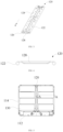
FIG. 1 is a first schematic view of the structure of an electromagnetic heating device according to an embodiment of the present application; -
FIG. 2 is a second schematic view of the structure of an electromagnetic heating device according to an embodiment of the present application; -
FIG. 3 is a first schematic view of the structure of a support beam according to an embodiment of the present application; -
FIG. 4 is a second schematic view of the structure of a support beam according to an embodiment of the present application; -
FIG. 5 is a third schematic view of the structure of an electromagnetic heating device according to an embodiment of the present application; -
Figure 6 is a cross sectional view of the electromagnetic heating device in the embodiment shown inFIG. 5 taken along the direction A-A; and -
Figure 7 is a cross sectional view of the electromagnetic heating device in the embodiment shown inFIG. 5 taken along the direction B-B. - And, the corresponding relationships between the reference signs and the component names in
FIG. 1 to FIG. 7 are as follows:
100 electromagnetic heating device, 110 frame, 112 first edge, 114 second edge, 120 support beam, 122 folded edge, 124 mounting hole, 126 positioning hole, 128 groove, 130 coil disc, 140 limiting platform, 142 positioning column, 150 bottom plate. - To more clearly understand the above purposes, features and advantages of the present application, the present application will be further detailed hereinafter in combination with the accompanying drawings and embodiments. It should be indicated that in the case of no conflict, the embodiments and the features in the embodiments of the present application can be combined with each other.
- Many details are illustrated in the following description for the convenience of a thorough understanding to the present application, but the present application can further be implemented using other embodiments other than these described herein. Therefore, the protection scope of the present application is not limited to the specific embodiments disclosed in the following text.
- The electromagnetic heating device according to some embodiments of the present application will be described hereinafter referring to
FIG. 1 to FIG. 7 . - As shown in
FIG. 1 and FIG. 2 , an embodiment of the present application provides anelectromagnetic heating device 100, and theelectromagnetic heating device 100 comprises: aframe 110, and theframe 110 has an annular shape; asupport beam 120, and thesupport beam 120 is disposed inside of theframe 110, and both of the two ends of thesupport 120 are connected to theframe 110; and acoil disc 130, with one end connected to theframe 110, and the other end connected to thesupport beam 120. - The
electromagnetic heating device 100 defined in the present application comprises theframe 110 and thecoil disc 130. Specifically, theframe 110 serves as the structure of themain frame 110 of theelectromagnetic heating device 100, and is configured to position and support other functional components of theelectromagnetic heating device 100. And, theframe 110 has an annular shape, and the functional components are arranged on the inner side of theframe 110. Thecoil disc 130 is installed on the inner side of theframe 110. Once powered on, thecoil disc 130 can generate an electromagnetic field. Under the effect of the electromagnetic field, a target container gradually heats up, and then the food ingredients contained inside are heated by the high temperature target container to cook finished food. When theelectromagnetic heating device 100 is a multi-head stove, there are a plurality ofcoil discs 130, and the plurality ofcoil discs 130 need to be fixed at different predetermined installation positions within theframe 110 respectively. - In related art, it is necessary to first install a horizontally-placed mounting plate inside a housing. Subsequently, the coil disc is placed above the mounting plate and the mounting plate can support and position the coil disc. However, the mounting plate that covers the entire internal space is relatively large in size, then consumes a large amount of materials, and then this leads to an increase in the product cost. Moreover, the mounting plate significantly increases the weight of the product, which is not conducive to the lightweight design of the product, thus affecting product practicality.
- In response to this, the
electromagnetic heating device 100 defined in the present application is provided with asupport beam 120. Thesupport beam 120 is installed on the inner side of theframe 110, with both ends of thesupport beam 120 fixed to theframe 110. After assembly, thesupport beam 120 is horizontally arranged within the inner space of theframe 110. Based on this, the first end of thecoil disc 130 is connected to theframe 110, and the second end of thecoil disc 130 is connected to thesupport beam 120. After the installation of thecoil disc 130 is completed, the two ends of thecoil disc 130 are respectively supported by theframe 110 and thesupport beam 120, and the middle section of thecoil disc 130 is suspended, and thecoil disc 130 is jointly supported by theframe 110 and thesupport beam 120. - Thus, by arranging the
support beam 120, the present application can reduce the material usage of the positioning and installing structures while meet the positioning requirements of thecoil disc 130, to reduce the cost and weight of theelectromagnetic heating device 100. Moreover, compared with the embodiment of securing and installing a plate member on the inner side of theframe 110, installing thesupport beam 120 on the inner side of theframe 110 is less difficult, and can reduce the complexity of the assembly structure, to further lower the process complexity and production cost of theelectromagnetic heating device 100. As a result, the technical defects of high product weight and high cost existing in related art are overcome. Furthermore, the technical effects of optimizing the positioning structure of thecoil disc 130, enhancing the practicality of theelectromagnetic heating device 100, reducing the cost of theelectromagnetic heating device 100, and improving the market competitiveness of the product are achieved. - Specifically, the extension direction of the
support beam 120 on the inner side of theframe 110 and the number of thesupport beam 120 installed inside on the inner side of theframe 110 can be adjusted in a targeted manner according to the distribution requirements of thecoil disc 130 and the size of thecoil disc 130. For this, this embodiment does not impose rigid restrictions on the number of thesupport beam 120 and the extension direction of thesupport beam 120. It only needs to meet the basic requirement of jointly positioning thecoil disc 130 in cooperation with theframe 110. - As shown in
FIG. 1, FIG. 2 andFIG. 5 , in some embodiments, theframe 110 comprises: twofirst edges 112, and the twofirst edges 112 are spaced apart from each other, and the two ends of thesupport beam 120 are connected to the twofirst edges 112 respectively; twosecond edges 114, and the twosecond edges 114 are spaced apart from each other, and thefirst edges 112 and thesecond edges 114 connected end to end and enclose aframe 110. - In this embodiment, the
frame 110 is rectangular, and therectangular frame 110 is enclosed by twofirst edges 112 and twosecond edges 114. And, the twofirst edges 112 are arranged parallel and opposite to each other, the two ends of onesecond edge 114 are connected to the first ends of the twofirst edges 112, and the two ends of the othersecond edge 114 are connected to the second ends of the twofirst edges 112, thus enclosing arectangular frame 110 through thefirst edges 112 and thesecond edges 114 connected end to end. The two ends of thesupport beam 120 are connected to the twofirst edges 112 respectively, to divide the space on both sides of thesupport beam 120 that can be used for positioning and installing thecoil disc 130. Specifically, thecoil discs 130 arranged on the left and right sides of thesupport beam 120 can connect the first ends to thefirst edges 112 and connect the second ends to thesupport beam 120, and can further connect the first ends of thecoil discs 130 to thesecond edges 114 and connect the second ends to thesupport beam 120. For this, this embodiment does not impose rigid restrictions on the installation method for thecoil disc 130, and it only needs to meet the requirements that thecoil discs 130 are distributed on both sides of the support beam and jointly supported by thesupport beam 120 and theframe 110. - By connecting the two ends of the
support beam 120 to the two opposite edges of therectangular frame 110 respectively, when theelectromagnetic heating device 100 comprises a plurality ofcoil discs 130, it provides convenient conditions for arranging thecoil discs 130 in an array, to form multiple regular and evenly distributed heating areas. Compared with the embodiment of connecting two adjacent edges with thesupport beam 120, this installation method for thesupport beam 120 can enhance the strength of the overall structure composed of theframe 110 and thesupport beam 120, and reduce the possibility of the deformation of therectangular frame 110 during the installation of thecoil discs 130 or the operation process. Consequently, the technical effects of reducing the difficulty of the arrangement of thecoil disc 130 and improving the reliability of theelectromagnetic heating device 100 are achieved. - In some embodiments, the
support beam 120 is spaced apart from thesecond edges 114; one end of thecoil disc 130 is connected to thesupport beam 120, and the other end is connected to the second edges 114. - In this embodiment, following the previous embodiment, the
first edges 112 are the long edges of therectangular frame 110, and thesecond edges 114 are the short edges of therectangular frame 110. Thesupport beam 120 is fixed between the twofirst edges 112, and is spaced apart from the twosecond edges 114. Based on this, one end of thecoil disc 130 is fixed to thesecond edges 114, and the other end is fixed to thesupport beam 120, and the middle section of thecoil disc 130 is suspended between thesecond edges 114 and thesupport beam 120. Evidently, this layout allows thecoil disc 130 to be horizontally placed between the short edges of therectangular frame 110 and thesupport beam 120. As a result, thesupport beam 120 can effectively support thecoil discs 130 on both the left and right sides simultaneously, to increase the number ofcoil discs 130 that can be arranged in theelectromagnetic heating device 100. This makes the structure more suitable for the multi-head stove. - In some embodiments, two
coil discs 130 form a group, and the twocoil discs 130 in the same group are symmetrically distributed. - In this embodiment, two
coil discs 130 are grouped together, and the installation method for the twocoil discs 130 in the same group is described. Specifically, the twocoil discs 130 in the same group are symmetrically distributed on the left and right sides of thesupport beam 120. And, onecoil disc 130 is connected to thesecond edge 114 on the left side of thesupport beam 120, and theother coil disc 130 is connected to thesecond edge 114 on the right side of thesupport beam 120. This arrangement can create heating areas that are symmetrically distributed on the left and right sides of theelectromagnetic heating device 100, similar to a conventional stove, and thus this provides convenient conditions for users to cook food simultaneously above the two heating areas. Consequently, the technical effects of enhancing the arrangement compactness of thecoil discs 130, improving the practicality of theelectromagnetic heating device 100, and enhancing the user experience are achieved. - In some embodiments, the
electromagnetic heating device 100 comprises a plurality of groups ofcoil discs 130, and the plurality of groups ofcoil discs 130 are distributed along the extension direction (inFIG. 1 andFIG. 3 , shown by arrow a) of thesupport beam 120. - In this embodiment, following the previous embodiment, the
electromagnetic heating device 100 comprises a plurality of groups ofcoil discs 130, and the plurality of groups ofcoil discs 130 are distributed along the extension direction of thesupport beam 120 to form an array on theelectromagnetic heating device 100. The number of rows in this array corresponds to the number of groups of thecoil discs 130, while the number of columns remains constant at two. This layout maximizes the utilization of the space at the internal side of therectangular frame 110, to increase the number ofcoil discs 130 without altering the size of theframe 110. Consequently, the technical effects of enhancing the structural compactness of theelectromagnetic heating device 100 and providing convenient conditions for the miniaturized design of theelectromagnetic heating device 100. - As shown in
FIG. 2 andFIG. 5 , in some embodiments, thecoil discs 130 are located on the top of thesupport beam 120, and thesupport beam 120 is configured to support thecoil discs 130. - In this embodiment, the support manner provided by the
support beam 120 is explicitly defined. Specifically, the end portion of thecoil disc 130 is placed on the support beam, to support thecoil disc 130 through thesupport beam 120 and prevent thecoil disc 130 from collapsing due to its own weight. Correspondingly, the other end of thecoil disc 130 is placed on theframe 110, and then thecoil disc 130 is jointly supported by theframe 110 and thesupport beam 120. Compared with the connection manner of end-to end, placing thecoil disc 130 on thesupport beam 120 can enhance the positioning reliability of thecoil disc 130 and avoid the problem of damaging the end-to-end structure due to the self-weight of thecoil disc 130. Furthermore, during assembly, thecoil disc 130 can be first placed on thesupport beam 120 and theframe 110, and then moved to a predetermined position before conducting connection. Compared with the connection manner of nd-to-end, this structural layout provided in this embodiment can reduce disassembly and assembly complexity of thecoil disc 130, then improve the production efficiency of the electromagnetic heating device and lower the maintenance difficulty of the electromagnetic heating device. - As shown in
FIG. 3, FIG. 4 ,FIG. 6 and FIG. 7 , in some embodiments, thesupport beam 120 is a plate member. The long edge of thesupport beam 120 bends in the direction away from thecoil disc 130, and forms a foldededge 122. - In this embodiment, the
support beam 120 is a plate member, and specifically, thesupport beam 120 can be manufactured through a casting or stamping process. And, the long edges of thesupport beam 120, namely the left and right side edges of thesupport beam 120, bend in the direction away from thecoil disc 130. Taking the previous embodiment of placing thecoil disc 130 on thesupport beam 120 as an example, the left and right long edges of thesupport beam 120 bend towards the bottom to form a foldededge 122 that is in line with the extension direction of thesupport beam 120. - By constructing a folded
edge 122, the bending and torsional resistance of thesupport beam 120 can be enhanced. This prevents thesupport beam 120 from bending or even breaking under the gravity of plurality ofcoil discs 130, to achieve the technical effects of increasing the structural strength of thesupport beam 120, improving the reliability of the electromagnetic heating device, and reducing the product failure rate. - In some embodiments, when the
support beam 120 is sectioned by a plane perpendicular to the direction of its extension direction, the foldededge 122 appears to be circular in the cross section. - In this embodiment, the shape of the folded
edge 122 is defined. Specifically, when thesupport beam 120 is sectioned by a plane perpendicular to its extension direction, a cross section of thesupport beam 120 can be obtained. In this cross section, the foldededges 122 bending downward at both ends of thesupport beam 120 are circular, to form column-shaped folded edges 122. The possibility of stress concentration on the column-shaped foldededges 122 is relatively low, by defining the shapes of the cross sections of the foldededges 122 to be circular, the bending and torsional resistance of the foldededges 122 can be further enhanced to ensure that thesupport beam 120 can bear the weight of plurality ofcoil discs 130. Thus, the technical effects of improving the structural strength of thesupport beam 120 and reducing its failure rate are achieved. - In some embodiments, the diameters of the folded
edges 122 are greater than or equal to 6mm while less than or equal to 12mm. - In this embodiment, the size of the column-shaped folded
edge 122 is defined. Specifically, the diameter of the column-shaped foldededge 122 should be greater than or equal to 6mm. Limiting the diameter of the column-shaped foldededge 122 to be greater than or equal to 6mm can avoid that the column-shaped foldededge 122 with a too small size cannot bear the weight of plurality ofcoil discs 130, thus preventing thesupport beam 120 from bending or even breaking. - Furthermore, the diameter of the column-shaped folded
edge 122 further needs to be less than or equal to 12mm. Limiting the diameter of the column-shaped foldededge 122 to be less than or equal to 12mm can reduce the occupation of the space below thesupport beam 120 by the column-shaped foldededge 122 on the basis of meeting the need of bending and torsional resistance, and the possibility of interference between the column-shaped foldededge 122 and the electrical structure at the bottom can be decreased, thus avoiding the forced increase in product size due to the overly large size of the foldededge 122. At the same time, limiting the diameter of the column-shaped foldededge 122 to be less than or equal to 12mm can further reduce material usage and reduce the self-weight and cost of thesupport beam 120. As a result, the technical effects of improving the reliability of thesupport beam 120, reducing its production cost, and providing convenient conditions for the miniaturized and lightweight design of theelectromagnetic heating device 100 are achieved. - In some embodiments, the
support beam 120 comprises a mountinghole 124, and thecoil disc 130 is partially inserted into the mountinghole 124. - In this embodiment, the
support beam 120 is provided with the mountinghole 124 penetrating vertically through thesupport beam 120, and a protrusion with a shape matching the mountinghole 124 is correspondingly provided on the bottom of thecoil disc 130. During assembling thecoil disc 130, the protrusion is aligned with and inserted into the mountinghole 124. Correspondingly, an inserting hole is further disposed in theframe 110, into which the protrusion at the bottom of the other end of thecoil disc 130 is inserted, to precisely locate thecoil disc 130 at a predetermined mounting position. This positioning structure has the advantage of low complexity and convenient disassembling and assembling, and can significantly reduce the assembly complexity and maintenance difficulty of thecoil disc 130. - Furthermore, the protrusion has an interference fit with the mounting
hole 124 in thesupport beam 120, and further has an interference fit with the inserting hole in theframe 110. By setting this interference fit relationship, it is possible to prevent the misalignment of thecoil disc 130 during operation and avoid abnormal noises from thecoil disc 130. Thus, the technical effect of improving the positioning accuracy of thecoil disc 130 is achieved. - As shown in
FIG. 3, FIG. 5 ,FIG. 6 and FIG. 7 , in some embodiments, theelectromagnetic heating device 100 further comprises: a limitingplatform 140 connected to theframe 110; apositioning column 142 arranged on the limitingplatform 140; and a positioning hole 126 arranged in thesupport beam 120 and sleeved on thepositioning column 142, and thesupport beam 120 abuts against the limitingplatform 140. - In this embodiment, the connection structure between the
support beam 120 and theframe 110 is described. Specifically, a limitingplatform 140 is provided on the inner annular surface of theframe 110, and apositioning column 142 is arranged on the top of the limitingplatform 140. Correspondingly, a positioning hole 126 with a size matching thepositioning column 142 is provided in the end portion of thesupport beam 120. During the assembly process, the positioning hole 126 is aligned with thepositioning column 142 and then thesupport beam 120 is pressed down, and thesupport beam 120 is sleeved on thepositioning column 142 until the bottom surface of thesupport beam 120 abuts against the upper end surface of the limitingplatform 140, thus completing the pre-assembly of thesupport beam 120. Subsequently, thesupport beam 120 is fixed on the limitingplatform 140 with a connecting member such as a screw. - Compared with the embodiment where the
support beam 120 is connected at its ends to the inner side of theframe 110, the limitingplatform 140 can provide support for thesupport beam 120, thus preventing thesupport beam 120, which bears the weight of thecoil disc 130, from falling off theframe 110. Meanwhile, this structure has the advantages of low structural complexity and easy disassembly and assembly, which is conducive to improving production efficiency and reducing maintenance difficulty. - In some embodiments, the
support beam 120 comprises agroove 128, and the positioning hole 126 is located in thegroove 128. - In this embodiment, a
groove 128 is provided in the end portion of thesupport beam 120, and thegroove 128 is recessed in the direction away from thecoil disc 130. Thegroove 128 can be formed by stamping. On this basis, the positioning hole 126 is provided in thegroove 128, that is, the contact area between the limitingplatform 140 and thesupport beam 120 is at the bottom of thegroove 128. By setting thesunken groove 128, the structural strength of the part of thesupport beam 120 in contact with the limitingplatform 140 can be improved. The inclined side walls of thegroove 128 can bear the weight of thecoil disc 130, to reduce the possibility of the collapsing of thesupport beam 120. Thus, the technical effects of optimizing the structural strength of thesupport beam 120 and improving the reliability of theelectromagnetic heating device 100 are achieved. - As shown in
FIG. 5 andFIG. 6 , in some embodiments, theelectromagnetic heating device 100 further comprises abottom plate 150 connected to theframe 110. Thebottom plate 150 is located at the bottom of thesupport beam 120 and thecoil disc 130. - In this embodiment, the
electromagnetic heating device 100 is further provided with abottom plate 150, and thebottom plate 150 is connected to theframe 110 and configured to cover the opening in the bottom of theannular frame 110. Theframe 110 and thebottom plate 150 enclose a cavity, and electrical members such as a controller and a circuit board are placed in the cavity, to protect the electrical members by thebottom plate 150 and theframe 110, and reduce the probability of the damage of the electrical members. - In some embodiments, the
bottom plate 150 is spaced apart from thesupport beam 120, and thebottom plate 150 is further spaced apart from thecoil disc 130. - In this embodiment, the
bottom plate 150 is spaced apart from thesupport beam 120, and thecoil disc 130 is spaced apart from thebottom plate 150. That is, the middle sections of thesupport beam 120 and the coil disc are 130 suspended. Under this structural layout, there is an installation space under thesupport beam 120 and thecoil disc 130, where the power supply circuit and control circuit connected to thecoil disc 130 can be arranged. Consequently, the technical effects of improving the structural compactness of theelectromagnetic heating device 100 and reducing its size are achieved. - In some embodiments, the
electromagnetic heating device 100 further comprises a panel connected to theframe 110 and located on the top of thecoil disc 130. - In this embodiment, the
electromagnetic heating device 100 further comprises a panel, which is placed on the top of thecoil disc 130. Firstly, the panel is configured to cover the opening in the top of theframe 110 to hide the functional components inside theframe 110, and secondly, the panel is configured to support a target container. Thecoil disc 130 inside theframe 110 creates a heating area on the panel. When the target container is placed above the heating area, under the action of the electromagnetic field generated by thecoil disc 130, the target container gradually heats up, to cook the food ingredients inside it at a high temperature. - It needs to be indicated that in the claims, specification and accompanying drawings of the present application, the term of "a plurality of" refers to two or more than two, unless otherwise clearly defined. The orientation or position relations indicated by the terms of "upper", "lower" and the like are based on the orientation or position relations shown in the accompanying drawings, and are just intended to conveniently describe the present application and simplify the description, and are not intended to indicate or imply that the devices or units as indicated should have specific orientations or should be configured or operated in specific orientations, and then such description should not be construed as limitations to the present application. The terms "connect", "mount", "fix" and the like should be understood in a broad sense, for example, the term "connect" can be a fixed connection between a plurality of objects, a detachable connection between a plurality of objects, or an integral connection; it can be a direct connection between a plurality of objects, or an indirect connection between a plurality of objects through an intermediate medium. For those of ordinary skills in this field, the specific meanings of the above terms in the present application can be understood according to the specific situations of the above data.
- In the claims, the description and the accompanying drawings of the description of the present application, the description of the terms of "an embodiment", "some embodiments", "specific embodiment" and the like is intended to mean that the specific features, structures, materials or characteristics described in combination with the embodiments or examples are comprised in at least one embodiment or example of the present application. In the claims, the description and the accompanying drawings of the description, the illustrative expression of the above terms may not indicate the same embodiment or example. In addition, the specific features, structures, materials or characteristics as described may be combined with each other in an appropriate method in one or more of any embodiments or examples.
- The above-mentioned are merely some embodiments of the present application and not intended to limit the present application, and for one skilled in the art, various modifications and changes may be made to the present application. Any modifications, equivalent substitutions, improvements and so on made within the spirit and principle of the present application should be covered within the scope of protection of the present application.
Claims (15)
- An electromagnetic heating device, comprising:a frame, wherein the frame has an annular shape;a support beam, disposed inside of the frame, wherein both of two ends of the support beam are connected to the frame; anda coil disc, with one end connected to the frame, and an other end connected to the support beam.
- The electromagnetic heating device according to claim 1, wherein, the frame comprises:two first edges, wherein the two first edges are spaced apart from each other, and the two ends of the support beam are connected to the two first edges respectively; andtwo second edges, wherein the two second edges are spaced apart from each other, and the first edges and the second edges are connected end to end and enclose the frame.
- The electromagnetic heating device according to claim 2, wherein,the support beam is spaced apart from the second edges;one end of the coil disc is connected to the support beam, and the other end is connected to the second edges.
- The electromagnetic heating device according to claim 3, wherein,
two coil discs form a group, and the two coil discs in the same group are symmetrically distributed. - The electromagnetic heating device according to claim 4, wherein, the electromagnetic heating device comprises a plurality of groups of coil discs which are distributed along an extension direction of the support beam.
- The electromagnetic heating device according to claim 1, wherein, the coil discs are located on a top of the support beam, and the support beam is configured to support the coil discs.
- The electromagnetic heating device according to claim 6, wherein, the support beam is a plate member, and a long edge of the support beam bends in a direction away from the coil disc, and forms a folded edge.
- The electromagnetic heating device according to claim 7, wherein, when the support beam is sectioned by a plane perpendicular to the extension direction of the support beam, the folded edge appears to be circular in a cross section.
- The electromagnetic heating device according to claim 8, wherein, a diameter of the folded edge is greater than or equal to 6mm while less than or equal to 12mm.
- The electromagnetic heating device according to claim 7, wherein, the support beam comprises a mounting hole, and the coil disc is partially inserted into the mounting hole.
- The electromagnetic heating device according to claim 7, further comprising:a limiting platform connected to the frame;a positioning column arranged on the limiting platform; anda positioning hole arranged in the support beam and sleeved on the positioning column, wherein the support beam abuts against the limiting platform.
- The electromagnetic heating device according to claim 11, wherein, the support beam comprises a groove, and the positioning hole is located in the groove.
- The electromagnetic heating device according to any one of claims 1 to 12, further comprising:
a bottom plate connected to the frame, wherein the bottom plate is located at a bottom of the support beam and the coil disc. - The electromagnetic heating device according to claim 13, wherein,the bottom plate is spaced apart from the support beam; andthe bottom plate is spaced apart from the coil disc.
- The electromagnetic heating device according to claim 13, further comprising:
a panel connected to the frame and located on a top of the coil disc.
Applications Claiming Priority (2)
| Application Number | Priority Date | Filing Date | Title |
|---|---|---|---|
| CN202222333225.1U CN218495034U (en) | 2022-09-02 | 2022-09-02 | Electromagnetic heating equipment |
| PCT/CN2023/115730 WO2024046349A1 (en) | 2022-09-02 | 2023-08-30 | Electromagnetic heating device |
Publications (2)
| Publication Number | Publication Date |
|---|---|
| EP4579133A1 true EP4579133A1 (en) | 2025-07-02 |
| EP4579133A4 EP4579133A4 (en) | 2025-12-24 |
Family
ID=85189039
Family Applications (1)
| Application Number | Title | Priority Date | Filing Date |
|---|---|---|---|
| EP23859378.4A Pending EP4579133A4 (en) | 2022-09-02 | 2023-08-30 | ELECTROMAGNETIC HEATING DEVICE |
Country Status (4)
| Country | Link |
|---|---|
| EP (1) | EP4579133A4 (en) |
| KR (1) | KR20250051763A (en) |
| CN (1) | CN218495034U (en) |
| WO (1) | WO2024046349A1 (en) |
Families Citing this family (1)
| Publication number | Priority date | Publication date | Assignee | Title |
|---|---|---|---|---|
| CN218495034U (en) * | 2022-09-02 | 2023-02-17 | 佛山市顺德区美的电热电器制造有限公司 | Electromagnetic heating equipment |
Family Cites Families (13)
| Publication number | Priority date | Publication date | Assignee | Title |
|---|---|---|---|---|
| DE2619622C3 (en) * | 1976-05-04 | 1981-04-30 | Steinmetz, Manfred, 2105 Seevetal | Infrared radiation system |
| JPH10335056A (en) * | 1997-05-30 | 1998-12-18 | Fuji Mac:Kk | Electromagnetic induction heating coil |
| DE202009000990U1 (en) * | 2009-01-27 | 2009-03-26 | BSH Bosch und Siemens Hausgeräte GmbH | Induction coil support device |
| KR101331254B1 (en) * | 2010-08-31 | 2013-11-19 | 주식회사 디알하이텍 | Heating apparatus using antibiotic nano element natural stone panel and sauna apparatus having the same |
| CN202979351U (en) * | 2012-09-10 | 2013-06-05 | 美的集团股份有限公司 | Electromagnetic heater and electromagnetic heating coil panel |
| DE102013211300B4 (en) * | 2013-06-17 | 2017-01-05 | E.G.O. Elektro-Gerätebau GmbH | hob |
| CN203457359U (en) * | 2013-07-31 | 2014-02-26 | 美的集团股份有限公司 | Coil panel and induction cooker having same |
| WO2017020964A1 (en) * | 2015-08-06 | 2017-02-09 | Arcelik Anonim Sirketi | Improved mounting assembly for use in a cooking appliance |
| CN107872940A (en) * | 2016-09-28 | 2018-04-03 | 泰州市润扬电气有限公司 | The two-fold a variety of overlapping mode mounting rails of flanging |
| JP6917576B2 (en) * | 2017-10-13 | 2021-08-11 | パナソニックIpマネジメント株式会社 | Cooker |
| DE102018120740A1 (en) * | 2018-08-24 | 2019-02-14 | Schott Ag | Cooking appliances with increased ease of use, intuitive controls and improved user safety |
| CN212936240U (en) * | 2020-09-10 | 2021-04-09 | 佛山市顺德区美的电热电器制造有限公司 | Coil disc assembly and electromagnetic heating device |
| CN218495034U (en) * | 2022-09-02 | 2023-02-17 | 佛山市顺德区美的电热电器制造有限公司 | Electromagnetic heating equipment |
-
2022
- 2022-09-02 CN CN202222333225.1U patent/CN218495034U/en active Active
-
2023
- 2023-08-30 WO PCT/CN2023/115730 patent/WO2024046349A1/en not_active Ceased
- 2023-08-30 EP EP23859378.4A patent/EP4579133A4/en active Pending
- 2023-08-30 KR KR1020257009440A patent/KR20250051763A/en active Pending
Also Published As
| Publication number | Publication date |
|---|---|
| CN218495034U (en) | 2023-02-17 |
| WO2024046349A1 (en) | 2024-03-07 |
| KR20250051763A (en) | 2025-04-17 |
| EP4579133A4 (en) | 2025-12-24 |
Similar Documents
| Publication | Publication Date | Title |
|---|---|---|
| JP3216203U (en) | LED light panel assembly | |
| EP2285198B1 (en) | Modular building block type chassis | |
| CN218495034U (en) | Electromagnetic heating equipment | |
| CN108563303A (en) | A kind of device for fixing hard disk | |
| CN219658311U (en) | Backlight module and display device | |
| CN203457359U (en) | Coil panel and induction cooker having same | |
| CN213636272U (en) | Installation fixing device of high density cross antenna | |
| CN221055145U (en) | Compressor drive plate mounting structure | |
| CN206472018U (en) | A kind of polycrystalline pipe fixation press strip and power inverter | |
| CN209435671U (en) | It is a kind of for integrated electric cabinet plug-in unit box body | |
| CN217158517U (en) | Battery module | |
| CN224266653U (en) | Support mechanism for MEMS baking device and MEMS baking device | |
| CN214504328U (en) | Embedded computer motherboard structure | |
| CN215187699U (en) | Novel high-utilization-rate opposite-sex cavity structure | |
| CN211557772U (en) | Circuit board convenient to installation is fixed | |
| CN221197842U (en) | Heat preservation heating type battery clamp | |
| CN201355652Y (en) | electrical connector | |
| CN223350053U (en) | Oven box structure and oven | |
| CN219019419U (en) | Circuit board box and gas stove | |
| CN216752513U (en) | PLC controller convenient to dismouting | |
| CN221071699U (en) | Novel electroplating roller of thick film flaky patch fuse | |
| CN219494807U (en) | Ceramic part sintering jig | |
| CN223679675U (en) | Expressway intelligent lane controller box device | |
| CN219759344U (en) | Encapsulating reactor | |
| CN213462709U (en) | Mounting structure for circuit board |
Legal Events
| Date | Code | Title | Description |
|---|---|---|---|
| STAA | Information on the status of an ep patent application or granted ep patent |
Free format text: STATUS: THE INTERNATIONAL PUBLICATION HAS BEEN MADE |
|
| PUAI | Public reference made under article 153(3) epc to a published international application that has entered the european phase |
Free format text: ORIGINAL CODE: 0009012 |
|
| STAA | Information on the status of an ep patent application or granted ep patent |
Free format text: STATUS: REQUEST FOR EXAMINATION WAS MADE |
|
| 17P | Request for examination filed |
Effective date: 20250325 |
|
| AK | Designated contracting states |
Kind code of ref document: A1 Designated state(s): AL AT BE BG CH CY CZ DE DK EE ES FI FR GB GR HR HU IE IS IT LI LT LU LV MC ME MK MT NL NO PL PT RO RS SE SI SK SM TR |
|
| REG | Reference to a national code |
Ref country code: DE Ref legal event code: R079 Free format text: PREVIOUS MAIN CLASS: F24C0007060000 Ipc: H05B0006120000 |
|
| DAV | Request for validation of the european patent (deleted) | ||
| DAX | Request for extension of the european patent (deleted) | ||
| A4 | Supplementary search report drawn up and despatched |
Effective date: 20251124 |
|
| RIC1 | Information provided on ipc code assigned before grant |
Ipc: H05B 6/12 20060101AFI20251118BHEP |