EP4579117A1 - Display device - Google Patents
Display device Download PDFInfo
- Publication number
- EP4579117A1 EP4579117A1 EP24175093.4A EP24175093A EP4579117A1 EP 4579117 A1 EP4579117 A1 EP 4579117A1 EP 24175093 A EP24175093 A EP 24175093A EP 4579117 A1 EP4579117 A1 EP 4579117A1
- Authority
- EP
- European Patent Office
- Prior art keywords
- weight
- display device
- case
- weights
- hole
- Prior art date
- Legal status (The legal status is an assumption and is not a legal conclusion. Google has not performed a legal analysis and makes no representation as to the accuracy of the status listed.)
- Pending
Links
Images









Classifications
-
- F—MECHANICAL ENGINEERING; LIGHTING; HEATING; WEAPONS; BLASTING
- F16—ENGINEERING ELEMENTS AND UNITS; GENERAL MEASURES FOR PRODUCING AND MAINTAINING EFFECTIVE FUNCTIONING OF MACHINES OR INSTALLATIONS; THERMAL INSULATION IN GENERAL
- F16M—FRAMES, CASINGS OR BEDS OF ENGINES, MACHINES OR APPARATUS, NOT SPECIFIC TO ENGINES, MACHINES OR APPARATUS PROVIDED FOR ELSEWHERE; STANDS; SUPPORTS
- F16M11/00—Stands or trestles as supports for apparatus or articles placed thereon ; Stands for scientific apparatus such as gravitational force meters
- F16M11/20—Undercarriages with or without wheels
- F16M11/22—Undercarriages with or without wheels with approximately constant height, e.g. with constant length of column or of legs
-
- F—MECHANICAL ENGINEERING; LIGHTING; HEATING; WEAPONS; BLASTING
- F16—ENGINEERING ELEMENTS AND UNITS; GENERAL MEASURES FOR PRODUCING AND MAINTAINING EFFECTIVE FUNCTIONING OF MACHINES OR INSTALLATIONS; THERMAL INSULATION IN GENERAL
- F16M—FRAMES, CASINGS OR BEDS OF ENGINES, MACHINES OR APPARATUS, NOT SPECIFIC TO ENGINES, MACHINES OR APPARATUS PROVIDED FOR ELSEWHERE; STANDS; SUPPORTS
- F16M11/00—Stands or trestles as supports for apparatus or articles placed thereon ; Stands for scientific apparatus such as gravitational force meters
- F16M11/02—Heads
- F16M11/04—Means for attachment of apparatus; Means allowing adjustment of the apparatus relatively to the stand
-
- H—ELECTRICITY
- H05—ELECTRIC TECHNIQUES NOT OTHERWISE PROVIDED FOR
- H05K—PRINTED CIRCUITS; CASINGS OR CONSTRUCTIONAL DETAILS OF ELECTRIC APPARATUS; MANUFACTURE OF ASSEMBLAGES OF ELECTRICAL COMPONENTS
- H05K5/00—Casings, cabinets or drawers for electric apparatus
- H05K5/02—Details
- H05K5/0217—Mechanical details of casings
- H05K5/0234—Feet; Stands; Pedestals, e.g. wheels for moving casing on floor
-
- F—MECHANICAL ENGINEERING; LIGHTING; HEATING; WEAPONS; BLASTING
- F16—ENGINEERING ELEMENTS AND UNITS; GENERAL MEASURES FOR PRODUCING AND MAINTAINING EFFECTIVE FUNCTIONING OF MACHINES OR INSTALLATIONS; THERMAL INSULATION IN GENERAL
- F16M—FRAMES, CASINGS OR BEDS OF ENGINES, MACHINES OR APPARATUS, NOT SPECIFIC TO ENGINES, MACHINES OR APPARATUS PROVIDED FOR ELSEWHERE; STANDS; SUPPORTS
- F16M11/00—Stands or trestles as supports for apparatus or articles placed thereon ; Stands for scientific apparatus such as gravitational force meters
- F16M11/02—Heads
- F16M11/04—Means for attachment of apparatus; Means allowing adjustment of the apparatus relatively to the stand
- F16M11/043—Allowing translations
- F16M11/046—Allowing translations adapted to upward-downward translation movement
-
- F—MECHANICAL ENGINEERING; LIGHTING; HEATING; WEAPONS; BLASTING
- F16—ENGINEERING ELEMENTS AND UNITS; GENERAL MEASURES FOR PRODUCING AND MAINTAINING EFFECTIVE FUNCTIONING OF MACHINES OR INSTALLATIONS; THERMAL INSULATION IN GENERAL
- F16M—FRAMES, CASINGS OR BEDS OF ENGINES, MACHINES OR APPARATUS, NOT SPECIFIC TO ENGINES, MACHINES OR APPARATUS PROVIDED FOR ELSEWHERE; STANDS; SUPPORTS
- F16M11/00—Stands or trestles as supports for apparatus or articles placed thereon ; Stands for scientific apparatus such as gravitational force meters
- F16M11/02—Heads
- F16M11/04—Means for attachment of apparatus; Means allowing adjustment of the apparatus relatively to the stand
- F16M11/06—Means for attachment of apparatus; Means allowing adjustment of the apparatus relatively to the stand allowing pivoting
- F16M11/08—Means for attachment of apparatus; Means allowing adjustment of the apparatus relatively to the stand allowing pivoting around a vertical axis, e.g. panoramic heads
-
- F—MECHANICAL ENGINEERING; LIGHTING; HEATING; WEAPONS; BLASTING
- F16—ENGINEERING ELEMENTS AND UNITS; GENERAL MEASURES FOR PRODUCING AND MAINTAINING EFFECTIVE FUNCTIONING OF MACHINES OR INSTALLATIONS; THERMAL INSULATION IN GENERAL
- F16M—FRAMES, CASINGS OR BEDS OF ENGINES, MACHINES OR APPARATUS, NOT SPECIFIC TO ENGINES, MACHINES OR APPARATUS PROVIDED FOR ELSEWHERE; STANDS; SUPPORTS
- F16M11/00—Stands or trestles as supports for apparatus or articles placed thereon ; Stands for scientific apparatus such as gravitational force meters
- F16M11/02—Heads
- F16M11/04—Means for attachment of apparatus; Means allowing adjustment of the apparatus relatively to the stand
- F16M11/06—Means for attachment of apparatus; Means allowing adjustment of the apparatus relatively to the stand allowing pivoting
- F16M11/10—Means for attachment of apparatus; Means allowing adjustment of the apparatus relatively to the stand allowing pivoting around a horizontal axis
-
- F—MECHANICAL ENGINEERING; LIGHTING; HEATING; WEAPONS; BLASTING
- F16—ENGINEERING ELEMENTS AND UNITS; GENERAL MEASURES FOR PRODUCING AND MAINTAINING EFFECTIVE FUNCTIONING OF MACHINES OR INSTALLATIONS; THERMAL INSULATION IN GENERAL
- F16M—FRAMES, CASINGS OR BEDS OF ENGINES, MACHINES OR APPARATUS, NOT SPECIFIC TO ENGINES, MACHINES OR APPARATUS PROVIDED FOR ELSEWHERE; STANDS; SUPPORTS
- F16M11/00—Stands or trestles as supports for apparatus or articles placed thereon ; Stands for scientific apparatus such as gravitational force meters
- F16M11/02—Heads
- F16M11/04—Means for attachment of apparatus; Means allowing adjustment of the apparatus relatively to the stand
- F16M11/06—Means for attachment of apparatus; Means allowing adjustment of the apparatus relatively to the stand allowing pivoting
- F16M11/12—Means for attachment of apparatus; Means allowing adjustment of the apparatus relatively to the stand allowing pivoting in more than one direction
-
- F—MECHANICAL ENGINEERING; LIGHTING; HEATING; WEAPONS; BLASTING
- F16—ENGINEERING ELEMENTS AND UNITS; GENERAL MEASURES FOR PRODUCING AND MAINTAINING EFFECTIVE FUNCTIONING OF MACHINES OR INSTALLATIONS; THERMAL INSULATION IN GENERAL
- F16M—FRAMES, CASINGS OR BEDS OF ENGINES, MACHINES OR APPARATUS, NOT SPECIFIC TO ENGINES, MACHINES OR APPARATUS PROVIDED FOR ELSEWHERE; STANDS; SUPPORTS
- F16M11/00—Stands or trestles as supports for apparatus or articles placed thereon ; Stands for scientific apparatus such as gravitational force meters
- F16M11/02—Heads
- F16M11/16—Details concerning attachment of head-supporting legs, with or without actuation of locking members thereof
-
- F—MECHANICAL ENGINEERING; LIGHTING; HEATING; WEAPONS; BLASTING
- F16—ENGINEERING ELEMENTS AND UNITS; GENERAL MEASURES FOR PRODUCING AND MAINTAINING EFFECTIVE FUNCTIONING OF MACHINES OR INSTALLATIONS; THERMAL INSULATION IN GENERAL
- F16M—FRAMES, CASINGS OR BEDS OF ENGINES, MACHINES OR APPARATUS, NOT SPECIFIC TO ENGINES, MACHINES OR APPARATUS PROVIDED FOR ELSEWHERE; STANDS; SUPPORTS
- F16M11/00—Stands or trestles as supports for apparatus or articles placed thereon ; Stands for scientific apparatus such as gravitational force meters
- F16M11/02—Heads
- F16M11/18—Heads with mechanism for moving the apparatus relatively to the stand
-
- F—MECHANICAL ENGINEERING; LIGHTING; HEATING; WEAPONS; BLASTING
- F16—ENGINEERING ELEMENTS AND UNITS; GENERAL MEASURES FOR PRODUCING AND MAINTAINING EFFECTIVE FUNCTIONING OF MACHINES OR INSTALLATIONS; THERMAL INSULATION IN GENERAL
- F16M—FRAMES, CASINGS OR BEDS OF ENGINES, MACHINES OR APPARATUS, NOT SPECIFIC TO ENGINES, MACHINES OR APPARATUS PROVIDED FOR ELSEWHERE; STANDS; SUPPORTS
- F16M11/00—Stands or trestles as supports for apparatus or articles placed thereon ; Stands for scientific apparatus such as gravitational force meters
- F16M11/20—Undercarriages with or without wheels
- F16M11/2007—Undercarriages with or without wheels comprising means allowing pivoting adjustment
- F16M11/2035—Undercarriages with or without wheels comprising means allowing pivoting adjustment in more than one direction
- F16M11/2064—Undercarriages with or without wheels comprising means allowing pivoting adjustment in more than one direction for tilting and panning
-
- F—MECHANICAL ENGINEERING; LIGHTING; HEATING; WEAPONS; BLASTING
- F16—ENGINEERING ELEMENTS AND UNITS; GENERAL MEASURES FOR PRODUCING AND MAINTAINING EFFECTIVE FUNCTIONING OF MACHINES OR INSTALLATIONS; THERMAL INSULATION IN GENERAL
- F16M—FRAMES, CASINGS OR BEDS OF ENGINES, MACHINES OR APPARATUS, NOT SPECIFIC TO ENGINES, MACHINES OR APPARATUS PROVIDED FOR ELSEWHERE; STANDS; SUPPORTS
- F16M11/00—Stands or trestles as supports for apparatus or articles placed thereon ; Stands for scientific apparatus such as gravitational force meters
- F16M11/20—Undercarriages with or without wheels
- F16M11/24—Undercarriages with or without wheels changeable in height or length of legs, also for transport only, e.g. by means of tubes screwed into each other
-
- F—MECHANICAL ENGINEERING; LIGHTING; HEATING; WEAPONS; BLASTING
- F16—ENGINEERING ELEMENTS AND UNITS; GENERAL MEASURES FOR PRODUCING AND MAINTAINING EFFECTIVE FUNCTIONING OF MACHINES OR INSTALLATIONS; THERMAL INSULATION IN GENERAL
- F16M—FRAMES, CASINGS OR BEDS OF ENGINES, MACHINES OR APPARATUS, NOT SPECIFIC TO ENGINES, MACHINES OR APPARATUS PROVIDED FOR ELSEWHERE; STANDS; SUPPORTS
- F16M11/00—Stands or trestles as supports for apparatus or articles placed thereon ; Stands for scientific apparatus such as gravitational force meters
- F16M11/42—Stands or trestles as supports for apparatus or articles placed thereon ; Stands for scientific apparatus such as gravitational force meters with arrangement for propelling the support stands on wheels
-
- G—PHYSICS
- G09—EDUCATION; CRYPTOGRAPHY; DISPLAY; ADVERTISING; SEALS
- G09F—DISPLAYING; ADVERTISING; SIGNS; LABELS OR NAME-PLATES; SEALS
- G09F9/00—Indicating arrangements for variable information in which the information is built-up on a support by selection or combination of individual elements
- G09F9/30—Indicating arrangements for variable information in which the information is built-up on a support by selection or combination of individual elements in which the desired character or characters are formed by combining individual elements
-
- F—MECHANICAL ENGINEERING; LIGHTING; HEATING; WEAPONS; BLASTING
- F16—ENGINEERING ELEMENTS AND UNITS; GENERAL MEASURES FOR PRODUCING AND MAINTAINING EFFECTIVE FUNCTIONING OF MACHINES OR INSTALLATIONS; THERMAL INSULATION IN GENERAL
- F16M—FRAMES, CASINGS OR BEDS OF ENGINES, MACHINES OR APPARATUS, NOT SPECIFIC TO ENGINES, MACHINES OR APPARATUS PROVIDED FOR ELSEWHERE; STANDS; SUPPORTS
- F16M2200/00—Details of stands or supports
- F16M2200/04—Balancing means
-
- F—MECHANICAL ENGINEERING; LIGHTING; HEATING; WEAPONS; BLASTING
- F16—ENGINEERING ELEMENTS AND UNITS; GENERAL MEASURES FOR PRODUCING AND MAINTAINING EFFECTIVE FUNCTIONING OF MACHINES OR INSTALLATIONS; THERMAL INSULATION IN GENERAL
- F16M—FRAMES, CASINGS OR BEDS OF ENGINES, MACHINES OR APPARATUS, NOT SPECIFIC TO ENGINES, MACHINES OR APPARATUS PROVIDED FOR ELSEWHERE; STANDS; SUPPORTS
- F16M2200/00—Details of stands or supports
- F16M2200/06—Arms
-
- F—MECHANICAL ENGINEERING; LIGHTING; HEATING; WEAPONS; BLASTING
- F16—ENGINEERING ELEMENTS AND UNITS; GENERAL MEASURES FOR PRODUCING AND MAINTAINING EFFECTIVE FUNCTIONING OF MACHINES OR INSTALLATIONS; THERMAL INSULATION IN GENERAL
- F16M—FRAMES, CASINGS OR BEDS OF ENGINES, MACHINES OR APPARATUS, NOT SPECIFIC TO ENGINES, MACHINES OR APPARATUS PROVIDED FOR ELSEWHERE; STANDS; SUPPORTS
- F16M2200/00—Details of stands or supports
- F16M2200/08—Foot or support base
Definitions
- LCD liquid crystal display
- PDP plasma display panel
- ELD electroluminescent display
- VFD vacuum fluorescent display
- OLED organic light emitting diode
- the LCD panel includes a TFT substrate and a color substrate which are positioned opposite each other with a liquid crystal layer interposed therebetween, and displays images by using light provided by a backlight unit. Further, the OLED panel may display images by using a self-emitting organic layer deposited on a substrate on which transparent electrodes are formed.
- Another object of the present disclosure may be to provide a display device including a stand for a display panel.
- Another object of the present disclosure may be to provide a structure for freely moving a display device.
- Another object of the present disclosure may be to provide a structure for improving standing stability and moving stability of a display device.
- Another object of the present disclosure may be to provide a structure for reducing vibration of a moving display device.
- Another object of the present disclosure may be to provide a structure for electrically connecting a base and a pole of a display device.
- a display device may include: a display panel; and a stand supporting the display panel, wherein the stand may include: a base; and a pole connecting the base and the display panel, wherein the base may include: a case; a weight positioned in an internal space of the case; a recessed portion recessed toward the internal space of the case from a bottom of the case, the recessed portion covered by the weight and having a hole facing the weight; and a wheel assembly inserted into the recessed portion, and protruding downward from the bottom of the case, wherein the wheel assembly may include a wheel plate positioned at the hole of the recessed portion and coupled to the weight.
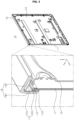
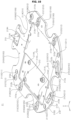
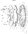
- FIGS. 1 to 22 illustrate examples of a display device according to embodiments of the present disclosure.
- a display device 1 may include a head 10.
- the head 10 may display images.
- the head 10 may be referred to as a display 10 or a display unit 10.
- the head 10 may include a first long side LS1, a second long side LS2 opposite to the first long side LS1, a first short side SS1 adjacent to the first long side LS1 and the second long side LS2, and a second short side SS2 opposite to the first short side SS1.
- first and second long sides LS1 and LS2 are longer than the first and second short sides SS1 and SS2, but it is also possible that lengths of the first and second long sides LS1 and LS2 may be approximately equal to lengths of the first and second short sides SS1 and SS2.
- a direction parallel to the short sides SS1 and SS2 of the head 10 may be referred to as a first direction DR1 or an up-down direction.
- a direction parallel to the long sides LS1 and LS2 of the head 10 may be referred to as a second direction DR2 or a left-right direction.
- a direction perpendicular to the long sides LS1 and LS2 and the short sides SS1 and SS2 of the head 10 may be referred to as a third direction DR3 or a front-rear direction.
- a side on which the head 10 displays an image may be referred to as a front side F, z, and a side opposite thereto may be referred to as a rear side R.
- the first short side SS1 may be referred to as a left side Le, x, and the second short side SS2 may be referred to as a right side Ri.
- the first long side LS1 may be referred to as an upper side U, y, and the second ling side LS2 may be referred to as a lower side D.
- the first long side LS1, the second long side LS2, the first short side SS1, and the second short side SS2 may be referred to as edges of the head 10.
- a position where the first long side LS1 and the first short side SS1 meet each other may be referred to as a first corner C1.
- a position where the first short side SS1 and the second long side LS2 meet each other may be referred to as a second corner C2.
- a position where the second long side LS2 and the second short side SS2 meet each other may be referred to as a third corner C3.
- a position where the second short side SS2 and the first long side LS1 meet each other may be referred to as a fourth corner C4.
- the display device 1 may include a base 20, a pole 30, and a motion module MM.
- the base 20 may have a substantially flat cylindrical shape.
- the base 20 may be placed on the ground.
- the pole 30 may extend vertically. A lower end of the pole 30 may be coupled to the base 20. The pole 30 may be adjacent to a rim of the base 20.
- the head 10 may be supported by the motion module MM, the pole 30, and the base 20, and may be spaced above the ground.
- the base 20, the pole 30, and the motion module MM may be collectively referred to as a stand.
- the motion module MM may be omitted, in which case the head 10 may be coupled to the pole 30.
- a battery Bt may be placed in the base 20, the pole 30, the motion module MM, and/or the head 10, and may be charged by an external power source.
- the display device 1, disconnected from the external power source, may be driven by the power of the battery Bt.
- the head 10 may include a display panel 11, a guide panel 12, a frame 13, an end frame 14, and a back cover 15.
- the display panel 11 may form a front surface of the head 10.
- the display panel 11 may be an OLED panel, an LCD panel, or an LED panel.
- the display panel 11 may divide an image into a plurality of pixels and may output the image while controlling color, brightness, and chroma of the respective pixels.
- the display panel 11 may be divided into an active area, in which the image is displayed, and a de-active area in which the image is not displayed.
- the display panel 11 may generate light corresponding to red, green, or blue color in response to a control signal.
- the guide panel 12 may extend along a periphery of the display panel 11.
- the guide panel may cover a side surface of the display panel 11.
- the frame 13 may be disposed at the rear of the display panel 11.
- Electronic components such as a Printed Circuit Board (PCB) may be coupled to a rear surface of the frame 13.
- PCB Printed Circuit Board
- a power supply board, a main board, a timing controller board, and a speaker may be mounted on a rear surface of the frame 13.
- the end frame 14 may extend along the guide panel 12.
- the end frame 14 may cover a side surface of the end frame 14, and may form a periphery of the head 10.
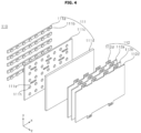
- a backlight unit 110; 110' may be mounted to the frame 13 (see FIG. 3 ) and may provide light to the display panel 11 (see FIG. 3 ).
- the display panel 11 may be referred to as an LCD panel.
- the backlight unit 110; 110' may include an optical layer 111 and an optical sheet 112.
- the optical layer 111 may include a substrate 111a, light sources 111b, a reflective sheet 111c, and a diffusion plate 111d (see FIG. 4 ).
- the substrate 111a may be coupled to a front surface of the frame 13 (see FIG. 3 ).
- the substrate 111a may have a plate shape or may be in the form of a plurality of bars which are spaced apart from each other.
- the light sources 111b may be mounted on the substrate 111a and may be light emitting diodes (LEDs).
- the reflective sheet 111c may cover the substrate 111a, and may have holes 111h in which the light sources 111b are disposed.
- the diffusion plate 111d may be spaced forward from the reflective sheet 111c.
- a spacer Ills may be disposed on a front surface of the reflective sheet 111c and may support a rear surface of the diffusion plate 111d.
- an optical layer 111' may include a substrate 111a', light sources 111b', a light guide plate 111e, and a reflective sheet 111f (see FIG. 5 ).
- the substrate 111a' may be disposed adjacent to one side of the light guide plate 111e and may extend along the one side.
- the light sources 111b' may be mounted on the substrate 111a' and may be light emitting diodes (LEDs).
- the reflective sheet 111f may be disposed at the rear of the light guide plate 111e.
- the optical sheet 112 may be disposed at the front of the diffusion plate 111d or the light guide plate 111e.
- the optical sheet 112 may include a plurality of sheets 112a, 112b, and 112c. Light may be provided to the display panel 11 (see FIG. 3 ) through the optical sheet 112.
- the display panel 11 according to the present disclosure may be an OLED panel that does not require the above backlight unit 110; 110' or may be another type of panel.
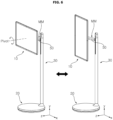
- a user may pivot the motion module MM relative to the head 10.
- a pivot axis may pass through the center of the head 10 and may be orthogonal to the head 10.
- the head 10 may be positioned in a horizontal mode.
- the head 10 may be positioned in a vertical mode.
- a user may tilt the head 10 relative to the motion module MM.
- a tilt axis is located behind the center of the head 10, and may be a horizontal axis parallel to the head 10.
- the user may swivel the head 10 relative to the motion module MM, and a swivel axis may be a vertical axis adjacent to a front end of the motion module MM.
- the user may swivel the head 10 relative to the motion module MM, and a swivel axis may be a vertical axis adjacent to a rear end of the motion module MM.
- the user may raise or lower the head 10 along the pole 30.
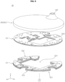
- the base 20 may include a first weight 21, a second weight 22, a third weight 23, a case 20C, and a wheel assembly 26.
- the first weight 21 may have a substantially circular plate shape with a plurality grooves or holes formed therein.
- the first weight 21 may include a metal material.
- the first weight 21 may be a steel plate.
- the first weight 21 may be hot rolled galvanized iron (HGI).
- the first weight 21 may be referred to as a lower weight 21, a bottom weight 21, a first weight plate 21, a first plate 21, a first layer 21, a first sheet 21, or a first member 21.
- the second weight 22 may be placed on the first weight 21.
- the second weight 22 may have a substantially open ring shape with a plurality of grooves formed therein.
- the second weight 22 may include a metal material.
- the second weight 22 may be a steel plate.
- the second weight 22 may be hot rolled galvanized iron (HGI).
- the second weight 22 may be referred to as a middle weight 22, a central weight 22, a second weight plate 22, a second plate 22, a second layer 22, a second sheet 22, or a second member 22.
- the third weight 23 may be placed on the second weight 22.
- the third weight 23 may have a substantially circular plate shape with a plurality of grooves or holes formed therein.
- the third weight 23 may include a metal material.
- the third weight 23 may be a steel plate.
- the third weight 23 may be hot rolled galvanized iron (HGI).
- the third weight 23 may be referred to as an upper weight 23, a top weight 23, a third weight plate 23, a third plate 23, a third layer 23, a third sheet 23, or a third member 23.
- the first to third weights 21, 22, and 23 may have the same thickness or different thicknesses.
- the first to third weights 21, 22, and 23 may have the same material and thickness, in which case the first to third weights 21, 22, and 23 may be manufactured with one type of base member.
- the bottom case 24 may have a round tray shape with an open top.
- the bottom case 24 may form the bottom of the case 20C.
- the first to third weights 21, 22, and 23 may be stacked on the bottom case 24.
- the bottom case 24 may be referred to as a lower case 24 or a first case 24.
- the top case 25 may have a round tray shape with an open bottom.
- the top case 25 may form the top of the case 20C.
- the top case 25 may cover the first to third weights 21, 22, and 23 stacked on the bottom case 24.
- the top case 25 may be referred to as an upper case 25 or the second case 25.
- the wheel assembly 25 may be disposed under the case 20C, and may be mounted to the case 20C.
- the wheel assembly 26 may allow the bottom case 24 to be spaced above the ground. That is, the base 20 may be moved via the wheel assembly 26 placed on the ground.
- the wheel assembly 26 may be referred to as a caster 26 or a moving caster 26.
- the first weight 21 may include a body 210, a fixing portion 211, a coupling portion 212, and a recessed portion 213.
- the body 210 may have a ring shape.
- the body 210 may include a flat portion 210F, and a side portion 210S bent downward from an edge of the flat portion 210F to form an edge of the body 210.
- Grooves 210G may be formed in the edge of the body 210.
- a first groove 210G1, a second groove 210G2, a third groove 210G3, a fourth groove 210G4, and a fifth groove 210G5 may be formed from an outer surface of the body 210 to the inside of the body 210, and may be spaced apart from each other in a circumferential direction of the body 210.
- the grooves 210G may be arc-shaped grooves.
- the grooves 210G may be grooves in the form of an arc (i.e., major arc) greater than a semicircle or semicircular grooves.
- the fixing portion 211 may be formed on a lower surface of the body 210.
- the fixing portion 211 may be formed by being pressed downward from an upper surface of the body 210, and may protrude from a lower surface of the body 210.
- Fixing portions 211 may be spaced apart from each other in a circumferential direction of the body 210.
- a first fixing portion 21111 may be disposed between the first groove 210G1 and the second groove 210G2.
- a second fixing portion 2112 may be disposed between the second groove 210G2 and the third groove 210G3.
- a third fixing portion 2113 may be disposed between the third groove 210G3 and the fourth groove 210G4.
- a fourth fixing portion 2114 may be disposed between the fifth groove 210G5 and the first groove 210G1.
- the first to fourth fixing portions 210G1, 210G2, 210G3, and 210G4 may be placed at the vertices of a square.
- the coupling portion 212 may be formed on the upper surface of the body 210.
- the coupling portion 212 may be formed by being pressed upward from the lower surface of the body 210, and may protrude from the upper surface of the body 210.
- Coupling portions 212 may be spaced apart from each other in the circumferential direction of the body 210.
- the first groove 210G1 may be disposed between a first coupling portion 2121 and a second coupling portion 2122.
- the second groove 210G2 may be disposed between a third coupling portion 2123 and a fourth coupling portion 2124.
- the third groove 210G3 may be disposed between a fifth coupling portion 2125 and a sixth coupling portion 2126.
- the fourth groove 210G4 and the fifth groove 210G5 may be disposed between a seventh coupling portion 2127 and an eighth coupling portion 2128.
- the recessed portion 213 may be disposed at a portion of the hole 210H formed at the center of the body 210 having a ring shape.
- the recessed portion 213 may have a rectangular plate shape, and the hole 210H of the body 210 which is located next to the recessed portion 213 may be a rectangular hole.
- the recessed portion 213 may be formed by being pressed downward from the upper surface of the body 210.
- a protruding portion 214 may protrude from an upper surface of the recessed portion 213.
- the protruding portion 214 may be formed by being pressed upward from the lower surface of the recessed portion 213.
- Protruding portions 214 may be spaced apart from each other. For example, first to fourth protruding portions 2141, 2142, 2143, and 2144 may be placed at the vertices of a square.
- the first weight 21 may be composed of one sheet or two or more sheets.
- a plurality of first weights 21 may have the same thickness and shape.
- the number of first weights 21 may be variable. If a relatively small number of first weights 21 are formed to a specific total thickness, manageability is facilitated. If a relatively large number of first weights 21 are formed to the specific total thickness, the specific total thickness may be easily adjusted within a relatively small range by adjusting the number of first weights 21. Further, if a relatively large number of first weights 21 are formed to the specific total thickness, vibration absorption is facilitated.
- the substrate BC may be mounted on the protruding portions 214.
- Fastening members Fa such as screws, may pass through the substrate BC to be fastened to holes of the protruding portions 214.
- At least some of the protruding portions 214 may include guide protrusions (not numbered) inserted into the substrate BC.
- the substrate BC may be a Printed Circuit Board (PCB) and may be referred to as a battery charger (BC).
- a bottom connector 27 may be seated on a seating portion of the first weight 21.
- the seating portion 215 may be formed by being recessed from an upper surface of the body 210.
- the bottom connector 27 may include a body 270, a cup 271, and a core 272.
- the bottom connector 27 may be referred to as a lower connector 27 or a first connector 27.
- a block 28 may be opposite to the seating portion 215 of the first weight 21 with respect to the bottom connector 27.
- the block 28 may be formed by die casting including a material such as aluminum (Al).
- the block 28 may include a body 280, a wall 281, and a mount 282.
- the body 280 may cover the body 270 of the bottom connector 27, and the cup 271 of the bottom connector 27 may pass through the body 280.
- a fastening member Fb such as a screw, may pass through the body 280 to be fastened to the body 270, thereby allowing the bottom connector 27 to be coupled to the block 28.
- a first groove 280a may be formed on the left side of the body 280 and may have a curvature corresponding to the fifth groove 210G5.
- a second groove 280b may be formed on the right side of the body 280 and may have a curvature corresponding to the fourth groove 210G4.
- the wall 281 may protrude upward from an upper surface of the body 280, and may extend along the arc.
- the wall 280 may surround at least a portion of a side surface of the cup 271 passing through the body 280.
- the mount 282 may be a recessed portion formed in an upper surface of the body 280.
- An indicator 29 may be disposed on the mount 282 of the block 28.
- a fastening member Fc such as a screw, may pass through the indicator 29 to be fastened to the mount 282, thereby allowing the indicator 29 to be coupled to the block 28.
- a bottom case 24 may include a bottom portion 241, a side portion 242, a recessed portion 243, and a storage portion 244.
- the bottom portion 241 may have a circular plate shape.
- the side portion 242 may be bent upward from a rim of the bottom portion 241 and may extend in a circumferential direction of the bottom portion 241.
- the recessed portion 243 may include a first part 143a having a hollow cylinder shape protruding upward from an upper surface of the bottom portion 241, a second part 243b formed at an upper end of the first part 243a, and a hole 243c formed in the second part 243b.
- the recessed portion 243 may be formed by being pressed upward from a lower surface of the bottom portion 241.
- a plurality of recessed portions 243 may be adjacent to the side portion 242 and may be spaced apart from each other along the side portion 242.
- the storage portion 244 may be formed by being pressed upward from the lower surface of the bottom portion 241, and may include an opening 244h facing the substrate BC.
- the first weight 21 may be positioned on the bottom portion 241 of the bottom case 24.
- the first groove 210G1 may surround a portion of a side surface of a first recessed portion 2431.
- the second groove 210G2 may surround a portion of a side surface of a second recessed portion 2432.
- the third groove 210G3 may surround a portion of a side surface of a third recessed portion 2433.
- the fourth groove 210G4 may surround a portion of a side surface of a fourth recessed portion 2434.
- the fifth groove 210G5 may surround a portion of a side surface of a fifth recessed portion 2435.
- the storage portion 244 may be disposed in the hole 210H of the first weight 21.
- a plurality of ribs 242r may be formed on an inner surface of the side portion 242 of the bottom case 24, and may be spaced apart from each other along the side portion 242. The plurality of ribs 242r may be adjacent to or in contact with the side surface of the first weight 21.
- Fastening members Fd such as screws, may pass through the bottom portion 241 of the bottom case 24 to be fastened to the fixing portions 211 of the first weight 21, thereby allowing the first weight 21 to be coupled to the bottom case 24.
- the battery Bt (see FIG. 8 ) may be inserted into the storage portion 244 from the bottom of the bottom case 24, and may be mounted on the first weight 21 through a fastening member Fy (see FIG. 17 ) such as a screw.
- a battery cover 24c my be coupled to the bottom portion 241 of the bottom case 24 by a fastening member Fyy such as a screw, and may cover a lower surface of the battery Bt.
- the battery cover 24c may form a lower surface of the base 20.
- the second weight 22 may be positioned on the first weight 21 positioned on the bottom case 24, and the third weight 23 may be positioned on the first weight 21.
- the second weight 22 may extend along the side portion 242 of the bottom case 24.
- the second weight 22 may have an open ring shape.
- the block 28 may be disposed between both ends of the second weight 22 that are spaced apart from each other.
- the second weight 22 may not cover the substrate BC, mounted on the first weight 21, and the storage portion 244 of the battery Bt that passes through the first weight 21. That is, the substrate BC and the storage portion 244 may be aligned with or disposed in a hole 22H of the second weight 22.
- the plurality of ribs 242r may be adjacent to or in contact with the side surface of the second weight 22.
- Grooves 22G may be formed in the edge of the second weight 22.
- the grooves 22G may be arc-shaped grooves.
- a first groove 22G1 may be formed from an outer surface of the second weight 22 to the inside of the second weight 22, and may surround a portion of the side surface of the first recessed portion 2431.
- a second groove 22G2 may be formed from an outer surface of the second weight 22 to the inside of the second weight 22, and may surround a portion of the side surface of the second recessed portion 2432.
- a third groove 22G3 may be formed from an outer surface of the second weight 22 to the inside of the second weight 22, and may surround a portion of the side surface of the third recessed portion 2433.
- a fourth groove 22G4 may be formed from an outer surface of the second weight 22 to the inside of the second weight 22, and may surround a portion of the side surface of the fourth recessed portion 2434.
- a fifth groove 22G5 may be formed from an outer surface of the second weight 22 to the inside of the second weight 22, and may surround a portion of the side surface of the fifth recessed portion 2435.
- the second weight 22 may include a plurality of parts 221, 222, and 223.
- the second weight 22 may be formed as one body without being divided into several parts.
- a first part 221 may be disposed on the left side of the storage portion 244, and the first groove 22G1 and the fifth groove 22G5 may be formed in the first part 221.
- the second part 222 may be disposed on the right side of the substrate BC, and the third groove 22G3 and the fourth groove 22G4 may be formed in the second part 222.
- the third part 223 may be disposed between the first part 221 and the second part 222, and may be opposite to the block 28.
- the plurality of parts 221, 222, and 223 may include a protrusion 22P or a groove 22Q engaged with each other.
- the second weight 22 may be composed of one sheet or two or more sheets.
- the plurality of second weights 22 may have the same thickness and shape.
- the number of second weights 22 may be variable. If a relatively small number of second weights 22 are formed to a specific total thickness, manageability is facilitated. If a relatively large number of second weights 22 are formed to the specific total thickness, the specific total thickness may be easily adjusted within a relatively small range by adjusting the number of second weights 22. Further, if a relatively large number of second weights 22 are formed to the specific total thickness, vibration absorption is facilitated.
- the third weight 23 may have a circular plate shape having a diameter smaller than a diameter of the side portion 242 of the bottom case 24.
- the third weight 23 may cover the second weight 22 (see FIG. 15 ) and the substrate BC (see FIG. 15 ), and the storage portion 244 of the battery Bt may be disposed in a hole 23H of the third weight 23. Accordingly, the third weight 23 may protect the substrate BC.
- the third weight 23 may cover a plurality of recessed portions 243 (see FIG. 15 ). The third weight 23 may be positioned on or adjacent to the recessed portions 243 (see FIG. 15 ).
- the third weight 23 may be composed of one sheet or two or more sheets.
- a plurality of third weights 23 may have the same thickness and shape.
- the number of third weights 23 may be variable. If a relatively small number of third weights 23 are formed to a specific total thickness, manageability is facilitated. If a relatively large number of third weights 23 are formed to the specific total thickness, the specific total thickness may be easily adjusted within a relatively small range by adjusting the number of third weights 23. Further, if a relatively large number of third weights 23 are formed to the specific total thickness, vibration absorption is facilitated.
- a coupling portion 212 of the first weight 212 may include a first hole 212a and a guide pin 212b.
- the first hole 212a may be formed through the coupling portion 212.
- a screw thread may be formed on an inner surface of the first hole 212a.
- the guide pin 212b may protrude upward from the coupling portion 212 and may have a pin shape.
- Each of the plurality of coupling portions 212 may have the first hole 212a. At least some of the plurality of coupling portions 212 may include the guide pin 212b. Each of the first to sixth coupling portions 2121, 2122, 2123, 2124, 2125, and 2126 may include the first hole 212a and the guide pin 212b. Each of the seventh and eighth coupling portions 2127 and 2128 may include the first hole 212a.
- the second weights 22 and the third weights 23 may be stacked on the coupling portion 212 of the first weight 21.
- the third weights 23a and 23b may be composed of two sheets.
- the second weights 22a, 22b, 22c, and 22d may be composed of four sheets (see FIG. 17 ).
- the second weights 22a, 22b, 22c, and 22d may be composed of six sheets (see FIG. 18 ).
- a second hole 220h may be formed through the second weights 22 and may be aligned with the first hole 212a of the coupling portion 212 of the first weight 21.
- Each of the plurality of second holes 220h may be aligned with the first hole 212a of each of the plurality of coupling portions 2121, 2122, 2123, 2124, 2125, 2126, 2127, and 2128.
- a third hole 230h may be formed through the third weights 23 and may be aligned with the second hole 220h of the second weight 22.
- Each of the plurality of third holes 230h may be aligned with each of the plurality of second holes 220h.
- Fastening members Ff such as screws, may pass through the third holes 230h and the second holes 220h to be fastened to the first holes 212a, thereby allowing the second weights 22 and the third weights 23 to be coupled to the first weight 21. Accordingly, the stability of the base 20 increases, thereby preventing the base 20 placed on the ground from being easily inverted. Further, driving stability of the moving base 20 may be improved, and vibration thereof may be reduced.
- specifications, such as weight and the like, of the base 20 may be variably adjusted by adjusting the number of second weights 22 and/or third weights 23 as needed.
- the first weight 21, the respective second weights 22, and the respective third weights 23 may all have the thickness of 2 mm.
- a total weight of the second weights 22 composed of six sheets may be greater than a weight of the first weight 21 and a total weight of the three weights 23 composed of two sheets.
- the weight of the block 28 may be smaller than the weight of the first weight 21.
- the guide pin 212b of the coupling portion 212 may pass through the second weights 22 and the third weights 23 which are positioned on the coupling portion 212. Accordingly, the guide pins 212b may guide coupling of the first to third weights 21, 22, and 23.
- the first weight 21 or the second weight 22 may be omitted.
- the first weight 21 may be omitted, and the second weights 22 and the third weights 23, which are stacked on top of each other, may be coupled to the bottom case 24.
- the second weights 22 may be omitted, and the third weight 23 spaced apart from the first weight 21 may be coupled to the first weight 21 and the bottom case 24 by a fastening member such as a screw.
- the second weights 22 may be omitted, and the third weight 23 contacting the first weight 21 while covering the recessed portions 243 may be coupled to the first weight 21 and the bottom case 24 by a fastening member such as a screw.
- a portion of the third weight 23 may protrude toward the first weight 21.
- the first weight 21 and the second weights 22 may be omitted, and the third weight 23 contacting or spaced apart from the bottom case 24 while covering the recessed portions 243 may be coupled to the bottom case 24 by a fastening member such as a screw.
- the body 26c may be opposite to the wheel plate 26a with respect to the stem 26b.
- a first portion 26ca of the body 26c may surround a portion of the stem 26b.
- a second portion 26cb and a third portion 26cc of the body 26c may protrude downward from the first portion 26ca and may be horizontally spaced apart from each other (see FIG. 17 ).
- the ball 26d may be disposed between a groove (not numbered) at a lower end of the stem 26b and a groove (not numbered) formed in an inner surface of the first portion 26ca.
- the body 26c may swivel around a longitudinal axis A1 of the stem 26b.
- the wheel 26f may be disposed between the second and third portions 26cb and 26cc of the body 26c and may surround an outer circumferential surface of the shaft 26e.
- the wheel 26f may protrude downward from a lower surface of the bottom case 24 (see distance Dw).
- the wheel 26f may include rubber, silicon, resin, or ABS material.
- the wheel 26f may rotate around the shaft 26e.
- the wheel 26f may rotate around the stem 26b. That is, the wheel 26f may rotate around two axes.
- the center of the shaft 26e may be offset a predetermined distance e from the longitudinal axis A1 of the stem 26b.
- the wheel assembly 26 is coupled to the third weight 23 with ensured flatness, such that driving stability may be improved, and the base 20 may smoothly move on the ground using the wheel assembly 26.
- a plurality of wheel assemblies 261, 262, 263, 264, and 265 may be spaced apart from each other along a circumference of the base 20.
- a portion of a first wheel assembly 261 may be inserted into the first recessed portion 2431 and may be coupled to the third weight 23 (see FIG. 16 ) by the fastening members Fe.
- a portion of a second wheel assembly 262 may be inserted into the second recessed portion 2432 and may be coupled to the third weight 23 (see FIG. 16 ) by the fastening members Fe.
- a portion of a third wheel assembly 263 may be inserted into the third recessed portion 2433 and may be coupled to the third weight 23 (see FIG. 16 ) by the fastening members Fe.
- first wheel assembly 261 and the second wheel assembly 262 may be adjacent to a bottom hole 20h.
- an angle theta a between the first wheel assembly 261 and the second wheel assembly 262 may be a minimum angle among angles between a plurality of wheel assemblies 291, 292, 293, 294, and 295.
- the top case 25 may cover the third weight 23 and may include a top portion 251 and a side portion 252.
- the top portion 251 may have a circular plate shape.
- the side portion 252 may be bent downward from a circumference of the top portion 251 and may extend in a circumferential direction of the top portion 251.
- the side portion 252 of the top case 25 may be coupled to the side portion 242 of the bottom case 24 by a snap-fit structure or a latch structure, and the like.
- a port 25P may be formed in an upper surface of the base 20 and may be adjacent to a circumference of the base 20.
- the portion 25P may be in the shape of a monticule.
- a guide rib 25 Pr may be formed on an inner surface of the port 25P.
- the wall 281 of the block 28 may be aligned with the port 25P.
- a guide rib 281r may be formed on an inner surface of the wall 281 and may be vertically aligned with the guide rib 25Pr.
- An insertion portion 31 may form a lower end of the pole 30.
- a diameter of the insertion portion 31 may be smaller than another portion of the pole 30.
- a guide slit 31s may be formed through a side surface of the insertion portion 31.
- Fastening members Fi such as screws, may pass through the bottom holes 20h formed in a lower surface of the base 20, the holes 215h (see FIG. 19 ) formed in the seating portion 215, and the body 280 (see FIG. 19 ) of the block 28, to be fastened to protruding portions 30a, 30b, 30c, and 30d of the pole 30, thereby allowing the pole 30 to be coupled to the base 20.
- the protruding portions 30a, 30b, 30c, and 30d may be formed on an inner surface of the pole 30, and may be spaced apart from each other in a circumferential direction of the top connector 79.
- the protruding portions 30a, 30b, 30c, and 30d may be referred to as ribs 30a, 30b, 30c, and 30d.
- the top connector 79 may be mounted inside the insertion portion 31.
- the top connector 79 may be referred to as an upper connector 79 or a second connector 79.
- the top connector 79 may be vertically aligned with the core 272 of the bottom connector 27.
- the top connector 79 may include a plurality of pins 79P
- the bottom connector 27 may include a plurality of pin holes 272h into which the plurality of pins 79P are inserted.
- the pin holes 272h may be formed in the core 272.
- the top connector 79 may include a plurality of pin holes
- the bottom connector 27 may include a plurality of pins inserted into the plurality of pin holes.
- the top connector 79 and the bottom connector 27 may be electrically connected to each other.
- a cable C connected to the top connector 79 may be electrically connected to the head 10 through the pole 30 and the motion module MM.
- the battery Bt placed in the storage portion 244 may be electrically connected to the substrate BC by a cable C11, and the substrate BC may be electrically connected to the bottom connector 27 by a cable C10. Accordingly, power of the battery Bt may be supplied to the head 10 through the cable C11, the substrate BC, the cable C10, the bottom connector 27, the top connector 79, and the cable C.
- An external power source may charge the battery Bt through a power cable connected to a jack 27i.
- a display device may include: a display panel; and a stand supporting the display panel, wherein the stand may include: a base; and a pole connecting the base and the display panel, wherein the base may include: a case; a weight positioned in an internal space of the case; a recessed portion recessed toward the internal space of the case from a bottom of the case, the recessed portion covered by the weight and having a hole facing the weight; and a wheel assembly inserted into the recessed portion, and protruding downward from the bottom of the case, wherein the wheel assembly may include a wheel plate positioned at the hole of the recessed portion and coupled to the weight.
- the case may include: a bottom case forming the bottom of the case and at which the recessed portion is formed; and a top case covering the weight and coupled to the bottom case, wherein the weight may include: a first weight positioned on the bottom case; a second weight positioned on the first weight; and a third weight positioned on the second weight and covering the recessed portion.
- the second weight may include a plurality of second weights which are stacked on top of each other.
- the third weight may include: a third lower weight covering the recessed portion; and a third upper weight positioned on the third lower weight, wherein the display device may further include a fastening member passing through the wheel plate and the third lower weight to be fastened to the third upper weight.
- the display device may further include a fastening member fixing the second and third weights to the first weight
- the first weight may include: a body fixed to the bottom case; and a coupling portion on which the second weight is positioned, the coupling portion protruding from the body toward the second weight and having a first hole to which the fastening member is coupled, wherein: the second weight may include a second hole through which the fastening member passes, the second hole aligned with the first hole; and the third weight may include a third hole through which the fastening member passes, the third hole aligned with the second hole.
- the coupling portion may further include a guide pin protruding from the coupling portion and passing through the second and third weights.
- the display device may further include a substrate mounted on the first weight, wherein the second weight may further include a hole aligned with the substrate, and the third weight may cover the substrate.
- the display device may further include a battery electrically connected to the substrate, wherein the first to third weights may include holes at which the battery is positioned.
- the second weight may include a plurality of parts adjacent to each other in a perimeter direction of the bottom case.
- the display device may further include: a substrate mounted in the base and electrically connected to the bottom connector; and a battery mounted in the base and electrically connected to the substrate.
- the stand may further include an arm connecting the pole and the display panel and extending in a direction intersecting the pole.
- a structure for freely moving a display device may be provided.
Landscapes
- Engineering & Computer Science (AREA)
- General Engineering & Computer Science (AREA)
- Mechanical Engineering (AREA)
- Microelectronics & Electronic Packaging (AREA)
- Physics & Mathematics (AREA)
- General Physics & Mathematics (AREA)
- Theoretical Computer Science (AREA)
- Devices For Indicating Variable Information By Combining Individual Elements (AREA)
Abstract
Description
- This application claims priority to
Korean Patent Application No. 10-2023-0194047, filed on December 28, 2023 - The present disclosure relates to a display device.
- With the development of the information society, there have been growing demands for various types of display devices, and in order to meet these demands, various display devices, such as a liquid crystal display (LCD), a plasma display panel (PDP), an electroluminescent display (ELD), a vacuum fluorescent display (VFD), an organic light emitting diode (OLED), etc., have been studied and used recently.
- Among these devices, the LCD panel includes a TFT substrate and a color substrate which are positioned opposite each other with a liquid crystal layer interposed therebetween, and displays images by using light provided by a backlight unit. Further, the OLED panel may display images by using a self-emitting organic layer deposited on a substrate on which transparent electrodes are formed.
- Recently, many studies are being conducted on a structure for freely moving a display device.
- It is an objective of the present disclosure to solve the above and other problems.
- Another object of the present disclosure may be to provide a display device including a stand for a display panel.
- Another object of the present disclosure may be to provide a structure for freely moving a display device.
- Another object of the present disclosure may be to provide a structure for improving standing stability and moving stability of a display device.
- Another object of the present disclosure may be to provide a structure for reducing vibration of a moving display device.
- Another object of the present disclosure may be to provide a structure for electrically connecting a base and a pole of a display device.
- In accordance with an aspect of the present disclosure for achieving the above and other objectives, a display device may include: a display panel; and a stand supporting the display panel, wherein the stand may include: a base; and a pole connecting the base and the display panel, wherein the base may include: a case; a weight positioned in an internal space of the case; a recessed portion recessed toward the internal space of the case from a bottom of the case, the recessed portion covered by the weight and having a hole facing the weight; and a wheel assembly inserted into the recessed portion, and protruding downward from the bottom of the case, wherein the wheel assembly may include a wheel plate positioned at the hole of the recessed portion and coupled to the weight.
- The above and other objects, features and advantages of the present disclosure will be more apparent from the following detailed description in conjunction with the accompanying drawings, in which:
FIGS. 1 to 22 illustrate examples of a display device according to embodiments of the present disclosure. - Hereinafter, the present disclosure will be described in detail with reference to the accompanying drawings, in which the same reference numerals are used throughout the drawings to designate the same or similar components, and a redundant description thereof will be omitted.
- The suffixes, such as "module" and "unit," for elements used in the following description are given simply in view of the ease of the description, and do not have a distinguishing meaning or role.
- In addition, it will be noted that a detailed description of known arts will be omitted if it is determined that the detailed description of the known arts can obscure the embodiments of the present disclosure. Further, the accompanying drawings are used to help easily understand various technical features and it should be understood that the embodiments presented herein are not limited by the accompanying drawings. As such, the present disclosure should be construed to extend to any alterations, equivalents and substitutes in addition to those which are particularly set out in the accompanying drawings.
- It will be understood that although the terms, "first," "second," etc., may be used herein to describe various elements, these elements should not be limited by these terms. These terms are only used to distinguish one element from another.
- It will be understood that when an element is referred to as being "connected" or "coupled" to another element, it can be directly connected or coupled to the other element or intervening elements may be present. In contrast, when an element is referred to as being "directly connected" or "directly coupled" to another element, there are no intervening elements present.
- A singular representation may include a plural representation unless context clearly indicates otherwise.
- It should be understood that the terms, "comprise," "include," "have," etc. when used in this specification, specify the presence of stated features, integers, steps, operations, elements, components, or combinations thereof but do not preclude the presence or addition of one or more other features, integers, steps, operations, elements, components, or combinations thereof.
- References to directions, such as up (U), down (D), left (Le), right (Ri), front (F), and rear (R), shown in the drawings are provided merely for convenience of explanation and are not intended for limiting the scope of the present disclosure.
- Referring to
FIGS. 1 and2 , adisplay device 1 may include ahead 10. Thehead 10 may display images. Thehead 10 may be referred to as adisplay 10 or adisplay unit 10. - The
head 10 may include a first long side LS1, a second long side LS2 opposite to the first long side LS1, a first short side SS1 adjacent to the first long side LS1 and the second long side LS2, and a second short side SS2 opposite to the first short side SS1. For convenience of explanation, it is illustrated and described that the first and second long sides LS1 and LS2 are longer than the first and second short sides SS1 and SS2, but it is also possible that lengths of the first and second long sides LS1 and LS2 may be approximately equal to lengths of the first and second short sides SS1 and SS2. - A direction parallel to the short sides SS1 and SS2 of the
head 10 may be referred to as a first direction DR1 or an up-down direction. A direction parallel to the long sides LS1 and LS2 of thehead 10 may be referred to as a second direction DR2 or a left-right direction. A direction perpendicular to the long sides LS1 and LS2 and the short sides SS1 and SS2 of thehead 10 may be referred to as a third direction DR3 or a front-rear direction. - A side on which the
head 10 displays an image may be referred to as a front side F, z, and a side opposite thereto may be referred to as a rear side R. The first short side SS1 may be referred to as a left side Le, x, and the second short side SS2 may be referred to as a right side Ri. The first long side LS1 may be referred to as an upper side U, y, and the second ling side LS2 may be referred to as a lower side D. - The first long side LS1, the second long side LS2, the first short side SS1, and the second short side SS2 may be referred to as edges of the
head 10. A position where the first long side LS1 and the first short side SS1 meet each other may be referred to as a first corner C1. A position where the first short side SS1 and the second long side LS2 meet each other may be referred to as a second corner C2. A position where the second long side LS2 and the second short side SS2 meet each other may be referred to as a third corner C3. A position where the second short side SS2 and the first long side LS1 meet each other may be referred to as a fourth corner C4. - The
display device 1 may include abase 20, apole 30, and a motion module MM. - The
base 20 may have a substantially flat cylindrical shape. Thebase 20 may be placed on the ground. - The
pole 30 may extend vertically. A lower end of thepole 30 may be coupled to thebase 20. Thepole 30 may be adjacent to a rim of thebase 20. - The motion module MM may extend in a direction intersecting the
pole 30. A first side of the motion module MM may be adjacent to the upper end of thepole 30 and may be coupled to thepole 30. A second side of the motion module MM may be coupled to thehead 10. The motion module MM may include afront connector 40, anarm 50, and arear connector 60. Thefront connector 40 may be disposed at the rear of thehead 10 and coupled to thehead 10, and may be an articulated connector. Therear connector 60 may be disposed at the front of thepole 30 and coupled to thepole 30, and may be an articulated connector. Thearm 50 may connect thefront connector 40 and therear connector 60, and may be rotatably coupled to thefront connector 40 and therear connector 60. That is, both sides of the motion module MM may rotate relative to the rotatinghead 10 or thepole 30. Alternatively, at least one of the both sides of the motion module MM may be fixed to thehead 10 or thepole 30. - Accordingly, the
head 10 may be supported by the motion module MM, thepole 30, and thebase 20, and may be spaced above the ground. Thebase 20, thepole 30, and the motion module MM may be collectively referred to as a stand. Alternatively, the motion module MM may be omitted, in which case thehead 10 may be coupled to thepole 30. - A battery Bt may be placed in the
base 20, thepole 30, the motion module MM, and/or thehead 10, and may be charged by an external power source. Thedisplay device 1, disconnected from the external power source, may be driven by the power of the battery Bt. - Referring to
FIGS. 2 and3 , thehead 10 may include a display panel 11, a guide panel 12, aframe 13, anend frame 14, and aback cover 15. - The display panel 11 may form a front surface of the
head 10. For example, the display panel 11 may be an OLED panel, an LCD panel, or an LED panel. The display panel 11 may divide an image into a plurality of pixels and may output the image while controlling color, brightness, and chroma of the respective pixels. The display panel 11 may be divided into an active area, in which the image is displayed, and a de-active area in which the image is not displayed. The display panel 11 may generate light corresponding to red, green, or blue color in response to a control signal. - The guide panel 12 may extend along a periphery of the display panel 11. The guide panel may cover a side surface of the display panel 11.
- The
frame 13 may be disposed at the rear of the display panel 11. Electronic components, such as a Printed Circuit Board (PCB), may be coupled to a rear surface of theframe 13. For example, a power supply board, a main board, a timing controller board, and a speaker may be mounted on a rear surface of theframe 13. - The
end frame 14 may extend along the guide panel 12. Theend frame 14 may cover a side surface of theend frame 14, and may form a periphery of thehead 10. - The
back cover 15 may be disposed at the rear of theframe 13. Theback cover 15 may cover theframe 13 and may form a rear surface of thehead 10. - Referring to
FIGS. 4 and5 , abacklight unit 110; 110' may be mounted to the frame 13 (seeFIG. 3 ) and may provide light to the display panel 11 (seeFIG. 3 ). In this case, the display panel 11 may be referred to as an LCD panel. Thebacklight unit 110; 110' may include anoptical layer 111 and anoptical sheet 112. - The
optical layer 111 may include asubstrate 111a,light sources 111b, areflective sheet 111c, and adiffusion plate 111d (seeFIG. 4 ). Thesubstrate 111a may be coupled to a front surface of the frame 13 (seeFIG. 3 ). Thesubstrate 111a may have a plate shape or may be in the form of a plurality of bars which are spaced apart from each other. Thelight sources 111b may be mounted on thesubstrate 111a and may be light emitting diodes (LEDs). Thereflective sheet 111c may cover thesubstrate 111a, and may haveholes 111h in which thelight sources 111b are disposed. Thediffusion plate 111d may be spaced forward from thereflective sheet 111c. A spacer Ills may be disposed on a front surface of thereflective sheet 111c and may support a rear surface of thediffusion plate 111d. - Alternatively, an optical layer 111' may include a
substrate 111a',light sources 111b', alight guide plate 111e, and areflective sheet 111f (seeFIG. 5 ). Thesubstrate 111a' may be disposed adjacent to one side of thelight guide plate 111e and may extend along the one side. Thelight sources 111b' may be mounted on thesubstrate 111a' and may be light emitting diodes (LEDs). Thereflective sheet 111f may be disposed at the rear of thelight guide plate 111e. - The
optical sheet 112 may be disposed at the front of thediffusion plate 111d or thelight guide plate 111e. Theoptical sheet 112 may include a plurality ofsheets FIG. 3 ) through theoptical sheet 112. - The display panel 11 according to the present disclosure may be an OLED panel that does not require the
above backlight unit 110; 110' or may be another type of panel. - Referring to
FIG. 6 , a user may pivot the motion module MM relative to thehead 10. A pivot axis may pass through the center of thehead 10 and may be orthogonal to thehead 10. Referring to the left drawing ofFIG. 6 , thehead 10 may be positioned in a horizontal mode. Referring to the right drawing ofFIG. 6 , thehead 10 may be positioned in a vertical mode. - Referring to
FIG. 7 , a user may tilt thehead 10 relative to the motion module MM. A tilt axis is located behind the center of thehead 10, and may be a horizontal axis parallel to thehead 10. The user may swivel thehead 10 relative to the motion module MM, and a swivel axis may be a vertical axis adjacent to a front end of the motion module MM. The user may swivel thehead 10 relative to the motion module MM, and a swivel axis may be a vertical axis adjacent to a rear end of the motion module MM. The user may raise or lower thehead 10 along thepole 30. - Referring to
FIGS. 8 and9 , thebase 20 may include afirst weight 21, asecond weight 22, athird weight 23, acase 20C, and awheel assembly 26. - The
first weight 21 may have a substantially circular plate shape with a plurality grooves or holes formed therein. Thefirst weight 21 may include a metal material. Thefirst weight 21 may be a steel plate. Thefirst weight 21 may be hot rolled galvanized iron (HGI). Thefirst weight 21 may be referred to as alower weight 21, abottom weight 21, afirst weight plate 21, afirst plate 21, afirst layer 21, afirst sheet 21, or afirst member 21. - The
second weight 22 may be placed on thefirst weight 21. Thesecond weight 22 may have a substantially open ring shape with a plurality of grooves formed therein. Thesecond weight 22 may include a metal material. Thesecond weight 22 may be a steel plate. Thesecond weight 22 may be hot rolled galvanized iron (HGI). Thesecond weight 22 may be referred to as amiddle weight 22, acentral weight 22, asecond weight plate 22, asecond plate 22, asecond layer 22, asecond sheet 22, or asecond member 22. - The
third weight 23 may be placed on thesecond weight 22. Thethird weight 23 may have a substantially circular plate shape with a plurality of grooves or holes formed therein. Thethird weight 23 may include a metal material. Thethird weight 23 may be a steel plate. Thethird weight 23 may be hot rolled galvanized iron (HGI). Thethird weight 23 may be referred to as anupper weight 23, atop weight 23, athird weight plate 23, athird plate 23, athird layer 23, athird sheet 23, or athird member 23. - The first to
third weights third weights third weights - The
case 20C may form the exterior of thebase 20, and may cover the first tothird weights case 20C may have a substantially flat circular box shape. Thecase 20C may be referred to as abody 20C, ahousing 20C, or anouter cover 20C. Thecase 20C may include abottom case 24 and atop case 25. - The
bottom case 24 may have a round tray shape with an open top. Thebottom case 24 may form the bottom of thecase 20C. The first tothird weights bottom case 24. Thebottom case 24 may be referred to as alower case 24 or afirst case 24. - The
top case 25 may have a round tray shape with an open bottom. Thetop case 25 may form the top of thecase 20C. Thetop case 25 may cover the first tothird weights bottom case 24. Thetop case 25 may be referred to as anupper case 25 or thesecond case 25. - The
wheel assembly 25 may be disposed under thecase 20C, and may be mounted to thecase 20C. Thewheel assembly 26 may allow thebottom case 24 to be spaced above the ground. That is, thebase 20 may be moved via thewheel assembly 26 placed on the ground. Thewheel assembly 26 may be referred to as acaster 26 or a movingcaster 26. - Referring to
FIGS. 10 and11 , thefirst weight 21 may include abody 210, a fixingportion 211, acoupling portion 212, and a recessedportion 213. - The
body 210 may have a ring shape. Thebody 210 may include aflat portion 210F, and aside portion 210S bent downward from an edge of theflat portion 210F to form an edge of thebody 210.Grooves 210G may be formed in the edge of thebody 210. A first groove 210G1, a second groove 210G2, a third groove 210G3, a fourth groove 210G4, and a fifth groove 210G5 may be formed from an outer surface of thebody 210 to the inside of thebody 210, and may be spaced apart from each other in a circumferential direction of thebody 210. Thegrooves 210G may be arc-shaped grooves. For example, thegrooves 210G may be grooves in the form of an arc (i.e., major arc) greater than a semicircle or semicircular grooves. - Cut-
outs 210C may be formed by cutting out a portion of thebody 210. A first cut-out 210C1 may be formed by cutting out a first portion of thebody 210, and the first groove 210G1 may be formed from the first cut-out 210C1 to the inside of thebody 210. A second cut-out 210C2 may be formed by cutting out a second portion of thebody 210, and the second groove 210G2 may be formed from the second cut-out 210C2 to the inside of thebody 210. A third cut-out 210C3 may be formed by cutting out a third portion of thebody 210, and the third groove 210G3 may be formed from the third cut-out 210C3 to the inside of thebody 210. - The fixing
portion 211 may be formed on a lower surface of thebody 210. The fixingportion 211 may be formed by being pressed downward from an upper surface of thebody 210, and may protrude from a lower surface of thebody 210. Fixingportions 211 may be spaced apart from each other in a circumferential direction of thebody 210. A first fixing portion 21111 may be disposed between the first groove 210G1 and the second groove 210G2. Asecond fixing portion 2112 may be disposed between the second groove 210G2 and the third groove 210G3. Athird fixing portion 2113 may be disposed between the third groove 210G3 and the fourth groove 210G4. Afourth fixing portion 2114 may be disposed between the fifth groove 210G5 and the first groove 210G1. The first to fourth fixing portions 210G1, 210G2, 210G3, and 210G4 may be placed at the vertices of a square. - The
coupling portion 212 may be formed on the upper surface of thebody 210. Thecoupling portion 212 may be formed by being pressed upward from the lower surface of thebody 210, and may protrude from the upper surface of thebody 210. Couplingportions 212 may be spaced apart from each other in the circumferential direction of thebody 210. The first groove 210G1 may be disposed between afirst coupling portion 2121 and asecond coupling portion 2122. The second groove 210G2 may be disposed between athird coupling portion 2123 and afourth coupling portion 2124. The third groove 210G3 may be disposed between afifth coupling portion 2125 and asixth coupling portion 2126. The fourth groove 210G4 and the fifth groove 210G5 may be disposed between aseventh coupling portion 2127 and aneighth coupling portion 2128. - The recessed
portion 213 may be disposed at a portion of thehole 210H formed at the center of thebody 210 having a ring shape. The recessedportion 213 may have a rectangular plate shape, and thehole 210H of thebody 210 which is located next to the recessedportion 213 may be a rectangular hole. The recessedportion 213 may be formed by being pressed downward from the upper surface of thebody 210. A protrudingportion 214 may protrude from an upper surface of the recessedportion 213. The protrudingportion 214 may be formed by being pressed upward from the lower surface of the recessedportion 213. Protrudingportions 214 may be spaced apart from each other. For example, first to fourth protrudingportions - The
first weight 21 may be composed of one sheet or two or more sheets. A plurality offirst weights 21 may have the same thickness and shape. The number offirst weights 21 may be variable. If a relatively small number offirst weights 21 are formed to a specific total thickness, manageability is facilitated. If a relatively large number offirst weights 21 are formed to the specific total thickness, the specific total thickness may be easily adjusted within a relatively small range by adjusting the number offirst weights 21. Further, if a relatively large number offirst weights 21 are formed to the specific total thickness, vibration absorption is facilitated. - The substrate BC may be mounted on the protruding
portions 214. Fastening members Fa, such as screws, may pass through the substrate BC to be fastened to holes of the protrudingportions 214. At least some of the protrudingportions 214 may include guide protrusions (not numbered) inserted into the substrate BC. The substrate BC may be a Printed Circuit Board (PCB) and may be referred to as a battery charger (BC). - A
bottom connector 27 may be seated on a seating portion of thefirst weight 21. Theseating portion 215 may be formed by being recessed from an upper surface of thebody 210. Thebottom connector 27 may include abody 270, acup 271, and acore 272. Thebottom connector 27 may be referred to as alower connector 27 or afirst connector 27. - A
block 28 may be opposite to theseating portion 215 of thefirst weight 21 with respect to thebottom connector 27. For example, theblock 28 may be formed by die casting including a material such as aluminum (Al). Theblock 28 may include abody 280, awall 281, and amount 282. Thebody 280 may cover thebody 270 of thebottom connector 27, and thecup 271 of thebottom connector 27 may pass through thebody 280. A fastening member Fb, such as a screw, may pass through thebody 280 to be fastened to thebody 270, thereby allowing thebottom connector 27 to be coupled to theblock 28. Afirst groove 280a may be formed on the left side of thebody 280 and may have a curvature corresponding to the fifth groove 210G5. Asecond groove 280b may be formed on the right side of thebody 280 and may have a curvature corresponding to the fourth groove 210G4. Thewall 281 may protrude upward from an upper surface of thebody 280, and may extend along the arc. Thewall 280 may surround at least a portion of a side surface of thecup 271 passing through thebody 280. Themount 282 may be a recessed portion formed in an upper surface of thebody 280. - An
indicator 29 may be disposed on themount 282 of theblock 28. A fastening member Fc, such as a screw, may pass through theindicator 29 to be fastened to themount 282, thereby allowing theindicator 29 to be coupled to theblock 28. - Referring to
FIGS. 12 and13 , abottom case 24 may include abottom portion 241, aside portion 242, a recessedportion 243, and astorage portion 244. Thebottom portion 241 may have a circular plate shape. Theside portion 242 may be bent upward from a rim of thebottom portion 241 and may extend in a circumferential direction of thebottom portion 241. The recessedportion 243 may include a first part 143a having a hollow cylinder shape protruding upward from an upper surface of thebottom portion 241, asecond part 243b formed at an upper end of thefirst part 243a, and ahole 243c formed in thesecond part 243b. The recessedportion 243 may be formed by being pressed upward from a lower surface of thebottom portion 241. A plurality of recessedportions 243 may be adjacent to theside portion 242 and may be spaced apart from each other along theside portion 242. Thestorage portion 244 may be formed by being pressed upward from the lower surface of thebottom portion 241, and may include anopening 244h facing the substrate BC. - The
first weight 21 may be positioned on thebottom portion 241 of thebottom case 24. The first groove 210G1 may surround a portion of a side surface of a first recessedportion 2431. The second groove 210G2 may surround a portion of a side surface of a second recessedportion 2432. The third groove 210G3 may surround a portion of a side surface of a third recessedportion 2433. The fourth groove 210G4 may surround a portion of a side surface of a fourth recessedportion 2434. The fifth groove 210G5 may surround a portion of a side surface of a fifth recessedportion 2435. Thestorage portion 244 may be disposed in thehole 210H of thefirst weight 21. - A plurality of
ribs 242r may be formed on an inner surface of theside portion 242 of thebottom case 24, and may be spaced apart from each other along theside portion 242. The plurality ofribs 242r may be adjacent to or in contact with the side surface of thefirst weight 21. - Fastening members Fd, such as screws, may pass through the
bottom portion 241 of thebottom case 24 to be fastened to the fixingportions 211 of thefirst weight 21, thereby allowing thefirst weight 21 to be coupled to thebottom case 24. - The battery Bt (see
FIG. 8 ) may be inserted into thestorage portion 244 from the bottom of thebottom case 24, and may be mounted on thefirst weight 21 through a fastening member Fy (seeFIG. 17 ) such as a screw. Abattery cover 24c my be coupled to thebottom portion 241 of thebottom case 24 by a fastening member Fyy such as a screw, and may cover a lower surface of the battery Bt. Thebattery cover 24c may form a lower surface of thebase 20. - Referring to
FIG. 14 , thesecond weight 22 may be positioned on thefirst weight 21 positioned on thebottom case 24, and thethird weight 23 may be positioned on thefirst weight 21. - Referring to
FIG. 15 , thesecond weight 22 may extend along theside portion 242 of thebottom case 24. For example, thesecond weight 22 may have an open ring shape. Theblock 28 may be disposed between both ends of thesecond weight 22 that are spaced apart from each other. Thesecond weight 22 may not cover the substrate BC, mounted on thefirst weight 21, and thestorage portion 244 of the battery Bt that passes through thefirst weight 21. That is, the substrate BC and thestorage portion 244 may be aligned with or disposed in ahole 22H of thesecond weight 22. The plurality ofribs 242r may be adjacent to or in contact with the side surface of thesecond weight 22. -
Grooves 22G may be formed in the edge of thesecond weight 22. Thegrooves 22G may be arc-shaped grooves. A first groove 22G1 may be formed from an outer surface of thesecond weight 22 to the inside of thesecond weight 22, and may surround a portion of the side surface of the first recessedportion 2431. A second groove 22G2 may be formed from an outer surface of thesecond weight 22 to the inside of thesecond weight 22, and may surround a portion of the side surface of the second recessedportion 2432. A third groove 22G3 may be formed from an outer surface of thesecond weight 22 to the inside of thesecond weight 22, and may surround a portion of the side surface of the third recessedportion 2433. A fourth groove 22G4 may be formed from an outer surface of thesecond weight 22 to the inside of thesecond weight 22, and may surround a portion of the side surface of the fourth recessedportion 2434. A fifth groove 22G5 may be formed from an outer surface of thesecond weight 22 to the inside of thesecond weight 22, and may surround a portion of the side surface of the fifth recessedportion 2435. - The
second weight 22 may include a plurality ofparts second weight 22 may be formed as one body without being divided into several parts. For example, afirst part 221 may be disposed on the left side of thestorage portion 244, and the first groove 22G1 and the fifth groove 22G5 may be formed in thefirst part 221. For example, thesecond part 222 may be disposed on the right side of the substrate BC, and the third groove 22G3 and the fourth groove 22G4 may be formed in thesecond part 222. For example, thethird part 223 may be disposed between thefirst part 221 and thesecond part 222, and may be opposite to theblock 28. The plurality ofparts protrusion 22P or agroove 22Q engaged with each other. - The
second weight 22 may be composed of one sheet or two or more sheets. The plurality ofsecond weights 22 may have the same thickness and shape. The number ofsecond weights 22 may be variable. If a relatively small number ofsecond weights 22 are formed to a specific total thickness, manageability is facilitated. If a relatively large number ofsecond weights 22 are formed to the specific total thickness, the specific total thickness may be easily adjusted within a relatively small range by adjusting the number ofsecond weights 22. Further, if a relatively large number ofsecond weights 22 are formed to the specific total thickness, vibration absorption is facilitated. - Referring to
FIG. 16 , thethird weight 23 may have a circular plate shape having a diameter smaller than a diameter of theside portion 242 of thebottom case 24. Thethird weight 23 may cover the second weight 22 (seeFIG. 15 ) and the substrate BC (seeFIG. 15 ), and thestorage portion 244 of the battery Bt may be disposed in ahole 23H of thethird weight 23. Accordingly, thethird weight 23 may protect the substrate BC. In addition, thethird weight 23 may cover a plurality of recessed portions 243 (seeFIG. 15 ). Thethird weight 23 may be positioned on or adjacent to the recessed portions 243 (seeFIG. 15 ). - The
third weight 23 may be composed of one sheet or two or more sheets. A plurality ofthird weights 23 may have the same thickness and shape. The number ofthird weights 23 may be variable. If a relatively small number ofthird weights 23 are formed to a specific total thickness, manageability is facilitated. If a relatively large number ofthird weights 23 are formed to the specific total thickness, the specific total thickness may be easily adjusted within a relatively small range by adjusting the number ofthird weights 23. Further, if a relatively large number ofthird weights 23 are formed to the specific total thickness, vibration absorption is facilitated. - Referring back to
FIG. 10 , acoupling portion 212 of thefirst weight 212 may include afirst hole 212a and aguide pin 212b. Thefirst hole 212a may be formed through thecoupling portion 212. A screw thread may be formed on an inner surface of thefirst hole 212a. Theguide pin 212b may protrude upward from thecoupling portion 212 and may have a pin shape. - Each of the plurality of
coupling portions 212 may have thefirst hole 212a. At least some of the plurality ofcoupling portions 212 may include theguide pin 212b. Each of the first tosixth coupling portions first hole 212a and theguide pin 212b. Each of the seventh andeighth coupling portions first hole 212a. - Referring to
FIGS. 17 and18 , thesecond weights 22 and thethird weights 23 may be stacked on thecoupling portion 212 of thefirst weight 21. For example, thethird weights second weights FIG. 17 ). In another example, thesecond weights FIG. 18 ). - A
second hole 220h may be formed through thesecond weights 22 and may be aligned with thefirst hole 212a of thecoupling portion 212 of thefirst weight 21. Each of the plurality ofsecond holes 220h may be aligned with thefirst hole 212a of each of the plurality ofcoupling portions - A
third hole 230h may be formed through thethird weights 23 and may be aligned with thesecond hole 220h of thesecond weight 22. Each of the plurality ofthird holes 230h may be aligned with each of the plurality ofsecond holes 220h. - Fastening members Ff, such as screws, may pass through the
third holes 230h and thesecond holes 220h to be fastened to thefirst holes 212a, thereby allowing thesecond weights 22 and thethird weights 23 to be coupled to thefirst weight 21. Accordingly, the stability of the base 20 increases, thereby preventing the base 20 placed on the ground from being easily inverted. Further, driving stability of the movingbase 20 may be improved, and vibration thereof may be reduced. In addition, specifications, such as weight and the like, of the base 20 may be variably adjusted by adjusting the number ofsecond weights 22 and/orthird weights 23 as needed. For example, thefirst weight 21, the respectivesecond weights 22, and the respectivethird weights 23 may all have the thickness of 2 mm. For example, a total weight of thesecond weights 22 composed of six sheets may be greater than a weight of thefirst weight 21 and a total weight of the threeweights 23 composed of two sheets. For example, the weight of theblock 28 may be smaller than the weight of thefirst weight 21. - The
guide pin 212b of thecoupling portion 212 may pass through thesecond weights 22 and thethird weights 23 which are positioned on thecoupling portion 212. Accordingly, the guide pins 212b may guide coupling of the first tothird weights - Alternatively, at least one of the
first weight 21 or thesecond weight 22 may be omitted. Thefirst weight 21 may be omitted, and thesecond weights 22 and thethird weights 23, which are stacked on top of each other, may be coupled to thebottom case 24. Thesecond weights 22 may be omitted, and thethird weight 23 spaced apart from thefirst weight 21 may be coupled to thefirst weight 21 and thebottom case 24 by a fastening member such as a screw. Thesecond weights 22 may be omitted, and thethird weight 23 contacting thefirst weight 21 while covering the recessedportions 243 may be coupled to thefirst weight 21 and thebottom case 24 by a fastening member such as a screw. To this end, a portion of thethird weight 23 may protrude toward thefirst weight 21. Thefirst weight 21 and thesecond weights 22 may be omitted, and thethird weight 23 contacting or spaced apart from thebottom case 24 while covering the recessedportions 243 may be coupled to thebottom case 24 by a fastening member such as a screw. - An
upper hole 231h may be formed through thethird weights 23, and alower hole 221h may be formed through thesecond weights 22. Theupper hole 231h and thelower hole 221h may be aligned with each other, and a diameter of theupper hole 231h may be greater than a diameter of thelower hole 221h. A fastening member (not shown), such as a screw, may pass through theupper hole 231h to be fastened to thelower hole 221h, and the head of a screw may be inserted into theupper hole 231h, thereby allowing thesecond weights 22 to be tied together. - Referring to
FIGS. 19 and16 , thebody 280 of theblock 28 may be seated on thefirst weight 21, and thebody 270 of thebottom connector 27 may be sandwiched between thebody 280 and theseating portion 215 of thefirst weight 21. Thethird weight 23 may cover thebody 280 of theblock 28, and may have a groove 23Ga through which thewall 281 of theblock 28 passes. Theindicator 29 mounted on thebody 280 of theblock 28 may be exposed upward through a hole 23Gb of thethird weight 23. - First fastening members Fg, such as screws, may pass through the
first weight 21 to be fastened to thebody 280 of theblock 28. Second fastening members Fh, such as screws, may pass through thethird weight 23 to be fastened to thebody 280 of theblock 28. Accordingly, thebody 280 of theblock 28 may be sandwiched between thefirst weight 21 and thethird weight 23, and thebottom connector 27 may be firmly mounted to theweights block 28. - Referring to
FIG. 20 , awheel assembly 26 may include awheel plate 26a, astem 26b, abody 26c, aball 26d, ashaft 26e, awheel 26f, and abearing 26g. - The
wheel plate 26a may have a generally rectangular plate shape (seeFIG. 15 ). Thewheel plate 26a may be disposed in thehole 243c of the recessedportion 243. Holes 26ah may be adjacent to the edge of thewheel plate 26a and may be formed through thewheel plate 26a. Thethird weight 23 may cover the recessedportion 243 and thewheel plate 26a, and holes 232h (seeFIGS. 16 and17 ) of thethird weight 23 may be aligned with the holes 26ah of thewheel plate 26a. For example, thethird weight 23 may be composed of two sheets, and the hole 232h may be formed through a thirdlower weight 23a and a thirdupper weight 23b. In this case, the thirdupper weight 23b may include a protrudingportion 23P having the hole 232h, and a screw thread may be formed on an inner surface of the hole 232h formed in the protrudingportion 23P. The protrudingportion 23P may be referred to as a tappingportion 23P. Fastening members Fe, such as screws, may pass through the holes 26ah to be fastened to the hole 232h, thereby allowing thewheel plate 26a to be coupled to thethird weight 23. - The
stem 26b may be disposed in an internal space of thefirst part 243a, and may protrude downward from thewheel plate 26a. Thestem 26b may be elongated vertically. A first portion 26ba of thestem 26b may be disposed below thewheel plate 26a, and a second portion 26bb of thestem 26b may be fixed in the form of a rivet to a recessed portion 26ag formed in an upper surface of thewheel plate 26a. - The
body 26c may be opposite to thewheel plate 26a with respect to thestem 26b. A first portion 26ca of thebody 26c may surround a portion of thestem 26b. A second portion 26cb and a third portion 26cc of thebody 26c may protrude downward from the first portion 26ca and may be horizontally spaced apart from each other (seeFIG. 17 ). - The
ball 26d may be disposed between a groove (not numbered) at a lower end of thestem 26b and a groove (not numbered) formed in an inner surface of the first portion 26ca. Thebody 26c may swivel around a longitudinal axis A1 of thestem 26b. - The
shaft 26e may be elongated horizontally and may be coupled to the second and third portions 26cb and 26cc of thebody 26c. - The
wheel 26f may be disposed between the second and third portions 26cb and 26cc of thebody 26c and may surround an outer circumferential surface of theshaft 26e. Thewheel 26f may protrude downward from a lower surface of the bottom case 24 (see distance Dw). Thewheel 26f may include rubber, silicon, resin, or ABS material. - The
bearing 26g may be disposed between theshaft 26e and thewheel 26f and may be coupled to theshaft 26e and thewheel 26f. Thebearing 26g may include an inner ring 26ga, an outer ring 26gb, and rotating members 26gc. The inner ring 26ga may be coupled to an outer circumference of theshaft 26e. The outer ring 26gb may be concentric with the inner ring 26ga and may have a greater diameter than the inner ring 26ga. The rotating members 26gc may be rotatably coupled between the inner ring 26ga and the outer ring 26gb. The rotating members 26gc may be balls or rollers. Thebearing 26g may support rotation of thewheel 26f about theshaft 26e. - Accordingly, the
wheel 26f may rotate around theshaft 26e. In addition, thewheel 26f may rotate around thestem 26b. That is, thewheel 26f may rotate around two axes. The center of theshaft 26e may be offset a predetermined distance e from the longitudinal axis A1 of thestem 26b. Thewheel assembly 26 is coupled to thethird weight 23 with ensured flatness, such that driving stability may be improved, and the base 20 may smoothly move on the ground using thewheel assembly 26. - A plurality of
wheel assemblies FIG. 13 ) may be spaced apart from each other along a circumference of thebase 20. A portion of afirst wheel assembly 261 may be inserted into the first recessedportion 2431 and may be coupled to the third weight 23 (seeFIG. 16 ) by the fastening members Fe. A portion of asecond wheel assembly 262 may be inserted into the second recessedportion 2432 and may be coupled to the third weight 23 (seeFIG. 16 ) by the fastening members Fe. A portion of athird wheel assembly 263 may be inserted into the third recessedportion 2433 and may be coupled to the third weight 23 (seeFIG. 16 ) by the fastening members Fe. A portion of afourth wheel assembly 264 may be inserted into the fourth recessedportion 2434 and may be coupled to the third weight 23 (seeFIG. 16 ) by the fastening members Fe. A portion of afifth wheel assembly 265 may be inserted into the fifth recessedportion 2435 and may be coupled to the third weight 23 (seeFIG. 16 ) by the fastening members Fe. - In this case, the
first wheel assembly 261 and thesecond wheel assembly 262 may be adjacent to abottom hole 20h. With respect to a center Oc of thebase 20, an angle theta a between thefirst wheel assembly 261 and thesecond wheel assembly 262 may be a minimum angle among angles between a plurality of wheel assemblies 291, 292, 293, 294, and 295. With respect to the center Oc of thebase 20, an angle theta b between thesecond wheel assembly 262 and thethird wheel assembly 263, an angle theta c between thethird wheel assembly 263 and thefourth wheel assembly 264, an angle theta d between thefourth wheel assembly 264 and thefifth wheel assembly 265, and an angle theta e between thefifth wheel assembly 265 and thefirst wheel assembly 261 each may be greater than the angle theta a. For example, the angles theta b, theta c, theta d, and theta e may be substantially equal to each other. - The
top case 25 may cover thethird weight 23 and may include atop portion 251 and aside portion 252. Thetop portion 251 may have a circular plate shape. Theside portion 252 may be bent downward from a circumference of thetop portion 251 and may extend in a circumferential direction of thetop portion 251. Theside portion 252 of thetop case 25 may be coupled to theside portion 242 of thebottom case 24 by a snap-fit structure or a latch structure, and the like. - Referring to
FIGS. 21 and22 , aport 25P may be formed in an upper surface of thebase 20 and may be adjacent to a circumference of thebase 20. Theportion 25P may be in the shape of a monticule. Aguide rib 25 Pr may be formed on an inner surface of theport 25P. - The
wall 281 of theblock 28 may be aligned with theport 25P. Aguide rib 281r may be formed on an inner surface of thewall 281 and may be vertically aligned with the guide rib 25Pr. - An
insertion portion 31 may form a lower end of thepole 30. A diameter of theinsertion portion 31 may be smaller than another portion of thepole 30. A guide slit 31s may be formed through a side surface of theinsertion portion 31. When theinsertion portion 31 is inserted into theport 25P and thewall 281, theguide ribs 26r and 281r may be inserted into the guide slit 31s. That is, theguide ribs 26r and 281r may guide coupling of thepole 30 and thebase 20. - Fastening members Fi, such as screws, may pass through the
bottom holes 20h formed in a lower surface of thebase 20, theholes 215h (seeFIG. 19 ) formed in theseating portion 215, and the body 280 (seeFIG. 19 ) of theblock 28, to be fastened to protrudingportions pole 30, thereby allowing thepole 30 to be coupled to thebase 20. The protrudingportions pole 30, and may be spaced apart from each other in a circumferential direction of thetop connector 79. The protrudingportions ribs - The
top connector 79 may be mounted inside theinsertion portion 31. Thetop connector 79 may be referred to as anupper connector 79 or asecond connector 79. Thetop connector 79 may be vertically aligned with thecore 272 of thebottom connector 27. - For example, the
top connector 79 may include a plurality ofpins 79P, and thebottom connector 27 may include a plurality of pin holes 272h into which the plurality ofpins 79P are inserted. The pin holes 272h may be formed in thecore 272. - In another example, the
top connector 79 may include a plurality of pin holes, and thebottom connector 27 may include a plurality of pins inserted into the plurality of pin holes. - Accordingly, when the
insertion portion 31 is inserted into thebase 20, thetop connector 79 and thebottom connector 27 may be electrically connected to each other. A cable C connected to thetop connector 79 may be electrically connected to thehead 10 through thepole 30 and the motion module MM. - The battery Bt placed in the
storage portion 244 may be electrically connected to the substrate BC by a cable C11, and the substrate BC may be electrically connected to thebottom connector 27 by a cable C10. Accordingly, power of the battery Bt may be supplied to thehead 10 through the cable C11, the substrate BC, the cable C10, thebottom connector 27, thetop connector 79, and the cable C. An external power source may charge the battery Bt through a power cable connected to ajack 27i. - The
indicator 29 may be electrically connected to the substrate BC through a cable C12, and may detect a remaining capacity of the battery Bt. A light emitting element IDL (seeFIG. 21 ) of theindicator 29 may be provided on an upper surface of thebase 20, and may display a remaining capacity of the battery Bt for a user. - Referring to
FIGS. 1 to 22 , a display device may include: a display panel; and a stand supporting the display panel, wherein the stand may include: a base; and a pole connecting the base and the display panel, wherein the base may include: a case; a weight positioned in an internal space of the case; a recessed portion recessed toward the internal space of the case from a bottom of the case, the recessed portion covered by the weight and having a hole facing the weight; and a wheel assembly inserted into the recessed portion, and protruding downward from the bottom of the case, wherein the wheel assembly may include a wheel plate positioned at the hole of the recessed portion and coupled to the weight. - The display device may further include a screw fixing the wheel plate to the weight.
- The case may include: a bottom case forming the bottom of the case and at which the recessed portion is formed; and a top case covering the weight and coupled to the bottom case, wherein the weight may include: a first weight positioned on the bottom case; a second weight positioned on the first weight; and a third weight positioned on the second weight and covering the recessed portion.
- The second weight may include a plurality of second weights which are stacked on top of each other.
- The third weight may include: a third lower weight covering the recessed portion; and a third upper weight positioned on the third lower weight, wherein the display device may further include a fastening member passing through the wheel plate and the third lower weight to be fastened to the third upper weight.
- The display device may further include a fastening member fixing the second and third weights to the first weight, wherein the first weight may include: a body fixed to the bottom case; and a coupling portion on which the second weight is positioned, the coupling portion protruding from the body toward the second weight and having a first hole to which the fastening member is coupled, wherein: the second weight may include a second hole through which the fastening member passes, the second hole aligned with the first hole; and the third weight may include a third hole through which the fastening member passes, the third hole aligned with the second hole.
- The coupling portion may further include a guide pin protruding from the coupling portion and passing through the second and third weights.
- The recessed portion may include a plurality of recessed portions which are adjacent to a perimeter of the bottom case and spaced apart from each other along the perimeter, wherein the wheel assembly may include a plurality of wheel assemblies inserted into the plurality of recessed portions, wherein: the first weight may include grooves in which the plurality of recessed portions are positioned, the grooves formed at a side surface of the first weight; the second weight may include grooves in which the plurality of recessed portions are positioned, the grooves formed at a side surface of the second weight; and the third weight may cover the plurality of recessed portions.
- The display device may further include a substrate mounted on the first weight, wherein the second weight may further include a hole aligned with the substrate, and the third weight may cover the substrate.
- The display device may further include a battery electrically connected to the substrate, wherein the first to third weights may include holes at which the battery is positioned.
- The second weight may include a plurality of parts adjacent to each other in a perimeter direction of the bottom case.
- The display device may further include: a head having the display panel; a top connector mounted in the pole and electrically connected to the head; and a bottom connector mounted in the base and electrically connected to the top connector, wherein the weight may include a pair of weights opposite to each other with respect to the bottom connector.
- The display device may further include a block to which the bottom connector is coupled, wherein the pair of weights may include: a lower weight on which the block is positioned, the lower weight coupled to the block; and an upper weight covering the block and coupled to the block, wherein the block and the bottom connector may be sandwiched between the lower weight and the upper weight.
- The display device may further include: a substrate mounted in the base and electrically connected to the bottom connector; and a battery mounted in the base and electrically connected to the substrate.
- The stand may further include an arm connecting the pole and the display panel and extending in a direction intersecting the pole.
- The display device according to the present disclosure has the following effects.
- According to at least one of the embodiments of the present disclosure, a display device including a stand for a display panel may be provided.
- According to at least one of the embodiments of the present disclosure, a structure for freely moving a display device may be provided.
- According to at least one of the embodiments of the present disclosure, a structure for improving standing stability and moving stability of a display device may be provided.
- According to at least one of the embodiments of the present disclosure, a structure for reducing vibration of a moving display device may be provided.
- According to at least one of the embodiments of the present disclosure, a structure for electrically connecting a base and a pole of a display device may be provided.
- Certain embodiments or other embodiments of the invention described above are not mutually exclusive or distinct from each other. Any or all elements of the embodiments of the invention described above may be combined or combined with each other in configuration or function.
- For example, a configuration "A" described in one embodiment of the invention and the drawings and a configuration "B" described in another embodiment of the invention and the drawings may be combined with each other. Namely, although the combination between the configurations is not directly described, the combination is possible except in the case where it is described that the combination is impossible.
- The foregoing embodiments are merely examples and are not to be considered as limiting the present disclosure. The scope of the present disclosure should be determined by rational interpretation of the appended claims, and all modifications within the equivalents of the disclosure are intended to be included within the scope of the present disclosure.
Claims (15)
- A display device (1) comprising:a display panel (10); anda stand supporting the display panel (10),wherein the stand comprises:a base (20); anda pole (30) connecting the base (20) and the display panel (10),wherein the base (20) comprises:a case (20C);a weight positioned in an internal space of the case (20C);a recessed portion (243) recessed toward the internal space of the case (20C) from a bottom of the case (20C), the recessed portion (243) covered by the weight and having a hole (243c) facing the weight; anda wheel assembly (26) inserted into the recessed portion, and protruding downward from the bottom of the case,wherein the wheel assembly (26) comprises a wheel plate (26a) positioned at the hole (243c) of the recessed portion (243) and coupled to the weight.
- The display device (1) of claim 1, further comprising a screw (Fe) fixing the wheel plate (26a) to the weight.
- The display device (1) of claim 1 or 2, wherein the case (20C) comprises:a bottom case (24) forming the bottom of the case (20C) and at which the recessed portion (243) is formed; anda top case (25) covering the weight and coupled to the bottom case (24),wherein the weight comprises:a first weight (21) positioned on the bottom case (24);a second weight (22) positioned on the first weight (21); anda third weight (23) positioned on the second weight (22) and covering the recessed portion (243).
- The display device (1) of claim 3, wherein the second weight (22) comprises a plurality of second weights (22) which are stacked on top of each other.
- The display device (1) of claim 3 or 4, wherein the third weight (23) comprises:a third lower weight (23a) covering the recessed portion (243); anda third upper weight (23b) positioned on the third lower weight (23a),wherein the display device (1) further comprises a fastening member (Fe) passing through the wheel plate (26a) and the third lower weight (23a) to be fastened to the third upper weight (23b).
- The display device (1) of any one of claims 3 to 5, further comprising a fastening member (Ff) fixing the second and third weights (22, 23) to the first weight (21),
wherein the first weight (21) comprises:a body (210) fixed to the bottom case (24); anda coupling portion (212) which protrudes from the body (210) toward the second weight (22), on which the second weight (22) is positioned, and which includes a first hole (212a) to which the fastening member (Ff) is coupled,wherein the second weight (22) comprises:a second hole (220h) which is aligned with the first hole (212a) and through which the fastening member (Ff) passes, andwherein the third weight (23) comprises:
a third hole (230h) which is aligned with the second hole (220h) and through which the fastening member (Ff) passes. - The display device (1) of claim 6, wherein the coupling portion (212) further comprises a guide pin (212b) protruding from the coupling portion (212) and passing through the second and third weights (22, 23).
- The display device (1) of any one of claims 3 to 7, wherein the recessed portion (243) comprises a plurality of recessed portions (243) which are adjacent to a perimeter of the bottom case (24) and spaced apart from each other along the perimeter,wherein the wheel assembly (26) comprises a plurality of wheel assemblies (26) inserted into the plurality of recessed portions (243),wherein:the first weight (21) comprises grooves (210G) which are formed at a lateral side of the first weight (21) and in which the plurality of recessed portions (243) are positioned;the second weight (22) comprises grooves (22G) which are formed at a lateral side of the second weight (22) and in which the plurality of recessed portions (243) are positioned; andthe third weight (23) covers the plurality of recessed portions (243).
- The display device (1) of any one of claims 3 to 8, further comprising a substrate (BC) mounted on the first weight (21),wherein the second weight (22) further comprises a hole (22H) aligned with the substrate (BC), andwherein the third weight (23) covers the substrate (BC).
- The display device (1) of claim 9, further comprising a battery (Bt) electrically connected to the substrate (BC),
wherein the first to third weights (21, 22, 23) comprise holes (210H, 22H, 23H) at which the battery (Bt) is positioned. - The display device (1) of any one of claims 3 to 10, wherein the second weight (22) comprises a plurality of parts (221, 222, 223) adjacent to each other in a perimeter direction of the bottom case (24).
- The display device (1) of any one of claims 1 to 11, further comprising:a head (10) having the display panel (11);a top connector (79) mounted in the pole (30) and electrically connected to the head (10); anda bottom connector (27) mounted in the base (20) and electrically connected to the top connector (79),wherein the weight comprises a pair of weights (21, 23) opposite to each other with respect to the bottom connector (27).
- The display device (1) of claim 12, further comprising a block (28) to which the bottom connector (27) is coupled,
wherein the pair of weights (21, 23) comprise:a lower weight (21) on which the block (28) is positioned and which is coupled to the block (28); andan upper weight (23) covering the block (28) and coupled to the block (28),wherein the block (28) and the bottom connector (27) are sandwiched between the lower weight (21) and the upper weight (23). - The display device (1) of claim 12 or 13, further comprising:a substrate (BC) mounted in the base (20) and electrically connected to the bottom connector (27); anda battery (Bt) mounted in the base (20) and electrically connected to the substrate (BC).
- The display device (1) of any one of claims 1 to 14, wherein the stand further comprises an arm (50) extending in a direction intersecting the pole (30) and connecting the pole (30) and the display panel (11).
Applications Claiming Priority (1)
| Application Number | Priority Date | Filing Date | Title |
|---|---|---|---|
| KR1020230194047A KR20250102423A (en) | 2023-12-28 | 2023-12-28 | Display device |
Publications (1)
| Publication Number | Publication Date |
|---|---|
| EP4579117A1 true EP4579117A1 (en) | 2025-07-02 |
Family
ID=91073156
Family Applications (1)
| Application Number | Title | Priority Date | Filing Date |
|---|---|---|---|
| EP24175093.4A Pending EP4579117A1 (en) | 2023-12-28 | 2024-05-10 | Display device |
Country Status (4)
| Country | Link |
|---|---|
| US (1) | US20250220834A1 (en) |
| EP (1) | EP4579117A1 (en) |
| KR (3) | KR20250102423A (en) |
| CN (1) | CN120231938A (en) |
Families Citing this family (1)
| Publication number | Priority date | Publication date | Assignee | Title |
|---|---|---|---|---|
| USD1123946S1 (en) * | 2024-12-27 | 2026-04-28 | Lg Electronics Inc. | Stand base for display device |
Citations (2)
| Publication number | Priority date | Publication date | Assignee | Title |
|---|---|---|---|---|
| US6305659B1 (en) * | 1999-02-07 | 2001-10-23 | Leica Microsystems Ag | Stand, in particular a microscope stand |
| US20050189005A1 (en) * | 2003-12-29 | 2005-09-01 | Smith James C. | Umbrella base |
Family Cites Families (2)
| Publication number | Priority date | Publication date | Assignee | Title |
|---|---|---|---|---|
| US6446930B1 (en) * | 1998-10-18 | 2002-09-10 | Hanamint Corporation, Inc. | Umbrella base |
| KR102320552B1 (en) * | 2019-09-16 | 2021-11-01 | 엘지전자 주식회사 | Display device |
-
2023
- 2023-12-28 KR KR1020230194047A patent/KR20250102423A/en active Pending
-
2024
- 2024-05-08 US US18/658,368 patent/US20250220834A1/en active Pending
- 2024-05-10 EP EP24175093.4A patent/EP4579117A1/en active Pending
- 2024-09-23 CN CN202411324251.5A patent/CN120231938A/en active Pending
-
2025
- 2025-11-14 KR KR1020250172505A patent/KR20250167540A/en active Pending
-
2026
- 2026-02-02 KR KR1020260020974A patent/KR20260033496A/en active Pending
Patent Citations (2)
| Publication number | Priority date | Publication date | Assignee | Title |
|---|---|---|---|---|
| US6305659B1 (en) * | 1999-02-07 | 2001-10-23 | Leica Microsystems Ag | Stand, in particular a microscope stand |
| US20050189005A1 (en) * | 2003-12-29 | 2005-09-01 | Smith James C. | Umbrella base |
Also Published As
| Publication number | Publication date |
|---|---|
| KR20260033496A (en) | 2026-03-10 |
| KR20250167540A (en) | 2025-12-01 |
| US20250220834A1 (en) | 2025-07-03 |
| KR20250102423A (en) | 2025-07-07 |
| CN120231938A (en) | 2025-07-01 |
Similar Documents
| Publication | Publication Date | Title |
|---|---|---|
| US12072733B2 (en) | Display device | |
| US8576551B2 (en) | Image display device | |
| KR20260033496A (en) | Display device | |
| US12222753B2 (en) | Display device | |
| KR102543892B1 (en) | Display device | |
| US12607292B2 (en) | Mobile terminal | |
| US12204368B2 (en) | Display device | |
| KR20250174883A (en) | Display device | |
| EP4418681A1 (en) | Speaker assembly and display device comprising same | |
| CN224050101U (en) | Display device | |
| EP4607080A1 (en) | Display device | |
| KR102958842B1 (en) | Display device | |
| KR20260003721A (en) | display device | |
| US20240069384A1 (en) | Backlight unit and display apparatus having the same | |
| KR20240087034A (en) | Display device |
Legal Events
| Date | Code | Title | Description |
|---|---|---|---|
| PUAI | Public reference made under article 153(3) epc to a published international application that has entered the european phase |
Free format text: ORIGINAL CODE: 0009012 |
|
| STAA | Information on the status of an ep patent application or granted ep patent |
Free format text: STATUS: REQUEST FOR EXAMINATION WAS MADE |
|
| 17P | Request for examination filed |
Effective date: 20240510 |
|
| AK | Designated contracting states |
Kind code of ref document: A1 Designated state(s): AL AT BE BG CH CY CZ DE DK EE ES FI FR GB GR HR HU IE IS IT LI LT LU LV MC ME MK MT NL NO PL PT RO RS SE SI SK SM TR |
|
| RIC1 | Information provided on ipc code assigned before grant |
Ipc: F16M 11/42 20060101AFI20260313BHEP Ipc: F16M 11/24 20060101ALI20260313BHEP Ipc: F16M 11/12 20060101ALI20260313BHEP |