EP4579116A1 - Display device - Google Patents
Display device Download PDFInfo
- Publication number
- EP4579116A1 EP4579116A1 EP22956619.5A EP22956619A EP4579116A1 EP 4579116 A1 EP4579116 A1 EP 4579116A1 EP 22956619 A EP22956619 A EP 22956619A EP 4579116 A1 EP4579116 A1 EP 4579116A1
- Authority
- EP
- European Patent Office
- Prior art keywords
- mount
- slider
- hole
- plate
- cover
- Prior art date
- Legal status (The legal status is an assumption and is not a legal conclusion. Google has not performed a legal analysis and makes no representation as to the accuracy of the status listed.)
- Pending
Links
Images














Classifications
-
- F—MECHANICAL ENGINEERING; LIGHTING; HEATING; WEAPONS; BLASTING
- F16—ENGINEERING ELEMENTS AND UNITS; GENERAL MEASURES FOR PRODUCING AND MAINTAINING EFFECTIVE FUNCTIONING OF MACHINES OR INSTALLATIONS; THERMAL INSULATION IN GENERAL
- F16M—FRAMES, CASINGS OR BEDS OF ENGINES, MACHINES OR APPARATUS, NOT SPECIFIC TO ENGINES, MACHINES OR APPARATUS PROVIDED FOR ELSEWHERE; STANDS; SUPPORTS
- F16M11/00—Stands or trestles as supports for apparatus or articles placed thereon ; Stands for scientific apparatus such as gravitational force meters
- F16M11/20—Undercarriages with or without wheels
- F16M11/22—Undercarriages with or without wheels with approximately constant height, e.g. with constant length of column or of legs
-
- F—MECHANICAL ENGINEERING; LIGHTING; HEATING; WEAPONS; BLASTING
- F16—ENGINEERING ELEMENTS AND UNITS; GENERAL MEASURES FOR PRODUCING AND MAINTAINING EFFECTIVE FUNCTIONING OF MACHINES OR INSTALLATIONS; THERMAL INSULATION IN GENERAL
- F16M—FRAMES, CASINGS OR BEDS OF ENGINES, MACHINES OR APPARATUS, NOT SPECIFIC TO ENGINES, MACHINES OR APPARATUS PROVIDED FOR ELSEWHERE; STANDS; SUPPORTS
- F16M11/00—Stands or trestles as supports for apparatus or articles placed thereon ; Stands for scientific apparatus such as gravitational force meters
- F16M11/02—Heads
- F16M11/04—Means for attachment of apparatus; Means allowing adjustment of the apparatus relatively to the stand
- F16M11/041—Allowing quick release of the apparatus
-
- F—MECHANICAL ENGINEERING; LIGHTING; HEATING; WEAPONS; BLASTING
- F16—ENGINEERING ELEMENTS AND UNITS; GENERAL MEASURES FOR PRODUCING AND MAINTAINING EFFECTIVE FUNCTIONING OF MACHINES OR INSTALLATIONS; THERMAL INSULATION IN GENERAL
- F16M—FRAMES, CASINGS OR BEDS OF ENGINES, MACHINES OR APPARATUS, NOT SPECIFIC TO ENGINES, MACHINES OR APPARATUS PROVIDED FOR ELSEWHERE; STANDS; SUPPORTS
- F16M11/00—Stands or trestles as supports for apparatus or articles placed thereon ; Stands for scientific apparatus such as gravitational force meters
- F16M11/02—Heads
- F16M11/04—Means for attachment of apparatus; Means allowing adjustment of the apparatus relatively to the stand
- F16M11/06—Means for attachment of apparatus; Means allowing adjustment of the apparatus relatively to the stand allowing pivoting
- F16M11/12—Means for attachment of apparatus; Means allowing adjustment of the apparatus relatively to the stand allowing pivoting in more than one direction
- F16M11/125—Means for attachment of apparatus; Means allowing adjustment of the apparatus relatively to the stand allowing pivoting in more than one direction for tilting and rolling
-
- F—MECHANICAL ENGINEERING; LIGHTING; HEATING; WEAPONS; BLASTING
- F16—ENGINEERING ELEMENTS AND UNITS; GENERAL MEASURES FOR PRODUCING AND MAINTAINING EFFECTIVE FUNCTIONING OF MACHINES OR INSTALLATIONS; THERMAL INSULATION IN GENERAL
- F16M—FRAMES, CASINGS OR BEDS OF ENGINES, MACHINES OR APPARATUS, NOT SPECIFIC TO ENGINES, MACHINES OR APPARATUS PROVIDED FOR ELSEWHERE; STANDS; SUPPORTS
- F16M11/00—Stands or trestles as supports for apparatus or articles placed thereon ; Stands for scientific apparatus such as gravitational force meters
- F16M11/02—Heads
- F16M11/04—Means for attachment of apparatus; Means allowing adjustment of the apparatus relatively to the stand
- F16M11/06—Means for attachment of apparatus; Means allowing adjustment of the apparatus relatively to the stand allowing pivoting
- F16M11/12—Means for attachment of apparatus; Means allowing adjustment of the apparatus relatively to the stand allowing pivoting in more than one direction
- F16M11/14—Means for attachment of apparatus; Means allowing adjustment of the apparatus relatively to the stand allowing pivoting in more than one direction with ball-joint
-
- F—MECHANICAL ENGINEERING; LIGHTING; HEATING; WEAPONS; BLASTING
- F16—ENGINEERING ELEMENTS AND UNITS; GENERAL MEASURES FOR PRODUCING AND MAINTAINING EFFECTIVE FUNCTIONING OF MACHINES OR INSTALLATIONS; THERMAL INSULATION IN GENERAL
- F16M—FRAMES, CASINGS OR BEDS OF ENGINES, MACHINES OR APPARATUS, NOT SPECIFIC TO ENGINES, MACHINES OR APPARATUS PROVIDED FOR ELSEWHERE; STANDS; SUPPORTS
- F16M11/00—Stands or trestles as supports for apparatus or articles placed thereon ; Stands for scientific apparatus such as gravitational force meters
- F16M11/20—Undercarriages with or without wheels
- F16M11/2007—Undercarriages with or without wheels comprising means allowing pivoting adjustment
- F16M11/2021—Undercarriages with or without wheels comprising means allowing pivoting adjustment around a horizontal axis
-
- F—MECHANICAL ENGINEERING; LIGHTING; HEATING; WEAPONS; BLASTING
- F16—ENGINEERING ELEMENTS AND UNITS; GENERAL MEASURES FOR PRODUCING AND MAINTAINING EFFECTIVE FUNCTIONING OF MACHINES OR INSTALLATIONS; THERMAL INSULATION IN GENERAL
- F16M—FRAMES, CASINGS OR BEDS OF ENGINES, MACHINES OR APPARATUS, NOT SPECIFIC TO ENGINES, MACHINES OR APPARATUS PROVIDED FOR ELSEWHERE; STANDS; SUPPORTS
- F16M11/00—Stands or trestles as supports for apparatus or articles placed thereon ; Stands for scientific apparatus such as gravitational force meters
- F16M11/20—Undercarriages with or without wheels
- F16M11/24—Undercarriages with or without wheels changeable in height or length of legs, also for transport only, e.g. by means of tubes screwed into each other
- F16M11/26—Undercarriages with or without wheels changeable in height or length of legs, also for transport only, e.g. by means of tubes screwed into each other by telescoping, with or without folding
- F16M11/28—Undercarriages for supports with one single telescoping pillar
-
- F—MECHANICAL ENGINEERING; LIGHTING; HEATING; WEAPONS; BLASTING
- F16—ENGINEERING ELEMENTS AND UNITS; GENERAL MEASURES FOR PRODUCING AND MAINTAINING EFFECTIVE FUNCTIONING OF MACHINES OR INSTALLATIONS; THERMAL INSULATION IN GENERAL
- F16M—FRAMES, CASINGS OR BEDS OF ENGINES, MACHINES OR APPARATUS, NOT SPECIFIC TO ENGINES, MACHINES OR APPARATUS PROVIDED FOR ELSEWHERE; STANDS; SUPPORTS
- F16M11/00—Stands or trestles as supports for apparatus or articles placed thereon ; Stands for scientific apparatus such as gravitational force meters
- F16M11/42—Stands or trestles as supports for apparatus or articles placed thereon ; Stands for scientific apparatus such as gravitational force meters with arrangement for propelling the support stands on wheels
-
- G—PHYSICS
- G02—OPTICS
- G02F—OPTICAL DEVICES OR ARRANGEMENTS FOR THE CONTROL OF LIGHT BY MODIFICATION OF THE OPTICAL PROPERTIES OF THE MEDIA OF THE ELEMENTS INVOLVED THEREIN; NON-LINEAR OPTICS; FREQUENCY-CHANGING OF LIGHT; OPTICAL LOGIC ELEMENTS; OPTICAL ANALOGUE/DIGITAL CONVERTERS
- G02F1/00—Devices or arrangements for the control of the intensity, colour, phase, polarisation or direction of light arriving from an independent light source, e.g. switching, gating or modulating; Non-linear optics
- G02F1/01—Devices or arrangements for the control of the intensity, colour, phase, polarisation or direction of light arriving from an independent light source, e.g. switching, gating or modulating; Non-linear optics for the control of the intensity, phase, polarisation or colour
- G02F1/13—Devices or arrangements for the control of the intensity, colour, phase, polarisation or direction of light arriving from an independent light source, e.g. switching, gating or modulating; Non-linear optics for the control of the intensity, phase, polarisation or colour based on liquid crystals, e.g. single liquid crystal display cells
- G02F1/133—Constructional arrangements; Operation of liquid crystal cells; Circuit arrangements
- G02F1/1333—Constructional arrangements; Manufacturing methods
- G02F1/133308—Support structures for LCD panels, e.g. frames or bezels
- G02F1/133314—Back frames
-
- G—PHYSICS
- G02—OPTICS
- G02F—OPTICAL DEVICES OR ARRANGEMENTS FOR THE CONTROL OF LIGHT BY MODIFICATION OF THE OPTICAL PROPERTIES OF THE MEDIA OF THE ELEMENTS INVOLVED THEREIN; NON-LINEAR OPTICS; FREQUENCY-CHANGING OF LIGHT; OPTICAL LOGIC ELEMENTS; OPTICAL ANALOGUE/DIGITAL CONVERTERS
- G02F1/00—Devices or arrangements for the control of the intensity, colour, phase, polarisation or direction of light arriving from an independent light source, e.g. switching, gating or modulating; Non-linear optics
- G02F1/01—Devices or arrangements for the control of the intensity, colour, phase, polarisation or direction of light arriving from an independent light source, e.g. switching, gating or modulating; Non-linear optics for the control of the intensity, phase, polarisation or colour
- G02F1/13—Devices or arrangements for the control of the intensity, colour, phase, polarisation or direction of light arriving from an independent light source, e.g. switching, gating or modulating; Non-linear optics for the control of the intensity, phase, polarisation or colour based on liquid crystals, e.g. single liquid crystal display cells
- G02F1/133—Constructional arrangements; Operation of liquid crystal cells; Circuit arrangements
- G02F1/1333—Constructional arrangements; Manufacturing methods
- G02F1/133308—Support structures for LCD panels, e.g. frames or bezels
- G02F1/133322—Mechanical guidance or alignment of LCD panel support components
-
- G—PHYSICS
- G06—COMPUTING OR CALCULATING; COUNTING
- G06F—ELECTRIC DIGITAL DATA PROCESSING
- G06F1/00—Details not covered by groups G06F3/00 - G06F13/00 and G06F21/00
- G06F1/16—Constructional details or arrangements
- G06F1/1601—Constructional details related to the housing of computer displays, e.g. of CRT monitors, of flat displays
-
- F—MECHANICAL ENGINEERING; LIGHTING; HEATING; WEAPONS; BLASTING
- F16—ENGINEERING ELEMENTS AND UNITS; GENERAL MEASURES FOR PRODUCING AND MAINTAINING EFFECTIVE FUNCTIONING OF MACHINES OR INSTALLATIONS; THERMAL INSULATION IN GENERAL
- F16M—FRAMES, CASINGS OR BEDS OF ENGINES, MACHINES OR APPARATUS, NOT SPECIFIC TO ENGINES, MACHINES OR APPARATUS PROVIDED FOR ELSEWHERE; STANDS; SUPPORTS
- F16M2200/00—Details of stands or supports
- F16M2200/02—Locking means
-
- F—MECHANICAL ENGINEERING; LIGHTING; HEATING; WEAPONS; BLASTING
- F16—ENGINEERING ELEMENTS AND UNITS; GENERAL MEASURES FOR PRODUCING AND MAINTAINING EFFECTIVE FUNCTIONING OF MACHINES OR INSTALLATIONS; THERMAL INSULATION IN GENERAL
- F16M—FRAMES, CASINGS OR BEDS OF ENGINES, MACHINES OR APPARATUS, NOT SPECIFIC TO ENGINES, MACHINES OR APPARATUS PROVIDED FOR ELSEWHERE; STANDS; SUPPORTS
- F16M2200/00—Details of stands or supports
- F16M2200/02—Locking means
- F16M2200/025—Locking means for translational movement
- F16M2200/028—Locking means for translational movement by positive interaction, e.g. male-female connections
-
- F—MECHANICAL ENGINEERING; LIGHTING; HEATING; WEAPONS; BLASTING
- F16—ENGINEERING ELEMENTS AND UNITS; GENERAL MEASURES FOR PRODUCING AND MAINTAINING EFFECTIVE FUNCTIONING OF MACHINES OR INSTALLATIONS; THERMAL INSULATION IN GENERAL
- F16M—FRAMES, CASINGS OR BEDS OF ENGINES, MACHINES OR APPARATUS, NOT SPECIFIC TO ENGINES, MACHINES OR APPARATUS PROVIDED FOR ELSEWHERE; STANDS; SUPPORTS
- F16M2200/00—Details of stands or supports
- F16M2200/06—Arms
-
- F—MECHANICAL ENGINEERING; LIGHTING; HEATING; WEAPONS; BLASTING
- F16—ENGINEERING ELEMENTS AND UNITS; GENERAL MEASURES FOR PRODUCING AND MAINTAINING EFFECTIVE FUNCTIONING OF MACHINES OR INSTALLATIONS; THERMAL INSULATION IN GENERAL
- F16M—FRAMES, CASINGS OR BEDS OF ENGINES, MACHINES OR APPARATUS, NOT SPECIFIC TO ENGINES, MACHINES OR APPARATUS PROVIDED FOR ELSEWHERE; STANDS; SUPPORTS
- F16M2200/00—Details of stands or supports
- F16M2200/08—Foot or support base
Definitions
- the present disclosure relates to a display device.
- LCDs Liquid Crystal Displays
- PDPs Plasma Display Panels
- ELDs Electro luminescent Displays
- VFDs Vauum Fluorescent Displays
- OLED Organic Light-Emitting Diode
- an LCD panel includes a TFT substrate and a color substrate, which face each other with a liquid crystal layer interposed therebetween, in order to display an image using light supplied from a backlight unit.
- an OLED panel is configured to display an image using a self-luminescent organic layer deposited on a substrate having a transparent electrode formed thereon.
- Another object may be to provide a display device including a stand supporting a head.
- Another object may be to provide a structure capable of freely adjusting an angle and a height of the head.
- Another object may be to provide a structure capable of freely changing position of the stand supporting the head.
- Another object may be to provide an attachment and detachment structure between the head and the stand.
- a direction parallel to the short sides SS1 and SS2 of the head 10 may be referred to as a first direction or up-and-down direction DR1.
- a direction parallel to the long sides LS1 and LS2 of the head 10 may be referred to as a second direction or rightward-and-leftward direction DR3.
- a direction in which the head 10 displays an image may be referred to as a forward direction F or z, and the direction opposite the forward direction may be referred to as a rearward direction R.
- a direction toward the first short side SS1 may be referred to as a leftward direction Le or x.
- a direction toward the second short side SS2 may be referred to as a rightward direction Ri.
- a direction toward the first long side LS1 may be referred to as an upward direction U or y.
- a direction toward the second long side LS2 may be referred to as a downward direction D.
- the first long side LS1, the second long side LS2, the first short side SS1, and the second short side SS2 may be referred to as an edge of the head 10. Points at which the first long side LS1, the second long side LS2, the first short side SS1, and the second short side SS2 meet each other may be referred to as corners.
- the point at which the first short side SS1 and the second long side LS1 meet each other may be a first corner C1.
- the point at which the first short side SS1 and the second long side LS2 meet each other may be a second corner C2.
- the point at which the second short side SS2 and the second long side LS2 meet each other may be a third corner C3.
- the point at which the second short side SS2 and the first long side LS1 meet each other may be a fourth corner C4.
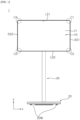
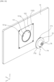
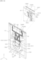
- the display device 1 may include a base 20, a pole 30, a support arm 50, and a connector 40.
- the base 20 may have the shape of a generally flat cylinder.
- the base 20 may be placed on the ground surface.
- a wheel 20W may be mounted on the lower surface of the base 20.
- the wheel 20W may include a plurality of wheels 20W. A user may freely move the display device 1 placed on the ground surface by means of the wheel 20W.
- the pole 30 may extend in a vertical direction.
- the lower end of the pole 30 may be coupled to the base 20.
- the pole 30 may be adjacent to the periphery of the base 20.
- the support arm 50 may extend in a direction which intersects the pole 30.
- the support arm 50 may extend in a direction which intersects both the pole 30 and the head 10.
- the support arm 50 may connect the head 10 to the pole 30.
- One side of the support arm 50 may be coupled to the upper end of the pole 30.
- the other side of the support arm 50 may be coupled to the rear side of the head 10.
- the other side of the support arm 50 may be coupled to the connector 40.
- the connector 40 may be coupled to the rear surface of the head 10.
- the base 20, the pole 30, the support arm 50, and the rotary connector 40 may be collectively referred to as stand 20, 30, 50 and 40. Consequently, the head 10 may be supported by the connector 40, the support arm 50, the pole 30, and the base 20, and may be spaced upwards from the ground surface.
- a power cable CW may be connected to an external power source.
- the plug Cwa of the power cable CW may be connected to a concentric plug, and the jack of the power cable CW may be connected to the base 20.
- a battery (not shown) may be installed to the base 20, the pole 30 and/or the head 10, may be charged by power supplied through the power cable CW or discharged.
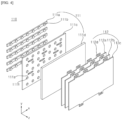
- the head 10 may include a display panel 11, a middle cabinet 12, a frame 13, an end frame 14, and a back cover 15.
- the display panel 11 may define the front surface of the head 10.
- the display panel 11 may be an OLED panel or an LED panel.
- the display panel 11 may divide an image into a plurality of pixels, and may control the color, brightness and chrominance of each of the pixels, thereby outputting the image.
- the display panel 11 may be divided into an active area, in which an image is displayed, and an inactive area, in which an image is not displayed.
- the display panel 11 may generate light corresponding to red, green or blue in response to a control signal.
- the middle cabinet 12 may extend along the periphery of the display panel 11.
- a horizontal portion 12H may be positioned in front of the display panel 11.
- a vertical portion 12V may intersect the horizontal portion 12H, and may cover the lateral side surface of the display panel 11.
- the middle cabinet 12 may include a metal or plastic material.
- the middle cabinet 12 may be referred to as a side frame or a guide panel.
- the frame 13 may be positioned behind the display panel 11. Electronic parts such as a PCB (Printed Circuit Board) may be coupled to the rear surface of the frame 13.
- the frame 13 may include a metal material.
- the frame 13 may be referred to as a mount plate or a module cover.
- the end frame 143 may define the periphery of the head 10.
- a horizontal portion 14H may be positioned in front of the horizontal portion 12H of the middle cabinet 12.
- a vertical portion 14V may cover the lateral side surface of the vertical portion 12V of the middle cabinet 12.
- the end frame 14 may include a metal or plastic material.
- the back cover 15 may define the rear surface of the head 10.
- the back cover 15 may cover the rear side of the frame 13, and may be coupled to the frame 13.
- a backlight unit 110 may be positioned between the display panel 11 and the frame 13, and may be coupled to the frame 13.
- the display panel 11 may be referred to as an LCD panel.
- the backlight unit 110 may include an optical layer 111 and an optical sheet 112.
- the optical layer 111 may include at least one of a substrate 111a, at least one light source 111b, a reflection sheet 111c, and a diffusion plate 111d.
- the substrate 111a may be coupled to the front surface of the frame 13.
- the substrate 111a may have the shape of a plate, or may be composed of a plurality of straps which are spaced apart from each other in a vertical direction.
- the at least one light source 111b may be mounted on the substrate 111a.
- the light source 111b may include an LED (Light Emitting Diode).
- An electrode pattern configured to connect an adaptor to the light source 111b may be formed on the substrate 111a.
- the reflection sheet 111c may be positioned in front of the substrate 111a.
- the reflection sheet 111c may have a hole 111h in which the light source 111b is positioned.
- the diffusion plate 111d may be positioned in front of the reflection sheet 111c.
- a spacer 111s may be disposed between the reflection sheet 111c and the diffusion plate 111d so as to support the rear surface of the diffusion plate 111d.
- the optical sheet 112 may be positioned in front of the diffusion plate 111d.
- the rear surface of the optical sheet 112 may be in close contact with the diffusion plate 111d, and the front surface of the optical sheet 112 may be in close contact with or adjacent to the rear surface of the display panel 11.
- the optical sheet 112 may include at least one of a diffusion sheet or a prism sheet.
- a coupler 112d may be formed at at least one edge of the optical sheet 112.
- the light from the light source 111b may be supplied to the display panel 11 through the diffusion plate 111d and the optical sheet 112.
- the display panel 11 according to the present disclosure may be an OLED panel or another kind of panel which does not require the above-mentioned backlight unit 110.
- a backlight unit 110' may be positioned between the display panel 11 and the frame 13, and may be coupled to the frame 13.
- the display panel 11 may be referred to as an LCD panel.
- the backlight unit 110' may include an optical layer 111' and the optical sheet 112.
- the optical layer 111' may include a substrate 111a', at least one light source 111b', a reflection sheet 111f, and a light guide plate 111e.
- the light guide plate 111e may be positioned between the frame 13 and the optical sheet 112, and may be supported by the frame 13.
- the substrate 111a' may be adjacent to the periphery of the light guide plate 111e, and may be coupled to the frame 13.
- the at least one light source 111b' may be mounted on the substrate 111a'.
- the light source 111b' may include an LED (Light Emitting Diode).
- An electrode pattern configured to connect the adaptor to the light source 111b' may be formed on the substrate 111a'.
- the reflection sheet 111f may be positioned between the frame 13 and the light guide plate 111e, and may be supported by the frame 13.
- the light from the light source 111b' may be supplied to the display panel 11 through the light guide plate 111e and the optical sheet 112.
- the display panel 11 according to the present disclosure may be an OLED panel or another kind of panel which does not require the above-mentioned backlight unit 110'.
- a plurality of electronic parts PW, MB and TC are positioned between the display panel 11 and the back cover 15.
- the plurality of electronic parts PW, MB and TC may be mounted on the front surface of the back cover 15.
- the plurality of electronic parts PW, MB and TC may be mounted on the front surface or the rear surface of the frame 13 (see FIG. 3 ) positioned in front of the back cover 15. Examples of the plurality of electronic parts PW, MB and TC are as follows.
- the power supply board PW may supply power to individual components of the display device.
- the power supply board PW may supply power to the display panel 11, the main board MB, the timing controller board TC, and a battery B (see FIG. 15 ).
- the main board MB may control the display device.
- the timing controller board TC may be electrically connected to the display panel 11 via a cable (not shown), and may supply an image signal to the display panel 11.
- the connector 40 may be a rotary connector 40.
- a user may pivot the head 10.
- the head 10 may be positioned in a horizontal mode.
- the head 10 may be positioned in a vertical mode.
- a user may tilt or swivel the head 10.
- a user may adjust the height of the head 10 by controlling the length of the pole 30.
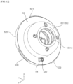
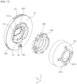
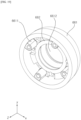
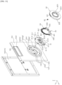
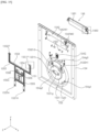
- the display device 1 may include a mount 60.
- the mount 60 may be positioned between the head 10 and the connector 40.
- the mount 60 may be coupled to the connector 40.
- the mount 60 may surround a portion of the connector 40.
- the rib 1523 of the coupling plate 152 may project rearwards from the coupling plate 152.
- the rib 1523 may extend along the periphery of the hole 1522.
- the rib 1523 may define the boundary of the hole 1522.
- the rib 1523 may include a vertical portion 1523V and a horizontal portion 1523H which extends in a direction intersecting the vertical portion 1523V.
- the horizontal portion 1523H may extend in a direction toward the center of the hole 1522 from the end of the vertical portion 1523V.
- the horizontal portion 1523H and the vertical portion 1523V may define a coupling groove 1523V and 1523H.
- the head 152 may include a base plate 151.
- the base plate 151 may be positioned between the back cover 151 and the coupling plate 152.
- the base plate 151 may be seated in the mount groove 1521 in the coupling plate 152, and may be coupled to the coupling plate 152.
- the base plate 152 may be exposed in a rearward direction of the back cover 15 through the hole 1522 in the coupling plate 152.
- the first plate 611 may include a first front groove 6113 and a second front groove 6114.
- the first front groove 6113 and the second front groove 6114 may be depressed forwards from the rear surface of the first plate 611.
- the first front groove 6113 and the second front groove 6114 may be spaced apart from each other, and may overlap each other in a rightward-and-leftward direction.
- the first front groove 6113 may be positioned to the left of the second plate 612, and the second front groove 6114 may be positioned to the right of the second plate 612.
- the second plate 612 may be formed in the center of the first plate 611.
- the second plate 612 may be formed by pressing the rear surface of the first plate 611 forwards.
- the hole 6124 in the second plate 612 may be formed through the second plate 612 in a forward-and-backward direction.
- the hole 6124 may include a plurality of holes.
- the plurality of holes 6124 may include two holes 6124 which are spaced apart from each other in a rightward-and-leftward direction.
- the second plate 612 may include a magnet holder 6121.
- the magnet holder 6121 may project rearwards from the rear surface of the second plate 612.
- the magnet holder 6121 may receive a magnet M and surround the magnet M.
- the head 10 may include a magnet (not shown) aligned with the magnet M fixed to the plate 61.
- the mount 60 disposed in the head 10 may provide magnetic coupling force. By virtue of the magnetic coupling force, the mount 60 may be attached to the head 10. Accordingly, a user can easily manipulate a knob 642 of a button 64, as described later.
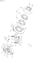
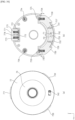
- the mount 60 may include a cover 62.
- the cover 62 may be positioned behind the plate 61, and may be coupled to the plate 61.
- a mount hole 62H may be formed in the center of the cover 62.
- a rib 62R of the cover 62 may project rearwards from the rear surface of the cover 62.
- the mount 60 may include a slider 63.
- the slider 63 may be positioned between the plate 61 and the cover 62.
- the slider 63 may be movably coupled both to the plate 61 and to the cover 62. For example, the slider 63 may move in an upward-and-downward direction.
- the slider 63 may extend in a circumferential direction of the plate 61, and may face the second plate 612.
- the slider 63 may be formed to have an arc shape.
- the slider 63 may include a first hole 631 and a second hole 632.
- Each of the first hole 631 and the second hole 632 may be a long hole which is elongated in an upward-and-downward direction.
- the first hole 631 and the second hole 632 may be spaced apart from each other in a rightward-and-leftward direction.
- the slider 63 may include a pin hole 633.
- the pin hole 633 may be positioned between the first hole 631 and the second hole 632.
- the pin hole 633 may include a first path P1 (see FIGs. 17 and 18 ) and a second path P2 (see FIGs. 17 and 18 ) which extend in directions which intersect a horizontal line HL (see FIGs. 17 and 18 ) which extends in a rightward-and-leftward direction.
- the first path P1 (see FIGs. 17 and 18 ) may extend in an inclined direction relative to the horizontal line HL (see FIGs. 17 and 18 ).
- the second path P2 (see FIGs. 17 and 18 ) may extend in an inclined direction intersecting the first path P1 (see FIGs. 17 and 18 ) and orthogonal to the horizontal line HL (see FIGs. 17 and 18 ).
- the first and second paths P1 and P2 may define an acute angle therebetween.
- the slider 63 may include a first spring 634 and a second spring 636.
- the first spring 634 and the second spring 636 may be spaced apart from each other in a rightward-and-leftward direction.
- the first spring 634 may be adjacent to the first hole 631, and the second spring 636 may be adjacent to the second hole 632.
- the first spring 634 and the second spring 636 may be compressed and restored in an upward-and-downward direction. Accordingly, the slider may be moved upwards and downwards by virtue of the first and second springs 634 and 636.
- the slider 63 may include a first holder 635 and a second holder 637.
- the first holder 635 and the second holder 637 may be formed by pressing a portion of the slider 62 forwards.
- the first spring 634 may be positioned in the first holder 635, and the second spring 636 may be positioned in the second holder 637.
- the slider 63 may include a first hook 638 and a second hook 639.
- the first hook 638 and the second hook 639 may project radially from the outer peripheral surface of the slider 63.
- the first hook 638 may be adjacent to the first hole 631, and the second hook 639 may be adjacent to the second hole 632.
- the first hook 638 may be positioned to the left of the slider 63, and the second hook 639 may be positioned to the right of the slider 63.
- the first hook 638 and the second hook 639 may be formed integrally with the slider body 63, and may be moved along with the slider 63.
- the slider 63 may be positioned below the first plate 611.
- the first spring 634 and the first holder 635 may be positioned in the first front groove 6113 in the first plate 611.
- the second spring 635 and the second holder 636 may be positioned in the second front groove 6114 in the first plate 611.
- the magnet M may be supported by the magnet holder 6121 of the first plate 611.
- the mount 60 may include a boss 64.
- the boss 63 may include a boss cap 651 and a tension spring 652 disposed in the boss cap 651.
- the boss 63 may be inserted into the boss hole 6111 in the first plate 611, and may project in a forward direction of the first plate 611.
- the boss 65 may come into contact with the boss seating portion 151g1 of the back cover 15.
- a user may determine whether the head 10 and the mount 60 are coupled to each other depending on contact between the boss 65 and the boss seating portion 151g1.
- the cover 62 may include a side portion 629.
- the side portion 629 may extend along the periphery of the cover 62 so as to form the lateral side surface of the cover 62.
- Cutout portions 6291 and 6292 may be formed in the side portion 629.
- the cutout portions 6291 and 6292 may be formed by cutting portions of the side portion 629.
- the cutout portions 6291 and 6292 may include a plurality of cutout portions.
- the plurality of cutout portions 6291 and 6292 may include a first cutout portion 6291 and a second cutout portion 6292.
- the first cutout portion 6291 may be aligned with the first hook 638, and may receive the first hook 638 therein.
- the second cutout portion 6292 may be aligned with the second hook 639, and may receive the second hook 639 therein.
- a top hook 621 may project from the side portion 629 in a radial direction of the cover 62.
- the top hook 621, the first cutout portion 6291, and the second cutout portion 6292 may be spaced apart from one another in a circumferential direction of the cover 62.
- the cover 62 may include a boss coupler 622.
- the boss 65 may be coupled to the boss coupler 622.
- the boss coupler 622 may include a body (no reference numeral) and a protrusion (no reference numeral).
- the body (no reference numeral) of the boss coupler 622 may project forwards from the cover 62, and may be formed to have the shape of a ring.
- the rear end of the boss cap 651 may come into contact with the body of the boss coupler 622, and the tension spring 652 may be positioned in the body.
- the protrusion of the boss coupler 622 may project forwards from the cover 62, and may be surrounded by the ring-shaped body.
- the cover 62 may include a second rear groove 625.
- the second rear groove 625 may be depressed rearwards from the front surface of the cover 62.
- the second rear groove 625 may extend in an upward-and-downward direction.
- the second rear groove 625 may be aligned with the second front groove 6114 in the plate 151.
- the second rear groove 625 may be spaced apart from the first rear groove 624 in a rightward-and-leftward direction.
- the first rear groove 624 may be positioned to the left of the mount hole 62H, and the second rear groove 625 may be positioned to the right of the mount hole 62H.
- the cover 62 may include a second wall 626.
- the second wall 626 may project forwards from the front surface of the cover 62.
- the second wall 626 may be positioned at the upper end of the second rear groove 625.
- the second wall 626 may extend in a direction intersecting a direction in which the second rear groove 625 extends.
- the second wall 626 may extend in a rightward-and-leftward direction.
- the cover 62 may include a first stopper 627.
- the first stopper 627 may project from the front surface of the cover 62.
- the first stopper 627 may be aligned with the first hole 631 in the slider 63.
- the first stopper 627 may be positioned below the mount hole 62H.
- the cover 62 may include a slot 62S.
- the slot 62S may be formed through the cover 61 in a forward-and-backward direction, and may be a long hole which extends in a rightward-and-leftward direction.
- the slot 62S may be aligned with the pin hole 633.
- the first rear groove 623 may be aligned with the first front groove 6113.
- the first spring 634 may be positioned between the first rear groove 623 and the first front groove 6113.
- the first spring 634 and the first holder 635 may be positioned between the first rear groove 623 and the first front groove 6113.
- the upper end of the first spring 634 may contact the first wall 624. When the slider 63 moves upwards, the first spring 634 may be compressed by the first wall 624.
- the second rear groove 624 may be aligned with the second front groove 6114.
- the second spring 636 may be positioned between the second rear groove 624 and the second front groove 6114.
- the second spring 636 and the second holder 637 may be positioned between the second rear groove 624 and the second front groove 6114.
- the upper end of the second spring 636 may contact the second wall 626. When the slider 63 moves upwards, the second spring 636 may be compressed by the second wall 626.
- the first stopper 627 may be aligned with the first hole 631 in the slider 63, and may be inserted into the first hole 631.
- the width of the fist stopper 627 in an upward-and-downward direction may be smaller than the width of the first hole 631 in an upward-and-downward direction. Consequently, the first stopper 627 may limit movement of the slider 63 in an upward-and-downward direction.
- the second stopper 628 may be aligned with the second hole 632 in the slider 63, and may be inserted into the second hole 632.
- the width of the second stopper 628 in an upward-and-downward direction may be smaller than the width of the second hole 632 in an upward-and-downward direction. Consequently, the second stopper 628 may limit movement of the slider 63 in an upward-and-downward direction.
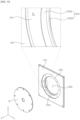
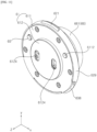
- the sleeve 66 may include a sleeve cover 661.
- the sleeve cover 661 may be open at the front surface thereof, and may be coupled to the mount hole 62H in the cover 62.
- the rib 62R of the cover 62 may extend along the periphery of the sleeve cover 661.
- a hole 6621 may be formed in the rear surface of the sleeve cover 661.
- the connector 40 (see FIG. 2 ) may be inserted into and coupled to the hole 6621 in the sleeve cover 661. At least a portion of a rotary body (not shown) of the connector 40 (see FIG. 2 ) may be inserted into the sleeve cover 661.
- the sleeve cover 661 may include a cover coupler 6611.
- the cover coupler 6611 may project inwards from the inner surface of the sleeve cover 661.
- the cover coupler 6611 may include a plurality of cover couplers.
- the plurality of cover couplers 6611 may be spaced apart from each other in a circumferential direction of the sleeve 66.
- a fastening element such as a screw may be fastened to the cover coupler 6611 through the cover 62. Consequently, the cover 62 may be coupled to the sleeve 66.
- the sleeve 66 may include inner rings 662 and 663.
- the inner rings 662 and 663 may be inserted into the sleeve cover 661.
- the inner rings 662 and 663 may include a first inner ring 662 and a second inner ring 663 positioned behind the first inner ring 662.
- the first inner ring 662 and the second inner ring 663 may be coupled to each other by means of a fastening element such as a screw.
- the central holes in the first and second inner rings 662 and 663 may be aligned with the hole 6612 in the cover 661.
- the diameter of the central hole in the first inner ring 662 may be larger than the diameter of the central hole in the second inner ring 663. Consequently, the diameters of the central holes in the inner rings 662 and 663 may be reduced rearwards.
- the mount 60 may be detachably coupled to the head 10 (see FIG. 6 ).
- the mount 60 may be detachably coupled to the coupling plate 152 (see FIGs. 6 and 9 ) of the back cover 15.
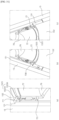
- FIG. 20 illustrates a latched state of the mount 60.
- the latched state may be referred to as a locked state or a coupled state.
- FIG. 21 illustrates an unlatched state of the mount 60.
- the unlatched state may be referred to as an unlocked state or an uncoupled state.
- the knob 642 may be movable in the slot 62S (see FIG. 15 ) rightwards and leftwards. When the knob 642 is moved in the slot 62S (see FIG. 15 ), the pin 641 may move within the pin hole 633.
- the pin 641 when the knob 642 is moved leftwards, the pin 641 may be moved along the first path P1 from the inflection point between the first path P1 and the second path P2, and the slider 63 may be raised relative to the plate 61 and the cover 62 which are coupled to each other.
- the slider 63 when the lower ends of the first and second stoppers 627 and 628 come into contact with the first and second holes 631 and 632 in the slider 63, movement of the slider 63 may be restricted.
- the slider 63 When the movement of the slider 63 is restricted by the stoppers 627 and 628, the slider 63 may be raised while compressing the first and second springs 634 and 635.
- the first and second hooks 638 and 639 may be positioned between the plate 61 and the cover 62 (a hidden state), and the mount 60 and the back cover 15 may be unlatched, thereby enabling a user to remove the mount 60 from the head 10.
- the pin 641 may be moved toward the inflection point between the first path P1 and the second path P2 along the first path P1.
- the slider 62 may be moved downwards by the restoring force of the first and second springs 634 and 635.
- the first and second hooks 638 and 639 may project in a radial direction of the mount 60 through the first and second cutout portions 6291 and 6292.
- the first and second hooks may be inserted into the coupling groove in the coupling plate 152, and the mount 60 and the back cover 15 may be converted into a latched state, thereby allowing a user to couple the mount 60 to the head 10.
- the base plate 151 may be positioned between the back cover 151 and the coupling plate 152.
- the base plate 151 may be seated in the mount groove 1521 (see FIG. 10 ) in the coupling plate 152 and may thus be coupled to the coupling plate 152.
- the base plate 152 may be exposed in a rearward direction of the back cover 15 through the hole 1522 (see FIG. 10 ) in the coupling plate 152.
- the first slider 73 may include a pin hole 733.
- the pin hole 733 may be positioned between the first hole 731 and the second hole 732.
- the pin hole 733 may include a first path P1 (see FIG. 28 ) which extends in a direction intersecting a horizontal line HL (see FIG. 28 ) which extends in a rightward-and-leftward direction.
- the pin hole 733 may include a second path P2 (see FIG. 28 ) which is connected to the first path P1 and extends parallel to the horizontal line HL (see FIG. 28 ).
- the first path P1 (see FIG. 28 ) may extend in a direction inclined relative to the horizontal line HL (see FIG. 28 ).
- the second path P2 (see FIG. 28 ) may extend in a direction intersecting the first path P1 (see FIG. 28 ).
- the first and second paths P1 and P2 (see FIG. 28 ) may define an obtuse angle therebetween.
- the first slider 73 may include a first spring 734 and a second spring 736.
- the first spring 734 and the second spring 736 may be spaced apart from each other in a rightward-and-leftward direction.
- the first spring 734 may be adjacent to the first hole 731, and the second spring 736 may be adjacent to the second hole 732.
- the first spring 734 and the second spring 736 may be compressed and restored in an upward-and-downward direction. Consequently, the first slider 73 may be moved by the springs 734 and 736 in an upward-and-downward direction.
- the first slider 73 may include a first hook 738 and a second hook 739.
- the first hook 738 and the second hook 739 may project radially from the outer peripheral surface of the slider 73.
- the first hook 738 may be positioned closer to the first hole 731 than the second hook 739, and the second hook 739 may be positioned closer to the second hole 732 than the first hook 738.
- the first hook 738 may be positioned to the left of the first slider 73, and the second hook 739 may be positioned to the right of the first slider 73.
- the first and second hooks 738 and 739 may formed integrally with the first slider 73, and may be movable together with the first slider 73.
- the first slider 73 may be positioned at a lower portion of the plate 71, and the second slider 77 may be positioned at an upper portion of the plate 71.
- the first spring 734 and the first holder 735 may be positioned in the first front groove 7113 in the plate 71.
- the second spring 735 and the second holder 736 may be positioned in the second front groove 7114 in the plate 71.
- the top spring 773 and the top holder 772 may be positioned in a top groove 7113.
- the bosses 75a and 75b may come into contact with the boss seating portion 151g of the back cover 15.
- a user may determine whether the head 10 is coupled to the mount 70 depending on contact between the bosses 75a and 75b and the boss seating portion 151g.
- the cover 72 may include a first stopper 727.
- the first stopper 727 may project forwards from the front surface of the cover 72.
- the first stopper 727 may be aligned with the first hole 731 in the first slider 73, and may be inserted into the second hole 731.
- the first stopper 727 may extend in an upward-and-downward direction.
- the length of the first stopper 727 in an upward-and-downward direction may be less than the width of the first hole 731 in an upward-and-downward direction.
- the cover 72 may include a second stopper 728.
- the second stopper 728 may project forwards from the front surface of the cover 72.
- the second stopper 728 may be aligned with the second hole 732 in the first slider 73, and may be inserted into the second hole 732.
- the second stopper 728 may extend in an upward-and-downward direction.
- the length of the second stopper 728 in an upward-and-downward direction may be less than the width of the second hole 732 in an upward-and-downward direction.
- the cover 72 may include a slot 72S.
- the slot 72S may be formed through the cover 72 in a forward-and-backward direction, and may be a long hole which is elongated in a rightward-and-leftward direction.
- the slot 72S may be aligned with the pin hole 733 in the first slider 73.
- the mount 70 may include a button 74.
- the button 74 may be positioned between the first slider 74 and the cover 72.
- the button 74 may include a pin 741, which projects forwards from the button 74, and a knob 742, which projects rearwards from the button 74.
- the pin 741 may be inserted into the pin hole 733 in the first slider 73.
- the knob 742 may be inserted into the slot 72S in the cover 72, and may project in a rearward direction of the cover 72.
- the width of the knob 742 in a rightward-and-leftward direction may be less than the width of the slot 72S in a rightward-and-leftward direction. Consequently, the knob 742 may be movable in the slot 72S in a rightward-and-leftward direction.
- the mount 70 may be detachably coupled to the head 10 (see FIG. 6 ).
- the mount 70 may be detachably coupled to the coupling plate 152 (see FIG. 22 ) of the back cover 15.
- FIGs. 29 and 30 are views illustrating the latched state of the mount 70.
- the latched state may be referred to as a locked state or a coupled state.
- FIG. 28 is a view illustrating the unlatched state of the mount 60.
- the unlatched state may be referred to as an unlocked state or an uncoupled state.
- the top hook 771 may be movable in an upward-and-downward direction by the top spring 773.
- the top spring 773 may be compressed.
- the top hook 771 may project in an outward direction of the mount 70 by the restoring force of the top spring 773, and may be latched to the coupling plate 152.
- the first and second hooks 738 and 739 may be converted into a latched state or an unlatched state.
- the knob 742 is moved in the slot 72S in a rightward-and-leftward direction
- the pin 741 is moved in the pin hole 733.
- the pin 741 when the knob 742 is moved leftwards, the pin 741 may be moved along the first path P from the first path P1 and the second path P2, and the slider may be raised relative to the plate 71 and the cover 72 which are coupled to each other.
- the lower ends of the first and second stoppers 727 and 728 may come into contact with the first and second holes 731 and 728 in the slider 62, thereby restricting movement of the slider 73.
- the slider 73 may be moved upwards while compressing the first and second springs 734 and 736.
- the first and second hooks 738 and 739 may be positioned between the plate 71 and the cover 72 (a hidden state), releasing the mount 70 and the back cover 75 from the latched state and thereby allowing a user to remove the mount 70 from the head 10.
- the pin 741 may be moved along the second path P2 from the first path P1.
- the slider 72 may be moved downwards by the restoring force of the first and second springs 734 and 735.
- the first and second stoppers 727 and 728 catch on the first and second holes 731 and 732, movement of the slider 73 may be restricted.
- the first and second hooks 738 and 739 may project through the first and second cutout portions 7291 and 7292 in a radial direction of the mount 70, and may then be inserted into the coupling groove in the coupling plate 152. Consequently, the mount 70 and the back cover 15 may be latched, thereby allowing a user to couple the mount 70 to the head 10.
- a user may couple the first and second hooks 738 and 739 by first coupling the top hook 771 and then manipulating the button 74.
- a user may latch the first and second hooks 738 and 739 to the coupling groove by moving the knob 742 rightwards after coupling the top 771. Consequently, the mount 70 may be coupled to the head 10.
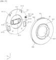
- a user may move the knob leftwards to release the first and second hooks 738 and 739 from the state latched to the coupling groove. Subsequently, a user may draw the mount 70 out of the head 10 downwards.
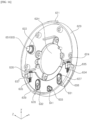
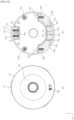
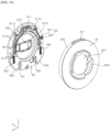
- the head 10 may include a mount portion 15G, and a base plate 153 and a coupling plate 154 which are coupled to the mount portion 15G.
- the mount portion 15G may be formed at the back cover 15.
- the base plate 153 may have the shape of a circle.
- the mount 80 may be seated on the base plate 153.
- the base plate 153 may include a first part 1531 and a second part 1532.
- the first part 1531 may be depressed forwards from the second part 1532.
- the first part 1531 may include two holes 1531h which are respectively aligned with two holes 8124 in the first plate 81.
- a magnet groove 1531g (see FIG. 34 ) into which a magnet (not shown) is inserted may be formed in the rear surface of the first part 1531.
- the magnet groove 1531g (see FIG. 34 ) may be positioned between the two holes 8124 in the first part 1531.
- the second part 1532 may include a boss seating portion 1532g1.
- the boss seating portion 1532g1 may be a groove which is depressed forwards from the rear surface of the second part 1532.
- the second part 1532 may include a protrusion seating portion 1532g2.
- the protrusion seating portion 1532g2 may be a groove which is depressed forwards from the rear surface of the second part 1532.
- the protrusion seating portion 1532g2 may be spaced apart from the boss seating portion 1532g1 in a rightward-and-leftward direction.
- the protrusion seating portion 1532g2 may be positioned to the left of the first part 1531, and the boss seating portion 1532g1 may be positioned to the right of the first part 1531.
- the second part 1532 may include rear pin holes 1532h1 and 1532h2.
- Each of the rear pin holes 1532h1 and 1532h2 may be a long hole which extends in an upward-and-downward direction.
- the rear pin holes 1532h1 and 1532h2 may include a plurality of rear pin holes.
- the rear pin holes 1532h1 and 1532h2 may include a first rear pin hole 1532h1 and a second rear pin hole 1532h2 which are spaced apart from each other.
- the first rear pin hole 1532h1 may be positioned to the left of the first part 1531.
- the second rear pin hole 1532h2 may be positioned to the right of the first part 1531.
- the coupling plate 154 may include a handle mounting portion 1542.
- the handle mounting portion 1542 may be positioned adjacent to the upper side of the coupling plate 154.
- the handle mounting portion 1542 may be a groove which is formed by depressing a portion of the coupling plate 154 forwards.
- a handle 156 which will be described later, may be inserted into and coupled to the handle mounting portion 1542.
- a first shaft pin hole 1542H2 may be formed in the side wall 1542W2.
- the first shaft pin hole 1542H2 may be formed through the side wall 1542W2 in a rightward-and-leftward direction.
- a shaft pin 1542P may be inserted into the first shaft pin hole 1542H2.
- the first shaft pin hole 1542H2 may be formed in each of two shaft walls 1542W2.
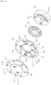
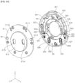
- the mount 80 may include a cover 82.
- the cover 82 may be positioned behind the plate 81, and may be coupled to the plate 81.
- the cover 82 may have a mount hole 82H formed in the center thereof.
- a rib 82R of the cover 82 may project rearwards from the rear surface of the cover 82.
- the sleeve 66 (see FIGs. 17 to 19 ) may be coupled to the mount hole 82H2 in the cover 82.
- the cover 82 may include a side portion 829.
- the side portion 829 may extend along the periphery of the cover 82 to form the side surface of the cover 82.
- Cutout portions 8291 and 8292 may be formed in the side portion 829.
- the cutout portions 8291 and 8292 may be formed by cutting portions of the side portion 829.
- the cutout portions 8291 and 8292 may include a plurality of cutout portions.
- the plurality of cutout portions 8291 and 8292 may include a first cutout portion 8291 and a second cutout portion 8292.
- the first cutout portion 8291 may be aligned with the first hook 838, and may receive the first hook 838 therein.
- the second cutout portion 8292 may be aligned with the second hook 839, and may receive the second hook 839 therein.
- the top hook 821 may project from the side portion 829 in a radial direction of the cover 82.
- the top hook 821, the first cutout portion 8291 and the second cutout portion 8292 may be spaced apart from one another in a circumferential direction of the cover 82.
- the cover 82 may include a boss coupler 822.
- a boss 85 may be coupled to the boss coupler 822.
- the boss coupler 822 may include a body (no reference numeral) and a protrusion (no reference numeral).
- the body of the boss coupler 822 may project forwards from the cover 82, and may have the shape of a ring.
- the rear end of a boss cap 851 may come into contact with the body of the boss coupler 822, and a tension spring 852 may be positioned in the body.
- the protrusion of the boss coupler 822 may project forwards from the cover 82, and may be surrounded by the ring-shaped body.
- the cover 82 may include a first wall 824.
- the first wall 824 may project forwards from the front surface of the cover 82.
- the first wall 824 may be positioned at the upper end of the first rear groove 823.
- the first wall 824 may extend in a direction intersecting a direction in which the first rear groove 823 extends.
- the first wall 824 may extend in a rightward-and-leftward direction.
- the cover 82 may include a second stopper 828.
- the second stopper 828 may project forwards from the front surface of the cover 82.
- the second stopper 828 may be aligned with a second hole 832 in the slider 83.
- the second stopper 828 may be positioned below the mount hole 82H.
- the first stopper 827 and the second stopper 828 may be disposed below the mount hole 82H, and may be spaced apart from each other in a rightward-and-leftward direction.
- the first stopper 827 may be positioned to the left of the second stopper 828, and the second stopper 828 may be positioned to the right of the first stopper 827.
- the cover 82 may include the second stopper 828.
- the mount 80 may include the boss 85.
- the boss 85 may include the boss cap 851 and the tension spring 852 inserted into the boss cap 851.
- the boss 85 may be inserted into the boss hole 8111 in the first plate 811, and may project in a forward direction of the first plate 811.
- the boss 85 may come into contact with the boss seating portion 153g1 of the back cover 15.
- a user may determine whether the head 10 is coupled to the mount 80 depending on contact between the boss 85 and the boss seating portion 153g1.
- the mount 80 may include the slider 83.
- the slider 83 may be positioned between the plate 81 and the cover 82.
- the slider 83 may be movably coupled to the plate 81 and the cover 82.
- the slider 82 may be movable in an upward-and-downward direction.
- the slider 83 may extend in a circumferential direction of the plate 81, and may face the second plate 812.
- the slider 83 may be formed to have an arc shape.
- the slider 83 may include the first hole 831 and the second hole 832.
- Each of the first hole 831 and the second hole 832 may be a long hole which extends in an upward-and-backward direction.
- the first hole 831 and the second hole 832 may be spaced apart from each other in a rightward-and-leftward direction.
- the slider 83 may include a first spring 834 and a second spring 836.
- the first spring 834 and the second spring 836 may be spaced apart from each other in a rightward-and-leftward direction.
- the first spring 834 may be adjacent to the first hole 831, and the second spring 836 may be adjacent to the second hole 832.
- the first spring 834 and the second spring 836 may be compressed and restored in an upward-and-downward direction. Consequently, the slider 3 may be movable in an upward-and-downward direction by the springs 834 and 836.
- the slider may include a first holder 835 and a second holder 837.
- the first holder 835 and the second holder 837 may be formed by pressing a portion of the slider 83 forwards.
- the first spring 834 may be positioned in the first holder 835, and the second holder 837 may be positioned in the second holder 837.
- the slider 83 may include the first hook 838 and the second hook 839.
- the first hook 838 and the second hook 839 may project radially from the outer peripheral surface of the slider 83.
- the first hook 838 may be adjacent to the first hole 831, and the second hook 839 may be adjacent to the second hole 832.
- the first hook 838 may be positioned to the left of the slider 83, and the second hook 839 may be positioned to the right of the slider 83.
- the first and second hooks 838 and 839 may be formed integrally with the slider 83, and may be moved along with the slider 83.
- the slider 83 may be positioned at a lower portion of the first plate 811.
- the first spring 834 and the first holder 835 may be positioned in the first front groove 8113 in the first plate 811.
- the second spring 835 and the second holder 836 may be positioned in the second front groove 8114 in the first plate 811.
- the mount 80 may include a link connector 84 coupled to the slider 83.
- the link connector 84 may extend upwards from the slider 83, and may extend along the boundary between the second plate 812 and the first plate 811.
- the link connector 84 may include a first pin 841 and a second pin 842.
- the first pin 841 may be aligned with the first front pin hole 8115, the first rear pin hole 1532h1 and the first pin hole 1551H.
- the first pin 841 may sequentially pass through the first pin hole 8115, the first rear pin hole 1532h1 and the first pin hole 1551H.
- the second pin 842 may be aligned with the second front pin hole 8116, the second rear pin hole 1532h2 and the second pin hole 1552H.
- the second pin 842 may sequentially pass through the second front pin hole 8116, the second rear pin hole 1532h2 and the second pin hole 1552H.
- the link connector 84 may be formed integrally with the slider 83.
- the mount 80 may be detachably coupled to the head 10 (see FIG. 32 ).
- the mount 80 may be detachably coupled to the coupling plate 154 (see FIG. 32 ) of the back cover 15.
- a user may separate the mount 80 from the head 10 by rotating the handle 156 in the first rotational direction RD1 (see FIG. 34 ).
- a user may couple the mount 80 to the head 10 by rotating the handle 156 in the second rotational direction RD2 (see FIG. 34 ).
- a user may seat the mount 80 on the base plate 154 such that the first hook 838, the second hook 839 and the top hook 821 are respectively aligned with the first guide groove 154g1, the second guide groove 154g2 and the third guide groove 154g3, and may couple the mount 80 to the head 10 by rotating the handle 156 in the second rotational direction RD2 (see FIG. 34 ).
- the coupling pins 1551P and 1552P of the link 155 may sequentially pass through the first area A1, the third area A3 and the second area A2 of the second link pin hole 1564 by the rotation of the handle 156.
- the coupling pins 1551P and 1552P may be positioned in the third area A3 of the second link pin hole 1564, and the pins 841 and 842 of the link connector 84 may be inserted into the first pin hole 1551H.
- a user may separate the mount 80 from the head 10 by rotating the handle 156 in the second rotational direction RD2 (see FIG. 34 ).
- the coupling pins 1551P and 1552P of the link 155 may sequentially pass through the second area A2, the third area A3 and the first area A1 of the second link pin hole 1564 by the rotation of the handle 156.
- the coupling pins 1551P and 1552P may be positioned in the first area A1 of the second link pin hole 1564, and the pins 841 and 842 of the link connector 84 may be separated from the first rear pin hole 1532h1 and the first pin hole 1551H.
- the display device may include: the head 10 including the display panel 11; the stand 20, 30, 50 and 40 supporting the head 10 and detachably coupled to the head 10; and the mount 60, 70 and 80 fixed to the stand 20, 30, 50 and 40 between the head 10 and the stand 20, 30, 50 and 40, wherein the mount 60, 70 and 80 may include the slider 63, 73 and 83 coupled to the inside of the mount 60, 70 and 80 and moved in the first direction from one side of the head 10 toward another side of the head 10 or in the second direction opposite to the first direction; and the hook 638, 639, 738, 739, 838 and 839 which extends in the outward direction of the mount 60, 70 and 80 from the slider 63, 73 and 83 in the mount 60, 70 and 80 and which is moved along with the slider 63, 73 and 83.
- the mount 60, 70 and 80 may include: the plate 61, 71 and 81 positioned in front of the slider 63, 73 and 83; the cover 62, 72 and 82 coupled to the plate 61, 71 and 81 and opposite to the plate 61, 71 and 81 with respect to the slider 63, 73 and 83; a wall 624, 626, 724, 726, 824 and 826 which protrudes toward the plate 61, 71 and 81 from the cover 62, 72 and 82 and which is positioned above the slider 63, 73 and 83; and the spring 634, 636, 734, 736, 834 and 836 which includes one end fixed to the slider 63, 73 and 83 and the other end fixed to the wall 624, 626, 724, 726, 824 and 826, and which is compressed in the second direction.
- the mount 60, 70 and 80 may include: the stopper 627, 628, 727, 728, 827 and 828 which protrudes from the cover 62, 72 and 82 and which has a long side in the first direction or in the second direction; and a hole 631, 632, 731, 732, 831 and 832 which is formed at the slider 63, 73 and 83 and into which the stopper 627, 628, 727, 728, 827 and 828 is inserted, wherein the width of the hole 631, 632, 731, 732, 831 and 832 in the first direction or in the second direction may be greater than the long side of the stopper 627, 628, 727, 728, 827 and 828, and the width of the hole 631, 632, 731, 732, 831 and 832 in the first direction and in the second direction may be equal to the length of the short side of the stopper 627, 628, 727, 728, 827 and 828.
- the head 10 may include: a back cover 15 which is positioned behind the display panel 11 and to which the display panel 11 is coupled; a coupling plate 152 and 154 which is formed at the back cover 15 and to which the mount 60, 70 and 80 is coupled; and a rib 152 and 154 which is formed at the coupling plate 152 and 154, which surrounds the mount 60, 70 and 80, and at which the coupling groove 1523V, 1523H, 1541g1, 1542g2 and 154g3 is formed, wherein the hook 638, 639, 738, 739, 838 and 839 may be moved in the first direction and may be inserted into the coupling groove 1523V, 1523H, 154g1, 154g2 and 154g3, and the hook 638, 639, 738, 739, 838 and 839 may be moved in the second direction and may be positioned in the mount 60, 70 and 80.
- the hook 638, 639, 738, 739, 838 and 839 may include: a first hook 638, 738 and 838; and a second hook 639, 739 and 839 which is spaced apart from the first hook 638, 738 and 838 in a perimeter direction of the mount 60, 70 and 80, and the cover may include the side portion 629, 729 and 829 which extends along a periphery of the cover 62, 72 and 82 and which forms the side surface of the cover 62, 72 and 82, wherein side portion 629, 729 and 829 may include the first cutout portion 6291, 7291 and 8291 which is aligned in the radial direction of the mount 60, 70 and 80, and the second cutout portion 6292 and 7292 and 8292 which is aligned in the radial direction of the mount 60, 70 and 80.
Landscapes
- Engineering & Computer Science (AREA)
- General Engineering & Computer Science (AREA)
- Mechanical Engineering (AREA)
- Physics & Mathematics (AREA)
- Nonlinear Science (AREA)
- General Physics & Mathematics (AREA)
- Crystallography & Structural Chemistry (AREA)
- Optics & Photonics (AREA)
- Mathematical Physics (AREA)
- Chemical & Material Sciences (AREA)
- Theoretical Computer Science (AREA)
- Human Computer Interaction (AREA)
- Computer Hardware Design (AREA)
- Devices For Indicating Variable Information By Combining Individual Elements (AREA)
Abstract
Description
- The present disclosure relates to a display device.
- With the development of information society, demand for various kinds of display devices is increasing. In response to this demand, various kinds of display devices, such as LCDs (Liquid Crystal Displays), PDPs (Plasma Display Panels), ELDs (Electro luminescent Displays), VFDs (Vacuum Fluorescent Displays) and OLED (Organic Light-Emitting Diode) displays have recently been researched and used.
- Thereamong, an LCD panel includes a TFT substrate and a color substrate, which face each other with a liquid crystal layer interposed therebetween, in order to display an image using light supplied from a backlight unit. Meanwhile, an OLED panel is configured to display an image using a self-luminescent organic layer deposited on a substrate having a transparent electrode formed thereon.
- In recent years, a great deal of research is being conducted on an attachment and detachment structure between a display and a stand.
- It is an object of the present disclosure to solve the above and other problems.
- Another object may be to provide a display device including a stand supporting a head.
- Another object may be to provide a structure capable of freely adjusting an angle and a height of the head.
- Another object may be to provide a structure capable of freely changing position of the stand supporting the head.
- Another object may be to provide an attachment and detachment structure between the head and the stand.
- Another object may be to provide an automatic fastening structure between the head and the stand.
- In accordance with an aspect of the present disclosure for achieving the above and other objects, a display device includes: a head including a display panel; a stand supporting the head and detachably coupled to the head; and a mount positioned between the head and the stand and fixed to the stand, wherein the mount includes: a slider coupled in the mount and moved in a first direction from one side of the head toward another side of the head or in a second direction opposite to the first direction; and a hook extending from the slider in an outward direction of the mount from an inside of the mount, and moving along with the slider.
- The effects of the display device according to the present disclosure will be described as follows.
- According to at least one of embodiments of the present disclosure, it is possible to provide a display device including a stand supporting a head.
- According to at least one of embodiments of the present disclosure, it is possible to provide a structure capable of freely adjusting an angle and a height of the head.
- According to at least one of embodiments of the present disclosure, it is possible to provide a structure capable of freely changing position of the stand supporting the head.
- According to at least one of embodiments of the present disclosure, it is possible to provide an attachment and detachment structure between the head and the stand.
- According to at least one of embodiments of the present disclosure, it is possible to provide an automatic fastening structure between the head and the stand.
- The additional scope of applicability of the present disclosure will be apparent from the above detailed description. However, those skilled in the art will appreciate that various modifications and alterations are possible, without departing from the idea and scope of the present disclosure, and therefore it should be understood that the detailed description and specific embodiments, such as the preferred embodiments of the present disclosure, are provided only for illustration.
-
FIGS. 1 to 42 are diagrams illustrating examples of a display device according to embodiments of the present disclosure. - A description will now be given in detail according to exemplary embodiments disclosed herein, with reference to the accompanying drawings. For the sake of brevity of description with reference to the drawings, the same or equivalent components are denoted by the same reference numbers, and a description thereof will not be repeated.
- In general, suffixes such as "module" and "unit" used to refer to elements or components herein are merely intended to facilitate description of the specification, and the suffixes do not have any special meaning or function.
- In the present disclosure, that which is well known to one of ordinary skill in the relevant art has generally been omitted for the sake of brevity. The accompanying drawings are used to facilitate understanding of various technical features, and it should be understood that the embodiments presented herein are not limited by the accompanying drawings. As such, the present disclosure should be construed to extend to any alterations, equivalents and substitutes, in addition to those that are particularly set out in the accompanying drawings.
- It is to be understood that, although the terms "first," "second," etc. may be used herein to describe various elements, these elements should not be limited by these terms. These terms are only used to distinguish one element from another.
- It will be understood that when an element is referred to as being "connected to" another element, intervening elements may be present. In contrast, it will be understood that when an element is referred to as being "directly connected to" another element, there are no intervening elements present.
- A singular representation may include a plural representation unless the context clearly indicates otherwise.
- In the present disclosure, it should be understood that the terms "comprises," "includes," "has," etc. specify the presence of features, numbers, steps, operations, elements, components, or combinations thereof described in the specification, but do not preclude the presence or addition of one or more other features, numbers, steps, operations, elements, components, or combinations thereof.
- Indication of directions of upward U, downward D, leftward Le, rightward Ri, forward F, and rearward R is merely for convenience of description, and the technical idea disclosed in the present disclosure is not limited thereto.
- Referring to
FIGs. 1 and2 , thedisplay device 1 may include ahead 10. Thehead 10 may display an image. Thehead 10 may be referred to as adisplay 10 or a display unit. - The
head 10 may include a first long side LS1, a second long side LS2 opposite to the first long side LS1, a first short side SS1 adjacent to the first long side LS1 and the second long side LS2, and a second short side SS2 opposite to the first short side SS1. Although each of the first and second long sides LS1 and LS2 is illustrated and described as being longer than each of the first and second short sides SS1 and SS2 for convenience of explanation, the length of each of the first and second long sides LS1 and LS2 may be almost the same as that of each of the first and second short sides SS1 and SS2. - A direction parallel to the short sides SS1 and SS2 of the
head 10 may be referred to as a first direction or up-and-down direction DR1. A direction parallel to the long sides LS1 and LS2 of thehead 10 may be referred to as a second direction or rightward-and-leftward direction DR3. - A direction in which the
head 10 displays an image may be referred to as a forward direction F or z, and the direction opposite the forward direction may be referred to as a rearward direction R. A direction toward the first short side SS1 may be referred to as a leftward direction Le or x. A direction toward the second short side SS2 may be referred to as a rightward direction Ri. A direction toward the first long side LS1 may be referred to as an upward direction U or y. A direction toward the second long side LS2 may be referred to as a downward direction D. - The first long side LS1, the second long side LS2, the first short side SS1, and the second short side SS2 may be referred to as an edge of the
head 10. Points at which the first long side LS1, the second long side LS2, the first short side SS1, and the second short side SS2 meet each other may be referred to as corners. - The point at which the first short side SS1 and the second long side LS1 meet each other may be a first corner C1. The point at which the first short side SS1 and the second long side LS2 meet each other may be a second corner C2. The point at which the second short side SS2 and the second long side LS2 meet each other may be a third corner C3. The point at which the second short side SS2 and the first long side LS1 meet each other may be a fourth corner C4.
- The
display device 1 may include abase 20, apole 30, asupport arm 50, and aconnector 40. - The
base 20 may have the shape of a generally flat cylinder. Thebase 20 may be placed on the ground surface. Awheel 20W may be mounted on the lower surface of thebase 20. Thewheel 20W may include a plurality ofwheels 20W. A user may freely move thedisplay device 1 placed on the ground surface by means of thewheel 20W. - The
pole 30 may extend in a vertical direction. The lower end of thepole 30 may be coupled to thebase 20. Thepole 30 may be adjacent to the periphery of thebase 20. - The
support arm 50 may extend in a direction which intersects thepole 30. Thesupport arm 50 may extend in a direction which intersects both thepole 30 and thehead 10. Thesupport arm 50 may connect thehead 10 to thepole 30. One side of thesupport arm 50 may be coupled to the upper end of thepole 30. The other side of thesupport arm 50 may be coupled to the rear side of thehead 10. The other side of thesupport arm 50 may be coupled to theconnector 40. - The
connector 40 may be coupled to the rear surface of thehead 10. - The
base 20, thepole 30, thesupport arm 50, and therotary connector 40 may be collectively referred to as stand 20, 30, 50 and 40. Consequently, thehead 10 may be supported by theconnector 40, thesupport arm 50, thepole 30, and thebase 20, and may be spaced upwards from the ground surface. - A power cable CW may be connected to an external power source. The plug Cwa of the power cable CW may be connected to a concentric plug, and the jack of the power cable CW may be connected to the
base 20. A battery (not shown) may be installed to thebase 20, thepole 30 and/or thehead 10, may be charged by power supplied through the power cable CW or discharged. - Referring to
FIGs. 2 and3 , thehead 10 may include adisplay panel 11, amiddle cabinet 12, aframe 13, anend frame 14, and aback cover 15. - The
display panel 11 may define the front surface of thehead 10. For example, thedisplay panel 11 may be an OLED panel or an LED panel. Thedisplay panel 11 may divide an image into a plurality of pixels, and may control the color, brightness and chrominance of each of the pixels, thereby outputting the image. Thedisplay panel 11 may be divided into an active area, in which an image is displayed, and an inactive area, in which an image is not displayed. Thedisplay panel 11 may generate light corresponding to red, green or blue in response to a control signal. - The
middle cabinet 12 may extend along the periphery of thedisplay panel 11. Ahorizontal portion 12H may be positioned in front of thedisplay panel 11. Avertical portion 12V may intersect thehorizontal portion 12H, and may cover the lateral side surface of thedisplay panel 11. For example, themiddle cabinet 12 may include a metal or plastic material. Themiddle cabinet 12 may be referred to as a side frame or a guide panel. - The
frame 13 may be positioned behind thedisplay panel 11. Electronic parts such as a PCB (Printed Circuit Board) may be coupled to the rear surface of theframe 13. For example, theframe 13 may include a metal material. Theframe 13 may be referred to as a mount plate or a module cover. - The end frame 143 may define the periphery of the
head 10. Ahorizontal portion 14H may be positioned in front of thehorizontal portion 12H of themiddle cabinet 12. Avertical portion 14V may cover the lateral side surface of thevertical portion 12V of themiddle cabinet 12. For example, theend frame 14 may include a metal or plastic material. - The
back cover 15 may define the rear surface of thehead 10. Theback cover 15 may cover the rear side of theframe 13, and may be coupled to theframe 13. - Referring to
FIGs. 3 and4 , abacklight unit 110 may be positioned between thedisplay panel 11 and theframe 13, and may be coupled to theframe 13. Here, thedisplay panel 11 may be referred to as an LCD panel. Thebacklight unit 110 may include anoptical layer 111 and anoptical sheet 112. Theoptical layer 111 may include at least one of asubstrate 111a, at least onelight source 111b, areflection sheet 111c, and adiffusion plate 111d. - The
substrate 111a may be coupled to the front surface of theframe 13. Thesubstrate 111a may have the shape of a plate, or may be composed of a plurality of straps which are spaced apart from each other in a vertical direction. The at least onelight source 111b may be mounted on thesubstrate 111a. For example, thelight source 111b may include an LED (Light Emitting Diode). An electrode pattern configured to connect an adaptor to thelight source 111b may be formed on thesubstrate 111a. Thereflection sheet 111c may be positioned in front of thesubstrate 111a. Thereflection sheet 111c may have a hole 111h in which thelight source 111b is positioned. Thediffusion plate 111d may be positioned in front of thereflection sheet 111c. Aspacer 111s may be disposed between thereflection sheet 111c and thediffusion plate 111d so as to support the rear surface of thediffusion plate 111d. - The
optical sheet 112 may be positioned in front of thediffusion plate 111d. The rear surface of theoptical sheet 112 may be in close contact with thediffusion plate 111d, and the front surface of theoptical sheet 112 may be in close contact with or adjacent to the rear surface of thedisplay panel 11. Theoptical sheet 112 may include at least one of a diffusion sheet or a prism sheet. Acoupler 112d may be formed at at least one edge of theoptical sheet 112. - Consequently, the light from the
light source 111b may be supplied to thedisplay panel 11 through thediffusion plate 111d and theoptical sheet 112. Alternatively, thedisplay panel 11 according to the present disclosure may be an OLED panel or another kind of panel which does not require the above-mentionedbacklight unit 110. - Referring to
FIGs. 3 and5 , a backlight unit 110' may be positioned between thedisplay panel 11 and theframe 13, and may be coupled to theframe 13. Here, thedisplay panel 11 may be referred to as an LCD panel. The backlight unit 110' may include an optical layer 111' and theoptical sheet 112. The optical layer 111' may include asubstrate 111a', at least onelight source 111b', areflection sheet 111f, and alight guide plate 111e. Thelight guide plate 111e may be positioned between theframe 13 and theoptical sheet 112, and may be supported by theframe 13. - The
substrate 111a' may be adjacent to the periphery of thelight guide plate 111e, and may be coupled to theframe 13. The at least onelight source 111b' may be mounted on thesubstrate 111a'. For example, thelight source 111b' may include an LED (Light Emitting Diode). An electrode pattern configured to connect the adaptor to thelight source 111b' may be formed on thesubstrate 111a'. Thereflection sheet 111f may be positioned between theframe 13 and thelight guide plate 111e, and may be supported by theframe 13. - Consequently, the light from the
light source 111b' may be supplied to thedisplay panel 11 through thelight guide plate 111e and theoptical sheet 112. Alternatively, thedisplay panel 11 according to the present disclosure may be an OLED panel or another kind of panel which does not require the above-mentioned backlight unit 110'. - Referring to
FIG. 6 , a plurality of electronic parts PW, MB and TC are positioned between thedisplay panel 11 and theback cover 15. For example, the plurality of electronic parts PW, MB and TC may be mounted on the front surface of theback cover 15. In another embodiment, the plurality of electronic parts PW, MB and TC may be mounted on the front surface or the rear surface of the frame 13 (seeFIG. 3 ) positioned in front of theback cover 15. Examples of the plurality of electronic parts PW, MB and TC are as follows. - The power supply board PW may supply power to individual components of the display device. For example, the power supply board PW may supply power to the
display panel 11, the main board MB, the timing controller board TC, and a battery B (seeFIG. 15 ). The main board MB may control the display device. The timing controller board TC may be electrically connected to thedisplay panel 11 via a cable (not shown), and may supply an image signal to thedisplay panel 11. - Referring to
FIGs. 7 and8 in conjunction withFIG. 6 , theconnector 40 may be arotary connector 40. A user may pivot thehead 10. Referring to the left figure ofFIG. 7 , thehead 10 may be positioned in a horizontal mode. Referring to the right figure ofFIG. 7 , thehead 10 may be positioned in a vertical mode. Referring toFIG. 8 , a user may tilt or swivel thehead 10. A user may adjust the height of thehead 10 by controlling the length of thepole 30. - The
display device 1 may include a mount 60. The mount 60 may be positioned between thehead 10 and theconnector 40. The mount 60 may be coupled to theconnector 40. The mount 60 may surround a portion of theconnector 40. - Referring to
FIGs. 9 and10 , thehead 10 may include amount surface 15G. Themount surface 15G may be formed in the center of the rear surface of theback cover 15, and may be aligned with the mount 60. - The
head 10 may include acoupling plate 152. Thecoupling plate 152 may be mounted on themount surface 15G of theback cover 15. Themount groove 1521 in thecoupling plate 152 may be formed by depressing the front surface of thecoupling plate 152 rearwards. Thehole 1522 in the coupling plate may be formed in the center of thecoupling plate 152. Thehole 1522 may be formed through themount groove 1521 forward and backward. - The
rib 1523 of thecoupling plate 152 may project rearwards from thecoupling plate 152. Therib 1523 may extend along the periphery of thehole 1522. Therib 1523 may define the boundary of thehole 1522. Therib 1523 may include avertical portion 1523V and ahorizontal portion 1523H which extends in a direction intersecting thevertical portion 1523V. Thehorizontal portion 1523H may extend in a direction toward the center of thehole 1522 from the end of thevertical portion 1523V. Thehorizontal portion 1523H and thevertical portion 1523V may define acoupling groove - The
head 152 may include abase plate 151. Thebase plate 151 may be positioned between theback cover 151 and thecoupling plate 152. Thebase plate 151 may be seated in themount groove 1521 in thecoupling plate 152, and may be coupled to thecoupling plate 152. Thebase plate 152 may be exposed in a rearward direction of theback cover 15 through thehole 1522 in thecoupling plate 152. - The
base plate 151 may include a boss seating portion 151g1. The boss seating portion 151g1 may be a groove which is depressed forwards from the rear surface of thebase plate 151. - The
base plate 151 may include a protrusion seating portion 151g2. The protrusion seating portion 151g2 may be a groove which is depressed forwards from the rear surface of thebase plate 151. The protrusion seating portion 151g2 and the boss seating portion 151g1 may be spaced apart from each other. The protrusion seating portion 151g2 and the boss seating portion 151g1 may overlap each other in a rightward-and-leftward direction. - Referring to
FIGs. 11 ,12 and13 , the mount 60 may include aplate 61. Theplate 61 may include afirst plate 611 and asecond plate 612 which projects forwards from thefirst plate 611. Thefirst plate 611 and thesecond plate 612 may be formed integrally with each other. - The
first plate 611 may include aboss hole 6111. Theboss hole 6111 may be formed through thefirst plate 611 in a forward-and-backward direction, may be aligned with the boss seating portion 151g1 of thebase plate 151. - The
first plate 611 may include aprotrusion 6112. Theprotrusion 6112 may project forwards from thefirst plate 611, and may be aligned with the protrusion seating portion 151g2 of thebase plate 151. - The
first plate 611 may include afirst front groove 6113 and asecond front groove 6114. Thefirst front groove 6113 and thesecond front groove 6114 may be depressed forwards from the rear surface of thefirst plate 611. Thefirst front groove 6113 and thesecond front groove 6114 may be spaced apart from each other, and may overlap each other in a rightward-and-leftward direction. Thefirst front groove 6113 may be positioned to the left of thesecond plate 612, and thesecond front groove 6114 may be positioned to the right of thesecond plate 612. - The
second plate 612 may be formed in the center of thefirst plate 611. Thesecond plate 612 may be formed by pressing the rear surface of thefirst plate 611 forwards. Thehole 6124 in thesecond plate 612 may be formed through thesecond plate 612 in a forward-and-backward direction. Thehole 6124 may include a plurality of holes. For example, the plurality ofholes 6124 may include twoholes 6124 which are spaced apart from each other in a rightward-and-leftward direction. - The
second plate 612 may include amagnet holder 6121. Themagnet holder 6121 may project rearwards from the rear surface of thesecond plate 612. Themagnet holder 6121 may receive a magnet M and surround the magnet M. - The
head 10 may include a magnet (not shown) aligned with the magnet M fixed to theplate 61. The mount 60 disposed in thehead 10 may provide magnetic coupling force. By virtue of the magnetic coupling force, the mount 60 may be attached to thehead 10. Accordingly, a user can easily manipulate aknob 642 of abutton 64, as described later. - The mount 60 may include a
cover 62. Thecover 62 may be positioned behind theplate 61, and may be coupled to theplate 61. Amount hole 62H may be formed in the center of thecover 62. Arib 62R of thecover 62 may project rearwards from the rear surface of thecover 62. - The mount 60 may include a
slider 63. Theslider 63 may be positioned between theplate 61 and thecover 62. Theslider 63 may be movably coupled both to theplate 61 and to thecover 62. For example, theslider 63 may move in an upward-and-downward direction. - The
slider 63 may extend in a circumferential direction of theplate 61, and may face thesecond plate 612. Theslider 63 may be formed to have an arc shape. Theslider 63 may include afirst hole 631 and asecond hole 632. Each of thefirst hole 631 and thesecond hole 632 may be a long hole which is elongated in an upward-and-downward direction. Thefirst hole 631 and thesecond hole 632 may be spaced apart from each other in a rightward-and-leftward direction. - The
slider 63 may include apin hole 633. Thepin hole 633 may be positioned between thefirst hole 631 and thesecond hole 632. Thepin hole 633 may include a first path P1 (seeFIGs. 17 and18 ) and a second path P2 (seeFIGs. 17 and18 ) which extend in directions which intersect a horizontal line HL (seeFIGs. 17 and18 ) which extends in a rightward-and-leftward direction. The first path P1 (seeFIGs. 17 and18 ) may extend in an inclined direction relative to the horizontal line HL (seeFIGs. 17 and18 ). The second path P2 (seeFIGs. 17 and18 ) may extend in an inclined direction intersecting the first path P1 (seeFIGs. 17 and18 ) and orthogonal to the horizontal line HL (seeFIGs. 17 and18 ). The first and second paths P1 and P2 (seeFIGs. 17 and18 ) may define an acute angle therebetween. - The
slider 63 may include afirst spring 634 and asecond spring 636. Thefirst spring 634 and thesecond spring 636 may be spaced apart from each other in a rightward-and-leftward direction. Thefirst spring 634 may be adjacent to thefirst hole 631, and thesecond spring 636 may be adjacent to thesecond hole 632. Thefirst spring 634 and thesecond spring 636 may be compressed and restored in an upward-and-downward direction. Accordingly, the slider may be moved upwards and downwards by virtue of the first andsecond springs - The
slider 63 may include afirst holder 635 and asecond holder 637. Thefirst holder 635 and thesecond holder 637 may be formed by pressing a portion of theslider 62 forwards. Thefirst spring 634 may be positioned in thefirst holder 635, and thesecond spring 636 may be positioned in thesecond holder 637. - The
slider 63 may include afirst hook 638 and asecond hook 639. Thefirst hook 638 and thesecond hook 639 may project radially from the outer peripheral surface of theslider 63. Thefirst hook 638 may be adjacent to thefirst hole 631, and thesecond hook 639 may be adjacent to thesecond hole 632. Thefirst hook 638 may be positioned to the left of theslider 63, and thesecond hook 639 may be positioned to the right of theslider 63. Thefirst hook 638 and thesecond hook 639 may be formed integrally with theslider body 63, and may be moved along with theslider 63. - Referring to
FIGs. 14 in conjunction withFIG. 13 , theslider 63 may be positioned below thefirst plate 611. Thefirst spring 634 and thefirst holder 635 may be positioned in thefirst front groove 6113 in thefirst plate 611. Thesecond spring 635 and thesecond holder 636 may be positioned in thesecond front groove 6114 in thefirst plate 611. The magnet M may be supported by themagnet holder 6121 of thefirst plate 611. - The mount 60 may include a
boss 64. Theboss 63 may include aboss cap 651 and atension spring 652 disposed in theboss cap 651. Theboss 63 may be inserted into theboss hole 6111 in thefirst plate 611, and may project in a forward direction of thefirst plate 611. When the mount 60 is coupled to thehead 10, theboss 65 may come into contact with the boss seating portion 151g1 of theback cover 15. A user may determine whether thehead 10 and the mount 60 are coupled to each other depending on contact between theboss 65 and the boss seating portion 151g1. - Referring to
FIG. 15 in conjunction withFIG. 13 , thecover 62 may include aside portion 629. Theside portion 629 may extend along the periphery of thecover 62 so as to form the lateral side surface of thecover 62.Cutout portions side portion 629. Thecutout portions side portion 629. Thecutout portions cutout portions first cutout portion 6291 and asecond cutout portion 6292. Thefirst cutout portion 6291 may be aligned with thefirst hook 638, and may receive thefirst hook 638 therein. Thesecond cutout portion 6292 may be aligned with thesecond hook 639, and may receive thesecond hook 639 therein. Atop hook 621 may project from theside portion 629 in a radial direction of thecover 62. Thetop hook 621, thefirst cutout portion 6291, and thesecond cutout portion 6292 may be spaced apart from one another in a circumferential direction of thecover 62. - The
cover 62 may include aboss coupler 622. Theboss 65 may be coupled to theboss coupler 622. Theboss coupler 622 may include a body (no reference numeral) and a protrusion (no reference numeral). The body (no reference numeral) of theboss coupler 622 may project forwards from thecover 62, and may be formed to have the shape of a ring. The rear end of theboss cap 651 may come into contact with the body of theboss coupler 622, and thetension spring 652 may be positioned in the body. The protrusion of theboss coupler 622 may project forwards from thecover 62, and may be surrounded by the ring-shaped body. The protrusion of theboss coupler 622 may be inserted into thetension spring 652 of theboss 65 so as to support thetension spring 652. Theboss coupler 622 may be aligned with theboss hole 6111 in theplate 61 and the boss seating portion 151g1 of theback cover 15. - The
cover 62 may include a firstrear groove 623. The firstrear groove 623 may be depressed rearwards from the front surface of thecover 62. The firstrear groove 623 may extend in an upward-and-downward direction. The firstrear groove 623 may be aligned with thefirst front groove 6113 in theplate 151. - The
cover 62 may include afirst wall 624. Thefirst wall 624 may project forwards from the front surface of thecover 62. Thefirst wall 624 may be positioned at the upper end of the firstrear groove 623. Thefirst wall 624 may extend in a direction intersecting a direction in which the firstrear groove 623 extends. Thefirst wall 624 may extend in a rightward-and-leftward direction. - The
cover 62 may include a secondrear groove 625. The secondrear groove 625 may be depressed rearwards from the front surface of thecover 62. The secondrear groove 625 may extend in an upward-and-downward direction. The secondrear groove 625 may be aligned with thesecond front groove 6114 in theplate 151. The secondrear groove 625 may be spaced apart from the firstrear groove 624 in a rightward-and-leftward direction. The firstrear groove 624 may be positioned to the left of themount hole 62H, and the secondrear groove 625 may be positioned to the right of themount hole 62H. - The
cover 62 may include asecond wall 626. Thesecond wall 626 may project forwards from the front surface of thecover 62. Thesecond wall 626 may be positioned at the upper end of the secondrear groove 625. Thesecond wall 626 may extend in a direction intersecting a direction in which the secondrear groove 625 extends. Thesecond wall 626 may extend in a rightward-and-leftward direction. - The
cover 62 may include afirst stopper 627. Thefirst stopper 627 may project from the front surface of thecover 62. Thefirst stopper 627 may be aligned with thefirst hole 631 in theslider 63. Thefirst stopper 627 may be positioned below themount hole 62H. - The
cover 62 may include asecond stopper 628. Thesecond stopper 628 may project forwards from the from the front surface of thecover 62. Thesecond stopper 628 may be aligned with thesecond hole 632. Thesecond stopper 628 may be positioned below themount hole 62H. Thefirst stopper 627 and thesecond stopper 628 may be positioned below themount hole 62H, and may be spaced apart from each other in a rightward-and-leftward direction. Thefirst stopper 627 may be positioned to the left of thesecond stopper 628, and thesecond stopper 628 may be positioned to the right of thefirst stopper 627. Thecover 62 may include thesecond stopper 628. - The
cover 62 may include aslot 62S. Theslot 62S may be formed through thecover 61 in a forward-and-backward direction, and may be a long hole which extends in a rightward-and-leftward direction. Theslot 62S may be aligned with thepin hole 633. - The mount 60 may include the
button 64. Thebutton 64 may be positioned between theslider 63 and thecover 62. Thebutton 64 may include the pin 641 (seeFIG. 16 ) which projects forwards from thebutton 64, and theknob 642 which projects rearwards from thebutton 64. The pin 641 (seeFIG. 16 ) may be inserted into thepin hole 633 in theslider 63. Theknob 642 may be inserted into theslot 62S in thecover 62, and may project in a backward direction of thecover 62. The width of theknob 642 in a rightward-and-leftward direction may be smaller than the width of theslot 62S in a rightward-and-leftward direction. Consequently, theknob 642 may be movable in theslot 62S in a rightward-and-leftward direction. - Referring to
FIG. 16 in conjunction withFIG. 15 , the firstrear groove 623 may be aligned with thefirst front groove 6113. Thefirst spring 634 may be positioned between the firstrear groove 623 and thefirst front groove 6113. Thefirst spring 634 and thefirst holder 635 may be positioned between the firstrear groove 623 and thefirst front groove 6113. The upper end of thefirst spring 634 may contact thefirst wall 624. When theslider 63 moves upwards, thefirst spring 634 may be compressed by thefirst wall 624. - The second
rear groove 624 may be aligned with thesecond front groove 6114. Thesecond spring 636 may be positioned between the secondrear groove 624 and thesecond front groove 6114. Thesecond spring 636 and thesecond holder 637 may be positioned between the secondrear groove 624 and thesecond front groove 6114. The upper end of thesecond spring 636 may contact thesecond wall 626. When theslider 63 moves upwards, thesecond spring 636 may be compressed by thesecond wall 626. - The
first stopper 627 may be aligned with thefirst hole 631 in theslider 63, and may be inserted into thefirst hole 631. The width of thefist stopper 627 in an upward-and-downward direction may be smaller than the width of thefirst hole 631 in an upward-and-downward direction. Consequently, thefirst stopper 627 may limit movement of theslider 63 in an upward-and-downward direction. - The
second stopper 628 may be aligned with thesecond hole 632 in theslider 63, and may be inserted into thesecond hole 632. The width of thesecond stopper 628 in an upward-and-downward direction may be smaller than the width of thesecond hole 632 in an upward-and-downward direction. Consequently, thesecond stopper 628 may limit movement of theslider 63 in an upward-and-downward direction. - Referring to
FIGs. 17 ,18 and19 , the mount 60 may include asleeve 66. Thesleeve 66 may be positioned behind thecover 62, and may be coupled to thecover 62. - The
sleeve 66 may include asleeve cover 661. Thesleeve cover 661 may be open at the front surface thereof, and may be coupled to themount hole 62H in thecover 62. Therib 62R of thecover 62 may extend along the periphery of thesleeve cover 661. A hole 6621 may be formed in the rear surface of thesleeve cover 661. The connector 40 (seeFIG. 2 ) may be inserted into and coupled to the hole 6621 in thesleeve cover 661. At least a portion of a rotary body (not shown) of the connector 40 (seeFIG. 2 ) may be inserted into thesleeve cover 661. - The
sleeve cover 661 may include acover coupler 6611. Thecover coupler 6611 may project inwards from the inner surface of thesleeve cover 661. Thecover coupler 6611 may include a plurality of cover couplers. The plurality ofcover couplers 6611 may be spaced apart from each other in a circumferential direction of thesleeve 66. A fastening element such as a screw may be fastened to thecover coupler 6611 through thecover 62. Consequently, thecover 62 may be coupled to thesleeve 66. - The
sleeve 66 may includeinner rings inner rings sleeve cover 661. Theinner rings inner ring 662 and a secondinner ring 663 positioned behind the firstinner ring 662. The firstinner ring 662 and the secondinner ring 663 may be coupled to each other by means of a fastening element such as a screw. The central holes in the first and secondinner rings hole 6612 in thecover 661. The diameter of the central hole in the firstinner ring 662 may be larger than the diameter of the central hole in the secondinner ring 663. Consequently, the diameters of the central holes in theinner rings - The rotary body (not shown) of the connector 40 (see
FIG. 2 ) may be rotatably inserted into the central holes in theinner rings - Referring to
FIGs. 20 and21 , the mount 60 may be detachably coupled to the head 10 (seeFIG. 6 ). The mount 60 may be detachably coupled to the coupling plate 152 (seeFIGs. 6 and9 ) of theback cover 15.FIG. 20 illustrates a latched state of the mount 60. The latched state may be referred to as a locked state or a coupled state.FIG. 21 illustrates an unlatched state of the mount 60. The unlatched state may be referred to as an unlocked state or an uncoupled state. - The
top hook 621 may catch on the coupling groove (seeFIG. 10 ) of thecoupling plate 152. The mount 60 may be converted into an unlatched state or a latched state by moving theknob 642 rightwards or leftwards in the state in which thetop hook 621 is inserted into the coupling groove (seeFIG. 10 ) of thecoupling plate 152. A user is able to easily perform attachment and detachment of the mount 60 with respect to thehead 10 by moving theknob 642 rightwards or leftwards. - The
knob 642 may be movable in theslot 62S (seeFIG. 15 ) rightwards and leftwards. When theknob 642 is moved in theslot 62S (seeFIG. 15 ), thepin 641 may move within thepin hole 633. - Referring to
FIG. 21 , when theknob 642 is moved leftwards, thepin 641 may be moved along the first path P1 from the inflection point between the first path P1 and the second path P2, and theslider 63 may be raised relative to theplate 61 and thecover 62 which are coupled to each other. Here, when the lower ends of the first andsecond stoppers second holes slider 63, movement of theslider 63 may be restricted. When the movement of theslider 63 is restricted by thestoppers slider 63 may be raised while compressing the first andsecond springs slider 63 is moved upwards, the first andsecond hooks plate 61 and the cover 62 (a hidden state), and the mount 60 and theback cover 15 may be unlatched, thereby enabling a user to remove the mount 60 from thehead 10. - Referring to
FIG. 20 , when theknob 642 is moved rightwards, thepin 641 may be moved toward the inflection point between the first path P1 and the second path P2 along the first path P1. At this time, theslider 62 may be moved downwards by the restoring force of the first andsecond springs second stoppers second holes slider 63 may be restricted. As theslider 63 is moved downwards, the first andsecond hooks second cutout portions coupling plate 152, and the mount 60 and theback cover 15 may be converted into a latched state, thereby allowing a user to couple the mount 60 to thehead 10. - Referring to
FIG. 22 , amount 70 may be detachably attached to thehead 10. Themount 70 may be detachably attached to theback cover 15. Thehead 10 may include thecoupling plate 152 and thebase plate 151, and themount 70 may be coupled to thecoupling plate 152 or may be separated from thecoupling plate 152. Thecoupling plate 152 may include therib 1523. Therib 1523 may project rearwards from thecoupling plate 152. Therib 1523 may extend along the periphery of the hole 1522 (seeFIG. 10 ). Therib 1523 may define the boundary of the hole 1522 (seeFIG. 10 ). Therib 1523 may include avertical portion 1523V and ahorizontal portion 1523H which extends in a direction intersecting thevertical portion 1523V (seeFIG. 10 ). Thehorizontal portion 1523H may extend toward the center of thehole 1522 from the end of thevertical portion 1523V. Thehorizontal portion 1523H and thevertical portion 1523V may define the coupling groove (no reference numeral). - The
base plate 151 may be positioned between theback cover 151 and thecoupling plate 152. Thebase plate 151 may be seated in the mount groove 1521 (seeFIG. 10 ) in thecoupling plate 152 and may thus be coupled to thecoupling plate 152. Thebase plate 152 may be exposed in a rearward direction of theback cover 15 through the hole 1522 (seeFIG. 10 ) in thecoupling plate 152. - The
base plate 151 may include theboss seating portion 151g. Theboss seating portion 151g may be a groove depressed forwards from the rear surface of thebase plate 151. Theboss seating portion 151g may include a plurality of boss seating portions. For example, the plurality ofboss seating portions 151g may include twoboss seating portions 151g which are spaced apart from each other in a rightward-and-leftward direction. -
FIGs. 23 ,24 and25 , themount 70 may include aplate 71. Theplate 71 may face thebase plate 151, and may be in contact with thebase plate 151. - The
plate 72 may includeboss holes plate 72 in a forward-and-backward direction. The boss holes 7111 and 7112 may be aligned with theboss seating portion 151g of thebase plate 151. The boss holes 7111 and 7112 may include a plurality of boss holes. The plurality ofboss holes first boss hole 7111 and asecond boss hole 7112 which are spaced apart from each other. - The
plate 72 may include anupper groove 7113. Theupper groove 7113 may be depressed forwards from the rear surface of theplate 72. Theupper groove 7113 may be positioned adjacent to the upper end of theplate 71. Theupper groove 7113 may have the shape of a groove which extends in an upward-and-downward direction. For example, theupper groove 7113 may include twoupper grooves 7113. - The
plate 72 may include afirst front groove 7114 and asecond front groove 7115. Thefirst front groove 7114 and thesecond front groove 7115 may be depressed forwards from the rear surface of theplate 72. Each of thefirst front groove 7114 and thesecond front groove 7115 may be a groove which extends in an upward-and-downward direction. Thefirst front groove 7114 and thesecond front groove 7115 may be spaced apart from each other in a rightward-and-leftward direction. Thefirst front groove 7114 may be positioned to the left of thesecond front groove 7115. - The
mount 70 may include acover 72. Thecover 72 may be positioned behind theplate 71. Thecover 72 may be coupled to theplate 71. A mount hole (no reference numeral) may be formed in the center of thecover 72. Asleeve 76 may be coupled to the mount hole (no reference numeral) in thecover 72. Thecover 72 may be formed integrally with thesleeve 76. A hole (no reference numeral) may be formed in the rear surface of thesleeve 76. The connector 40 (seeFIG. 2 ) may be coupled to thesleeve 76. A portion of the connector 40 (seeFIG. 2 ) may be inserted into thesleeve 76 through the hole (no reference numeral) in thesleeve 76. - The
mount 70 may include afirst slider 73. Thefirst slider 73 may be positioned between theplate 71 and thecover 72. Thefirst slider 73 may be disposed between theplate 61 and thecover 62, and may be movably coupled thereto. Thefirst slider 73 may be movable in an upward-and-downward direction. - The
first slider 73 may extend in a circumferential direction of theplate 71, and may be formed in an arc shape. Thefirst slider 73 may be positioned below theplate 71. Thefirst slider 73 may include afirst hole 731 and asecond hole 732. Each of thefirst hole 731 and thesecond hole 732 may be a long hole which extends in an upward-and-downward direction. Thefirst hole 731 and thesecond hole 732 may be spaced apart from each other in a rightward-and-leftward direction. - The
first slider 73 may include apin hole 733. Thepin hole 733 may be positioned between thefirst hole 731 and thesecond hole 732. Thepin hole 733 may include a first path P1 (seeFIG. 28 ) which extends in a direction intersecting a horizontal line HL (seeFIG. 28 ) which extends in a rightward-and-leftward direction. Thepin hole 733 may include a second path P2 (seeFIG. 28 ) which is connected to the first path P1 and extends parallel to the horizontal line HL (seeFIG. 28 ). The first path P1 (seeFIG. 28 ) may extend in a direction inclined relative to the horizontal line HL (seeFIG. 28 ). The second path P2 (seeFIG. 28 ) may extend in a direction intersecting the first path P1 (seeFIG. 28 ). The first and second paths P1 and P2 (seeFIG. 28 ) may define an obtuse angle therebetween. - The
first slider 73 may include afirst spring 734 and asecond spring 736. Thefirst spring 734 and thesecond spring 736 may be spaced apart from each other in a rightward-and-leftward direction. Thefirst spring 734 may be adjacent to thefirst hole 731, and thesecond spring 736 may be adjacent to thesecond hole 732. Thefirst spring 734 and thesecond spring 736 may be compressed and restored in an upward-and-downward direction. Consequently, thefirst slider 73 may be moved by thesprings - The
first slider 73 may include afirst holder 735 and asecond holder 737. Thefirst holder 735 and thesecond holder 737 may be formed by pressing portions of thefirst slider 73 forwards. Thefirst spring 734 may be positioned in thefirst holder 735, and thesecond spring 736 may be positioned in thesecond spring 736. - The
first slider 73 may include afirst hook 738 and asecond hook 739. Thefirst hook 738 and thesecond hook 739 may project radially from the outer peripheral surface of theslider 73. Thefirst hook 738 may be positioned closer to thefirst hole 731 than thesecond hook 739, and thesecond hook 739 may be positioned closer to thesecond hole 732 than thefirst hook 738. Thefirst hook 738 may be positioned to the left of thefirst slider 73, and thesecond hook 739 may be positioned to the right of thefirst slider 73. The first andsecond hooks first slider 73, and may be movable together with thefirst slider 73. - The
mount 70 may include asecond slider 77. Thesecond slider 77 may be positioned at an upper portion of theplate 71. Thesecond slider 77 may be spaced apart from thefirst slider 73, and may be operated independently of thefirst slider 73. - The
second slider 77 may include atop hook 771 which projects radially from thesecond slider 77. Thetop hook 771, thefirst hook 738, and thesecond hook 739 may be spaced apart from one another in a circumferential direction of theplate 71 and/or thecover 72. Thesecond slider 77 may include a top holder 772 (seeFIG. 27 ). The top holder 77 (seeFIG. 27 ) may be formed by pressing the rear surface of thesecond slider 77 forwards. For example, thetop holder 772 may include two top holders. Thesecond slider 77 may include atop spring 773. Thetop spring 773 may be coupled to the top holder 772 (seeFIG. 27 ). For example, thetop spring 773 may include two top springs. Thetop spring 773 may be compressed and restored in an upward-and-downward direction. Consequently, thesecond slider 77 may be movable in an upward-and-downward direction by thetop spring 773. - The
second slider 77 may include athird hole 774. Thethird hole 774 may be positioned between the twotop holders 772. Thethird hole 774 may be a long hole which extends in an upward-and-downward direction. - Referring to
FIG. 26 in conjunction withFIG. 25 , thefirst slider 73 may be positioned at a lower portion of theplate 71, and thesecond slider 77 may be positioned at an upper portion of theplate 71. Thefirst spring 734 and thefirst holder 735 may be positioned in thefirst front groove 7113 in theplate 71. Thesecond spring 735 and thesecond holder 736 may be positioned in thesecond front groove 7114 in theplate 71. Thetop spring 773 and thetop holder 772 may be positioned in atop groove 7113. - The
mount 70 may includebosses bosses boss caps bosses first boss 75a inserted into thefirst boss hole 7111 in theplate 71, and asecond boss 75b inserted into thesecond boss hole 7112 in theplate 71. Thefirst boss 75a may be inserted into thefirst boss hole 7111, and may project forwards from theplate 71. The second boss 72b may be inserted into thesecond boss hole 7112, and may project forwards from theplate 71. When themount 70 is coupled to thehead 10, thebosses boss seating portion 151g of theback cover 15. A user may determine whether thehead 10 is coupled to themount 70 depending on contact between thebosses boss seating portion 151g. - Referring to
FIG. 27 in conjunction withFIG. 25 , thecover 72 may include aside portion 729. Theside portion 729 may extend along the periphery of thecover 72 to form the side surface of thecover 72. A plurality ofcutout portions side portion 729. Thecutout portions side portion 729. Thecutout portions first cutout portion 7291, asecond cutout portion 7292 and athird cutout portion 7293 which are spaced apart from one another in a circumferential direction of thecover 72. Thefirst cutout portion 7291 may be aligned with thefirst hook 738, and may receive thefirst hook 738 therein. Thesecond cutout portion 7292 may be aligned with thesecond hook 739, and may receive thesecond hook 739 therein. The third cutout portion 7393 may be aligned with thetop hook 771, and may receive thetop hook 771 therein. - The
cover 72 may includeboss couplers boss couplers first boss coupler 723 and asecond boss coupler 724. Thefirst boss 75a may be coupled to thefirst boss coupler 723, and thefirst boss 75b may be coupled to thesecond boss coupler 724. - The
cover 72 may include atop wall 721. Thetop wall 721 may project forwards from the front surface of thecover 72. Thetop wall 721 may extend in a direction intersecting a direction in which thesecond slider 77 moves. For example, thetop wall 721 may extend in a rightward-and-leftward direction. The upper end of thetop spring 773 may come into contact with thetop hook 771 and may be fixed thereto, and the lower end of thetop spring 773 may come into contact with thetop wall 721 and may be fixed thereto. - The
cover 72 may include atop stopper 722. Thetop stopper 722 may project forwards from the front surface of thecover 72. Thetop stopper 722 may be extend in an upward-and-downward direction. Thetop stopper 722 may be inserted into thethird hole 774 in thesecond slider 77. The length of thetop stopper 722 in an upward-and-downward direction may be less than the width of thethird hole 774 in thesecond slider 77 in an upward-and-downward direction. - The
cover 72 may include afirst wall 725 and asecond wall 726. Thefirst wall 725 and thesecond wall 726 may project forwards from the front surface of thecover 72. The upper end of thefirst spring 734 may be fixed to thefirst wall 725. The upper end of thesecond spring 736 may be fixed to thesecond wall 726. Thefirst wall 725 and thesecond wall 726 may extend in a direction intersecting a direction in which thefirst slider 73 moves. For example, thefirst wall 725 and thesecond wall 726 may extend in a rightward-and-leftward direction. - The
cover 72 may include afirst stopper 727. Thefirst stopper 727 may project forwards from the front surface of thecover 72. Thefirst stopper 727 may be aligned with thefirst hole 731 in thefirst slider 73, and may be inserted into thesecond hole 731. Thefirst stopper 727 may extend in an upward-and-downward direction. The length of thefirst stopper 727 in an upward-and-downward direction may be less than the width of thefirst hole 731 in an upward-and-downward direction. Thecover 72 may include asecond stopper 728. Thesecond stopper 728 may project forwards from the front surface of thecover 72. Thesecond stopper 728 may be aligned with thesecond hole 732 in thefirst slider 73, and may be inserted into thesecond hole 732. Thesecond stopper 728 may extend in an upward-and-downward direction. The length of thesecond stopper 728 in an upward-and-downward direction may be less than the width of thesecond hole 732 in an upward-and-downward direction. - The
cover 72 may include aslot 72S. Theslot 72S may be formed through thecover 72 in a forward-and-backward direction, and may be a long hole which is elongated in a rightward-and-leftward direction. Theslot 72S may be aligned with thepin hole 733 in thefirst slider 73. - The
mount 70 may include abutton 74. Thebutton 74 may be positioned between thefirst slider 74 and thecover 72. Thebutton 74 may include apin 741, which projects forwards from thebutton 74, and aknob 742, which projects rearwards from thebutton 74. Thepin 741 may be inserted into thepin hole 733 in thefirst slider 73. Theknob 742 may be inserted into theslot 72S in thecover 72, and may project in a rearward direction of thecover 72. The width of theknob 742 in a rightward-and-leftward direction may be less than the width of theslot 72S in a rightward-and-leftward direction. Consequently, theknob 742 may be movable in theslot 72S in a rightward-and-leftward direction. - Referring to
FIGs. 28 to 30 , themount 70 may be detachably coupled to the head 10 (seeFIG. 6 ). Themount 70 may be detachably coupled to the coupling plate 152 (seeFIG. 22 ) of theback cover 15.FIGs. 29 and30 are views illustrating the latched state of themount 70. The latched state may be referred to as a locked state or a coupled state.FIG. 28 is a view illustrating the unlatched state of the mount 60. The unlatched state may be referred to as an unlocked state or an uncoupled state. - Referring to
FIGs. 28 and29 , thetop hook 771 may be movable in an upward-and-downward direction by thetop spring 773. When thetop hook 771 is converted into a hidden state in which thetop hook 771 is positioned between theplate 71 and thecover 72, thetop spring 773 may be compressed. When a user seats themount 70 on thebase plate 151 in the hidden state, thetop hook 771 may project in an outward direction of themount 70 by the restoring force of thetop spring 773, and may be latched to thecoupling plate 152. - Referring to
FIGs. 30 and29 in that order, when theknob 742 is moved in a rightward-and-leftward direction, the first andsecond hooks knob 742 is moved in theslot 72S in a rightward-and-leftward direction, thepin 741 is moved in thepin hole 733. - Referring to
FIG. 29 , when theknob 742 is moved leftwards, thepin 741 may be moved along the first path P from the first path P1 and the second path P2, and the slider may be raised relative to theplate 71 and thecover 72 which are coupled to each other. Here, the lower ends of the first andsecond stoppers second holes slider 62, thereby restricting movement of theslider 73. When the movement of theslider 73 is restricted by thestoppers slider 73 may be moved upwards while compressing the first andsecond springs slider 73 is moved upwards, the first andsecond hooks plate 71 and the cover 72 (a hidden state), releasing themount 70 and the back cover 75 from the latched state and thereby allowing a user to remove themount 70 from thehead 10. - Referring to
FIGs. 29 and30 in that order, when theknob 742 is moved rightwards, thepin 741 may be moved along the second path P2 from the first path P1. Here, theslider 72 may be moved downwards by the restoring force of the first andsecond springs second stoppers second holes slider 73 may be restricted. As theslider 73 is moved downwards, the first andsecond hooks second cutout portions mount 70, and may then be inserted into the coupling groove in thecoupling plate 152. Consequently, themount 70 and theback cover 15 may be latched, thereby allowing a user to couple themount 70 to thehead 10. -
FIG. 31 is a view illustrating the latching sequence of themount 70. Referring to (a) ofFIG. 31 , a user may seat themount 70 on thebase plate 151 in the state in which thetop hook 771 is hidden. Here, thetop hook 771 may project outwards from themount 70 and may then be latched to the coupling groove by the restoring force of thetop spring 773. - Referring to (b) and (b) of
FIG. 31 , a user may couple the first andsecond hooks top hook 771 and then manipulating thebutton 74. A user may latch the first andsecond hooks knob 742 rightwards after coupling the top 771. Consequently, themount 70 may be coupled to thehead 10. - When the
mount 70 is separated from thehead 10, a user may move the knob leftwards to release the first andsecond hooks mount 70 out of thehead 10 downwards. - Referring to
FIGs. 32 and33 , thehead 10 may include amount portion 15G, and abase plate 153 and acoupling plate 154 which are coupled to themount portion 15G. Themount portion 15G may be formed at theback cover 15. - The
base plate 153 may have the shape of a circle. Themount 80 may be seated on thebase plate 153. Thebase plate 153 may include afirst part 1531 and asecond part 1532. Thefirst part 1531 may be depressed forwards from thesecond part 1532. Thefirst part 1531 may include twoholes 1531h which are respectively aligned with twoholes 8124 in thefirst plate 81. Amagnet groove 1531g (seeFIG. 34 ) into which a magnet (not shown) is inserted may be formed in the rear surface of thefirst part 1531. Themagnet groove 1531g (seeFIG. 34 ) may be positioned between the twoholes 8124 in thefirst part 1531. - The
second part 1532 may include a boss seating portion 1532g1. The boss seating portion 1532g1 may be a groove which is depressed forwards from the rear surface of thesecond part 1532. Thesecond part 1532 may include a protrusion seating portion 1532g2. The protrusion seating portion 1532g2 may be a groove which is depressed forwards from the rear surface of thesecond part 1532. The protrusion seating portion 1532g2 may be spaced apart from the boss seating portion 1532g1 in a rightward-and-leftward direction. For example, the protrusion seating portion 1532g2 may be positioned to the left of thefirst part 1531, and the boss seating portion 1532g1 may be positioned to the right of thefirst part 1531. - The
second part 1532 may include rear pin holes 1532h1 and 1532h2. Each of the rear pin holes 1532h1 and 1532h2 may be a long hole which extends in an upward-and-downward direction. The rear pin holes 1532h1 and 1532h2 may include a plurality of rear pin holes. For example, the rear pin holes 1532h1 and 1532h2 may include a first rear pin hole 1532h1 and a second rear pin hole 1532h2 which are spaced apart from each other. The first rear pin hole 1532h1 may be positioned to the left of thefirst part 1531. The second rear pin hole 1532h2 may be positioned to the right of thefirst part 1531. - The
coupling plate 154 may include arib 1541. Therib 1541 may project rearwards from the front surface of thecoupling plate 154. Therib 1541 may be depressed rearwards from the front surface of thecoupling plate 154. Therib 1541 may define the boundary of thebase plate 153. Therib 1541 may define the boundary of thesecond part 1532 of thebase plate 153. - Coupling grooves 154g1, 154g2 and 154g3 may be formed in the inner lateral side surface of the
rib 1541. The coupling grooves 154g1, 154g2 and 154g3 may include a plurality of coupling grooves. For example, the coupling grooves 154g1, 154g2 and 154g3 may include first to third coupling grooves 154g1, 154g2 and 154g3 which are spaced apart from one another in a circumferential direction of therib 1541. The first coupling groove 154g1 may be positioned at a left lower portion of therib 1541. The second coupling groove 154g2 may be positioned at a right lower portion of therib 1541. The third coupling groove 154g3 may be positioned at an upper portion of therib 1541, and may be positioned between the first and second coupling grooves 154g1 and 154g2. Afirst hook 838, which will be described later, may be inserted into the first coupling groove 154g1, asecond hook 839, which will be described later, may be inserted into the second coupling groove 154g2, and atop hook 821, which will be described later, may be inserted into the third coupling groove 154g3. - The
coupling plate 154 may include ahandle mounting portion 1542. Thehandle mounting portion 1542 may be positioned adjacent to the upper side of thecoupling plate 154. Thehandle mounting portion 1542 may be a groove which is formed by depressing a portion of thecoupling plate 154 forwards. Ahandle 156, which will be described later, may be inserted into and coupled to thehandle mounting portion 1542. - Referring to
FIGs. 34 ,35 and36 , thehandle mounting portion 1542 may include a base wall 1542W1, and two side walls 1542W2 which are formed at opposite ends of the base wall 1542W1 and are connected to the rear surface of thecoupling plate 154. - A handle coupling hole 1542H1 may be formed in the base wall 1542W1. The handle coupling hole 1542H1 may be formed through the base wall 1542W1 in a forward-and-backward direction. The handle coupling hole 1542H1 may include a first hole area, which is elongated in an upward-and-downward direction, and a second hole area, which extends from a portion of the first hole area. The second hole area may extend from the upper end of the first hole area toward the central line of the
head 10 in an upward-and-downward direction. The handle coupling hole 1542H1 may include two handle coupling holes 1542H1. Each of the two handle coupling holes 1542H1 may be positioned adjacent to a corresponding one of opposite ends of thehandle mounting portion 1542. - A first shaft pin hole 1542H2 may be formed in the side wall 1542W2. The first shaft pin hole 1542H2 may be formed through the side wall 1542W2 in a rightward-and-leftward direction. A
shaft pin 1542P may be inserted into the first shaft pin hole 1542H2. The first shaft pin hole 1542H2 may be formed in each of two shaft walls 1542W2. - A first link pin hole 1542H3 may be formed in the side wall 1542W2. The first link pin hole 1542H3 may be formed through the side wall 1542W2 in a rightward-and-leftward direction, and may be positioned below the first shaft pin hole 1542H2. The first link pin hole 1542H3 may be a long hole which is elongated in an upward-and-downward direction. The first link pin hole 1542H3 may be formed in each of two side walls 1542W2.
- A
handle 156 may be coupled to thehandle mounting portion 154. Thehandle 156 may be rotatably coupled to thehandle mounting portion 154. Thehandle 156 may include ashaft 1561. Theshaft 1561 may be positioned adjacent to one side of thehandle 156, and may extend in a longitudinal direction of the one side of thehandle 156. For example, thehandle 1561 may be positioned adjacent to the upper side of thehandle 156, and may extend in a longitudinal direction of the upper side of thehandle 156. - The
handle 156 may include acoupler 1562. Thecoupler 1562 may project rearwards from each of opposite ends of thehandle 156. Thecoupler 1562 may include twocouplers 1562 which are respectively formed at opposite ends of thehandle 156. Thecoupler 1562 may be positioned outside the end of theshaft 1561, and may be spaced apart from the end of theshaft 1561. Thecoupler 1562 may be aligned with the handle coupling hole 1542H1, and may be inserted into the handle coupling hole 1542H1. - The
coupler 1562 may include a secondshaft pin hole 1563. The secondshaft pin hole 1563 may be formed through thecoupler 1562 in a rightward-and-leftward direction. The secondshaft pin hole 1563 may be aligned with the first shaft pin hole 1542H2. Theshaft pin 1542P may sequentially pass the first shaft pin hole 1542H2 and the secondshaft pin hole 1563, and may be fastened to theshaft 1561. Consequently, thehandle 156 may be rotated about theshaft 1561 in a first rotational direction RD1 or a second rotational direction RD2 opposite the first rotational direction RD1. - The
coupler 1562 may include a secondlink pin hole 1564. The secondlink pin hole 1564 may be formed through thecoupler 1562 in a rightward-and-leftward direction. The secondlink pin hole 1564 may be positioned below the secondshaft pin hole 1563. At least a portion of the secondlink pin hole 1564 may have a predetermined curvature. For example, the secondlink pin hole 1564 may be formed to have an arc shape. The secondlink pin hole 1564 may include a first area A1 adjacent to the secondshaft pin hole 1563, a second area A2 positioned farther from the secondshaft pin hole 1563 than the first area A1, and a third area A3 connecting the first area A1 to the second area A2. The second area A2 may be positioned in front of the first area A1. A portion of the secondlink pin hole 1564 may be aligned with the first link pin hole 1542H3. - A
link 155 may be positioned between themount portion 15G (seeFIG. 33 ) and thecoupling plate 154, and may be coupled to thecoupling plate 154. Thelink 155 may include afirst link 1551 and asecond link 1552. - The
first link 1551 may extend in an upward-and-downward direction. Afirst coupling pin 1551P, which projects in a direction intersecting the longitudinal direction of thefirst link 1551, may be formed at one end of thefirst link 1551. Thefirst coupling pin 1551P may sequentially pass through the first link pin hole 1542H3 formed in the left side wall 1542W2 of thehandle mounting portion 1542 and the secondlink pin hole 1564 formed in theleft coupler 1562 of thehandle 156. Afirst pin hole 1551H, which is aligned with the first rear pin hole 1532h1, may be formed in the other end of thefirst link 1551. - The
second link 1552 may extend in an upward-and-downward direction. A second coupling pin 1552p, which projects in a direction intersecting the longitudinal direction of thesecond link 1552, may be formed at one end of thesecond link 1552. The second coupling pin 1552p may sequentially pass through the first link pin hole 1542H3 formed in the right side wall 1542W2 of thehandle mounting portion 1542 and the secondlink pin hole 1564 formed in theright coupler 1562 of thehandle 156. Asecond pin hole 1552H, which is aligned with the second rear pin hole 1532h2, may be formed in the other end of thesecond link 1552. - Each of the
first pin hole 1551H and thesecond pin hole 1552H may be a long hole which is elongated in an upward-and-downward direction. - The
link 155 may include connectinglinks first link 1551 and thesecond link 1552 to connect thefirst link 1551 and thesecond link 1552 to each other. The connectinglinks second links links links second links - A
spring holder 1556 may be formed at the second connectinglink 1554. A tension spring (not shown), which is compressed in an upward-and-downward direction, may be positioned at thespring holder 1556. A fixedwall 1557, which is positioned above thespring holder 1556 and to which the upper end of a tension spring (not shown) is fixed, may be formed at the rear surface of thecoupling plate 154. - A
gear 155G, which extends in the longitudinal direction of the first andsecond links link 1555. Thegear 155G may be engaged with awheel gear 154G which is rotatably coupled to thecoupling plate 154. - Referring to
FIGs. 37 and38 , amount 80 may include aplate 81. Theplate 81 may include afirst plate 811 and asecond plate 812 which projects forwards from thefirst plate 811. Thefirst plate 811 and the second plate 8122 may be formed integrally with each other. - The
first plate 811 may include aboss hole 8111. Theboss hole 8111 may be formed through aneighth plate 611 in a forward-and-backward direction, and may be aligned with a boss seating portion 153g1 of thebase plate 153. - The
first plate 811 may include aprotrusion 8112. Theprotrusion 8112 may project forwards from theeighth plate 811, and may be aligned with a protrusion seating portion 153g2 of thebase plate 153. - The
first plate 811 may include afirst front groove 8113 and asecond front groove 8114. Thefirst front groove 8113 and thesecond front groove 8114 may be depressed forwards from the rear surface of thefirst plate 811. Thefirst front groove 8113 and thesecond front groove 8114 may be spaced apart from each other, and may overlap each other in a rightward-and-leftward direction. Thefirst front groove 8113 may be positioned to the left of thesecond plate 812, and thesecond front groove 8114 may be positioned to the right of thesecond plate 812. - The
first plate 811 may include a firstfront pin hole 8115 and a secondfront pin hole 8116. The firstfront pin hole 8115 and the secondfront pin hole 8116 may be spaced apart from each other. Each of the firstfront pin hole 8115 and the secondfront pin hole 8116 may be a long hole which is elongated in an upward-and-downward direction. The firstfront pin hole 8115 may be aligned with the first rear pin hole 1532h in thebase plate 153. The secondfront pin hole 8116 may be aligned with the second rear pin hole 1532h2 in thebase plate 153. - The
second plate 812 may be formed in the center of thefirst plate 811. Thesecond plate 812 may be depressed forwards from the rear surface of thefirst plate 811. Thehole 8124 in thesecond plate 812 may be formed through thesecond plate 812 in a forward-and-backward direction. Thehole 8124 may include a plurality of holes. For example, the plurality ofholes 8124 may include twoholes 8124 which are spaced apart from each other in a rightward-and-leftward direction. - The
second plate 812 may include amagnet holder 8121. Themagnet holder 8121 may project rearwards from the rear surface of thesecond plate 812. A magnet (not shown) may be inserted into themagnet holder 8121, and may be surrounded thereby. - The magnet (not shown) mounted on the
second plate 812 and the magnet (not shown) mounted on thebase plate 153 may be opposite to each other with respect to thebase plate 153 and/or thesecond plate 812. The magnet (not shown) mounted on thesecond plate 812 and the magnet (not shown) mounted on thebase plate 153 may have polarities opposite to each other. The magnet (not shown) mounted on thesecond plate 812 and the magnet (not shown) mounted on thebase plate 153 may provide magnetic coupling force between themount 80 and thehead 10. By virtue of the magnetic coupling force, themount 80 may be attached to thehead 10. - The
mount 80 may include acover 82. Thecover 82 may be positioned behind theplate 81, and may be coupled to theplate 81. Thecover 82 may have amount hole 82H formed in the center thereof. Arib 82R of thecover 82 may project rearwards from the rear surface of thecover 82. The sleeve 66 (seeFIGs. 17 to 19 ) may be coupled to the mount hole 82H2 in thecover 82. - The
cover 82 may include aside portion 829. Theside portion 829 may extend along the periphery of thecover 82 to form the side surface of thecover 82.Cutout portions side portion 829. Thecutout portions side portion 829. Thecutout portions cutout portions first cutout portion 8291 and asecond cutout portion 8292. Thefirst cutout portion 8291 may be aligned with thefirst hook 838, and may receive thefirst hook 838 therein. Thesecond cutout portion 8292 may be aligned with thesecond hook 839, and may receive thesecond hook 839 therein. Thetop hook 821 may project from theside portion 829 in a radial direction of thecover 82. Thetop hook 821, thefirst cutout portion 8291 and thesecond cutout portion 8292 may be spaced apart from one another in a circumferential direction of thecover 82. - The
cover 82 may include aboss coupler 822. Aboss 85 may be coupled to theboss coupler 822. Theboss coupler 822 may include a body (no reference numeral) and a protrusion (no reference numeral). The body of theboss coupler 822 may project forwards from thecover 82, and may have the shape of a ring. The rear end of aboss cap 851 may come into contact with the body of theboss coupler 822, and atension spring 852 may be positioned in the body. The protrusion of theboss coupler 822 may project forwards from thecover 82, and may be surrounded by the ring-shaped body. The protrusion of theboss coupler 822 may be inserted into thetension spring 852 of theboss 85 so as to support thetension spring 852. Theboss coupler 822 may be aligned with theboss hole 8111 in theplate 81 and the boss seating portion 1531g1 of theback cover 15. - The
cover 82 may include a firstrear groove 823. The firstrear groove 823 may be depressed rearwards from the front surface of thecover 82. The firstrear groove 823 may extend in an upward-and-downward direction. The firstrear groove 823 may be aligned with firstfront groove 8113 in theplate 81. - The
cover 82 may include afirst wall 824. Thefirst wall 824 may project forwards from the front surface of thecover 82. Thefirst wall 824 may be positioned at the upper end of the firstrear groove 823. Thefirst wall 824 may extend in a direction intersecting a direction in which the firstrear groove 823 extends. Thefirst wall 824 may extend in a rightward-and-leftward direction. - The
cover 82 may include a secondrear groove 825. The secondrear groove 825 may be depressed rearwards from the front surface of thecover 62. The secondrear groove 825 may extend in an upward-and-downward direction. The secondrear groove 825 may be aligned with thesecond front groove 8114 in theplate 81. The secondrear groove 825 and the firstrear groove 824 may be spaced apart from each other in a rightward-and-leftward direction. The firstrear groove 824 may be positioned to the left of themount hole 82H, and the secondrear groove 825 may be positioned to the right of themount hole 82H. - The
cover 82 may include asecond wall 826. Thesecond wall 826 may project forwards from the front surface of thecover 82. Thesecond wall 826 may be positioned at the upper end of the secondrear groove 825. Thesecond wall 826 may extend in a direction intersecting a direction in which the secondrear groove 825 extends. Thesecond wall 826 may extend in a rightward-and-leftward direction. - The
cover 82 may include afirst stopper 827. Thefirst stopper 827 may project forwards from the front surface of thecover 82. Thefirst stopper 827 may be aligned with afirst hole 831 in aslider 83. Thefirst stopper 827 may be positioned below themount hole 82H. - The
cover 82 may include asecond stopper 828. Thesecond stopper 828 may project forwards from the front surface of thecover 82. Thesecond stopper 828 may be aligned with asecond hole 832 in theslider 83. Thesecond stopper 828 may be positioned below themount hole 82H. Thefirst stopper 827 and thesecond stopper 828 may be disposed below themount hole 82H, and may be spaced apart from each other in a rightward-and-leftward direction. Thefirst stopper 827 may be positioned to the left of thesecond stopper 828, and thesecond stopper 828 may be positioned to the right of thefirst stopper 827. Thecover 82 may include thesecond stopper 828. - The
mount 80 may include theboss 85. Theboss 85 may include theboss cap 851 and thetension spring 852 inserted into theboss cap 851. Theboss 85 may be inserted into theboss hole 8111 in thefirst plate 811, and may project in a forward direction of thefirst plate 811. When themount 80 is coupled to thehead 10, theboss 85 may come into contact with the boss seating portion 153g1 of theback cover 15. A user may determine whether thehead 10 is coupled to themount 80 depending on contact between theboss 85 and the boss seating portion 153g1. - Referring to
FIGs. 39 and40 in conjunction withFIGs. 37 and38 , themount 80 may include theslider 83. Theslider 83 may be positioned between theplate 81 and thecover 82. Theslider 83 may be movably coupled to theplate 81 and thecover 82. For example, theslider 82 may be movable in an upward-and-downward direction. - The
slider 83 may extend in a circumferential direction of theplate 81, and may face thesecond plate 812. Theslider 83 may be formed to have an arc shape. Theslider 83 may include thefirst hole 831 and thesecond hole 832. Each of thefirst hole 831 and thesecond hole 832 may be a long hole which extends in an upward-and-backward direction. Thefirst hole 831 and thesecond hole 832 may be spaced apart from each other in a rightward-and-leftward direction. - The
slider 83 may include afirst spring 834 and asecond spring 836. Thefirst spring 834 and thesecond spring 836 may be spaced apart from each other in a rightward-and-leftward direction. Thefirst spring 834 may be adjacent to thefirst hole 831, and thesecond spring 836 may be adjacent to thesecond hole 832. Thefirst spring 834 and thesecond spring 836 may be compressed and restored in an upward-and-downward direction. Consequently, the slider 3 may be movable in an upward-and-downward direction by thesprings - The slider may include a
first holder 835 and asecond holder 837. Thefirst holder 835 and thesecond holder 837 may be formed by pressing a portion of theslider 83 forwards. Thefirst spring 834 may be positioned in thefirst holder 835, and thesecond holder 837 may be positioned in thesecond holder 837. - The
slider 83 may include thefirst hook 838 and thesecond hook 839. Thefirst hook 838 and thesecond hook 839 may project radially from the outer peripheral surface of theslider 83. Thefirst hook 838 may be adjacent to thefirst hole 831, and thesecond hook 839 may be adjacent to thesecond hole 832. Thefirst hook 838 may be positioned to the left of theslider 83, and thesecond hook 839 may be positioned to the right of theslider 83. The first andsecond hooks slider 83, and may be moved along with theslider 83. - The
slider 83 may be positioned at a lower portion of thefirst plate 811. Thefirst spring 834 and thefirst holder 835 may be positioned in thefirst front groove 8113 in thefirst plate 811. Thesecond spring 835 and thesecond holder 836 may be positioned in thesecond front groove 8114 in thefirst plate 811. - The
mount 80 may include alink connector 84 coupled to theslider 83. Thelink connector 84 may extend upwards from theslider 83, and may extend along the boundary between thesecond plate 812 and thefirst plate 811. Thelink connector 84 may include afirst pin 841 and asecond pin 842. Thefirst pin 841 may be aligned with the firstfront pin hole 8115, the first rear pin hole 1532h1 and thefirst pin hole 1551H. Thefirst pin 841 may sequentially pass through thefirst pin hole 8115, the first rear pin hole 1532h1 and thefirst pin hole 1551H. Thesecond pin 842 may be aligned with the secondfront pin hole 8116, the second rear pin hole 1532h2 and thesecond pin hole 1552H. Thesecond pin 842 may sequentially pass through the secondfront pin hole 8116, the second rear pin hole 1532h2 and thesecond pin hole 1552H. - The
link connector 84 may be formed integrally with theslider 83. - Referring to
FIGs. 41 and42 , themount 80 may be detachably coupled to the head 10 (seeFIG. 32 ). Themount 80 may be detachably coupled to the coupling plate 154 (seeFIG. 32 ) of theback cover 15. A user may separate themount 80 from thehead 10 by rotating thehandle 156 in the first rotational direction RD1 (seeFIG. 34 ). A user may couple themount 80 to thehead 10 by rotating thehandle 156 in the second rotational direction RD2 (seeFIG. 34 ). - A user may seat the
mount 80 on thebase plate 154 such that thefirst hook 838, thesecond hook 839 and thetop hook 821 are respectively aligned with the first guide groove 154g1, the second guide groove 154g2 and the third guide groove 154g3, and may couple themount 80 to thehead 10 by rotating thehandle 156 in the second rotational direction RD2 (seeFIG. 34 ). Here, the coupling pins 1551P and 1552P of thelink 155 may sequentially pass through the first area A1, the third area A3 and the second area A2 of the secondlink pin hole 1564 by the rotation of thehandle 156. When thehandle 156 is rotated in the first rotational direction RD1 (seeFIG. 34 ), the coupling pins 1551P and 1552P may be positioned in the third area A3 of the secondlink pin hole 1564, and thepins link connector 84 may be inserted into thefirst pin hole 1551H. - A user may separate the
mount 80 from thehead 10 by rotating thehandle 156 in the second rotational direction RD2 (seeFIG. 34 ). Here, the coupling pins 1551P and 1552P of thelink 155 may sequentially pass through the second area A2, the third area A3 and the first area A1 of the secondlink pin hole 1564 by the rotation of thehandle 156. When thehandle 156 is rotated in the second rotational direction RD2 (seeFIG. 34 ), the coupling pins 1551P and 1552P may be positioned in the first area A1 of the secondlink pin hole 1564, and thepins link connector 84 may be separated from the first rear pin hole 1532h1 and thefirst pin hole 1551H. - Referring to
FIGs. 1 to 42 , the display device according to an aspect of the present disclosure may include: thehead 10 including thedisplay panel 11; thestand head 10 and detachably coupled to thehead 10; and themount stand head 10 and thestand mount slider mount head 10 toward another side of thehead 10 or in the second direction opposite to the first direction; and thehook mount slider mount slider - The
mount plate slider cover plate plate slider wall plate cover slider spring slider wall - The
mount stopper cover hole slider stopper hole stopper hole stopper - The
mount 60 and 70 may include: aslot cover pin hole slider slot button plate cover knob slot pin pin hole pin hole slot - The first path P1 and the second path P2 may define an acute angle.
- The
head 10 may include: aback cover 15 which is positioned behind thedisplay panel 11 and to which thedisplay panel 11 is coupled; acoupling plate back cover 15 and to which themount rib coupling plate mount coupling groove hook coupling groove hook mount - The
hook first hook second hook first hook mount side portion cover cover side portion first cutout portion mount second cutout portion mount - The
slider 73 may include: thefirst slider 73 which is moved in the first direction or in the second direction; and asecond slider 77 which is moved in the first direction or in the second direction independently of thefirst slider 73, and thehook first hook 738 formed at thefirst slider 73; asecond hook 739 which is formed at thefirst slider 73 and which is spaced apart from thefirst hook 731 in the circumferential direction of themount 70; and atop hook 771 which is formed at thesecond slider 739 and which is spaced apart from the first andsecond hooks mount 70. - The display device may include: the first magnet mounted in
mount 60 and 80; and the second magnet which is opposite to the first magnet with respect to theplate - The
head 10 may include: a boss seating portion 151g1, 723 and 1532g1 formed at theback cover 15, and themount boss cover boss boss cap plate tension spring boss cap - The
head 10 may include: aback cover 15 which is positioned behind thedisplay panel 11 and to which thedisplay panel 11 is coupled; acoupling plate 154 which is formed at theback cover 15 and to which themount 80 is coupled; ahandle 156 rotatably coupled to thecoupling plate 154; and alink 155 positioned between theback cover 15 and thecoupling plate 154 and coupled to thehandle 156, and theslider 83 may include apin slider 83 and which is coupled to thelink 155. - The
handle 156 may include: ashaft 1561 which extends in a direction intersecting the first direction; acoupler 1562 forming a side surface of thehandle 156, covering the end of the shaft 561, and spaced apart from the end of theshaft 1561; and a firstshaft pin hole 1563 formed at thecoupler 1562, and thecoupling plate 154 may include: a side wall 1542W2 which faces thecoupler 1562; a second shaft pin hole 1542H2 which is formed at the side wall 1542W2 and is aligned with the firstshaft pin hole 1563; and ashaft pin 1542P which sequentially passes through the second shaft pin hole 1542H2 and the firstshaft pin hole 1563 and which is fastened to theshaft 1561. - The
handle 156 may include: afirst hole 1564 which is formed at thecoupler 1562, spaced apart from the firstshaft pin hole 1563, and formed with a curvature, thecoupling plate 154 may include: a second hole 1542H3 formed at the side wall 1542W2, including a portion aligned with thefirst hole 1564, and extending in a direction intersecting the longitudinal direction of theshaft 1561, and thelink 155 may include: thecoupling pin link 155 and which sequentially passes through the second hole 1542H3 and thefirst hole 1564. - The
first hole 1564 may include: a first area A1 which is positioned in front of the firstshaft pin hole 1563 and which is adjacent to the firstshaft pin hole 1563; a second area A2 which is positioned behind the first area A1, which is positioned below the firstshaft pin hole 1563, and overlapping with the firstshaft pin hole 1563; and a third area A3 connecting the first area A1 to the second area A2, wherein thecoupling pin first hole 1563 when thehandle 156 is rotated about theshaft 1561 in the first rotational direction RD1, and wherein thecoupling pin handle 156 is rotated about theshaft 1561 in the second rotational direction RD2 opposite to the first rotational direction RD1. - The
head 10 may include: thefirst pin hole link 155 and which extends in the first direction; and the second pin hole 1532h1 which is formed in thecoupling plate 154 so as to be aligned with thefirst pin hole mount 80 may include: thethird pin hole mount 80 so as to be aligned with the first and second pin holes 1551H, 1552H, 1532h1 and 1532h2 and which extends in the first direction, and thepin slider 83 may sequentially pass through thethird pin hole first pin hole link 155. - Certain embodiments or other embodiments of the disclosure described above are not mutually exclusive or distinct from each other. Any or all elements of the embodiments of the disclosure described above may be combined or combined with each other in configuration or function.
- For example, a configuration "A" described in one embodiment of the disclosure and the drawings, and a configuration "B" described in another embodiment of the disclosure and the drawings may be combined with each other. Namely, although the combination between the configurations is not directly described, the combination is possible except in the case where it is described that the combination is impossible.
- The above detailed description is to be construed in all aspects as illustrative and not restrictive. The scope of the present disclosure should be determined by reasonable interpretation of the appended claims, and all changes coming within the equivalency range of the present disclosure are intended to be embraced in the scope of the present disclosure.
Claims (15)
- A display device comprising:a head including a display panel;a stand supporting the head and detachably coupled to the head; anda mount positioned between the head and the stand and fixed to the stand,wherein the mount comprises:a slider coupled inside the mount and moved in a first direction from one side of the head toward another side of the head or in a second direction opposite to the first direction; anda hook extending from the slider in an outward direction of the mount from an inside of the mount, and moving along with the slider.
- The display device of claim 1, wherein the mount comprises:a plate positioned in front of the slider;a cover coupled to the plate and opposite to the plate with respect to the slider;a wall protruding toward the plate from the cover and positioned above the slider; anda spring which includes one end fixed to the slider and another end fixed to the wall, and which is compressed in the second direction.
- The display device of claim 2, wherein the mount comprises:a stopper protruding from the cover and having a long side in the first direction or in the second direction; anda hole which is formed at the slider and into which the stopper is inserted,wherein a width of the hole in the first direction or in the second direction is greater than a length of the long side of the stopper and a width of the hole in the first direction and in the second direction corresponds to a length of a short side of the stopper.
- The display device of claim 2, wherein the mount comprises:a slot formed at the cover and extending in a direction perpendicular to the first direction;a pin hole formed at the slider and including a portion aligned with the slot; anda button which is positioned between the plate and the cover and which includes a knob inserted into the slot and movable along the slot, and a pin inserted into the pin hole,wherein the pin hole comprises:a first path extending in a direction intersecting a direction in which the slot extends; anda second path extending in a direction intersecting the first path.
- The display device of claim 4, wherein the first path and the second path define an acute angle.
- The display device of claim 2, wherein the head comprises:a back cover which is positioned behind the display panel and to which the display panel is coupled;a coupling plate which is formed at the back cover and to which the mount is coupled; anda rib which is formed at the coupling plate, which surrounds the mount, and at which a coupling groove is formed,wherein the hook is moved in the first direction and is inserted into the coupling groove, andwherein the hook is moved in the second direction and is positioned in the mount.
- The display device of claim 6, wherein the hook comprises:a first hook; anda second hook spaced apart from the first hook in a perimeter direction of the mount, andwherein the cover comprises a side portion which extends along a periphery of the cover and which forms a side surface of the cover, the side portion including a first cutout portion aligned with the first hook in a radial direction of the mount and a second cutout portion aligned with the second hook in the radial direction of the mount.
- The display device of claim 1, wherein the slider comprises:a first slider moved in the first direction or in the second direction; anda second slider moved in the first direction or in the second direction independently of the first slider, andwherein the hook comprises:a top hook formed at the first slider;a first hook formed at the second slider and spaced apart from the top hook in a circumferential direction of the mount; anda second hook formed at the second slider and spaced apart from the top hook and the first hook in the circumferential direction of the mount.
- The display device of claim 2, further comprising:a first magnet mounted in the mount; anda second magnet mounted in the head, opposite to the first magnet with respect to the plate, and having a polarity opposite to the first magnet.
- The display device of claim 6, wherein the head comprises a boss seating portion formed at the back cover, and
wherein the mount comprises a boss coupled to the cover and aligned with the boss seating portion, the boss including a boss cap protruding from the plate and a tension spring positioned in the boss cap. - The display device of claim 1, wherein the head comprises:a back cover which is positioned behind the display panel and to which the display panel is coupled;a coupling plate which is formed at the back cover and to which the mount is coupled;a handle rotatably coupled to the coupling plate; anda link positioned between the back cover and the coupling plate and coupled to the handle, andwherein the slider comprises a pin protruding from the slider and coupled to the link.
- The display device of claim 11, wherein the handle comprises:a shaft extending in a direction intersecting the first direction;a coupler forming a side surface of the handle, covering an end of the shaft,and spaced apart from an end of the shaft; anda first shaft pin hole formed at the coupler, andwherein the coupling plate comprises:a side wall facing the coupler;a second shaft pin hole formed at the side wall and aligned with the first shaft pin hole; anda shaft pin which sequentially passes the second shaft pin hole and the first shaft pin hole and which is fastened to the shaft.
- The display device of claim 12, wherein the handle comprises a first hole formed at the coupler, spaced apart from the first shaft pin hole, and formed with a curvature,wherein the coupling plate comprises a second hole formed at the side wall, including a portion aligned with the first hole, and extending in a direction intersecting a longitudinal direction of the shaft, andwherein the link comprises a coupling pin which protrudes from one end of the link and which is sequentially inserted into the second hole and the first hole.
- The display device of claim 13, wherein the first hole comprises:a first area positioned in front of the first shaft pin hole and adjacent to the first shaft pin hole;a second area positioned behind the first area, positioned below the first shaft pin hole, and overlapping with the first shaft pin hole; anda third area connecting the first area to the second area, andwherein the coupling pin is positioned in the second area of the first hole when the handle is rotated about the shaft in a first rotational direction, andwherein the coupling pin is positioned in the first area of the first hole when the handle is rotated about the shaft in a second rotational direction opposite to the first rotational direction.
- The display device of claim 11, wherein the head comprises:a first pin hole formed at another end of the link and elongated in the first direction; anda second pin hole formed at the coupling plate, aligned with the first pin hole, and elongated in the first direction,wherein the mount comprises a third pin hole formed through the mount, aligned with the first and second pin holes, and elongated in the first direction, andwherein the pin of the slider sequentially passes through the third pin hole, the second pin hole and the first pin hole and is coupled to the link.
Applications Claiming Priority (2)
| Application Number | Priority Date | Filing Date | Title |
|---|---|---|---|
| KR20220107749 | 2022-08-26 | ||
| PCT/KR2022/020646 WO2024043414A1 (en) | 2022-08-26 | 2022-12-16 | Display device |
Publications (2)
| Publication Number | Publication Date |
|---|---|
| EP4579116A1 true EP4579116A1 (en) | 2025-07-02 |
| EP4579116A4 EP4579116A4 (en) | 2025-11-26 |
Family
ID=90013342
Family Applications (1)
| Application Number | Title | Priority Date | Filing Date |
|---|---|---|---|
| EP22956619.5A Pending EP4579116A4 (en) | 2022-08-26 | 2022-12-16 | DISPLAY DEVICE |
Country Status (5)
| Country | Link |
|---|---|
| US (1) | US20260071716A1 (en) |
| EP (1) | EP4579116A4 (en) |
| KR (1) | KR102918487B1 (en) |
| CN (1) | CN119604721A (en) |
| WO (1) | WO2024043414A1 (en) |
Family Cites Families (10)
| Publication number | Priority date | Publication date | Assignee | Title |
|---|---|---|---|---|
| TWI433540B (en) * | 2010-09-09 | 2014-04-01 | Wistron Corp | Panel fixing mechanism and display device thereof |
| TWM520210U (en) * | 2015-12-01 | 2016-04-11 | 青輔實業股份有限公司 | Screen support device with rotating joint pressing function |
| CN206564619U (en) * | 2017-03-07 | 2017-10-17 | 深圳市志远通泰科技有限公司 | Mobile phone fastening structure and fixing device for mobile phone |
| KR102438108B1 (en) * | 2017-11-10 | 2022-08-31 | 삼성전자주식회사 | display device |
| US11378225B2 (en) * | 2018-09-07 | 2022-07-05 | Apple Inc. | Display support arm mount |
| TWM602332U (en) * | 2019-11-27 | 2020-10-01 | 信錦企業股份有限公司 | Quick release structure |
| TWI732616B (en) * | 2020-07-01 | 2021-07-01 | 兆利科技工業股份有限公司 | A quick-release structure for a display |
| KR102848446B1 (en) * | 2020-07-08 | 2025-08-21 | 엘지전자 주식회사 | Display supporting apparatus |
| CN113915463A (en) * | 2020-07-10 | 2022-01-11 | 黄铭贤 | Quick-release assembly and support frame |
| CN216844027U (en) * | 2021-12-31 | 2022-06-28 | 深圳能新科技有限公司 | Wall-mounted LCD (liquid crystal display) advertising machine compatible in transverse and vertical directions |
-
2022
- 2022-12-16 EP EP22956619.5A patent/EP4579116A4/en active Pending
- 2022-12-16 CN CN202280098480.2A patent/CN119604721A/en active Pending
- 2022-12-16 WO PCT/KR2022/020646 patent/WO2024043414A1/en not_active Ceased
- 2022-12-16 US US19/106,538 patent/US20260071716A1/en active Pending
- 2022-12-16 KR KR1020257006133A patent/KR102918487B1/en active Active
Also Published As
| Publication number | Publication date |
|---|---|
| WO2024043414A1 (en) | 2024-02-29 |
| US20260071716A1 (en) | 2026-03-12 |
| KR102918487B1 (en) | 2026-01-27 |
| CN119604721A (en) | 2025-03-11 |
| EP4579116A4 (en) | 2025-11-26 |
| KR20250041162A (en) | 2025-03-25 |
Similar Documents
| Publication | Publication Date | Title |
|---|---|---|
| US20240168519A1 (en) | Display device | |
| US12216490B2 (en) | Display device | |
| US20250103094A1 (en) | Display device | |
| KR102847145B1 (en) | display device | |
| EP4579116A1 (en) | Display device | |
| KR102648274B1 (en) | Display device | |
| KR20260033496A (en) | Display device | |
| KR20250174883A (en) | Display device | |
| KR102666145B1 (en) | Display device | |
| US20250347382A1 (en) | Display device | |
| EP4418681A1 (en) | Speaker assembly and display device comprising same | |
| CN224050101U (en) | Display device | |
| CN223840093U (en) | Display device | |
| KR102847147B1 (en) | Display device | |
| KR102933122B1 (en) | Bracket assembly and display device comprising it | |
| KR102740752B1 (en) | Display device | |
| KR20240087034A (en) | Display device | |
| KR102887216B1 (en) | Display device | |
| KR20260003721A (en) | display device | |
| EP4607080A1 (en) | Display device | |
| KR20050082554A (en) | Liquid crystal display including lamp wire |
Legal Events
| Date | Code | Title | Description |
|---|---|---|---|
| STAA | Information on the status of an ep patent application or granted ep patent |
Free format text: STATUS: THE INTERNATIONAL PUBLICATION HAS BEEN MADE |
|
| PUAI | Public reference made under article 153(3) epc to a published international application that has entered the european phase |
Free format text: ORIGINAL CODE: 0009012 |
|
| STAA | Information on the status of an ep patent application or granted ep patent |
Free format text: STATUS: REQUEST FOR EXAMINATION WAS MADE |
|
| 17P | Request for examination filed |
Effective date: 20250325 |
|
| AK | Designated contracting states |
Kind code of ref document: A1 Designated state(s): AL AT BE BG CH CY CZ DE DK EE ES FI FR GB GR HR HU IE IS IT LI LT LU LV MC ME MK MT NL NO PL PT RO RS SE SI SK SM TR |
|
| REG | Reference to a national code |
Ref country code: DE Ref legal event code: R079 Free format text: PREVIOUS MAIN CLASS: F16M0011220000 Ipc: F16M0011040000 |
|
| A4 | Supplementary search report drawn up and despatched |
Effective date: 20251027 |
|
| RIC1 | Information provided on ipc code assigned before grant |
Ipc: F16M 11/04 20060101AFI20251021BHEP Ipc: F16M 11/12 20060101ALI20251021BHEP Ipc: F16M 11/20 20060101ALI20251021BHEP Ipc: F16M 11/28 20060101ALI20251021BHEP Ipc: F16M 11/42 20060101ALI20251021BHEP Ipc: H04N 5/64 20060101ALI20251021BHEP |
|
| DAV | Request for validation of the european patent (deleted) | ||
| DAX | Request for extension of the european patent (deleted) |