EP4579102A2 - Speed-changing device - Google Patents
Speed-changing device Download PDFInfo
- Publication number
- EP4579102A2 EP4579102A2 EP25170884.8A EP25170884A EP4579102A2 EP 4579102 A2 EP4579102 A2 EP 4579102A2 EP 25170884 A EP25170884 A EP 25170884A EP 4579102 A2 EP4579102 A2 EP 4579102A2
- Authority
- EP
- European Patent Office
- Prior art keywords
- speed
- variator
- gear
- clutch
- planetary
- Prior art date
- Legal status (The legal status is an assumption and is not a legal conclusion. Google has not performed a legal analysis and makes no representation as to the accuracy of the status listed.)
- Pending
Links
Images

















Classifications
-
- F—MECHANICAL ENGINEERING; LIGHTING; HEATING; WEAPONS; BLASTING
- F16—ENGINEERING ELEMENTS AND UNITS; GENERAL MEASURES FOR PRODUCING AND MAINTAINING EFFECTIVE FUNCTIONING OF MACHINES OR INSTALLATIONS; THERMAL INSULATION IN GENERAL
- F16H—GEARING
- F16H37/00—Combinations of mechanical gearings, not provided for in groups F16H1/00 - F16H35/00
- F16H37/02—Combinations of mechanical gearings, not provided for in groups F16H1/00 - F16H35/00 comprising essentially only toothed or friction gearings
- F16H37/04—Combinations of toothed gearings only
- F16H37/042—Combinations of toothed gearings only change gear transmissions in group arrangement
- F16H37/046—Combinations of toothed gearings only change gear transmissions in group arrangement with an additional planetary gear train, e.g. creep gear, overdrive
-
- F—MECHANICAL ENGINEERING; LIGHTING; HEATING; WEAPONS; BLASTING
- F16—ENGINEERING ELEMENTS AND UNITS; GENERAL MEASURES FOR PRODUCING AND MAINTAINING EFFECTIVE FUNCTIONING OF MACHINES OR INSTALLATIONS; THERMAL INSULATION IN GENERAL
- F16H—GEARING
- F16H47/00—Combinations of mechanical gearing with fluid clutches or fluid gearing
- F16H47/02—Combinations of mechanical gearing with fluid clutches or fluid gearing the fluid gearing being of the volumetric type
- F16H47/04—Combinations of mechanical gearing with fluid clutches or fluid gearing the fluid gearing being of the volumetric type the mechanical gearing being of the type with members having orbital motion
-
- E—FIXED CONSTRUCTIONS
- E02—HYDRAULIC ENGINEERING; FOUNDATIONS; SOIL SHIFTING
- E02F—DREDGING; SOIL-SHIFTING
- E02F9/00—Component parts of dredgers or soil-shifting machines, not restricted to one of the kinds covered by groups E02F3/00 - E02F7/00
- E02F9/20—Drives; Control devices
- E02F9/2058—Electric or electro-mechanical or mechanical control devices of vehicle sub-units
- E02F9/2079—Control of mechanical transmission
-
- E—FIXED CONSTRUCTIONS
- E02—HYDRAULIC ENGINEERING; FOUNDATIONS; SOIL SHIFTING
- E02F—DREDGING; SOIL-SHIFTING
- E02F9/00—Component parts of dredgers or soil-shifting machines, not restricted to one of the kinds covered by groups E02F3/00 - E02F7/00
- E02F9/20—Drives; Control devices
- E02F9/22—Hydraulic or pneumatic drives
- E02F9/2253—Controlling the travelling speed of vehicles, e.g. adjusting travelling speed according to implement loads, control of hydrostatic transmission
-
- F—MECHANICAL ENGINEERING; LIGHTING; HEATING; WEAPONS; BLASTING
- F16—ENGINEERING ELEMENTS AND UNITS; GENERAL MEASURES FOR PRODUCING AND MAINTAINING EFFECTIVE FUNCTIONING OF MACHINES OR INSTALLATIONS; THERMAL INSULATION IN GENERAL
- F16H—GEARING
- F16H15/00—Gearings for conveying rotary motion with variable gear ratio, or for reversing rotary motion, by friction between rotary members
- F16H15/02—Gearings for conveying rotary motion with variable gear ratio, or for reversing rotary motion, by friction between rotary members without members having orbital motion
- F16H15/04—Gearings providing a continuous range of gear ratios
- F16H15/06—Gearings providing a continuous range of gear ratios in which a member A of uniform effective diameter mounted on a shaft may co-operate with different parts of a member B
- F16H15/26—Gearings providing a continuous range of gear ratios in which a member A of uniform effective diameter mounted on a shaft may co-operate with different parts of a member B in which the member B has a spherical friction surface centered on its axis of revolution
- F16H15/28—Gearings providing a continuous range of gear ratios in which a member A of uniform effective diameter mounted on a shaft may co-operate with different parts of a member B in which the member B has a spherical friction surface centered on its axis of revolution with external friction surface
-
- F—MECHANICAL ENGINEERING; LIGHTING; HEATING; WEAPONS; BLASTING
- F16—ENGINEERING ELEMENTS AND UNITS; GENERAL MEASURES FOR PRODUCING AND MAINTAINING EFFECTIVE FUNCTIONING OF MACHINES OR INSTALLATIONS; THERMAL INSULATION IN GENERAL
- F16H—GEARING
- F16H3/00—Toothed gearings for conveying rotary motion with variable gear ratio or for reversing rotary motion
- F16H3/44—Toothed gearings for conveying rotary motion with variable gear ratio or for reversing rotary motion using gears having orbital motion
- F16H3/46—Gearings having only two central gears, connected by orbital gears
- F16H3/48—Gearings having only two central gears, connected by orbital gears with single orbital gears or pairs of rigidly-connected orbital gears
- F16H3/52—Gearings having only two central gears, connected by orbital gears with single orbital gears or pairs of rigidly-connected orbital gears comprising orbital spur gears
- F16H3/56—Gearings having only two central gears, connected by orbital gears with single orbital gears or pairs of rigidly-connected orbital gears comprising orbital spur gears both central gears being sun gears
-
- F—MECHANICAL ENGINEERING; LIGHTING; HEATING; WEAPONS; BLASTING
- F16—ENGINEERING ELEMENTS AND UNITS; GENERAL MEASURES FOR PRODUCING AND MAINTAINING EFFECTIVE FUNCTIONING OF MACHINES OR INSTALLATIONS; THERMAL INSULATION IN GENERAL
- F16H—GEARING
- F16H3/00—Toothed gearings for conveying rotary motion with variable gear ratio or for reversing rotary motion
- F16H3/44—Toothed gearings for conveying rotary motion with variable gear ratio or for reversing rotary motion using gears having orbital motion
- F16H3/72—Toothed gearings for conveying rotary motion with variable gear ratio or for reversing rotary motion using gears having orbital motion with a secondary drive, e.g. regulating motor, in order to vary speed continuously
-
- F—MECHANICAL ENGINEERING; LIGHTING; HEATING; WEAPONS; BLASTING
- F16—ENGINEERING ELEMENTS AND UNITS; GENERAL MEASURES FOR PRODUCING AND MAINTAINING EFFECTIVE FUNCTIONING OF MACHINES OR INSTALLATIONS; THERMAL INSULATION IN GENERAL
- F16H—GEARING
- F16H3/00—Toothed gearings for conveying rotary motion with variable gear ratio or for reversing rotary motion
- F16H3/44—Toothed gearings for conveying rotary motion with variable gear ratio or for reversing rotary motion using gears having orbital motion
- F16H3/74—Complexes, not using actuatable speed-changing or regulating members, e.g. with gear ratio determined by free play of frictional or other forces
-
- F—MECHANICAL ENGINEERING; LIGHTING; HEATING; WEAPONS; BLASTING
- F16—ENGINEERING ELEMENTS AND UNITS; GENERAL MEASURES FOR PRODUCING AND MAINTAINING EFFECTIVE FUNCTIONING OF MACHINES OR INSTALLATIONS; THERMAL INSULATION IN GENERAL
- F16H—GEARING
- F16H37/00—Combinations of mechanical gearings, not provided for in groups F16H1/00 - F16H35/00
- F16H37/02—Combinations of mechanical gearings, not provided for in groups F16H1/00 - F16H35/00 comprising essentially only toothed or friction gearings
- F16H37/06—Combinations of mechanical gearings, not provided for in groups F16H1/00 - F16H35/00 comprising essentially only toothed or friction gearings with a plurality of driving or driven shafts; with arrangements for dividing torque between two or more intermediate shafts
- F16H37/08—Combinations of mechanical gearings, not provided for in groups F16H1/00 - F16H35/00 comprising essentially only toothed or friction gearings with a plurality of driving or driven shafts; with arrangements for dividing torque between two or more intermediate shafts with differential gearing
- F16H37/0833—Combinations of mechanical gearings, not provided for in groups F16H1/00 - F16H35/00 comprising essentially only toothed or friction gearings with a plurality of driving or driven shafts; with arrangements for dividing torque between two or more intermediate shafts with differential gearing with arrangements for dividing torque between two or more intermediate shafts, i.e. with two or more internal power paths
- F16H37/084—Combinations of mechanical gearings, not provided for in groups F16H1/00 - F16H35/00 comprising essentially only toothed or friction gearings with a plurality of driving or driven shafts; with arrangements for dividing torque between two or more intermediate shafts with differential gearing with arrangements for dividing torque between two or more intermediate shafts, i.e. with two or more internal power paths at least one power path being a continuously variable transmission, i.e. CVT
- F16H37/086—CVT using two coaxial friction members cooperating with at least one intermediate friction member
-
- F—MECHANICAL ENGINEERING; LIGHTING; HEATING; WEAPONS; BLASTING
- F16—ENGINEERING ELEMENTS AND UNITS; GENERAL MEASURES FOR PRODUCING AND MAINTAINING EFFECTIVE FUNCTIONING OF MACHINES OR INSTALLATIONS; THERMAL INSULATION IN GENERAL
- F16H—GEARING
- F16H59/00—Control inputs to control units of change-speed- or reversing-gearings for conveying rotary motion
- F16H59/36—Inputs being a function of speed
- F16H59/38—Inputs being a function of speed of gearing elements
-
- F—MECHANICAL ENGINEERING; LIGHTING; HEATING; WEAPONS; BLASTING
- F16—ENGINEERING ELEMENTS AND UNITS; GENERAL MEASURES FOR PRODUCING AND MAINTAINING EFFECTIVE FUNCTIONING OF MACHINES OR INSTALLATIONS; THERMAL INSULATION IN GENERAL
- F16H—GEARING
- F16H59/00—Control inputs to control units of change-speed- or reversing-gearings for conveying rotary motion
- F16H59/50—Inputs being a function of the status of the machine, e.g. position of doors or safety belts
- F16H59/56—Inputs being a function of the status of the machine, e.g. position of doors or safety belts dependent on signals from the main clutch
-
- F—MECHANICAL ENGINEERING; LIGHTING; HEATING; WEAPONS; BLASTING
- F16—ENGINEERING ELEMENTS AND UNITS; GENERAL MEASURES FOR PRODUCING AND MAINTAINING EFFECTIVE FUNCTIONING OF MACHINES OR INSTALLATIONS; THERMAL INSULATION IN GENERAL
- F16H—GEARING
- F16H61/00—Control functions within control units of change-speed- or reversing-gearings for conveying rotary motion ; Control of exclusively fluid gearing, friction gearing, gearings with endless flexible members or other particular types of gearing
- F16H61/70—Control functions within control units of change-speed- or reversing-gearings for conveying rotary motion ; Control of exclusively fluid gearing, friction gearing, gearings with endless flexible members or other particular types of gearing specially adapted for change-speed gearing in group arrangement, i.e. with separate change-speed gear trains arranged in series, e.g. range or overdrive-type gearing arrangements
- F16H61/702—Control functions within control units of change-speed- or reversing-gearings for conveying rotary motion ; Control of exclusively fluid gearing, friction gearing, gearings with endless flexible members or other particular types of gearing specially adapted for change-speed gearing in group arrangement, i.e. with separate change-speed gear trains arranged in series, e.g. range or overdrive-type gearing arrangements using electric or electrohydraulic control means
-
- B—PERFORMING OPERATIONS; TRANSPORTING
- B60—VEHICLES IN GENERAL
- B60Y—INDEXING SCHEME RELATING TO ASPECTS CROSS-CUTTING VEHICLE TECHNOLOGY
- B60Y2200/00—Type of vehicle
- B60Y2200/40—Special vehicles
- B60Y2200/41—Construction vehicles, e.g. graders, excavators
- B60Y2200/415—Wheel loaders
-
- E—FIXED CONSTRUCTIONS
- E02—HYDRAULIC ENGINEERING; FOUNDATIONS; SOIL SHIFTING
- E02F—DREDGING; SOIL-SHIFTING
- E02F9/00—Component parts of dredgers or soil-shifting machines, not restricted to one of the kinds covered by groups E02F3/00 - E02F7/00
- E02F9/20—Drives; Control devices
- E02F9/202—Mechanical transmission, e.g. clutches, gears
-
- E—FIXED CONSTRUCTIONS
- E02—HYDRAULIC ENGINEERING; FOUNDATIONS; SOIL SHIFTING
- E02F—DREDGING; SOIL-SHIFTING
- E02F9/00—Component parts of dredgers or soil-shifting machines, not restricted to one of the kinds covered by groups E02F3/00 - E02F7/00
- E02F9/20—Drives; Control devices
- E02F9/2058—Electric or electro-mechanical or mechanical control devices of vehicle sub-units
- E02F9/2062—Control of propulsion units
- E02F9/2075—Control of propulsion units of the hybrid type
-
- F—MECHANICAL ENGINEERING; LIGHTING; HEATING; WEAPONS; BLASTING
- F16—ENGINEERING ELEMENTS AND UNITS; GENERAL MEASURES FOR PRODUCING AND MAINTAINING EFFECTIVE FUNCTIONING OF MACHINES OR INSTALLATIONS; THERMAL INSULATION IN GENERAL
- F16H—GEARING
- F16H37/00—Combinations of mechanical gearings, not provided for in groups F16H1/00 - F16H35/00
- F16H37/02—Combinations of mechanical gearings, not provided for in groups F16H1/00 - F16H35/00 comprising essentially only toothed or friction gearings
- F16H37/06—Combinations of mechanical gearings, not provided for in groups F16H1/00 - F16H35/00 comprising essentially only toothed or friction gearings with a plurality of driving or driven shafts; with arrangements for dividing torque between two or more intermediate shafts
- F16H37/08—Combinations of mechanical gearings, not provided for in groups F16H1/00 - F16H35/00 comprising essentially only toothed or friction gearings with a plurality of driving or driven shafts; with arrangements for dividing torque between two or more intermediate shafts with differential gearing
- F16H37/0833—Combinations of mechanical gearings, not provided for in groups F16H1/00 - F16H35/00 comprising essentially only toothed or friction gearings with a plurality of driving or driven shafts; with arrangements for dividing torque between two or more intermediate shafts with differential gearing with arrangements for dividing torque between two or more intermediate shafts, i.e. with two or more internal power paths
- F16H37/084—Combinations of mechanical gearings, not provided for in groups F16H1/00 - F16H35/00 comprising essentially only toothed or friction gearings with a plurality of driving or driven shafts; with arrangements for dividing torque between two or more intermediate shafts with differential gearing with arrangements for dividing torque between two or more intermediate shafts, i.e. with two or more internal power paths at least one power path being a continuously variable transmission, i.e. CVT
- F16H2037/088—Power-split transmissions with summing differentials, with the input of the CVT connected or connectable to the input shaft
- F16H2037/0886—Power-split transmissions with summing differentials, with the input of the CVT connected or connectable to the input shaft with switching means, e.g. to change ranges
-
- Y—GENERAL TAGGING OF NEW TECHNOLOGICAL DEVELOPMENTS; GENERAL TAGGING OF CROSS-SECTIONAL TECHNOLOGIES SPANNING OVER SEVERAL SECTIONS OF THE IPC; TECHNICAL SUBJECTS COVERED BY FORMER USPC CROSS-REFERENCE ART COLLECTIONS [XRACs] AND DIGESTS
- Y02—TECHNOLOGIES OR APPLICATIONS FOR MITIGATION OR ADAPTATION AGAINST CLIMATE CHANGE
- Y02T—CLIMATE CHANGE MITIGATION TECHNOLOGIES RELATED TO TRANSPORTATION
- Y02T10/00—Road transport of goods or passengers
- Y02T10/60—Other road transportation technologies with climate change mitigation effect
- Y02T10/62—Hybrid vehicles
Definitions
- the present invention relates to speed-changing devices that are mounted on vehicles, such as wheel loaders or hydraulic excavators.
- Patent Document 1 describes a construction machine that performs transmission of power by a planetary stepless speed-changing mechanism composed of a combination of a planetary gear mechanism and an electric motor.
- the planetary stepless speed-changing mechanism is used to reduce a rapid change in a rotation speed of an engine, thus making it possible to suppress an operating speed of a cargo working machine from rapidly changing.
- Patent Document 1 Japanese Patent Laid-Open No. 2008-247269 A ( Japanese Patent No. 5095252 )
- Patent Document 1 There is, however, the technology described in Patent Document 1 has a possibility that it cannot effectively use a speed-changing range in speed multiplication of a planetary stepless speed-changing mechanism.
- An object of the present invention is to provide a speed-changing device that can effectively use a speed-changing range in speed multiplication of a planetary stepless speed-changing mechanism.
- the present invention is defined by the appended claims.
- a speed-changing device comprises: an input shaft linked to a power source; an output shaft linked to a load; a planetary mechanism disposed between the input shaft and the output shaft; a first variator connected to the planetary mechanism; a second variator disposed apart from the first variator; and a controller configured to change a rotation speed of the first variator, characterized in that: the planetary mechanism is configured to include three members of a carrier, a first sun member rotating about a rotation center axis of the carrier and a second sun member rotating about the rotating center axis of the carrier, wherein a first member that is one of the three members in the planetary mechanism is connected directly or via another member to the input shaft, a second member apart from the first member of the three members in the planetary mechanism is connected directly or via another member to the first variator, a third member apart from the first member and the second member of the three members in the planetary mechanism is connected directly or via another member to the output shaft, and a planet member and a balance member
- a speed-changing device comprises: an input shaft linked to a power source; an output shaft linked to a load; a planetary mechanism disposed between the input shaft and the output shaft; a first variator connected to the planetary mechanism; a second variator disposed apart from the first variator; and a controller configured to change a rotation speed of the first variator, characterized in that: the planetary mechanism is configured to include three members of a carrier, a sun member rotating about a rotation center axis of the carrier and a ring member positioned closer to a radial outside than the sun member and rotating about the rotation center axis of the carrier, wherein a first member that is one of the three members in the planetary mechanism is connected directly or via another member to the input shaft, a second member apart from the first member of the three members in the planetary mechanism is connected directly or via another member to the first variator, a third member apart from the first member and the second member of the three members in the planetary mechanism is connected directly or via another member to
- the aspect of the present invention it is possible to effectively use the speed-changing range in speed multiplication of the planetary stepless speed-changing mechanism including the planetary mechanism, the first variator and the second variator.
- a cargo working machine 7 called also a working mechanism is disposed in the front vehicle body 3 of the wheel loader 1 to be capable of tilting/lifting thereto.
- the cargo working machine 7 is provided with a loader bucket 7A.
- a cab 8 that defines therein an operating room, an engine 9, a hydraulic pump 10, a speed-changing device 21 as a transmission (power transmission device) and the like are arranged in the rear vehicle body 5 of the wheel loader 1.
- the engine 9 is a power source (prime mover) of the wheel loader 1.
- the power source can be configured of the engine 9 as a unit that is an internal combustion engine, and besides, may be configured of, for example, an engine and an electric motor or an electric motor unit.
- the hydraulic pump 10 is connected to the engine 9.
- the hydraulic pump 10 is a hydraulic source for operating the cargo working machine 7. As shown in Fig. 3 to be described later, the hydraulic pump 10 is connected via gears 10A, 10B to the engine 9.
- a front axle 12 extending in the left-right direction is provided under the front vehicle body 3.
- the left and right front wheels 2 are provided on both end sides of the front axle 12.
- a rear axle 13 extending in the left-right direction is provided under the rear vehicle body 5.
- the left and right rear wheels 4 are provided on both end sides of the rear axle 13.
- the power from the engine 9 is adjusted in a rotation number and in a rotation direction by the speed-changing device 21, which is then transmitted from a front output shaft 23A and a rear output shaft 23B via the front propeller shaft 14 and the rear propeller shaft 15 to the front axle 12 and the rear axle 13. That is, as illustrated in Fig. 2 , the speed-changing device 21 is provided with an input shaft 22 connected to the engine 9, a front output shaft 23A connected to the front propeller shaft 14 and a rear output shaft 23B connected to the rear propeller shaft 15. The speed-changing device 21 switches a power transmission route in the speed-changing device 21 to perform a speed change and a forward rotation/reverse rotation between the input shaft 22 and the output shafts 23A, 23B.
- the speed-changing device 21 needs to perform power transmission from the input shaft 22 to the output shafts 23A, 23B each in a high transmission efficiency for fuel saving.
- the vehicle speed at the transporting is 0 to 13km/h, for example.
- the wheel loader 1 raises up the cargo working machine 7 while transporting. Therefore, when a raising-up speed of the cargo working machine 7 rapidly slows, the cargo working machine 7 is possibly forced to collide with the dump. Therefore, upon approaching the dump, it is preferable to be capable of suppressing a rapid change in discharge flow rate of the hydraulic pump 10.
- the speed-changing device 21 needs to perform the power transmission from the input shaft 22 to the output shafts 23A, 23B each in a high transmission efficiency for fuel saving.
- the vehicle speed at the deadheading is 0 to 40km/h, for example.
- a high operability of the cargo working machine 7 is not needed. Therefore, a rapid change in a rotation speed of the engine 9 is allowable.
- the power transmission needs to be performed from the input shaft 22 to the output shafts 23A, 23B each in an efficiency higher than at the transporting.
- Fig. 11 shows an idealistic drive force diagram of the wheel loader 1.
- an idealistic drive force line Lf in the forward direction and an idealistic drive force line Lr in the backward direction (retreat direction) are shown.
- a high traction force is required at the excavating, and a travel in a high vehicle speed (0 to 40km/h) is required at the deadheading.
- the wheel loader 1 needs to stably travel on the upslope at various grades provided in a quarry or the like. Therefore, for example, at a vehicle speed of 3km/h or more, a traction force is preferably the iso-horsepower regardless of the vehicle speed.
- a range A in Fig. 11 shows a range in which a high traction force is required for excavation, that is, a range A of a drive power line at the excavating.
- a range B in Fig. 11 shows a range in which a traction force of the iso-horsepower is required regardless of the vehicle speed, that is, a range B of a drive power line of the iso-horsepower in the forward direction.
- a range C in Fig. 11 shows a range in which a traction force of the iso-horsepower is required regardless of the vehicle speed, that is, a range C of a drive power line of the iso-horsepower in the backward direction.
- the wheel loader 1 does not perform excavation in the backward direction. Therefore, the maximum traction force of the idealistic drive force line Lr in the backward direction is lower than at the forwarding time.
- the switching between the power transmission by the stepless speed-changing mechanism and the power transmission by the lockup mechanism is preferably made possible.
- the speed-changing device 21 can effectively use the speed-hanging range in speed multiplication of the stepless speed-changing mechanism.
- a change in an acceleration/deceleration of a vehicle can be made small.
- the speed-changing device 21 is provided with a mode of transmitting power while steplessly speed-changing the planetary stepless speed-changing mechanism 24, a mode of transmitting power by internal lockup of the planetary stepless speed-changing mechanism 24 and a mode of transmitting power by an external lockup mechanism (a direct connecting mechanism 27) without via a planetary gear mechanism 29.
- the power transmission by the internal lockup is carried out by stopping rotation of a rotation member (for example, a first sun gear) linked to a first variator 33 of three rotation members (for example, a carrier, the first sun gear and a second sun gear) in the planetary gear mechanism 29.
- a rotation member for example, a first sun gear
- a first variator 33 of three rotation members for example, a carrier, the first sun gear and a second sun gear
- the power transmission by the external lockup is performed via the external lockup mechanism (direct connecting mechanism 27) attached to an exterior of the planetary stepless speed-changing mechanism 24.
- the power transmission by the external lockup is performed in a state of stopping the power transmission by the planetary stepless speed-changing mechanism 24.
- This stop is performed by releasing (or reducing the torque) the rotation of the rotation member (for example, the first sun gear) linked to the first variator 33 of the three rotation members (for example, the carrier, the first sun gear and the second sun gear) in the planetary gear mechanism 29.
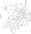
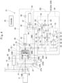
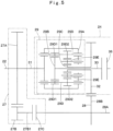
- the planetary gear mechanism 29 is provided with two sun gears 29B, 29C, a planet gear 29D and a balance gear 29E revolving about a center axis S ( Fig. 6 ) of the two sun gears 29B, 29C and rotating on its own axis, and one carrier 29A supporting the planet gear 29D and the balance gear 29E to be capable of rotating about the center axis S of the two sun gears 29B, 29C.
- the planetary gear mechanism 29 can be provided with a gear arrangement in which a gear ratio becomes an optimal value.
- the speed-changing device 21 according to the first embodiment.
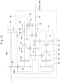
- the planetary gear mechanism 29 in the speed-changing device 21 is shown in a box, and on the other hand, Fig. 4 shows an internal part of the planetary gear mechanism 29, that is, also a specific gear arrangement of the planetary gear mechanism 29.
- Fig. 3 and Fig. 4 are configuration diagrams of the speed-changing device 21 according to the first embodiment, more specifically the speed-changing device 21 provided with both of the internal lockup and the external lockup.
- the speed-changing device 21 is provided with the input shaft 22 as an input member, the output shaft 23 as an output member, the planetary stepless speed-changing mechanism 24 as a stepless speed-changing mechanism (main speed-changing mechanism), and a controller 25.
- the speed-changing device 21 is provided with a multistage speed-changing mechanism 26 as a stepped speed-changing mechanism (sub speed-changing mechanism), and a direct connecting mechanism 27 as an external lockup mechanism.
- the direct connecting mechanism 27 is provided with a first clutch 27C to be connected at the time of transmitting the power through the direct connecting mechanism 27.
- the speed-changing device 21 is provided with an idler element 28 (an idler shaft 28A and an idler gear 28B) that mechanically connects the planetary stepless speed-changing mechanism 24, the multistage speed-changing mechanism 26 and the direct connecting mechanism 27 .
- the planetary stepless speed-changing mechanism 24 configures a first power transmission route.
- the direct connecting mechanism 27 configures a second power transmission route.
- the engine 9 is connected to the input shaft 22 of the speed-changing device 21 .
- the input shaft 22 is provided with the gear 10B for transmitting the power to the hydraulic pump 10.
- the input shaft 22 is provided with an input gear 27A of the direct connecting mechanism 27.
- the input shaft 22 is connected via a second connecting member 31 to be described later to the planetary stepless speed-changing mechanism 24 (more specifically, the planetary gear mechanism 29).
- the power is outputted from the output shaft 23 of the speed-changing device 21 .
- the output shaft 23 of the speed-changing device 21 acts also as an output shaft 53 of the multistage speed-changing mechanism 26 to be described later.
- the power inputted from the input shaft 22 is transmitted via the planetary stepless speed-changing mechanism 24 or the direct connecting mechanism 27 to the idler element 28 .
- the power transmitted to the idler element 28 is outputted through the multistage speed-changing mechanism 26 from the output shaft 23 .
- the planetary stepless speed-changing mechanism 24 forms a state of the internal lockup by stopping a first connecting member 30 for connecting the planetary gear mechanism 29 (for example, a first sun gear 29B) and the first variator 33 .
- the state of the internal lockup is formed, for example, by braking the first variator 33 to stop the first connecting member 30.
- the power transmission route for transmitting the power inputted from the engine 9 to the input shaft 22 to the multistage speed-changing mechanism 26 can be selected from any one of three routes of the following (A), (B) and (C).
- steplessly speed-change the planetary stepless speed-changing mechanism 24 it is possible to perform the power transmission by steplessly speed-changing the planetary stepless speed-changing mechanism 24.
- the power transmission can be performed via the direct connecting mechanism 27.
- the vehicle is at the excavating or at the transporting and the vehicle speed is in a range of 0 to 7km/h. This reason is shown as the following (a) to (c).
- the vehicle At the time it is appropriate to perform the power transmission by making the planetary stepless speed-changing mechanism 24 operate in the internal lockup, the vehicle is at the transporting or at the deadheading and the vehicle speed is in a range of 7 to 9km/h. This reason is shown as the following (d) and (e).
- the vehicle At the time it is appropriate to perform the transmission of the power via the direct connecting mechanism 27, the vehicle is at the transporting and the vehicle speed is in a range of 9 to 13km/h. In addition, the vehicle is at the deadheading and the vehicle speed is in a range of 9 to 40km/h. This reason is as follows.
- the transmission efficiency of the power is the highest. That is, since the power is transmitted in the external lockup by meshing of a pair of gears 27A, 27B each other, the transmission efficiency is higher than in the internal lockup of performing the power transmission via the planetary gear mechanism 29.
- Table 1 shows a combination of power transmission routes in the speed-changing device 21 provided with both of the internal lockup and the external lockup.
- the multistage speed-changing mechanism 26 is provided with a shift stage of a forward four-speed and a backward one-speed. Therefore, in a case of performing the power transmission via the direct connecting mechanism 27 (external lockup mechanism), the multistage speed-changing mechanism 26 can select a shift stage of a forward one-speed, a forward two-speed, a forward three-speed, a forward four-speed and a backward one-speed.
- the power transmission may be performed via the planetary stepless speed-changing mechanism 24 without via the direct connecting mechanism 27.
- the operation of the planetary stepless speed-changing mechanism 24 at this time may be a stepless speed-changing operation or in a state of being in the internal lockup.
- the transmission efficiency of the planetary stepless speed-changing mechanism 24 is lower than in the internal lockup and the external lockup. Thereby, since the transmission efficiency of the speed-changing device 21 is lower, favorably it is preferable to select a combination of power transmission routes as shown in Table 1.
- Fig. 12 shows a drive force diagram of the speed-changing device 21 in which the internal lockup and the external lockup both are present.
- the speed change is made possible in six stages of a forward one-speed stepless speed change Lf1, a forward one-speed internal lockup Lf2, a forward one-speed external lockup Lf3, a forward two-speed external lockup Lf4, a forward three-speed external lockup Lf5 and a forward four-speed external lockup Lf6.
- the drive force diagram can be made as close as possible to the idealistic drive force line Lf in the forward direction.
- the speed change is made possible in three stages of a backward one-speed stepless speed change Lr1, a backward one-speed internal lockup Lr2 and a backward one-speed external lockup Lr3.
- the drive force diagram can be made as close as possible to the idealistic drive force line Lr in the backward direction.
- a high traction force can be obtained at the excavating, and a high vehicle speed (0 to 40km/h) can be obtained at the deadheading.
- the wheel loader 1 stably travels on the upslopes at various grades.
- the speed-changing device 21 is provided with both of “the internal lockup of the planetary stepless speed-changing mechanism 24" and “the external lockup by the direct connecting mechanism 27".
- the speed-changing device 21 may be provided with only one of the internal lockup and the external lockup.
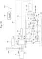
- Fig. 13 shows a speed-changing device 21A according to a first modification example provided with only the internal lockup of the planetary stepless speed-changing mechanism 24 as a device for realizing the lockup.
- the internal lockup operation of the planetary stepless speed-changing mechanism 24 is made possible but an external lockup mechanism (direct connecting mechanism 27) is not provided.
- Table 2 as follows shows a combination of power transmission routes of the speed-changing device 21A provided with the internal lockup only.
- a multistage speed-changing mechanism 26A is provided with speed shift stages of forward five stages and backward two stages in the first modification example.
- the planetary stepless speed-changing mechanism 24 is provided with a block mechanism 40 for realizing the internal lockup as to be described later in the first modification example.
- Fig. 14 shows a speed-changing device 21B according to a second modification example.
- the speed-changing device 21B according to the second modification example also omits the external lockup mechanism as to be similar to the first modification example.
- the controller 25 is configured of a microcomputer provided with, for example, a calculation circuit (CPU), a memory and the like.
- the controller 25 controls engagement and disengagement of the first clutch 27C, engagement and disengagement of the second clutch 36 and engagement and disengagement of the third clutch 37.
- the controller 25 controls a rotation speed of the first variator 33.
- the controller 25 controls a rotation speed of the second variator 34 as needed.
- the controller 25 controls the transmission element 35 and the power storage source 38 as needed.
- the controller 25 controls the block mechanism 40 ( Fig. 13 ) and the brake mechanism 41 ( Fig. 14 and Fig. 15 ) to be described later, as needed.
- the controller 25 controls engagement and disengagement of clutches 58, 59, 60, 66, 67, 68, 69 in the multistage speed-changing mechanism 26 to be described later.
- the controller 25 controls the engagement and disengagement of the second clutch 36. For example, when the power transmission by the planetary stepless speed-changing mechanism 24 is unnecessary, the controller 25 outputs a signal for disengaging the second clutch 36 to disengage the second clutch 36. Thereby, the rotation of the first variator 33 can be stopped (or reduced) to reduce power loss due to the rotation of the first variator 33.
- the third clutch 37 is configured of, for example, a clutch (friction plates) by friction joint, a dog clutch or a dog clutch with synchromesh.
- the third clutch 37 performs mechanical engagement (connection) and disengagement of the second variator 34 and the idler element 28 therebetween.
- the controller 25 controls the engagement and disengagement of the third clutch 37. For example, when the power transmission by the second variator 34 is unnecessary, the controller 25 outputs a signal for disengaging the third clutch 37 to disengage the third clutch 37. Thereby, the rotation of the second variator 34 can be stopped (or reduced) to reduce power loss due to the rotation of the second variator 34 .
- the third clutch 37 is not necessarily disengaged under these conditions.
- No.1-A in Table 4 is the most preferable from a viewpoint of improving the transmission efficiency of the planetary stepless speed-changing mechanism 24 and configuring the planetary gear mechanism 29 in a small size and a light weight.
- Table 4 No. First member linked to power source Second member linked to first variator Third member linked to idler element Number of Figure 1-A carrier first sun gear second sun gear Fig. 4 (first embodiment) Fig. 20 (sixth modification example) 1-B first sun gear carrier second sun gear Fig. 18 (fourth modification example) 1-C first sun gear second sun gear carrier Fig. 19 (fifth modification example)
- the planetary gear mechanism 29 is provided with the carrier 29A corresponding to a first member, the first sun gear 29B corresponding to a second member, the second sun gear 29C corresponding to a third member, a planet gear 29D and a balance gear 29E.
- the first sun gear 29B, the second sun gear 29C, the planet gear 29D and the balance gear 29E may not perform the power transmission by the meshing of gears but may perform the power transmission by friction of a roller (an outer peripheral surface thereof), for example.
- Fig. 6 is a cross section showing the planetary gear mechanism 29 as viewed from the power source side.
- the carrier 29A, the first sun gear 29B and the second sun gear 29C are concentrically arranged. That is, the center axis S (rotation center axis) of each of the carrier 29A, the first sun gear 29B and the second sun gear 29C is in agreement.
- the first sun gear 29B is meshed with the gear part 29D1 of the planet gear 29D.
- the second sun gear 29C is meshed with the balance gear 29E.
- the balance gear 29E is meshed with the gear part 29D2 of the planet gear 29D.
- the balance gear 29E and the planet gear 29D rotate freely in a rotating direction by the carrier 29A and are restricted in a revolving direction in relation to the center axis S in such a way that each meshing of the gears establishes. Therefore, the planet gear 29D rotates about the rotating axis Sp as the center axis of the planet gear 29D and revolves about the center axis S of the carrier 29A. Therefore, a trace Cp of the center axis (rotating axis Sp) of the planet gear 29D becomes a circle about the center axis S of the carrier 29A.
- the balance gear 29E rotates about the rotating axis Sb as the center axis of the balance gear 29E and revolves about the center axis S of the carrier 29A. Therefore, a trace Cb of the center axis (rotating axis Sb) of the balance gear 29E becomes a circle about the center axis S of the carrier 29A.
- torque Tc of the carrier 29A is a torque that the engine 9 can generate.
- first sun gear 29B is connected to a member linked to the first variator 33, that is, the first connecting member 30
- torque Ts1 of the first sun gear 29B is a torque that the first variator 33 can generate.
- second sun gear 29C is connected to a member linked to the idler element 28, that is, the third connecting member 32
- torque Ts2 of the second sun gear 29C is a torque reaction that receives from the idler element 28.
- the controller 25 outputs a signal for controlling the first variator 33 based upon this principle, and controls the torque of the first connecting member 30 (for example, the first sun gear 29B) linked to the first variator 33. That is, the controller 25 controls the torque of the first connecting member 30 (for example, the first sun gear 29B) by controlling the first variator 33. Thereby, the controller 25 indirectly controls the torque of the second connecting member 31 (for example, the carrier 29A) linked to the engine 9 and the torque of the third connecting member 32 (for example, the second sun gear 29C) linked to the idler element 28. As a result, the transmission torque can be controlled between the second connecting member 31 (for example, the carrier 29A) linked to the engine 9 and the third connecting member 32 (for example, the second sun gear 29C) linked to the idler element 28.
- Vc The rotating speed of the carrier 29A
- Vs1 the rotating speed of the first sun gear 29B
- Vs2 the rotating speed of the second sun gear 29C
- Vs 2 ⁇ Ka Vs 1 Vc + Ka + 1
- Ka rs 1 ⁇ rp 2 rs 2 ⁇ rp 1
- the planetary gear mechanism 29 adjusts the mesh radius rs1 of the first sun gear 29B, the mesh radius rp1 of the gear part 29D1, the mesh radius rs2 of the second sun gear 29C and the mesh radius rp2 of the gear part 29D2 in accordance with the torque that can be absorbed by the first variator 33 and an allowable maximum rotation speed thereof from the relation formulas (Formula 2, Formula 3 and Formula 4) of the torques Tc, Ts1 and Ts2 and from the relation formulas (Formula 5 and Formula 6) of the rotating speeds Vs1, Vs2 and Vc.
- the torque and the rotation speed of the planetary gear mechanism 29 can be adapted to both of the torque that can be absorbed by the first variator 33 and the allowable maximum rotation speed thereof.
- the first variator 33 that is small-sized and inexpensive can be used to improve the transmission efficiency of the planetary stepless speed-changing mechanism 24.
- the rotation speed of the first sun gear/the rotation speed of the carrier becomes 3.0.
- the value of Ka is preferably made small within a range not exceeding the allowable maximum rotation speed of the first variator 33.
- the value of Ka can freely be determined. Therefore, the vehicle can drive to the allowable maximum rotation speed of the first variator 33. As a result, it is possible to use the first variator 33 that is small-sized and inexpensive and improve the transmission efficiency of the planetary stepless speed-changing mechanism 24 to 80% to 93%.
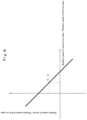
- Formula 7 as follows is derivable by modifying Formula 5.
- a diagrammatic drawing in Formula 7 is shown in Fig. 8 .
- Vc Vs 1 1 Ka + 1 Vs 2 Vs 1 + ka Ka + 1
- Ka 3. That is, the upper limit value of Ka in this case becomes a value between before and after 3. Therefore, the value of Ka is preferably made large within a range not exceeding the allowable maximum rotation speed of the first variator 33. In addition, as described above since it is possible to freely determine the value of Ka, the vehicle can drive to the allowable maximum rotation speed of the first variator 33. As a result, it is possible to use the first variator 33 that is small-sized and inexpensive and improve the transmission efficiency of the planetary stepless speed-changing mechanism 24 to 80% to 93%.
- the second sun gear 29C is connected via the idler element 28 and the multistage speed-changing mechanism 26 to the output shaft 23, in a case of rotating in Vs2 of a high rotation, a vehicle travels in a higher vehicle speed. Since a range of a speed change of the planetary stepless speed-changing mechanism 24 is the wider the better, the maximum value of "Vs2/Vs1" is preferably the larger. However, the allowable rotation speed (Vs2) of the third connecting member 32 linked to the idler element 28 is approximately 8000min -1 .
- the vehicle can drive to the allowable maximum rotation speed of the first connecting member 30 linked to the first variator 33.
- the transmission torque of the first variator 33 is made small and it is possible to use the first variator 33 that is small-sized and inexpensive.
- the power transmission efficiency of the planetary stepless speed-changing mechanism 24 is 80% to 93%, which is high as a stepless transmission.
- the power transmission efficiency of a gear transmission by the meshing of a pair of gears each other is approximately 99%. Therefore, the planetary stepless speed-changing mechanism 24 is lower in a power transmission efficiency than a transmission by the meshing of a pair of gears each other. This reason will be explained with reference to Fig. 3 .
- a transmission efficiency of power between the planetary gear mechanism 29 and the idler element 28 (idler gear 28B) will be considered.
- the transmission efficiency of the power transmission route via the first connecting member 30, the first variator 33, the transmission element 35, the second variator 34, the transmission 39 and the third clutch 37 is approximately 70% to 80%.
- the transmission efficiency of the power transmission route via the third connecting member 32 is approximately 99%. Therefore, for enhancing the transmission efficiency, the rotation of the first connecting member 30 linked to the first variator 33 has only to be stopped, not performing the power transmission between the first variator 33 and the second variator 34.
- the power is transmitted to the third connecting member 32 and the idler gear 28B by the meshing of the gears each other, the power supplied from the engine 9 through the second connecting member 31 to the planetary gear mechanism 29 can be transmitted to the idler gear 28B in a high efficiency.
- the power transmission efficiency of the planetary stepless speed-changing mechanism 24 is improved to approximately 97%, making it possible to improve the transmission efficiency of the speed-changing device 21.
- the wheel loader 1 can be configured to perform fuel saving.
- the planetary stepless speed-changing mechanism 24 operates in a fixed speed change ratio.
- the internal lockup speed change ratio In depends upon a combination of gears in the planetary gear mechanism 29, and Ka.
- the rotation of the first connecting member 30 linked to the first variator 33 of the three connecting members 30, 31, 32 linked to the planetary gear mechanism 29 has only to be stopped.
- the controller 25 holds a volume of the hydraulic pump/motor of the first variator 33 to a predetermined value or more (preferably 10% or more of the maximum volume) and controls a volume of the hydraulic pump/motor of the second variator 34 to 0.
- the block mechanism 40 which is configured to be disposed in the transmission element 35 performing the power transmission between the first variator 33 and the second variator 34, may be adopted.
- the block mechanism 40 is controlled by the controller 25 to block the power transmission between the first variator 33 and the second variator 34.
- the block mechanism 40 may be configured of a hydraulic valve.
- the controller 25 sends a signal to the block mechanism 40 to block the flow of oil between the first variator 33 and the second variator 34.
- the block mechanism 40 may be configured by an inverter/converter. In this case, the inverter/converter gives a quasi-resistance between power lines to increase a voltage between the power lines.
- the block mechanism 40 may be configured to block the flow of power by a magnet contactor or may be configured to give a resistance between power lines by a resistor.
- the controller 25 sends a signal of transmission or blockade of power to the block mechanism 40 to control the block mechanism 40.
- the internal lockup state may be realized by fixing the rotation shaft of the first variator 33 to a non-rotation part to stop the rotation of the first variator 33.
- the internal lockup state may be realized by fixing the first connecting member 30 to a non-rotation part (for example, a case of the speed-changing device 21) by the brake mechanism 41.
- the brake mechanism 41 may adopt the configuration of fixing the first connecting member 30 linked to the first variator 33 to the non-rotation part by friction joint or mechanical meshing joint.
- the first variator 33 is an electric generator
- even at the operating of the internal lockup it is necessary to make current flow in the first variator 33 (electric generator). Therefore, from a point of view of power loss, it is preferable to fix the first connecting member 30 to the non-rotation part by the brake mechanism 41. That is, in a case where the first variator 33 is the electric generator, from a point of view of power loss, it is preferable to fix the first connecting member 30 to the non-rotation part by the brake mechanism 41.
- the power transmission of the planetary stepless speed-changing mechanism 24 at the internal lockup time can improve to configure the wheel loader 1 to perform fuel saving.
- the speed-changing devices 21A, 21B and 21C according to the first to third modification examples as shown in Fig. 13 to Fig. 15 can perform the internal lockup operation of the planetary stepless speed-changing mechanism 24 but are not provided with the external lockup mechanism (direct connecting mechanism 27).
- the speed-changing devices 21A, 21B and 21C of this type at the starting-up and at the excavating, the planetary stepless speed-changing mechanism 24 is steplessly changed in a speed to perform the power transmission, and at the transporting and at the deadheading, the planetary stepless speed-changing mechanism 24 is made to operate in the internal lockup to perform the power transmission.
- the power transmission efficiency can be enhanced by the stepless speed change of the planetary stepless speed-changing mechanism 24.
- the power transmission efficiency can be further enhanced by making the planetary stepless speed-changing mechanism 24 operate in the internal lockup than the stepless speed change.
- the wheel loader 1 can be configured to perform fuel saving.
- the direct connecting mechanism 27 transmits the power supplied from the engine 9 to the idler gear 28B by the meshing of a pair of gears each other without via the planetary stepless speed-changing mechanism 24. Since the power transmission efficiency of the direct connecting mechanism 27 is approximately 99%, the power transmission efficiency of the speed-changing device 21 improves, making it possible to configure the wheel loader 1 to perform fuel saving.
- the direct connecting mechanism 27 is provided with the input gear 27A disposed in the input shaft 22, a lockup gear 27B meshing with the input gear 27A, and the first clutch 27C.
- a rotation shaft 27B1 in which the lockup gear 27B is disposed is connected via the first clutch 27C to the idler shaft 28A of the idler element 28.
- the first clutch 27C is configured of, for example, a clutch (friction plates) by friction joint, a dog clutch or a dog clutch with synchromesh.
- the first clutch 27C performs mechanical engagement (connection) and disengagement between the lockup gear 27B and the idler gear 28B.
- the second clutch 36 is disengaged and the first clutch 27C is engaged, whereby the power inputted from the input shaft 22 is transmitted via the input gear 27A, the lockup gear 27B and the first clutch 27C to the idler gear 28B.
- the power supplied from the engine 9 is transmitted via the direct connecting mechanism 27 as the external lockup mechanism without via the planetary stepless speed-changing mechanism 24 to the idler gear 28B.
- the planetary stepless speed-changing mechanism 24 can increase a speed of the third connecting member 32 linked to the idler gear 28B in relation to the second connecting member 31 linked to the power source (engine 9) according to characteristics of the planetary gear mechanism 29 in the speed relation line Y1 as shown in Fig. 7 .
- the multistage speed-changing mechanism 26 For transmitting the power inputted to the idler gear 28B to the output shaft 53 with a forward one-speed, the fourth clutch 58 is engaged, the fifth clutch 66 is disengaged, the sixth clutch 59 is engaged, and the eighth clutch 60 is disengaged. In this state, two clutches or more of the seventh clutch 67, the tenth clutch 68 and the nineth clutch 69 are disengaged.
- the forward one-speed corresponds to No.1 to No.4 in Table 5 to be described later.
- the fifth clutch 66 and the tenth clutch 68 are engaged, and the fourth clutch 58, the seventh clutch 67 and the nineth clutch 69 are disengaged. In this state, one or both of the sixth clutch 59 and the eighth clutch 60 are disengaged.
- the forward four-speed corresponds to No.12 to No.14 in Table 5 to be described later.
- the fifth clutch 66 and the nineth clutch 69 are engaged, and the fourth clutch 58, the seventh clutch 67 and the tenth clutch 68 are disengaged. In this state, one or both of the sixth clutch 59 and the eighth clutch 60 are disengaged.
- the backward one-speed corresponds to No.15 to No.17 in Table 5 to be described later.
- any one of the forward two-speed gear 63, the forward four-speed gear 64 or the backward one-speed gear 65 can be in advance engaged to the even numbered stage shaft 70.
- the switching between the engagement and the disengagement of the sixth clutch 59 and the eighth clutch 60 it is possible to perform the switching between the engagement and the disengagement of the sixth clutch 59 and the eighth clutch 60.
- any one of the forward one-speed gear 56 or the forward three-speed gear 57 can be in advance engaged to the odd numbered stage shaft 61.
- the power transmission from the idler gear 28B to the output shaft 53 can be switched from via the odd numbered stage shaft 61 to via the even numbered stage shaft 70 by changing a state where the fourth clutch 58 is engaged and the fifth clutch 66 is disengaged to a state where the fourth clutch 58 is disengaged and the fifth clutch 66 is engaged.
- the power transmission from the idler gear 28B to the output shaft 53 can be switched from via the even numbered stage shaft 70 to via the odd numbered stage shaft 61 by changing a state where the fourth clutch 58 is disengaged and the fifth clutch 66 is engaged to a state where the fourth clutch 58 is engaged and the fifth clutch 66 is disengaged.
- the switching in the engagement of the fourth clutch 58 and the fifth clutch 66 is not necessarily performed alternately.
- Table 5 as follows, there are the switching from No.1 to 4 to No.5 to 8 and the switching from No.5 to 8 to No.1 to 4.
- the sixth clutch 59 and the eighth clutch 60 are engaged or disengaged. After that, the disengaged fourth clutch 58 is engaged.
- the planetary stepless speed-changing mechanism 24 can reverse the rotation direction of the third connecting member 32 linked to the idler gear 28B by controlling the rotation speed of the first connecting member 30 linked to the first variator 33 based upon the speed relation line Y1 of the planetary gear mechanism 29 as shown in Fig. 7 .
- the first variator 33 connected to the first connecting member 30 is required to adopt a variator higher in the limitation of the maximum rotation speed. Therefore, the first connecting member 30 linked to the first variator 33 is rotated in a high speed and the rotation direction of the third connecting member 32 linked to the idler gear 28B is reversed from a normal rotation, resulting in adoption of the first variator 33 that is expensive and is high in the maximum rotation speed. Thereby, a cost price of the planetary stepless speed-changing mechanism 24 possibly increases. Therefore, when the wheel loader 1 travels backward, it is preferable to reverse the rotation direction of the output shaft 53 (output shaft 23) from the forward direction to the backward direction by using the multistage speed-changing mechanism 26.
- the first embodiment that is, No.1-A in Table 4
- the fourth modification example that is, No.1-B in Table 4
- the fifth modification example that is, No.1-C in Table 4
- the speed-changing device 21 is provided with the input shaft 22 (input member) linked to the power source (engine 9), the output shaft 23 (output member) linked to the load (the front axle 12 and the rear axle 13), the planetary gear mechanism 29 (planetary mechanism) disposed between the input shaft 22 and the output shaft 23, the first variator 33 connected to the planetary gear mechanism 29, the second variator 34 disposed apart from the first variator 33 and the controller 25 configured to change the rotation speed of the first variator 33.
- the planetary gear mechanism 29 is configured to include three members (rotation members) of the carrier 29A, the first sun gear 29B (first sun member) rotating about the rotation center axis of the carrier 29A and the second sun gear 29C (second sun member) rotating about the rotation center axis of the carrier 29A.
- the carrier 29A as the first member that is one of the three members is connected via the second connecting member 31 (the other member) to the input shaft 22.
- the first sun gear 29B as the second member apart from the carrier 29A is connected via the first connecting member 30 and the second clutch 36 (any of them is the other member) to the first variator 33.
- the second sun gear 29C as the third member apart from the carrier 29A and the first sun gear 29B is connected via the third connecting member 32, the idler element 28 and the multistage speed-changing mechanism 26 (any of them is the other member) to the output shaft 23.
- the carrier 29A (first member) may be connected directly to the input shaft 22.
- the first sun gear 29B (second member) may be connected directly to the first variator 33.
- the second sun gear 29C (third member) may be connected directly to the output shaft 23.
- the planet gear 29D (planet member) and the balance gear 29E (balance member) as the counter gear are supported on the carrier 29A, the planet gear 29D and the balance gear 29E performing the power transmission while revolving about the rotation center axis S of the carrier 29A and rotating with the first sun gear 29B and the second sun gear 29C.
- the planetary gear mechanism 29 distributes the torque transmitted to the carrier 29A (first member) of the planetary gear mechanism 29 from the engine 9 to the first sun gear 29B (second member) and the second sun gear 29C (third member).
- the planetary gear mechanism 29 performs the rotation motion with two degrees of freedom between the carrier 29A, the first sun gear 29B and the second sun gear 29C.
- the second variator 34 transmits the power transmitted from the first variator 33 to the load (output shaft 23) or the power source (input shaft 22), or transmits the power transmitted from the load (output shaft 23) or the power source (input shaft 22) to the first variator 33.
- the controller 25 changes the rotation speed of the first variator 33 to change the rotation speed of the output shaft 23 in relation to the rotation speed of the input shaft 22.
- the speed-changing device 21 in the first embodiment performs the speed change steplessly by the planetary gear mechanism 29 and transmits the power transmitted from the power source (input shaft 22) to the load (output shaft 23) or transmits the power transmitted from the load (output shaft 23) to the power source (input shaft 22).
- the speed-changing device 21 is provided with the planetary gear mechanism 29 disposed between the input shaft 22 and the output shaft 23, the first variator 33 connected to the planetary gear mechanism 29, and the second variator 34 transmitting the power transmitted from the first variator 33 to the load or the power source.
- the planetary gear mechanism 29 is provided with the carrier 29A that is connected to the input shaft 22 and on which the planet gear 29D and the balance gear 29E are supported, the first sun gear 29B connected to the first variator 33, and the second sun gear 29C connected via the idler element 28 and the multistage speed-changing mechanism 26 to the output shaft 23. Further, the speed-changing device 21 is provided with at least one lockup of the internal lockup and the external lockup (direct connecting mechanism 27). The speed-changing device 21 can perform the switching between the power transmission by the planetary stepless speed-changing mechanism 24 and the power transmission by the lockup.
- the speed-changing device 21 high in the transmission efficiency can be provided to reduce the power loss of the wheel loader 1 as the working vehicle.
- a change in an acceleration/deceleration speed of a vehicle can be made small.
- the gear arrangement in which a gear ratio of the planetary gear mechanism 29 becomes an optimal value can be provided to improve the transmission efficiency of the planetary stepless speed-changing mechanism 24. That is, even in a case of using the first variator 33 that is inexpensive and is small-sized and in which the upper limit value in the rotation speed and the upper limit value in the generation (absorption) possible torque are limited, the transmission efficiency of the planetary stepless speed-changing mechanism 24 can be improved.
- the power transmission by the lockup mechanism is performed. Therefore, in this case it is possible to perform the power transmission (the internal lockup and the external lockup) by the meshing of gears each other high in the transmission efficiency.
- the power transmission by the planetary stepless speed-changing mechanism 24 is performed. Therefore, the stepless speed change can be made by operating the planetary stepless speed-changing mechanism 24.
- the power transmission by the planetary stepless speed-changing mechanism 24 is possibly made lower in a transmission efficiency than the power transmission (the internal lockup and the external lockup) to be performed only by the meshing of gears each other.
- the stepless speed change by the planetary stepless speed-changing mechanism 24 can be made higher in a transmission efficiency than the stepless speed change by a torque converter.
- the operation speed of the cargo working machine 7 can be suppressed from rapidly changing to improve the operability of the cargo working machine 7.
- the power loss by the distribution can be reduced.
- the controller 25 stops the rotation of the first sun gear 29B (second member) in the planetary gear mechanism 29 to realize the state of the internal lockup. That is, the controller 25 stops the rotation of the first sun gear 29B to change a state of performing the rotation motion with two degrees of freedom between the carrier 29A, the first sun gear 29B and the second sun gear 29C to a state of performing the rotation motion with one degree of freedom.
- the planetary gear mechanism 29 transmits the power transmitted from the power source to the planetary gear mechanism 29 to the load in a state of being in one degree of freedom.
- the controller 25 outputs a command of making the rotation speed be 0 to the first variator 33.
- the controller 25 outputs a command of stopping the rotation of the member to be connected to the first variator 33 by a mechanical engagement.
- the controller 25 outputs a command of blocking the power to be sent to the second variator 34 from the first variator 33. Thereby, the controller 25 stops the rotation of the first sun gear 29B.
- the internal lockup can be realized by stopping the rotation of the first sun gear 29B in the planetary gear mechanism 29 to improve the transmission efficiency.
- the speed-changing device 21 is provided with two power transmission routes composed of a first power transmission route (planetary stepless speed-changing mechanism 24) and a second power transmission route (direct connecting mechanism 27). That is, the power transmission route for transmitting the power from the power source through the planetary gear mechanism 29 to the load (output shaft 23) is defined as the first power transmission route.
- the second power transmission route is disposed in the speed-changing device 21 to be in parallel with the first power transmission route.
- the second power transmission route is the direct connecting mechanism 27 (external lockup mechanism) for transmitting the power to the load (output shaft 23) by the meshing of gears each other without via the planetary gear mechanism 29 .
- the second power transmission route (the direct connecting mechanism 27) is provided with the first clutch 27C for switching the engagement and the disengagement.
- the controller 25 engages the first clutch 27C and performs the power transmission through the second power transmission route (direct connecting mechanism 27). Thereby, the transmission efficiency can improve more than the configuration of performing the internal lockup only, for example.
- the speed ratio when the rotation speed of the carrier 29A (first member) is the same as that of the second sun gear 29C (third member) is defined as a synchronization rotation speed ratio.
- a value is found by dividing the rotation speed of the second sun gear 29C (third member), at the time the power transmission is performed via the second transmission route (direct connecting mechanism 27) by engaging the first clutch 27C, by the rotation speed of the power source. That value is defined as a lockup rotation speed ratio.
- the lockup rotation speed ratio is larger than the synchronization rotation speed ratio. Therefore, at the time of transmitting the power through the second power transmission route as the external lockup mechanism, the speed can increase.
- the second clutch 36 is disposed between the first sun gear 29B (second member) and the first variator 33 to switch the transmission and release in power between the first sun gear 29B (second member) and the first variator 33.
- the controller 25 disconnects the power transmission between the first sun gear 29B (second member) and the first variator 33 by disengaging the second clutch 36 during the time the working vehicle (wheel loader 1) is stopped. As a result, when a vehicle speed of the wheel loader 1 is 0, the power transmission to the first variator 33 can be blocked.
- the controller 25 engages the second clutch 36 for stopping the first sun gear 29B (second member). Therefore, at the internal lockup it is possible to stop the rotation of the first sun gear 29B (second member).
- the third clutch 37 is disposed between the second variator 34 and the load or the power source to switch the transmission and release in power between the second variator 34 and the load or the power source. The controller 25 disengages the third clutch 37 during the time the first sun gear 29B (second member) is stopped. Therefore, at the internal lockup it is possible to block the power transmission to the second variator 34. It should be noted that at the internal lockup the second clutch 36 is required to be engaged, but the third clutch 37 can be either disengaged or engaged.
- the controller 25 disengages the second clutch 36 during the time the first clutch 27C is engaged. Therefore, at the external lockup it is possible to block the power transmission to the first variator 33.
- the controller 25 disengages the third clutch 37 during the time the first clutch 27C is engaged. Therefore, at the external lockup it is possible to block the power transmission to the second variator 34. It should be noted that at the external lockup the second clutch 36 and the third clutch 37 can be either disengaged or engaged.
- the multistage speed-changing mechanism 26 is disposed between the second sun gear 29C (third member) and the output shaft 23 (output member).
- the multistage speed-changing mechanism 26 is provided with the first output transmission route (odd numbered shaft 51) and the second output transmission route (even numbered shaft 52).
- the number of times of the gear meshing is the odd number of times between the second sun gear 29C (third member) and the output shaft 23 (output member).
- the number of times of the gear meshing may be the odd number of times or the even number of times between the second sun gear 29C (third member) and the output shaft 23 (output member).
- a route, for transmitting the power from the idler gear 28B via the even numbered stage gear 62, the fifth clutch 66, the nineth clutch 69, the counter gear 54 and the backward one-speed output gear 75 to the output shaft 53, of the second output transmission route (even numbered shaft 52) has the number of times of the gear meshing as the even number of times.
- the number of times of the gear meshing between the second sun gear 29C (third member) and the output shaft 23 (output member) by the other route becomes the odd number of times.
- the first output transmission route (odd numbered shaft 51) is provided with a first output clutch (the fourth clutch 58, sixth clutch 59 and eighth clutch 60) for switching the transmission and release of power in the first output transmission route.
- the second output transmission route (even numbered shaft 52) is provided with a second output clutch (the fifth clutch 66, seventh clutch 67, tenth clutch 68 and nineth clutch 69) for switching the transmission and release of power in the second output transmission route.
- the controller 25 switches a normal rotation mode and a reverse rotation mode, in the normal rotation mode (for example, in a one-speed mode) the first output clutch (the fourth clutch 58 and sixth clutch 59) being engaged and the second output clutch (for example, the fifth clutch 66) being disengaged and in the reverse rotation mode (backward mode) the first output clutch (for example, the fourth clutch 58) being disengaged and the second output clutch (for example, the fifth clutch 66 and nineth clutch 69) being engaged.
- a forward direction of the wheel loader 1 (vehicle) is reversed by this switching. Therefore, the speed-changing device 21 can reverse the rotation direction of the load (output shaft 23).
- the speed-changing device 21 is provided with the multistage speed-changing mechanism 26 as a sub speeding-changing mechanism.
- the second variator 34 is connected to an idler element (specifically, the idler gear 28B as a rotation element) disposed between the planetary gear mechanism 29 and the multistage speed-changing mechanism 26.
- the second variator 34 may be connected to the output shaft 23 (output member). That is, as shown in Fig. 30 to Fig.
- the second variator 34 may be configured to be connected to a rotation element disposed between the input shaft 22 (input member) and the drive source (engine 9), a rotation element configuring the multistage speed-changing mechanism 26, a rotation element disposed between the multistage speed-changing mechanism 26 and the output shaft 23 (output member), the output shaft 23 (output member), or a rotation element disposed between the output shaft 23 and the load.
- Fig. 21 to Fig. 24 show a second embodiment.
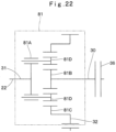
- the second embodiment is characterized in that a planetary gear mechanism is configured of a carrier, a sun gear and a ring gear. It should be noted that in the second embodiment, components identical to those in the first embodiment are referred to as the identical reference numerals, and an explanation thereof is omitted.
- the explanation is made by taking as an example a case where the planetary gear mechanism 29 in the planetary stepless speed-changing mechanism 24 is configured of the carrier and the two sun gears.
- a planetary gear mechanism 81 in the planetary stepless speed-changing mechanism 24 is configured of a carrier 81A, a sun gear 81B and a ring gear 81C.
- Table 6 shows a combination of configuration elements (a carrier, sun gear and ring gear) of the planetary gear mechanism 81. In any case, the power transmission is made possible.
- No.2-A in Table 6 is the most preferable from a point of view that the transmission efficiency of the planetary stepless speed-changing mechanism 24 can improve, the maximum absorption torque of the first variator 33 can be made small, and the entirety of the planetary stepless speed-changing mechanism 24 can be configured to be small-sized and light in weight.
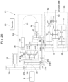
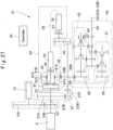
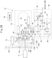
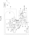
- Table 6 No. First member linked to power source Second member linked to first variator Third member linked to idler element Number of Figure 2-A carrier sun gear ring gear Fig. 21 (second embodiment) 2-B ring gear carrier sun gear Fig. 25 (seventh modification example) 2-C carrier ring gear sun gear Fig. 26 (eighth modification example) 2-D ring gear sun gear carrier Fig. 27 (nineth modification example) 2-E sun gear ring gear carrier Fig. 28 (tenth modification example) 2-F sun gear carrier ring gear Fig. 29 (eleventh modification example)
- the planetary gear mechanism 81 is provided with the carrier 81A corresponding to a first member, the sun gear 81B corresponding to a second member, the ring gear 81C corresponding to a third member and the planet gear 81D.
- the power transmission of the sun gear 81B, the ring gear 81C and the planet gear 81D may be performed not by the meshing of gears but by friction of a roller (an outer peripheral surface), for example.
- the engine 9 is connected via the second connecting member 31 to the carrier 81A.
- the sun gear 81B is connected via the first connecting member 30 to the first variator 33.
- the ring gear 81C is connected via the third connecting member 32 to the idler element 28 (idler gear 28B).
- the sun gear 81B is meshed with the planet gear 81D.
- the planet gear 81D is meshed with the ring gear 81C.
- a rotating axis Sp ( Fig. 23 ) of the planet gear 81D is supported on the carrier 81A. Therefore, the planet gear 81D rotates on its own axis while revolving about a center axis S ( Fig. 23 ) of the planetary gear mechanism 81.
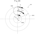
- Fig. 23 is a cross section showing the planetary gear mechanism 81 as viewed from the power source side.
- the carrier 81A, the sun gear 81B and the ring gear 81C are arranged concentrically. That is, the center axis S (rotation center axes) of the carrier 81A, the sun gear 81B and the ring gear 81C is in agreement.
- the planet gear 81D is arranged to contact an outer periphery of the sun gear 81B and an inner periphery of the ring gear 81C.
- the planet gear 81D is meshed with the sun gear 81B and the ring gear 81C.
- the carrier 81A, the sun gear 81B and the ring gear 81C are, for establishing the meshing of the respective gears, supported on a casing of the planetary stepless speed-changing mechanism 24 to be capable of rotating about the center axis S and to be incapable of moving in the other direction.
- the planet gear 81D is supported on the carrier 81A to be capable of rotating about the rotating axis Sp as the center axis of the planet gear 81D and to be incapable of moving in the other direction.
- the planet gear 81D rotates about the rotating axis Sp of the planet gear 81D while revolving about the center axis S of the carrier 81A.
- the limiting condition of the planetary gear mechanism 81 lies, as shown in Fig. 23 , in that the sun gear 81B, the ring gear 81C and the planet gear 81D are required to be meshed. In addition, for securing the strength of gears, it is necessary to make a diameter of the planet gear 81D large. That is, the limiting condition of the planetary gear mechanism 81 lies in that a mesh radius rs of the sun gear 81B becomes smaller by a large magnitude than a mesh radius rr of the ring gear 81C .
- No.2-A in Table 6 is configured such that the carrier 81A is connected to the second connecting member 31 linked to the engine 9 (power source). Therefore, torque Tc of the carrier 81A is a torque that the engine 9 can generate.
- the sun gear 81B is connected to the first connecting member 30 linked to the first variator 33. Therefore, torque Ts of the sun gear 81B is a torque that the first variator 33 can generate.
- the ring gear 81C is connected to the third connecting member 32 linked to the idler element 28. Therefore, torque Tr of the ring gear 81C is a torque reaction receiving from the idler gear 28B.
- No.2-B in Table 6 is configured such that the ring gear 81C is connected to the second connecting member 31 . Therefore, the torque Tr of the ring gear 81C is a torque that the engine 9 can generate.
- the carrier 81A is connected to the first connecting member 30. Therefore, the torque Tc of the carrier 81A is a torque that the first variator 33 can generate.
- the sun gear 81B is connected to the third connecting member 32. Therefore, the torque Ts of the sun gear 81B is a torque reaction receiving from the idler gear 28B.
- No.2-C in Table 6 is configured such that the carrier 81A is connected to the second connecting member 31 , the ring gear 81C is connected to the first connecting member 30 and the sun gear 81B is connected to the third connecting member 32.
- No.2-D in Table 6 is configured such that the ring gear 81C is connected to the second connecting member 31, the sun gear 81B is connected to the first connecting member 30 and the carrier 81A is connected to the third connecting member 32.
- No.2-E in Table 6 is configured such that the sun gear 81B is connected to the second connecting member 31, the ring gear 81C is connected to the first connecting member 30 and the carrier 81A is connected to the third connecting member 32.
- No.2-F in Table 6 is configured such that the sun gear 81B is connected to the second connecting member 31, the carrier 81A is connected to the first connecting member 30 and the ring gear 81C is connected to the third connecting member 32.
- the torque Ts of the sun gear 81B, the torque Tr of the ring gear 81C and the torque Tc of the carrier 81A can be calculated based upon the mesh radius rr of the ring gear 81C and the mesh radius rs of the sun gear 81B. Since the mesh radius rr of the ring gear 81C and the mesh radius rs of the sun gear 81B are determined by the mesh radii of the respective gears, the radius cannot be changed during the time when the planetary stepless speed-changing mechanism 24 is transmitting the power. Therefore, a ratio of the torque Ts of the sun gear 81B, the torque Tr of the ring gear 81C and the torque Tc of the carrier 81A does not change during the time when the planetary stepless speed-changing mechanism 24 is transmitting the power.
- the controller 25 outputs a signal for controlling the first variator 33 based upon this principle and controls the torque of the first connecting member 30 (for example, the sun gear 81B) linked to the first variator 33. That is, the controller 25 controls the torque of the first connecting member 30 (for example, the sun gear 81B) by controlling the first variator 33. Thereby, the controller 25 indirectly controls the torque of the second connecting member 31 (for example, the carrier 81A) linked to the engine 9 and the torque of the third connecting member 32 (for example, the ring gear 81C) linked to the idler element 28. As a result, the transmission torque can be controlled between the second connecting member 31 (for example, the carrier 81A) linked to the engine 9 and the third connecting member 32 (for example, the ring gear 81C) linked to the idler element 28.
- Vc The rotating speed of the carrier 81A
- Vs the rotating speed of the sun gear 81B
- Vr the rotating speed of the ring gear 81C
- Vr Vc ⁇ Kb Vs Vc + Kb + 1
- Kb rs rr
- Fig. 24 shows a relation of rotation speeds of the planetary gear mechanism 81.
- a speed relation line Y2 in Fig. 24 represents Formula 19 in a diagrammatic drawing.
- the controller 25 outputs a signal for controlling the first variator 33 based upon this principle and controls the rotation speed of the first connecting member 30 (for example, the sun gear 81B) linked to the first variator 33.
- the controller 25 controls the rotation speed of the first connecting member 30 (for example, the sun gear 81B) by controlling the first variator 33.
- the controller 25 indirectly controls the rotation speed of the second connecting member 31 (for example, the carrier 81A) linked to the engine 9 and the rotation speed of the third connecting member 32 (for example, the ring gear 81C) linked to the idler element 28.
- the speed change ratio can be controlled between the second connecting member 31 (for example, the carrier 81A) linked to the engine 9 and the third connecting member 32 (for example, the ring gear 81C) linked to the idler element 28.
- the sun gear 81B, the ring gear 81C and the planet gear 81D are required to be meshed with each other.
- the planetary gear mechanism 81 is large-sized. That is, a structural limit of the planetary gear mechanism 81 lies in that when the planetary gear mechanism 81 is designed to be small-sized, the mesh radius rs of the sun gear 81B is made smaller by a large magnitude than the mesh radius rr of the ring gear 81C. Therefore, in the planetary gear mechanism 81, a value of Kb is difficult to be made larger than 0.3 and is possibly made too smaller than a value of an idealistic value Kb.
- the planetary gear mechanism 81 adjusts the mesh radius rs of the sun gear 81B and the mesh radius rr of the ring gear 81C in accordance with the torque that can be absorbed by the first variator 33 and the allowable maximum rotation speed thereof based upon the relation formulas (the Formula 16, Formula 17 and Formula 18) of the torque Tc, Ts and Tr and the relation formulas (the Formula 19 and Formula 20) of the rotating speeds Vs, Vr and Vc.
- the second embodiment has a disadvantage in relation to the first embodiment in a point of providing the arrangement of the planetary gear mechanism 81 in which both of the torque that can be absorbed by the first variator 33 and the allowable maximum rotation speed thereof are optimized. That is, the second embodiment has a tendency that the first variator 33 becomes more expensive in relation to the first embodiment and has a possibility that the transmission efficiency of the planetary stepless speed-changing mechanism 24 is lowered.
- the size and the price of the first variator 33 are in proportion to a magnitude of the torque that can be absorbed by the first variator 33. Therefore, the absorbed torque of the first variator 33 is preferably smaller.
- the second embodiment (that is, No.2-A in Table 6) will be explained by taking a specific example thereof.
- the value of Kb in Formula 20 is preferably made small.
- the torque to be distributed to the first variator 33 is the smaller, the transmission efficiency of the planetary stepless speed-changing mechanism 24 can be further improved. Therefore, making the value of Kb in Formula 20 small is appropriate for the planetary stepless speed-changing mechanism 24.
- the value of Kb is made small based upon the speed relation line Y2 as shown in Fig. 24 , the rotation speed of the first variator 33 results in increase. Therefore, it is preferable that the value of Kb is made small within a range not exceeding the allowable maximum rotation speed of the first variator 33.
- the planetary gear mechanism 81 configured of the sun gear, the ring gear and the carrier has the structural limit that, as the planetary gear mechanism 81 is designed to be made small, the mesh radius rs of the sun gear 81B is made smaller by a large magnitude than the mesh radius rr of the ring gear 81C. Therefore, as the planetary gear mechanism 81 is designed to be small-sized, the value of Kb becomes too small.
- the rotation speed of the first variator 33 becomes high, which possibly exceeds the allowable maximum rotation speed of the first variator 33. Therefore, the planetary gear mechanism 81 operable in a high rotation becomes necessary. That is, there is a possibility that the first variator 33 becomes as expensive as to be capable of responding to the high rotation, the planetary gear mechanism 81 becomes large-sized and the transmission efficiency of the planetary stepless speed-changing mechanism 24 is lowered.
- the planetary gear mechanism 29 in the first embodiment will be compared with the planetary gear mechanism 81 in the second embodiment. That is, the two planetary gear mechanisms 29, 81 each have an advantage due to the distinction, and it cannot be completely said that one of them is more excellent. That is, in a case of being capable of freely setting the torque that can be absorbed by the first variator 33 and the allowable maximum rotation speed thereof, it is preferable to adopt the structurally simple planetary gear mechanism 81. Therefore, the first variator 33 is designed to adapt to the structural limit (the value of Kb) of the mesh radius rs of the sun gear 81B and the mesh radius rr of the ring gear 81C in the planetary gear mechanism 81. Thereby, the first variator 33 that is small-sized and inexpensive can be used. As a result, the planetary gear mechanism 81 can be simplified and the transmission efficiency of the planetary stepless speed-changing mechanism 24 can be improved.
- the planetary gear mechanism 29 in the first embodiment, by setting the value of Ka to the idealistic value and the inclination of the speed relation line Y1 as shown in Fig. 7 to the idealistic value, it is preferable to be capable of using all of the torque that can be absorbed by the first variator 33 and the allowable maximum rotation speed thereof.
- the first variator 33 that is small-sized and inexpensive can be used and the transmission efficiency of the planetary stepless speed-changing mechanism 24 can be improved.
- the internal lockup speed change ratio In can be calculated.
- the rotating speed Vs of the sun gear 81B connected to the first connecting member 30 is substituted as 0 to Formula 19. That is, the internal lockup speed change ratio In is found according to the following Formula 21.
- Vr Vc Kb + 1
- In Kb + 1
- the internal lockup speed change ratio In of the planetary stepless speed-changing mechanism 24 according to the second embodiment depends upon a combination of gears in the planetary gear mechanism 81 and Kb.
- the speed-changing device 21 is provided with the input shaft 22 (input member), the output shaft 23 (output member), the planetary gear mechanism 81 (planetary mechanism), the first variator 33, the second variator 34 and the controller 25.
- the planetary gear mechanism 81 is configured to include three members of the carrier 81A, the sun gear 81B (sun member) rotating about the rotation center axis of the carrier 81A and the ring gear 81C (ring member) that is positioned closer to the radial outside than the sun gear 81B and rotates about the rotation center axis of the carrier 81A.
- the carrier 81A as the first member that is one of the three members is connected via the second connecting member 31 (the other member) to the input shaft 22.
- the sun gear 81B as the second member apart from the carrier 81A is connected via the first connecting member 30 and the second clutch 36 (any of them is the other member) to the first variator 33.
- the ring gear 81C as the third member apart from the carrier 81A and the sun gear 81B is connected via the third connecting member 32, the idler element 28 and the multistage speed-changing mechanism 26 (any of them is the other member) to the output shaft 23.
- the carrier 81A (first member) may be connected directly to the input shaft 22.
- the sun gear 81B (second member) may be connected directly to the first variator 33.
- the ring gear 81C (third member) may be connected directly to the output shaft 23.
- the planet gear 81D (planet member) is supported on the carrier 81A, the planet gear 81D performing the power transmission while revolving about the rotation center axis S of the carrier 81A and rotating with the sun gear 81B and the ring gear 81C.
- the planetary gear mechanism 81 distributes the torque transmitted to the carrier 81A (first member) of the planetary gear mechanism 81 from the engine 9 to the sun gear 81B (second member) and the ring gear 81C (third member).
- the planetary gear mechanism 81 performs the rotation motion with two degrees of freedom between the carrier 81A, the sun gear 81B and the ring gear 81C.
- the second variator 34 transmits the power transmitted from the first variator 33 to the load (output shaft 23) or the power source (input shaft 22), or transmits the power transmitted from the load (output shaft 23) or the power source (input shaft 22) to the first variator 33.
- the controller 25 changes the rotation speed of the first variator 33 to change the rotation speed of the output shaft 23 in relation to the rotation speed of the input shaft 22.
- the speed-changing device 21 in the second embodiment performs the speed change steplessly by the planetary gear mechanism 81 and transmits the power transmitted from the power source (input shaft 22) to the load (output shaft 23) or transmits the power transmitted from the load (output shaft 23) to the power source (input shaft 22).
- the speed-changing device 21 is provided with the planetary gear mechanism 81 disposed between the input shaft 22 and the output shaft 23, the first variator 33 connected to the planetary gear mechanism 81, and the second variator 34 for transmitting the power transmitted from the first variator 33 to the load or the power source.
- the planetary gear mechanism 81 is provided with the carrier 29A that is connected to the input shaft 22 and on which the planet gear 81D is supported, the sun gear 81B connected to the first variator 33, and the ring gear 81C connected via the idler element 28 and the multistage speed-changing mechanism 26 to the output shaft 23.
- the speed-changing device 21 is provided with at least one of the internal lockup and the external lockup (direct connecting mechanism 27). The speed-changing device 21 can perform the switching between the power transmission by the planetary stepless speed-changing mechanism 24 and the power transmission by the lockup. Therefore, the second embodiment can also achieve the same functional effects as those in the first embodiment.
- the speed-changing device 21 is provided with two power transmission routes composed of the first power transmission route (planetary stepless speed-changing mechanism 24) and the second power transmission route (direct connecting mechanism 27).
- the transmission efficiency can improve more than the configuration of performing the internal lockup only.
- the controller 25 stops the rotation of the sun gear 81B (second member) in the planetary gear mechanism 81 to realize the state of the internal lockup.
- the controller 25 outputs a command of making the rotation speed be 0 to the first variator 33.
- the controller 25 outputs a command of stopping the rotation of the member to be connected to the first variator 33 by a mechanical engagement.
- the controller 25 outputs a command of blocking the power to be sent to the second variator 34 from the first variator 33.
- the controller 25 stops the rotation of the sun gear 81B.
- the internal lockup can be realized by stopping the rotation of the sun gear 81B in the planetary gear mechanism 81 to improve the transmission efficiency.
- the lockup rotation speed ratio is larger than the synchronization rotation speed ratio. Therefore, at the time of transmitting the power through the second power transmission route (direct connecting mechanism 27) as the external lockup mechanism, the speed can increase.
- the controller 25 disconnects the second clutch 36 during the time a vehicle is stopped. As a result, when a vehicle speed of the vehicle is 0, the power transmission to the first variator can be blocked.
- the controller 25 engages the second clutch 36 for stopping the sun gear 81B (second member). In addition, the controller 25 disengages the third clutch 37. Therefore, at the internal lockup the power transmission to the second variator 34 can be blocked.
- the controller 25 disengages at least one of the second clutch 36 and the third clutch 37 when the first clutch 27C is engaged. Therefore, at the external lockup the power transmission to at least one of the first variator 33 and the second variator 34 can be blocked.
- the speed-changing device 21 is provided with the multistage speed-changing mechanism 26 as a sub speeding-changing mechanism between the ring gear 81C (third member) and the output shaft 23 (output member). Therefore, the speed-changing device 21 can reverse the rotation direction of the load (output shaft 23).
- the second variator 34 is connected to the idler element 28 (specifically, the idler gear 28B as a rotation element) disposed between the planetary gear mechanism 81 and the multistage speed-changing mechanism 26.
- the second variator 34 may be configured to be connected to a rotation element disposed between the input shaft 22 (input member) and the drive source (engine 9), a rotation element configuring the multistage speed-changing mechanism 26, a rotation element disposed between the multistage speed-changing mechanism 26 and the output shaft 23 (output member), the output shaft 23 (output member), or a rotation element disposed between the output shaft 23 and the load.
- Fig. 30 shows a twelfth modification example.
- the second variator 34 is connected to the input gear 27A of the direct connecting mechanism 27 disposed in the input shaft 22. That is, the second variator 34 is connected between the planetary gear mechanism 29 and the input shaft 22 (input member).
- the second variator 34 may be configured to be connected closer to the engine 9-side (drive source side) than the planetary gear mechanism 29.
- the illustration is omitted but the second variator 34 may be connected to the lockup gear 27B in the direct connecting mechanism 27.
- Fig. 31 shows a thirteenth modification example.
- the second variator 34 is connected to the third connecting member 32 linked to the idler element 28.
- Fig. 32 shows a fourteenth modification example.
- the second variator 34 is connected to the odd numbered stage gear 55 of the multistage speed-changing mechanism 26. It should be noted that the illustration is omitted but the second variator 34 may be connected to the even numbered stage gear 62 of the multistage speed-changing mechanism 26.
- Fig. 33 shows a fifteenth modification example. In the fifteenth modification example, the second variator 34 is connected to the forward one-speed gear 56 of the multistage speed-changing mechanism 26.
- Fig. 34 shows a sixteenth modification example, wherein the second variator 34 is connected to the forward three-speed gear 57 of the multistage speed-changing mechanism 26.
- Fig. 35 shows a seventeenth modification example, wherein the second variator 34 is connected to the forward two-speed gear 63 of the multistage speed-changing mechanism 26.
- Fig. 36 shows an eighteenth modification example, wherein the second variator 34 is connected to the forward four-speed gear 64 of the multistage speed-changing mechanism 26.
- Fig. 37 shows a nineteenth modification example, wherein the second variator 34 is connected to the backward one-speed gear 65 of the multistage speed-changing mechanism 26. It should be noted that the illustration is omitted but the second variator 34 may be connected to the counter gear 54 of the multistage speed-changing mechanism 26.
- Fig. 38 shows a twentieth modification example, wherein the second variator 34 is connected to the output shaft 53 of the multistage speed-changing mechanism 26 (output shaft 23 in the speed-changing device 21). It should be noted that the illustration is omitted but the second variator 34 may be connected to the one-speed output gear 71, the two-speed output gear 72, the three-speed output gear 73, the four-speed output gear 74 or the backward one-speed output gear 75 in the multistage speed-changing mechanism 26.
- Fig. 39 shows a twenty-first modification example, wherein the second variator 34 is connected closer to the load side (front axle 12-side and rear axle 13-side) than the output shaft 23 in the speed-changing device 21.
- the second variator 34 may be connected to the front axle 12, the rear axle 13, the front propeller shaft 14 or the rear propeller shaft 15.
- the idler element 28 (idler gear 28B) and the multistage speed-changing mechanism 26 can be small-sized by connecting the second variator 34 closer to the output shaft 53-side than the idler gear 28B. Thereby, the speed-changing device 21 can be manufactured in lower costs.
- the explanation is made by taking the speed-changing device 21 provided with the multistage speed-changing mechanism 26 as an example.
- the multistage speed-changing mechanism 26 may be omitted in the speed-changing device 21.
- the planetary gear mechanism 29 in the planetary stepless speed-changing mechanism 24 can be connected to the output shaft 23 (output member).
- the second variator 34 may be connected closer to the output shaft 23-side (output member side) than the planetary gear mechanism 29, and the second variator 34 may be connected closer to the input shaft 22-side (input member side) than the planetary gear mechanism 29.
- the explanation is made by taking the speed-changing device 21 provided with the direct connecting mechanism 27 as the external lockup as an example, but the direct connecting mechanism 27 may be omitted.
- the first embodiment is explained by taking a case where the speed-changing device 21 is mounted on the wheel loader 1 as an example.
- the speed-changing device 21 may be mounted on working vehicles (construction machines) of hydraulic excavators, hydraulic cranes, dump trucks, forklifts and the like other than the wheel loader.
- the speed-changing device 21, not limited to the working vehicles can be applied widely as speed-changing devices incorporated in various vehicles of automobiles, railway vehicles and the like, or various industrial machines and general machinery. This is similarly applied to the second embodiment and the respective modification examples.
Landscapes
- Engineering & Computer Science (AREA)
- General Engineering & Computer Science (AREA)
- Mechanical Engineering (AREA)
- Mining & Mineral Resources (AREA)
- Civil Engineering (AREA)
- Structural Engineering (AREA)
- Transmission Devices (AREA)
- Structure Of Transmissions (AREA)
- Control Of Fluid Gearings (AREA)
Abstract
Description
- The present invention relates to speed-changing devices that are mounted on vehicles, such as wheel loaders or hydraulic excavators.
- For example,
Patent Document 1 describes a construction machine that performs transmission of power by a planetary stepless speed-changing mechanism composed of a combination of a planetary gear mechanism and an electric motor. According to the construction machine ofPatent Document 1, the planetary stepless speed-changing mechanism is used to reduce a rapid change in a rotation speed of an engine, thus making it possible to suppress an operating speed of a cargo working machine from rapidly changing. - Patent Document 1:
Japanese Patent Laid-Open No. 2008-247269 A Japanese Patent No. 5095252 - There is, however, the technology described in
Patent Document 1 has a possibility that it cannot effectively use a speed-changing range in speed multiplication of a planetary stepless speed-changing mechanism. - An object of the present invention is to provide a speed-changing device that can effectively use a speed-changing range in speed multiplication of a planetary stepless speed-changing mechanism. The present invention is defined by the appended claims. In the following, parts of the description and drawings referring to former embodiments which do not necessarily comprise all features to implement embodiments of the claimed invention are understood to not represent embodiments of the invention but to relate to be examples useful for understanding the embodiments of the invention.
- A speed-changing device according to a first aspect of the present invention comprises: an input shaft linked to a power source; an output shaft linked to a load; a planetary mechanism disposed between the input shaft and the output shaft; a first variator connected to the planetary mechanism; a second variator disposed apart from the first variator; and a controller configured to change a rotation speed of the first variator, characterized in that: the planetary mechanism is configured to include three members of a carrier, a first sun member rotating about a rotation center axis of the carrier and a second sun member rotating about the rotating center axis of the carrier, wherein a first member that is one of the three members in the planetary mechanism is connected directly or via another member to the input shaft, a second member apart from the first member of the three members in the planetary mechanism is connected directly or via another member to the first variator, a third member apart from the first member and the second member of the three members in the planetary mechanism is connected directly or via another member to the output shaft, and a planet member and a balance member are supported on the carrier of the planetary mechanism, the planet member and the balance member performing power transmission while revolving about the rotation center axis of the carrier and rotating with the first sun member and the second sun member, wherein the planetary mechanism distributes torque transmitted to the planetary mechanism from the power source to the second member and the third member, the planetary mechanism performs a rotation motion with two degrees of freedom between the first member, the second member and the third member, the second variator transmits power transmitted from the first variator to the load or the power source, or transmits power transmitted from the load or the power source to the first variator, and the controller changes a rotation speed of the first variator to change a rotation speed of the output shaft in relation to a rotation speed of the input shaft.
- A speed-changing device according to a second aspect of the present invention comprises: an input shaft linked to a power source; an output shaft linked to a load; a planetary mechanism disposed between the input shaft and the output shaft; a first variator connected to the planetary mechanism; a second variator disposed apart from the first variator; and a controller configured to change a rotation speed of the first variator, characterized in that: the planetary mechanism is configured to include three members of a carrier, a sun member rotating about a rotation center axis of the carrier and a ring member positioned closer to a radial outside than the sun member and rotating about the rotation center axis of the carrier, wherein a first member that is one of the three members in the planetary mechanism is connected directly or via another member to the input shaft, a second member apart from the first member of the three members in the planetary mechanism is connected directly or via another member to the first variator, a third member apart from the first member and the second member of the three members in the planetary mechanism is connected directly or via another member to the output shaft, and a planet member is supported on the carrier of the planetary mechanism, the planet member performing power transmission while revolving about the rotation center axis of the carrier and rotating with the sun member and the ring member, wherein the planetary mechanism distributes torque transmitted to the planetary mechanism from the power source to the second member and the third member, the planetary mechanism performs a rotation motion with two degrees of freedom between the first member, the second member and the third member, the second variator transmits power transmitted from the first variator to the load or the power source, or transmits power transmitted from the load or the power source to the first variator, and the controller changes a rotation speed of the first variator to change a rotation speed of the output shaft in relation to a rotation speed of the input shaft, further comprising a first power transmission route as a power transmission route for transmitting the power from the power source through the planetary mechanism to the load, a second power transmission route that is disposed in parallel with the first power transmission route to transmit the power to the load by meshing of gears each other without via the planetary mechanism, and a first clutch disposed in the second power transmission route to switch the engagement and disengagement, wherein the controller engages the first clutch to perform power transmission through the second power transmission route.
- According to the aspect of the present invention, it is possible to effectively use the speed-changing range in speed multiplication of the planetary stepless speed-changing mechanism including the planetary mechanism, the first variator and the second variator.
-
-
Fig. 1 is a left side view showing a wheel loader on which a speed-changing device according to a first embodiment of the present invention is mounted. -
Fig. 2 is a partially broken side view showing the speed-changing device inFig. 1 . -
Fig. 3 is a configuration diagram showing the speed-changing device according to the first embodiment. -
Fig. 4 is a configuration diagram showing the speed-changing device inFig. 3 together with an internal part of a planetary mechanism. -
Fig. 5 is an enlarged view showing (V) part inFig. 4 . -
Fig. 6 is an explanatory diagram showing the planetary mechanism as viewed from a power source side. -
Fig. 7 is a characteristic diagram showing a relation of rotation speeds between respective members in the planetary mechanism ("No.1-A" in Table 4 to be described later) inFig. 4 . -
Fig. 8 is a characteristic diagram showing a relation of rotation speeds between respective members in the planetary mechanism ("No.1-C" in Table 4 to be described later) inFig. 4 . -
Fig. 9 is a characteristic diagram showing a relation of rotation speeds between respective members in the planetary mechanism ("No.1-B" in Table 4 to be described later) inFig. 4 . -
Fig. 10 is an enlarged view showing (X) part inFig. 4 . -
Fig. 11 is a drive force diagram showing an idealistic relation between vehicle speeds and traction forces of a wheel loader. -
Fig. 12 is a drive force diagram showing an idealistic relation between vehicle speeds and traction forces of a wheel loader according to the first embodiment. -
Fig. 13 is a configuration diagram as similar toFig. 3 , showing a first modification example (configuration without external lockup). -
Fig. 14 is a configuration diagram as similar toFig. 3 , showing a second modification example (configuration for executing internal lockup by a brake). -
Fig. 15 is a configuration diagram as similar toFig. 3 , showing a third modification example (configuration for performing internal lockup by a brake and without an idling member) . -
Fig. 16 is a drive force diagram showing a relation between vehicle speeds and traction forces of a wheel loader on which a speed-changing device without external lockup is mounted. -
Fig. 17 is a drive force diagram showing a relation between vehicle speeds and traction forces of a wheel loader on which a speed-changing device without internal lockup is mounted. -
Fig. 18 is a configuration diagram as similar toFig. 4 , showing a fourth modification example (configuration in which an input shaft is connected to a first sun member and a first variator is connected to a carrier). -
Fig. 19 is a configuration diagram as similar toFig. 4 , showing a fifth modification example (configuration in which an input shaft is connected to a first sun member and a first variator is connected to a second sun member). -
Fig. 20 is a configuration diagram as similar toFig. 4 , showing a fifth modification example (configuration in which a second variator is connected to an output shaft). -
Fig. 21 is a configuration diagram as similar toFig. 4 , showing a second embodiment. -
Fig. 22 is an enlarged view showing (XXII) part inFig. 21 . -
Fig. 23 is an explanatory diagram showing a planetary mechanism inFig. 21 as viewed from a power source side. -
Fig. 24 is a characteristic diagram showing a relation of rotation speeds of three members in the planetary mechanism inFig. 21 . -
Fig. 25 is a configuration diagram as similar toFig. 21 , showing a seventh modification example (configuration in which an input shaft is connected to a ring member and a first variator is connected to a carrier). -
Fig. 26 is a configuration diagram as similar toFig. 21 , showing an eighth modification example (configuration in which an input shaft is connected to a carrier and a first variator is connected to a ring member). -
Fig. 27 is a configuration diagram as similar toFig. 21 , showing a nineth modification example (configuration in which an input shaft is connected to a ring member and a first variator is connected to a sun member). -
Fig. 28 is a configuration diagram as similar toFig. 21 , showing a tenth modification example (configuration in which an input shaft is connected to a sun member and a first variator is connected to a ring member). -
Fig. 29 is a configuration diagram as similar toFig. 21 , showing an eleventh modification example (configuration in which an input shaft is connected to a sun member and a first variator is connected to a carrier). -
Fig. 30 is a configuration diagram as similar toFig. 3 , showing a twelfth modification example (configuration in which a second variator is connected to an input shaft). -
Fig. 31 is a configuration diagram as similar toFig. 3 , showing a thirteenth modification example (configuration in which a second variator is connected to a third connecting member linked to an idler element). -
Fig. 32 is a configuration diagram as similar toFig. 3 , showing a fourteenth modification example (configuration in which a second variator is connected to an odd-numbered stage gear in a multistage speed-changing mechanism). -
Fig. 33 is a configuration diagram as similar toFig. 3 , showing a fifteenth modification example (configuration in which a second variator is connected to a forward one-speed gear in a multistage speed-changing mechanism). -
Fig. 34 is a configuration diagram as similar toFig. 3 , showing a sixteenth modification example (configuration in which a second variator is connected to a forward three-speed gear in a multistage speed-changing mechanism). -
Fig. 35 is a configuration diagram as similar toFig. 3 , showing a seventeenth modification example (configuration in which a second variator is connected to a forward two-speed gear in a multistage speed-changing mechanism). -
Fig. 36 is a configuration diagram as similar toFig. 3 , showing an eighteenth modification example (configuration in which a second variator is connected to a forward four-speed gear in a multistage speed-changing mechanism). -
Fig. 37 is a configuration diagram as similar toFig. 3 , showing a nineteenth modification example (configuration in which a second variator is connected to a backward one-speed gear in a multistage speed-changing mechanism). -
Fig. 38 is a configuration diagram as similar toFig. 3 , showing a twenty-first modification example (configuration in which a second variator is connected to an output shaft). -
Fig. 39 is a configuration diagram as similar toFig. 3 , showing a twentieth modification example (configuration in which a second variator is connected closer to a load-side than an output shaft in a speed-changing device). - Hereinafter, transmissions according to embodiments in the present invention will be in detail explained with reference to the accompanying drawings by taking a case of being applied to a wheel loader as an example.
-
Fig. 1 to Fig. 12 show a first embodiment. InFig. 1 , awheel loader 1 is a representative example of a vehicle (working machine). Thewheel loader 1 is configured as an articulate type working vehicle in which afront vehicle body 3 provided with left and rightfront wheels 2 and arear vehicle body 5 provided with left and rightrear wheels 4 are connected to be capable of bending in the left-right direction. Thefront vehicle body 3 and therear vehicle body 5 configure a vehicle body of thewheel loader 1. Acenter hinge 6 and a steering cylinder (not shown) are disposed between thefront vehicle body 3 and therear vehicle body 5, and expansion/contraction of the steering cylinder enables thefront vehicle body 3 and therear vehicle body 5 to bend about thecenter hinge 6 in the left-right direction. Thereby, thewheel loader 1 can perform the steering at the traveling. - A
cargo working machine 7 called also a working mechanism is disposed in thefront vehicle body 3 of thewheel loader 1 to be capable of tilting/lifting thereto. Thecargo working machine 7 is provided with aloader bucket 7A. On the other hand, acab 8 that defines therein an operating room, anengine 9, ahydraulic pump 10, a speed-changingdevice 21 as a transmission (power transmission device) and the like are arranged in therear vehicle body 5 of thewheel loader 1. Theengine 9 is a power source (prime mover) of thewheel loader 1. The power source can be configured of theengine 9 as a unit that is an internal combustion engine, and besides, may be configured of, for example, an engine and an electric motor or an electric motor unit. Thehydraulic pump 10 is connected to theengine 9. Thehydraulic pump 10 is a hydraulic source for operating thecargo working machine 7. As shown inFig. 3 to be described later, thehydraulic pump 10 is connected viagears engine 9. - A
front axle 12 extending in the left-right direction is provided under thefront vehicle body 3. The left and rightfront wheels 2 are provided on both end sides of thefront axle 12. On the other hand, arear axle 13 extending in the left-right direction is provided under therear vehicle body 5. The left and rightrear wheels 4 are provided on both end sides of therear axle 13. - The
front axle 12 is connected through afront propeller shaft 14 to the speed-changingdevice 21. Therear axle 13 is connected through arear propeller shaft 15 to the speed-changingdevice 21. The speed-changingdevice 21 increases and decreases rotation of theengine 9 to be transmitted to thefront propeller shaft 14 and therear propeller shaft 15. Power from theengine 9 is transmitted to the speed-changingdevice 21 connected to theengine 9. - The power from the
engine 9 is adjusted in a rotation number and in a rotation direction by the speed-changingdevice 21, which is then transmitted from afront output shaft 23A and arear output shaft 23B via thefront propeller shaft 14 and therear propeller shaft 15 to thefront axle 12 and therear axle 13. That is, as illustrated inFig. 2 , the speed-changingdevice 21 is provided with aninput shaft 22 connected to theengine 9, afront output shaft 23A connected to thefront propeller shaft 14 and arear output shaft 23B connected to therear propeller shaft 15. The speed-changingdevice 21 switches a power transmission route in the speed-changingdevice 21 to perform a speed change and a forward rotation/reverse rotation between theinput shaft 22 and theoutput shafts - Next, an explanation will be made of an operation of the
wheel loader 1. Thewheel loader 1 repeats an operation pattern such as a V cycle in which a dump loading work is mainly performed or load and carry of direct input to a hopper or the like. The V cycle is the operation pattern of, after the starting-up, excavating earth and sand or the like, which is then loaded on a dump. The load and carry are the operation pattern of, after the starting-up, excavating earth and sand or the like, transporting it (high-load travel), discharging it to a dump, and deadheading (low-load travel). Thewheel loader 1 needs to frequently switch the speed-changingdevice 21 for obtaining travel speeds and drive forces optimal to various working states of starting-up, transporting, loading, deadheading and the like. - At the excavating and the starting-up, the speed-changing
device 21 needs a high traction force. Therefore, the speed-changingdevice 21 needs to increase a reduction ratio to raise output torque of theoutput shafts wheel loader 1 is 0km/h (the rotation speed of theoutput shafts input shaft 22 needs to be kept in a predetermined value or more in such a manner that theengine 9 as the power source does not stop, and a change gear ratio of the speed-changingdevice 21 needs to be limitless. It should be noted that the vehicle speed of thewheel loader 1 at the excavating is 0 to 4km/h, for example. - At the transporting, the speed-changing
device 21 needs to perform power transmission from theinput shaft 22 to theoutput shafts wheel loader 1 raises up thecargo working machine 7 while transporting. Therefore, when a raising-up speed of thecargo working machine 7 rapidly slows, thecargo working machine 7 is possibly forced to collide with the dump. Therefore, upon approaching the dump, it is preferable to be capable of suppressing a rapid change in discharge flow rate of thehydraulic pump 10. In addition, in order to do so, it is necessary to control the speed-changingdevice 21 in such a manner that the rotation speed of theengine 9 does not change rapidly. At the time of discharging earth and sand to the dump, the vehicle speed for approaching the dump is 0 to 7km/h, for example. In this vehicle speed, it is preferable to be capable of suppressing the rapid variation in a rotation speed of theengine 9. - At the deadheading of a vehicle traveling in a non-loading state in an ordinary road or in a working site, the speed-changing
device 21 needs to perform the power transmission from theinput shaft 22 to theoutput shafts cargo working machine 7 is not needed. Therefore, a rapid change in a rotation speed of theengine 9 is allowable. For fuel saving, however, the power transmission needs to be performed from theinput shaft 22 to theoutput shafts -
Fig. 11 shows an idealistic drive force diagram of thewheel loader 1. InFig. 11 , an idealistic drive force line Lf in the forward direction and an idealistic drive force line Lr in the backward direction (retreat direction) are shown. At the forwarding time, a high traction force is required at the excavating, and a travel in a high vehicle speed (0 to 40km/h) is required at the deadheading. In addition, thewheel loader 1 needs to stably travel on the upslope at various grades provided in a quarry or the like. Therefore, for example, at a vehicle speed of 3km/h or more, a traction force is preferably the iso-horsepower regardless of the vehicle speed. - A range A in
Fig. 11 shows a range in which a high traction force is required for excavation, that is, a range A of a drive power line at the excavating. A range B inFig. 11 shows a range in which a traction force of the iso-horsepower is required regardless of the vehicle speed, that is, a range B of a drive power line of the iso-horsepower in the forward direction. A range C inFig. 11 shows a range in which a traction force of the iso-horsepower is required regardless of the vehicle speed, that is, a range C of a drive power line of the iso-horsepower in the backward direction. The followingFormula 1 is established in the range B of the drive power line of the iso-horsepower in the forward direction and in the range C of the drive power line of the iso-horsepower in the backward direction.Traction force [N] × vehicle speed [km/h] × (5/18) = constant - It should be noted that the
wheel loader 1 does not perform excavation in the backward direction. Therefore, the maximum traction force of the idealistic drive force line Lr in the backward direction is lower than at the forwarding time. - Incidentally, in the speed-changing
device 21 to be used in a working vehicle of thewheel loader 1 or the like, the switching between the power transmission by the stepless speed-changing mechanism and the power transmission by the lockup mechanism is preferably made possible. In this case, it is preferable that the speed-changingdevice 21 can effectively use the speed-hanging range in speed multiplication of the stepless speed-changing mechanism. In addition to it, at the switching from the power transmission by the stepless speed-changing mechanism to the power transmission by the lockup mechanism, it is preferable that a change in an acceleration/deceleration of a vehicle can be made small. In addition, in a case where an upper limit value of a rotation speed and an upper limit value of generation (absorption) possible torque of a variator are limited, it is possible to provide an arrangement (gear arrangement) in which a change gear ratio (gear ratio) of a planetary mechanism (planetary gear mechanism) becomes an optimal value, preferably improving a transmission efficiency of a stepless speed-changing mechanism. - Therefore, as shown in
Fig. 3 andFig. 4 , the speed-changingdevice 21 according to the first embodiment is provided with a mode of transmitting power while steplessly speed-changing the planetary stepless speed-changingmechanism 24, a mode of transmitting power by internal lockup of the planetary stepless speed-changingmechanism 24 and a mode of transmitting power by an external lockup mechanism (a direct connecting mechanism 27) without via aplanetary gear mechanism 29. The power transmission by the internal lockup is carried out by stopping rotation of a rotation member (for example, a first sun gear) linked to afirst variator 33 of three rotation members (for example, a carrier, the first sun gear and a second sun gear) in theplanetary gear mechanism 29. Thereby, it is possible to effectively use the speed-changing range in speed multiplication of the planetary stepless speed-changingmechanism 24. - On the other hand, the power transmission by the external lockup is performed via the external lockup mechanism (direct connecting mechanism 27) attached to an exterior of the planetary stepless speed-changing
mechanism 24. In this case, the power transmission by the external lockup is performed in a state of stopping the power transmission by the planetary stepless speed-changingmechanism 24. This stop is performed by releasing (or reducing the torque) the rotation of the rotation member (for example, the first sun gear) linked to thefirst variator 33 of the three rotation members (for example, the carrier, the first sun gear and the second sun gear) in theplanetary gear mechanism 29. Thereby, it is possible to transmit the power in a transmission efficiency higher than the internal lockup, and it is possible to perform the power transmission by further increasing the speed-changing range in speed multiplication of the planetary stepless speed-changingmechanism 24. - Further, according to the first embodiment, as shown in
Fig. 4 to Fig. 6 , theplanetary gear mechanism 29 is provided with two sun gears 29B, 29C, aplanet gear 29D and abalance gear 29E revolving about a center axis S (Fig. 6 ) of the two sun gears 29B, 29C and rotating on its own axis, and onecarrier 29A supporting theplanet gear 29D and thebalance gear 29E to be capable of rotating about the center axis S of the two sun gears 29B, 29C. Thereby, theplanetary gear mechanism 29 can be provided with a gear arrangement in which a gear ratio becomes an optimal value. That is, by using theplanetary gear mechanism 29 with this gear arrangement, even in a case of using thefirst variator 33 that is inexpensive and small-sized and in which the upper limit value of the rotation speed and the upper limit vale of the generation (absorption) possible torque are limited, it is possible to improve the transmission efficiency of the planetary stepless speed-changingmechanism 24. - Hereinafter, an explanation will be in detail made of the speed-changing
device 21 according to the first embodiment. It should be noted that inFig. 3 , theplanetary gear mechanism 29 in the speed-changingdevice 21 is shown in a box, and on the other hand,Fig. 4 shows an internal part of theplanetary gear mechanism 29, that is, also a specific gear arrangement of theplanetary gear mechanism 29. In addition, inFig. 3 andFig. 4 , for avoiding complication of the figures, theoutput shaft 23 of the speed-changingdevice 21 is shown in a simple manner as the common output shaft 23 (=output shafts front axle 12 and therear axle 13. That is, inFig. 3 andFig. 4 , the configuration of dividing the power to theoutput shaft 23A on the front side and theoutput shaft 23B on the rear side through, for example, a center differential mechanism or the like is omitted in illustration. -
Fig. 3 andFig. 4 are configuration diagrams of the speed-changingdevice 21 according to the first embodiment, more specifically the speed-changingdevice 21 provided with both of the internal lockup and the external lockup. The speed-changingdevice 21 is provided with theinput shaft 22 as an input member, theoutput shaft 23 as an output member, the planetary stepless speed-changingmechanism 24 as a stepless speed-changing mechanism (main speed-changing mechanism), and acontroller 25. In addition, more preferably the speed-changingdevice 21 is provided with a multistage speed-changingmechanism 26 as a stepped speed-changing mechanism (sub speed-changing mechanism), and a direct connectingmechanism 27 as an external lockup mechanism. The direct connectingmechanism 27 is provided with a first clutch 27C to be connected at the time of transmitting the power through the direct connectingmechanism 27. In addition, the speed-changingdevice 21 is provided with an idler element 28 (anidler shaft 28A and anidler gear 28B) that mechanically connects the planetary stepless speed-changingmechanism 24, the multistage speed-changingmechanism 26 and the direct connectingmechanism 27. The planetary stepless speed-changingmechanism 24 configures a first power transmission route. The direct connectingmechanism 27 configures a second power transmission route. - The
engine 9 is connected to theinput shaft 22 of the speed-changingdevice 21. Theinput shaft 22 is provided with thegear 10B for transmitting the power to thehydraulic pump 10. Theinput shaft 22 is provided with aninput gear 27A of the direct connectingmechanism 27. Theinput shaft 22 is connected via a second connectingmember 31 to be described later to the planetary stepless speed-changing mechanism 24 (more specifically, the planetary gear mechanism 29). On the other hand, the power is outputted from theoutput shaft 23 of the speed-changingdevice 21. Theoutput shaft 23 of the speed-changingdevice 21 acts also as anoutput shaft 53 of the multistage speed-changingmechanism 26 to be described later. The power inputted from theinput shaft 22 is transmitted via the planetary stepless speed-changingmechanism 24 or the direct connectingmechanism 27 to theidler element 28. The power transmitted to theidler element 28 is outputted through the multistage speed-changingmechanism 26 from theoutput shaft 23. - The planetary stepless speed-changing
mechanism 24 forms a state of the internal lockup by stopping a first connectingmember 30 for connecting the planetary gear mechanism 29 (for example, afirst sun gear 29B) and thefirst variator 33. The state of the internal lockup is formed, for example, by braking thefirst variator 33 to stop the first connectingmember 30. When the planetary stepless speed-changingmechanism 24 is in a state of the internal lockup, the power inputted from theinput shaft 22 is transmitted through "a second connectingmember 31 for connecting the planetary gear mechanism 29 (for example, acarrier 29A) and theinput shaft 22", "theplanetary gear mechanism 29", and "a third connectingmember 32 for connecting the planetary gear mechanism 29 (for example, asecond sun gear 29C) and theidler element 28" to theidler element 28. This internal lockup will be described later. - In the first embodiment, the power transmission route for transmitting the power inputted from the
engine 9 to theinput shaft 22 to the multistage speed-changingmechanism 26 can be selected from any one of three routes of the following (A), (B) and (C). - (A) Stepless speed-changing route (first power transmission route via the planetary stepless speed-changing mechanism 24) for transmitting the power inputted from the
engine 9 to theinput shaft 22 to the multistage speed-changingmechanism 26 in a state where the planetary stepless speed-changingmechanism 24 is steplessly speed-changed. At this time, a first clutch 27C is disengaged, and a second clutch 36 and a third clutch 37 are connected (engaged). - (B) Internal lockup route (first power transmission route via the planetary stepless speed-changing mechanism 24) for transmitting the power inputted from the
engine 9 to theinput shaft 22 to the multistage speed-changingmechanism 26 in a state where the planetary stepless speed-changingmechanism 24 is made in the internal lockup. At this time, the first clutch 27C is disengaged, and the second clutch 36 is connected (engaged) . The third clutch 37 is connected (engaged) as needed. - (C) External lockup route (second power transmission route via the direct connecting
mechanism 27 without via the planetary stepless speed-changing mechanism 24) for transmitting the power inputted from theengine 9 to theinput shaft 22 via the direct connectingmechanism 27 to the multistage speed-changingmechanism 26. At this time, the first clutch 27C is connected (engaged), and the second clutch 36 and the third clutch 37 are disengaged as needed. - Thereby, at the time it is appropriate to steplessly speed-change the planetary stepless speed-changing
mechanism 24, it is possible to perform the power transmission by steplessly speed-changing the planetary stepless speed-changingmechanism 24. At the time it is appropriate to make the planetary stepless speed-changingmechanism 24 operate in the internal lockup, it is possible to perform the power transmission by making the planetary stepless speed-changingmechanism 24 operate in the internal lockup. At the time it is appropriate to perform the power transmission via the direct connectingmechanism 27, the power transmission can be performed via the direct connectingmechanism 27. - At the time it is appropriate to perform the power transmission by steplessly speed-changing the planetary stepless speed-changing
mechanism 24, the vehicle is at the excavating or at the transporting and the vehicle speed is in a range of 0 to 7km/h. This reason is shown as the following (a) to (c). - (a) The transmission efficiency at the starting-up and at the excavating of a vehicle is high.
- (b) It is possible to make a gear change ratio limitless. That is, even in a case where the
engine 9 is at the rotating, it is possible to transmit the torque to theoutput shaft 23 while stopping the rotation of theoutput shaft 23. Therefore, the first embodiment is appropriate for the excavating work. - (c) It is possible to control the torque transmitted to the
output shaft 23 through the speed-changingdevice 21 of the power generated by theengine 9. That is, the distribution of the power is made possible between thehydraulic pump 10 for operating thecargo working machine 7 and the speed-changingdevice 21. - At the time it is appropriate to perform the power transmission by making the planetary stepless speed-changing
mechanism 24 operate in the internal lockup, the vehicle is at the transporting or at the deadheading and the vehicle speed is in a range of 7 to 9km/h. This reason is shown as the following (d) and (e). - (d) As the vehicle speed becomes high, the transmission efficiency is higher in a case of performing the power transmission by making the planetary stepless speed-changing
mechanism 24 operate in the internal lockup than by making the planetary stepless speed-changingmechanism 24 steplessly speed-change. - (e) The switch from the stepless speed change to the internal lockup can be performed mechanically. Therefore, at the switching from the stepless speed change to the internal lockup, a rapid change in rotation of the
engine 9 can be suppressed. Thereby, a rapid change in a discharge flow rate of thehydraulic pump 10 can be suppressed to improve operability of thecargo working machine 7. Therewith, a change in torque of theoutput shaft 23 at the switching can be made small to improve a ride comfort of thewheel loader 1. - At the time it is appropriate to perform the transmission of the power via the direct connecting
mechanism 27, the vehicle is at the transporting and the vehicle speed is in a range of 9 to 13km/h. In addition, the vehicle is at the deadheading and the vehicle speed is in a range of 9 to 40km/h. This reason is as follows. In the external lockup of performing the transmission of the power via the direct connectingmechanism 27, the transmission efficiency of the power is the highest. That is, since the power is transmitted in the external lockup by meshing of a pair ofgears planetary gear mechanism 29. When the vehicle speed is 9km/h or less, there is a possibility that the excavation rapidly starts in the middle of the deadheading or transporting. On the other hand, in a case of switching the power transmission route from the direct connecting mechanism 27 (external lockup) to the planetary stepless speed-changingmechanism 24, it possibly takes time in this switching. Therefore, it is preferable not to use the direct connectingmechanism 27 when the vehicle speed is 9km/h or less. - Table 1 as follows shows a combination of power transmission routes in the speed-changing
device 21 provided with both of the internal lockup and the external lockup. In this case, the multistage speed-changingmechanism 26 is provided with a shift stage of a forward four-speed and a backward one-speed. Therefore, in a case of performing the power transmission via the direct connecting mechanism 27 (external lockup mechanism), the multistage speed-changingmechanism 26 can select a shift stage of a forward one-speed, a forward two-speed, a forward three-speed, a forward four-speed and a backward one-speed.[Table 1] Name of power transmission state Selection of planetary stepless speed-changing mechanism or external lockup mechanism Multistage speed-changing mechanism Vehicle speed [km/h] Operation of wheel loader forward one-speed stepless speed change planetary stepless speed-changing mechanism forward one- speed 0 to 9 excavation startup (stepless speed-changing operation) transport deadhead forward one-speed internal lockup planetary stepless speed-changing mechanism forward one- speed 7 to 9 transport deadhead (internal lockup operation) forward one-speed external lockup external lockup mechanism forward one- speed 9 to 14 transport deadhead forward two-speed external lockup external lockup mechanism forward two- speed 14 to 20 deadhead forward three-speed external lockup external lockup mechanism forward three- speed 20 to 28 deadhead forward four-speed external lockup external lockup mechanism forward four- speed 28 to 40 deadhead backward one-speed stepless speed change planetary stepless speed-changing mechanism backward one- speed 0 to 9.9 startup transport (stepless speed-changing operation) deadhead backward one-speed internal lockup planetary stepless speed-changing mechanism backward one-speed 7.7 to 9.9 transport deadhead (internal lockup operation) backward one-speed external lockup external lockup mechanism backward one-speed 9.9 to 15.4 transport deadhead - It should be noted that even in a case where a speed stage of the multistage speed-changing
mechanism 26 is any one of the forward two-speed, the forward three-speed and the forward four-speed, the power transmission may be performed via the planetary stepless speed-changingmechanism 24 without via the direct connectingmechanism 27. The operation of the planetary stepless speed-changingmechanism 24 at this time may be a stepless speed-changing operation or in a state of being in the internal lockup. However, when the planetary stepless speed-changingmechanism 24 is made to steplessly speed-change, the transmission efficiency of the planetary stepless speed-changingmechanism 24 is lower than in the internal lockup and the external lockup. Thereby, since the transmission efficiency of the speed-changingdevice 21 is lower, favorably it is preferable to select a combination of power transmission routes as shown in Table 1. -
Fig. 12 shows a drive force diagram of the speed-changingdevice 21 in which the internal lockup and the external lockup both are present. As shown inFig. 12 , as to the forward, the speed change is made possible in six stages of a forward one-speed stepless speed change Lf1, a forward one-speed internal lockup Lf2, a forward one-speed external lockup Lf3, a forward two-speed external lockup Lf4, a forward three-speed external lockup Lf5 and a forward four-speed external lockup Lf6. Thereby, the drive force diagram can be made as close as possible to the idealistic drive force line Lf in the forward direction. - On the other hand, as to the backward, the speed change is made possible in three stages of a backward one-speed stepless speed change Lr1, a backward one-speed internal lockup Lr2 and a backward one-speed external lockup Lr3. Thereby, the drive force diagram can be made as close as possible to the idealistic drive force line Lr in the backward direction. As a result, a high traction force can be obtained at the excavating, and a high vehicle speed (0 to 40km/h) can be obtained at the deadheading. In addition, the
wheel loader 1 stably travels on the upslopes at various grades. - It should be noted that, for realizing a broad speed change ratio width, it is preferable that the speed-changing
device 21 is provided with both of "the internal lockup of the planetary stepless speed-changingmechanism 24" and "the external lockup by the direct connectingmechanism 27". However, for achieving "to suppress a change in acceleration/deceleration of a vehicle at the switching of the power transmission from the stepless speed change to the lockup state while effectively using the speed changing range in speed multiplication of the planetary stepless speed-changingmechanism 24", the speed-changingdevice 21 may be provided with only one of the internal lockup and the external lockup. -
Fig. 13 shows a speed-changingdevice 21A according to a first modification example provided with only the internal lockup of the planetary stepless speed-changingmechanism 24 as a device for realizing the lockup. In the speed-changingdevice 21A according to the first modification example, the internal lockup operation of the planetary stepless speed-changingmechanism 24 is made possible but an external lockup mechanism (direct connecting mechanism 27) is not provided. Table 2 as follows shows a combination of power transmission routes of the speed-changingdevice 21A provided with the internal lockup only.[Table 2] Name of power transmission state Operation of planetary stepless speed-changing mechanism Multistage speed-changing mechanism Vehicle speed [km/h] Operation of wheel loader forward one-speed stepless speed change planetary stepless speed-changing mechanism forward one-speed 0 to 9 excavation startup (stepless speed-changing operation) transport deadhead forward one-speed internal lockup planetary stepless speed-changing mechanism forward one-speed 7 to 9 transport deadhead (internal lockup operation) forward two-speed internal lockup planetary stepless speed-changing mechanism forward two-speed 9 to 14 transport deadhead (internal lockup operation) forward three-speed internal lockup planetary stepless speed-changing mechanism forward three-speed 14 to 20 deadhead (internal lockup operation) forward four-speed internal lockup planetary stepless speed-changing mechanism forward four-speed 20 to 28 deadhead (internal lockup operation) forward five-speed internal lockup planetary stepless speed-changing mechanism forward five-speed 28 to 40 deadhead (internal lockup operation) backward one-speed stepless speed change planetary stepless speed-changing mechanism backward one-speed 0 to 9.9 startup transport (stepless speed-changing operation) deadhead backward one-speed internal lockup planetary stepless speed-changing mechanism backward one-speed 7.7 to 9.9 transport deadhead (internal lockup operation) backward two-speed internal lockup planetary stepless speed-changing mechanism backward two-speed 9.9 to 15.4 transport deadhead (internal lockup operation) - In the first modification example, the speed shift stages by the direct connecting mechanism 27 (external lockup) are reduced by one speed shift stage. Therefore, for obtaining a speed change ratio equivalent to that of the speed-changing
device 21 in which the internal lockup and the external lockup both are present, a multistage speed-changingmechanism 26A is provided with speed shift stages of forward five stages and backward two stages in the first modification example. In addition, the planetary stepless speed-changingmechanism 24 is provided with ablock mechanism 40 for realizing the internal lockup as to be described later in the first modification example.Fig. 14 shows a speed-changingdevice 21B according to a second modification example. The speed-changingdevice 21B according to the second modification example also omits the external lockup mechanism as to be similar to the first modification example. The second modification example is provided with abrake mechanism 41 for realizing the internal lockup to be described later. Further,Fig. 15 shows a speed-changingdevice 21C according to a third modification example. The speed-changingdevice 21C according to the third modification example omits the external lockup mechanism and is provided with thebrake mechanism 41, and further omits theidler element 28. That is, in a case of the configuration of omitting the direct connecting mechanism 27 (external lockup), theidler element 28 as well may be omitted. -
Fig. 16 shows drive force diagrams of the speed-changingdevices Fig. 13 ,Fig. 14 andFig. 15 ) provided with the planetary stepless speed-changing mechanism 24 (internal lockup) and not provided with the direct connecting mechanism 27 (external lockup). As shown inFig. 16 , as to the forward, the speed change is made possible in six stages of a forward one-speed stepless speed change Lf1, a forward one-speed internal lockup Lf2, a forward two-speed internal lockup Lf3, a forward three-speed internal lockup Lf4, a forward four-speed internal lockup Lf5 and a forward five-speed internal lockup Lf6. On the other hand, as to the backward, the speed change is made possible in three stages of a backward one-speed stepless speed change Lr1, a backward one-speed internal lockup Lr2 and a backward two-speed internal lockup Lr3. - On the other hand, the configuration of being provided with the external lockup only can be realized by not performing the internal lockup operation in the speed-changing device 21 (
Fig. 3 andFig. 4 ) in the first embodiment. Table 3 as follows shows a combination of power transmission routes of the speed-changingdevice 21 that is provided with the external lockup (direct connecting mechanism 27) but does not perform the internal lockup operation.[Table 3] Name of power transmission state Selection of planetary stepless speed-changing mechanism or external lockup mechanism Multistage speed-changing mechanism Vehicle speed [km/h] Operation of wheel loader forward one-speed stepless speed change planetary stepless speed-changing mechanism forward one- speed 0 to 9 excavation startup (stepless speed-changing operation) transport deadhead forward one-speed external lockup external lockup mechanism forward one- speed 9 to 14 transport deadhead forward two-speed external lockup external lockup mechanism forward two- speed 14 to 20 deadhead forward three-speed external lockup external lockup mechanism forward three- speed 20 to 28 deadhead forward four-speed external lockup external lockup mechanism forward four- speed 28 to 40 deadhead backward one-speed stepless speed change planetary stepless speed-changing mechanism backward one- speed 0 to 9.9 startup transport (stepless speed-changing operation) deadhead backward one-speed external lockup external lockup mechanism backward one-speed 9.9 to 15.4 transport deadhead -
Fig. 17 is drive force diagrams showing the speed-changingdevice 21 that does not perform the internal lockup operation. As shown inFig. 17 , as to the forward, the speed change is made possible in five stages of a forward one-speed stepless speed change Lf1, a forward one-speed external lockup Lf2, a forward two-speed external lockup Lf3, a forward three-speed external lockup Lf4 and a forward four-speed external lockup Lf5. On the other hand, as to the backward, the speed change is made possible in two stages of a backward one-speed stepless speed change Lr1 and a backward one-speed external lockup Lr2. - Next, an explanation will be made of the planetary stepless speed-changing
mechanism 24 with reference toFig. 3 . The planetary stepless speed-changingmechanism 24 is provided with theplanetary gear mechanism 29, thefirst variator 33, asecond variator 34, atransmission element 35, the second clutch 36 and the third clutch 37. Theplanetary gear mechanism 29 is connected via the first connectingmember 30 to a first output side (first variator 33-side). Theplanetary gear mechanism 29 is connected via a second connectingmember 31 to an input side (engine 9-side). Theplanetary gear mechanism 29 is connected via the third connectingmember 32 to a second output side (idler element 28-side). - The
first variator 33 and thesecond variator 34 are configured of electric motors/generators (electric motor, electric generator), or hydraulic pumps/ motors (hydraulic pump, hydraulic motor) and the like. Thefirst variator 33 and thesecond variator 34, in a case where a rotation speed of thefirst variator 33 is different from a rotation speed of thesecond variator 34, can perform the power transmission between them while steplessly performing the speed change. Therefore, thetransmission element 35 is disposed between thefirst variator 33 and thesecond variator 34 to transmit the power therebetween. Thetransmission element 35 is configured of, for example, an electrical wire or a hydraulic pipeline. Apower storage source 38 may be attached in the middle of thetransmission element 35. Thepower storage source 38 may be configured of, for example, a hydraulic accumulator or a battery. A function of thefirst variator 33, thesecond variator 34 and thetransmission element 35 may be configured of a transmission with a limitless speed change ratio (IVT). - The second clutch 36 is disposed between the
planetary gear mechanism 29 and thefirst variator 33, that is, between the first connectingmember 30 and thefirst variator 33. The second clutch 36 is configured of, for example, a clutch (friction plates) by friction joint, a dog clutch or a dog clutch with synchromesh. The second clutch 36 performs mechanical engagement (connection) and disengagement of the first connectingmember 30 and thefirst variator 33 therebetween. That is, the second clutch 36 switches transmission and release of power of theplanetary gear mechanism 29 and thefirst variator 33 between theplanetary gear mechanism 29 and thefirst variator 33. - The
controller 25 is configured of a microcomputer provided with, for example, a calculation circuit (CPU), a memory and the like. Thecontroller 25 controls engagement and disengagement of the first clutch 27C, engagement and disengagement of the second clutch 36 and engagement and disengagement of the third clutch 37. Thecontroller 25 controls a rotation speed of thefirst variator 33. Thecontroller 25 controls a rotation speed of thesecond variator 34 as needed. Thecontroller 25 controls thetransmission element 35 and thepower storage source 38 as needed. Thecontroller 25 controls the block mechanism 40 (Fig. 13 ) and the brake mechanism 41 (Fig. 14 andFig. 15 ) to be described later, as needed. Further, thecontroller 25 controls engagement and disengagement ofclutches mechanism 26 to be described later. - Here, the
controller 25 controls the engagement and disengagement of thesecond clutch 36. For example, when the power transmission by the planetary stepless speed-changingmechanism 24 is unnecessary, thecontroller 25 outputs a signal for disengaging the second clutch 36 to disengage thesecond clutch 36. Thereby, the rotation of thefirst variator 33 can be stopped (or reduced) to reduce power loss due to the rotation of thefirst variator 33. - The
second variator 34 is connected via the third clutch 37 to theidler element 28. The third clutch 37 switches transmission and release of power of thesecond variator 34 and theidler element 28 between thesecond variator 34 and theidler element 28. That is, the third clutch 37 is disposed between thesecond variator 34 and theidler element 28. Theidler element 28 is provided with theidler shaft 28A and theidler gear 28B disposed in theidler shaft 28A. Theidler shaft 28A is connected via the first clutch 27C to alockup gear 27B (more specifically, a rotation shaft 27B1 of thelockup gear 27B) of the direct connectingmechanism 27. - In addition, the
idler shaft 28A is connected via atransmission 39 and the third clutch 37 to thesecond variator 34. Theidler gear 28B is meshed with the third connectingmember 32 and is connected via the third connectingmember 32 to theplanetary gear mechanism 29. Thetransmission 39 is disposed between thesecond variator 34 and theidler element 28 to perform a speed change between thesecond variator 34 and theidler element 28. Thistransmission 39 may be omitted. In this case, the third clutch 37 is disposed between theidler shaft 28A of theidler element 28 and a rotation shaft of thesecond variator 34, and can perform connection (engagement) and disengagement of theidler shaft 28A and the rotation shaft of thesecond variator 34. - The third clutch 37 is configured of, for example, a clutch (friction plates) by friction joint, a dog clutch or a dog clutch with synchromesh. The third clutch 37 performs mechanical engagement (connection) and disengagement of the
second variator 34 and theidler element 28 therebetween. Thecontroller 25 controls the engagement and disengagement of the third clutch 37. For example, when the power transmission by thesecond variator 34 is unnecessary, thecontroller 25 outputs a signal for disengaging the third clutch 37 to disengage the third clutch 37. Thereby, the rotation of thesecond variator 34 can be stopped (or reduced) to reduce power loss due to the rotation of thesecond variator 34. However, the third clutch 37 is not necessarily disengaged under these conditions. - It should be noted that when the power transmission by the
second variator 34 is unnecessary and when the power transmission by the planetary stepless speed-changingmechanism 24 is unnecessary, for example, the conditions are as the following (f) to (i). However, the second clutch 36 or the third clutch 37 is not necessarily disengaged under these conditions of (f) to (i). - (f) When the power inputted from the
input shaft 22 is transmitted via the direct connectingmechanism 27 to theidler element 28. - (g) When the planetary stepless speed-changing
mechanism 24 is in the internal lockup state by fixing the rotation of the first connectingmember 30 by a device other than the first variator 33 (for example, the brake mechanism 41). - (h) When a vehicle is stopped.
- (i) When a vehicle is gliding (inertia travel).
- The power transmitted to the second connecting
member 31 from theengine 9 is distributed to the first connectingmember 30 linked to thefirst variator 33 and the third connectingmember 32 linked to theidler element 28 by theplanetary gear mechanism 29. The power distributed to the first connectingmember 30 is transmitted through the second clutch 36, thefirst variator 33, thetransmission element 35, thesecond variator 34, the third clutch 37 and thetransmission 39 to theidler element 28. The power distributed to the third connectingmember 32 is transmitted to theidler element 28. A distribution ratio in torque between the first connectingmember 30 and the third connectingmember 32 is always constant and depends upon a type and a mesh radius of gears of theplanetary gear mechanism 29. - However, the distribution ratio in torque between the first connecting
member 30 and the third connectingmember 32 is constant. Therefore, the power is not always transmitted from thefirst variator 33 to thesecond variator 34, and in some cases the power is transmitted from thesecond variator 34 to thefirst variator 33. The power to be transmitted from the third connectingmember 32 to theidler element 28 is smaller in a loss than the power via thefirst variator 33 and thesecond variator 34 from the first connectingmember 30. Therefore, the planetary stepless speed-changingmechanism 24 in which thevariators planetary gear mechanism 29 are combined has a higher power transmission efficiency than the stepless speed-changing device configured to perform the power transmission by the variator only. - Next, an explanation will be made of the
planetary gear mechanism 29. InFig. 3 , theplanetary gear mechanism 29 is shown in a square (block). Here, theplanetary gear mechanism 29 is provided with three members (rotation members) of a first member linked to theengine 9 as a power source, a second member linked to thefirst variator 33 and a third member linked to theidler element 28 on the side of theoutput shaft 23. Here, in the first embodiment theplanetary gear mechanism 29 is configured of the carrier and the two sun gears (the first sun gear and second sun gear). Table 4 as follows shows a combination of the configuration elements (the carrier, first sun gear and second sun gear) in theplanetary gear mechanism 29. "No.1-A" in Table 4 is the most preferable from a viewpoint of improving the transmission efficiency of the planetary stepless speed-changingmechanism 24 and configuring theplanetary gear mechanism 29 in a small size and a light weight.[Table 4] No. First member linked to power source Second member linked to first variator Third member linked to idler element Number of Figure 1-A carrier first sun gear second sun gear Fig. 4 (first embodiment)Fig. 20 (sixth modification example)1-B first sun gear carrier second sun gear Fig. 18 (fourth modification example)1-C first sun gear second sun gear carrier Fig. 19 (fifth modification example) - As shown in
Fig. 4 to Fig. 6 , in the first embodiment (that is, No.1-A in Table 4) theplanetary gear mechanism 29 is provided with thecarrier 29A corresponding to a first member, thefirst sun gear 29B corresponding to a second member, thesecond sun gear 29C corresponding to a third member, aplanet gear 29D and abalance gear 29E. Thefirst sun gear 29B, thesecond sun gear 29C, theplanet gear 29D and thebalance gear 29E may not perform the power transmission by the meshing of gears but may perform the power transmission by friction of a roller (an outer peripheral surface thereof), for example. - The
engine 9 is connected via the second connectingmember 31 to thecarrier 29A. Thefirst sun gear 29B is connected via the first connectingmember 30 to thefirst variator 33. Thesecond sun gear 29C is connected via the third connectingmember 32 to the idler element 28 (idler gear 28B). Thefirst sun gear 29B is meshed with theplanet gear 29D. Thesecond sun gear 29C is meshed with thebalance gear 29E. Thebalance gear 29E is meshed with theplanet gear 29D. - A rotating axis Sp (
Fig. 6 ) of theplanet gear 29D and a rotating axis Sb (Fig. 6 ) of thebalance gear 29E are supported on thecarrier 29A. Therefore, theplanet gear 29D and thebalance gear 29E revolve about a center axis S (Fig. 6 ) of theplanetary gear mechanism 29 and rotate on its own axis. Theplanet gear 29D is provided with a gear part 29D1 meshing with thefirst sun gear 29B and a gear part 29D2 meshing with thebalance gear 29E. A restriction condition for establishment of theplanetary gear mechanism 29 lies in that a distance between the center axis S of thefirst sun gear 29B and the rotating axis Sp of theplanet gear 29D corresponds to a distance between the center axis S of thesecond sun gear 29C and the rotating axis Sp of theplanet gear 29D. Therefore, it is required for these distances to be in agreement by adjusting the number of teeth, a gear module, a gear dislocation of each of thefirst sun gear 29B, theplanet gear 29D, the gear part 29D1 meshing with thefirst sun gear 29B, thesecond sun gear 29C, thebalance gear 29E and the gear part 29D2 meshing with thebalance gear 29E, and a rotating center position of thebalance gear 29E. That is, these distances have only to be in agreement, and for example, it is possible to make a difference in the number of teeth between thefirst sun gear 29B and thesecond sun gear 29C small or to make the number of teeth the same number. Therefore, a speed reduction ratio of theplanetary gear mechanism 29 can be set freely. - According to the first embodiment, the
balance gear 29E is disposed between thesecond sun gear 29C and theplanet gear 29D but may be disposed between thefirst sun gear 29B and theplanet gear 29D. However, in a case of disposing thebalance gear 29E "between thesecond sun gear 29C and theplanet gear 29D" and "between thefirst sun gear 29B and theplanet gear 29D" respectively, or even in a case of not disposing it in both thereof, the power transmission can be performed. However, preferably the balance gear is disposed in one of them. - Next, an explanation will be made of the operation of the
planetary gear mechanism 29 configured of thecarrier 29A and the two sun gears 29B, 29C. The following is established in all the conditions of "No.1-A", "No.1-B" and "No.1-C" in Table 4. - First, an explanation will be made of distribution in torque of the three members (
carrier 29A and two sun gears 29B, 29C) of theplanetary gear mechanism 29.Fig. 6 is a cross section showing theplanetary gear mechanism 29 as viewed from the power source side. Thecarrier 29A, thefirst sun gear 29B and thesecond sun gear 29C are concentrically arranged. That is, the center axis S (rotation center axis) of each of thecarrier 29A, thefirst sun gear 29B and thesecond sun gear 29C is in agreement. Thefirst sun gear 29B is meshed with the gear part 29D1 of theplanet gear 29D. Thesecond sun gear 29C is meshed with thebalance gear 29E. Thebalance gear 29E is meshed with the gear part 29D2 of theplanet gear 29D. Thebalance gear 29E and theplanet gear 29D rotate freely in a rotating direction by thecarrier 29A and are restricted in a revolving direction in relation to the center axis S in such a way that each meshing of the gears establishes. Therefore, theplanet gear 29D rotates about the rotating axis Sp as the center axis of theplanet gear 29D and revolves about the center axis S of thecarrier 29A. Therefore, a trace Cp of the center axis (rotating axis Sp) of theplanet gear 29D becomes a circle about the center axis S of thecarrier 29A. Thebalance gear 29E rotates about the rotating axis Sb as the center axis of thebalance gear 29E and revolves about the center axis S of thecarrier 29A. Therefore, a trace Cb of the center axis (rotating axis Sb) of thebalance gear 29E becomes a circle about the center axis S of thecarrier 29A. - A mesh radius rs1 of the
first sun gear 29B is a mesh radius of thefirst sun gear 29B-side at the time thefirst sun gear 29B is meshed with theplanet gear 29D. A mesh radius rp1 of the gear part 29D1 of theplanet gear 29D is a mesh radius of the gear part 29D1-side at the time thefirst sun gear 29B is meshed with theplanet gear 29D. A mesh radius rs2 of thesecond sun gear 29C is a mesh radius of thesecond sun gear 29C-side at the time thesecond sun gear 29C is meshed with thebalance gear 29E. A mesh radius rp2 of the gear part 29D2 of theplanet gear 29D is a mesh radius of theplanet gear 29D-side at the time thebalance gear 29E is meshed with theplanet gear 29D. - In the first embodiment (No.1-A in Table 4), since the
carrier 29A is connected to a member linked to theengine 9, that is, the second connectingmember 31, torque Tc of thecarrier 29A is a torque that theengine 9 can generate. Since thefirst sun gear 29B is connected to a member linked to thefirst variator 33, that is, the first connectingmember 30, torque Ts1 of thefirst sun gear 29B is a torque that thefirst variator 33 can generate. Since thesecond sun gear 29C is connected to a member linked to theidler element 28, that is, the third connectingmember 32, torque Ts2 of thesecond sun gear 29C is a torque reaction that receives from theidler element 28. - In a speed-changing
device 21D of a fourth modification example (that is, No.1-B in Table 4) as shown inFig. 18 , since thefirst sun gear 29B is connected to a member linked to theengine 9, that is, the second connectingmember 31, torque Ts1 of thefirst sun gear 29B is a torque that theengine 9 can generate. Since thecarrier 29A is connected to a member linked to thefirst variator 33, that is, the first connectingmember 30, torque Tc of thecarrier 29A is a torque that thefirst variator 33 can generate. Since thesecond sun gear 29C is connected to a member linked to theidler element 28, that is, the third connectingmember 32, torque Ts2 of thesecond sun gear 29C is a torque reaction that receives from theidler gear 28B. - In a speed-changing
device 21E of a fifth modification example as shown inFig. 19 (that is, No.1-C in Table 4), since thefirst sun gear 29B is connected to a member linked to theengine 9, that is, the second connectingmember 31, torque Ts1 of thefirst sun gear 29B is a torque that theengine 9 can generate. Since thesecond sun gear 29C is connected to a member linked to thefirst variator 33, that is, the first connectingmember 30, torque Ts2 of thesecond sun gear 29C is a torque that thefirst variator 33 can generate. Since thecarrier 29A is connected to a member linked to theidler element 28, that is, the third connectingmember 32, torque Tc of thecarrier 29A is a torque reaction that receives from theidler gear 28B. - Next, an explanation will be made of the relationship of the torque Ts1 of the
first sun gear 29B, the torque Ts2 of thesecond sun gear 29C and the torque Tc of thecarrier 29A. First, thefirst sun gear 29B and thesecond sun gear 29C are meshed with each other via theplanet gear 29D and thebalance gear 29E. In addition, thebalance gear 29E and theplanet gear 29D rotate freely in the rotating direction by thecarrier 29A and are restricted in the revolving direction in relation to the center axis S of thecarrier 29A. When a relation of action and reaction is found based upon the above,Formula 2,Formula 3 andFormula 4 as follows are established.


- According to these formulas, the torque Ts1 of the
first sun gear 29B, the torque Ts2 of thesecond sun gear 29C and the torque Tc of thecarrier 29A can be calculated from the mesh radius rp2 of the gear part 29D2, the mesh radius rs2 of thesecond sun gear 29C, the mesh radius rp1 of the gear part 29D1 and the mesh radius rs1 of thefirst sun gear 29B. Since the mesh radius rp2 of the gear part 29D2, the mesh radius rs2 of thesecond sun gear 29C, the mesh radius rp1 of the gear part 29D1 and the mesh radius rs1 of thefirst sun gear 29B each are determined by the mesh radius of each of the gears, the radius cannot be changed during the time when the planetary stepless speed-changingmechanism 24 is transmitting the power. Therefore, a ratio of the torque Ts1 of thefirst sun gear 29B, the torque Ts2 of thesecond sun gear 29C and the torque Tc of thecarrier 29A does not change during the time when the planetary stepless speed-changingmechanism 24 is transmitting the power. - The
controller 25 outputs a signal for controlling thefirst variator 33 based upon this principle, and controls the torque of the first connecting member 30 (for example, thefirst sun gear 29B) linked to thefirst variator 33. That is, thecontroller 25 controls the torque of the first connecting member 30 (for example, thefirst sun gear 29B) by controlling thefirst variator 33. Thereby, thecontroller 25 indirectly controls the torque of the second connecting member 31 (for example, thecarrier 29A) linked to theengine 9 and the torque of the third connecting member 32 (for example, thesecond sun gear 29C) linked to theidler element 28. As a result, the transmission torque can be controlled between the second connecting member 31 (for example, thecarrier 29A) linked to theengine 9 and the third connecting member 32 (for example, thesecond sun gear 29C) linked to theidler element 28. - Next, an explanation will be made of a relationship of a rotating speed of the
first sun gear 29B, a rotating speed of thesecond sun gear 29C and a rotating speed of thecarrier 29A. First, thefirst sun gear 29B and thesecond sun gear 29C are meshed via theplanet gear 29D and thebalance gear 29E. In addition, thebalance gear 29E and theplanet gear 29D rotate freely in the rotating direction by thecarrier 29A and are restricted in the revolving direction in relation to the center axis S of thecarrier 29A. When a relation of the rotation speeds is found from the above,Formula 5 as follows is established. It should be noted that "Ka" inFormula 5 is shown asFormula 6. The rotating speed of thecarrier 29A is indicated as "Vc", the rotating speed of thefirst sun gear 29B is indicated as "Vs1" and the rotating speed of thesecond sun gear 29C is indicated as "Vs2".

-
Fig. 7 shows a relation of rotation speeds of theplanetary gear mechanism 29. A speed relation line Y1 inFig. 7 representsFormula 5 in a diagrammatic drawing. There is assumed that the rotating speed of thecarrier 29A is constant. In this case, when the rotating speed of thesecond sun gear 29C is made high, the rotating speed of thefirst sun gear 29B is made low. In contrast, when the rotating speed of thesecond sun gear 29C is made low, the rotating speed of thefirst sun gear 29B is made high. Thecontroller 25 outputs a signal for controlling thefirst variator 33 based upon this principle and controls the rotation speed of the first connecting member 30 (for example, thefirst sun gear 29B) linked to thefirst variator 33. That is, thecontroller 25 controls the rotation speed of the first connecting member 30 (for example, thefirst sun gear 29B) by controlling thefirst variator 33. Thereby, thecontroller 25 indirectly controls the rotation speed of the second connecting member 31 (for example, thecarrier 29A) linked to theengine 9 and the rotation speed of the third connecting member 32 (for example, thesecond sun gear 29C) linked to theidler element 28. As a result, the speed change ratio can be controlled between the second connecting member 31 (for example, thecarrier 29A) linked to theengine 9 and the third connecting member 32 (for example, thesecond sun gear 29C) linked to theidler element 28. - As described before, in the
planetary gear mechanism 29 it is necessary to make the distance between the center axis S of thefirst sun gear 29B and the rotating axis Sp of theplanet gear 29D correspond to the distance between the center axis S of thesecond sun gear 29C and the rotating axis Sp of theplanet gear 29D. That is, these distances have only to be in agreement and for example, it is possible to freely set the mesh radius rs1 of thefirst sun gear 29B, the mesh radius rp1 of the gear part 29D1, the mesh radius rs2 of thesecond sun gear 29C, and the mesh radius rp2 of the gear part 29D2. Accordingly, theplanetary gear mechanism 29 adjusts the mesh radius rs1 of thefirst sun gear 29B, the mesh radius rp1 of the gear part 29D1, the mesh radius rs2 of thesecond sun gear 29C and the mesh radius rp2 of the gear part 29D2 in accordance with the torque that can be absorbed by thefirst variator 33 and an allowable maximum rotation speed thereof from the relation formulas (Formula 2,Formula 3 and Formula 4) of the torques Tc, Ts1 and Ts2 and from the relation formulas (Formula 5 and Formula 6) of the rotating speeds Vs1, Vs2 and Vc. Thereby, by setting the value of Ka inFormula 6 to an idealistic value to make an inclination of the speed relation line Y1 an idealistic value as shown inFig. 7 , the torque and the rotation speed of theplanetary gear mechanism 29 can be adapted to both of the torque that can be absorbed by thefirst variator 33 and the allowable maximum rotation speed thereof. As a result, thefirst variator 33 that is small-sized and inexpensive can be used to improve the transmission efficiency of the planetary stepless speed-changingmechanism 24. - It should be noted that a size and a price of the
first variator 33 are in proportion to a magnitude of the torque that can be absorbed by thefirst variator 33. Therefore, the absorption torque of thefirst variator 33 is preferable to be smaller. The first embodiment (that is, No.1-A in Table 4) will be explained by taking a specific example thereof. First, the value of Ka inFormula 6 is preferable to be made small. Further, a transmission efficiency in power between theplanetary gear mechanism 29 and theidler element 28 will be considered. In this case, the transmission efficiency of the power transmission route via the first connectingmember 30, thefirst variator 33, thetransmission element 35, thesecond variator 34, thetransmission 39 and the third clutch 37 is approximately 70% to 80%. On the other hand, the transmission efficiency of the power transmission route via the third connectingmember 32 is approximately 99%. Therefore, as the torque to be distributed to thefirst variator 33 is smaller, the transmission efficiency of the planetary stepless speed-changingmechanism 24 can be improved. Therefore, making the value of Ka inFormula 6 small is appropriate for the planetary stepless speed-changingmechanism 24. - On the other hand, as the value of Ka is made small based upon the speed relation line Y1 as shown in
Fig. 7 , "the rotation speed of the first sun gear/the rotation speed (horizontal axis) of the carrier" becomes large when "the rotation speed of the second sun gear/the rotation speed (vertical axis) of the carrier" is small. Since thesecond sun gear 29C is linked via theidler element 28 and the multistage speed-changingmechanism 26 to theoutput shaft 23, when "the rotation speed of the second sun gear/the rotation speed of the carrier" is small, a vehicle is in a state where the power source (engine 9) is rotating and the vehicle speed is low. That is, as Ka is made small when the rotation speed of thecarrier 29A (the rotation speed of the power source) is constant, the rotation speed of thefirst variator 33 increases when the vehicle speed is low. As a specific example is taken as one example, when "the rotation speed of the second sun gear/the rotation speed of the carrier" is 0, the rotation speed of thesecond sun gear 29C is 0. Since thesecond sun gear 29C is linked via theidler element 28 and the multistage speed-changingmechanism 26 to theoutput shaft 23, in a case where thesecond sun gear 29C is 0min-1, the vehicle speed is Okm/h. That is, a speed change ratio of the planetary stepless speed-changingmechanism 24 is limitless. A limit of the rotation speed of thefirst sun gear 29B is approximately 6000min-1. In a case where the power source (engine 9) is a diesel engine, since a limit of the rotation speed of thecarrier 29A is approximately 2000min-1, "the rotation speed of the first sun gear/the rotation speed of the carrier" becomes 3.0. As "the rotation speed of the second sun gear/the rotation speed of the carrier = 0" and "the rotation speed of the first sun gear/the rotation speed of the carrier = 3.0" are assigned toFormula 5, Ka = 0.5. That is, a value close to Ka = 0.5 becomes a lower limit value. As described before, the value of Ka is preferably made small within a range not exceeding the allowable maximum rotation speed of thefirst variator 33. In addition, as to theplanetary gear mechanism 29 configured of the carrier and the two sun gears, since it is possible to freely set the mesh radius rs1 of thefirst sun gear 29B, the mesh radius rp1 of the gear part 29D1, the mesh radius rs2 of thesecond sun gear 29C and the mesh radius rp2 of the gear part 29D2, the value of Ka can freely be determined. Therefore, the vehicle can drive to the allowable maximum rotation speed of thefirst variator 33. As a result, it is possible to use thefirst variator 33 that is small-sized and inexpensive and improve the transmission efficiency of the planetary stepless speed-changingmechanism 24 to 80% to 93%. - On the other hand, an explanation will be made of the fifth modification example as shown in
Fig. 19 (that is, No.1-C in Table 4). In the fifth modification example, since thefirst variator 33 is connected to thesecond sun gear 29C, the torque to be distributed to the first variator 33-side becomes Ts2. According toFormula 3, Ts2 becomes the smaller when rs2 and rp1 are the smaller and rs1 and rp2 are the larger. As described before, since the torque to be distributed to the first variator 33-side is preferably smaller from a point of view of the transmission efficiency and price of the variator, rs2 and rp1 have only to be small and rs1 and rp2 have only to be large. In this case, Ka becomes large according toFormula 6. That is, it can be said that as Ka is the larger, the torque necessary for thefirst variator 33 becomes the smaller.Formula 7 as follows is derivable by modifyingFormula 5. A diagrammatic drawing inFormula 7 is shown inFig. 8 .
- As a specific example is taken as one example, since the
carrier 29A is linked via theidler element 28 and the multistage speed-changingmechanism 26 to theoutput shaft 23, in a case where Vc is 0min-1, the vehicle speed is Okm/h. In this case, "Vc/Vs1" becomes 0. Here, in a case where theengine 9 as the power source is a diesel engine, since the maximum rotation speed of theengine 9 is approximately 2000min-1, Vs1 becomes 2000min-1. In addition, the allowable rotation speed (Vs2) of the first connectingmember 30 linked to thefirst variator 33 is approximately -6000min-1 to 6000min-1. Thereby, "(Vs2/Vs1)" can be in a range of -3 to 3. As "Vc/Vs1=0" and "Vs2/Vs1=-3" are substituted toFormula 7 to find Ka, Ka=3. That is, the upper limit value of Ka in this case becomes a value between before and after 3. Therefore, the value of Ka is preferably made large within a range not exceeding the allowable maximum rotation speed of thefirst variator 33. In addition, as described above since it is possible to freely determine the value of Ka, the vehicle can drive to the allowable maximum rotation speed of thefirst variator 33. As a result, it is possible to use thefirst variator 33 that is small-sized and inexpensive and improve the transmission efficiency of the planetary stepless speed-changingmechanism 24 to 80% to 93%. - On the other hand, an explanation will be made of the fourth modification example as shown in
Fig. 18 (that is, No.1-B in Table 4). In the fourth modification example, since thefirst variator 33 is connected to thecarrier 29A, the torque to be distributed to the first variator 33-side becomes Tc. According toFormula 4, Ts2 has only to be made small for making Tc small on a condition that Ts1 (torque from theengine 9 as the power source) is constant. According toFormula 3, Ts2 is made small when rs2 and rp1 are the smaller and rs1 and rp2 are the larger. As described before, since the torque to be distributed to the first variator 33-side is preferably smaller from a point of view of the transmission efficiency and price of the variator, rs2 and rp1 have only to be small and rs1 and rp2 have only to be large. In this case, Ka becomes large according toFormula 6. That is, it can be said that as Ka is the larger, the torque necessary for thefirst variator 33 becomes the smaller.Formula 8 as follows is derivable by modifyingFormula 5. A diagrammatic drawing inFormula 8 is shown inFig. 9 .
- As a specific example is taken as one example, since the
second sun gear 29C is connected via theidler element 28 and the multistage speed-changingmechanism 26 to theoutput shaft 23, in a case of rotating in Vs2 of a high rotation, a vehicle travels in a higher vehicle speed. Since a range of a speed change of the planetary stepless speed-changingmechanism 24 is the wider the better, the maximum value of "Vs2/Vs1" is preferably the larger. However, the allowable rotation speed (Vs2) of the third connectingmember 32 linked to theidler element 28 is approximately 8000min-1. In addition, in a case where theengine 9 as the power source is a diesel engine, since the maximum rotation speed of theengine 9 is approximately 2000min-1, Vs1 becomes 2000min-1. Therefore, the upper limit value of "Vs2/Vs1" becomes approximately 4.0. In addition, the allowable rotation speed (Vs2) of the first connectingmember 30 linked to thefirst variator 33 is approximately -6000min-1 to 6000min-1. Thereby, "Vc/Vs1" can be in a range of -3 to 3. As "Vs/Vs1=4.0" and "Vs2/Vs1=-3" are substituted toFormula 8 to find Ka, Ka=0.5. That is, the upper limit value of Ka becomes approximately 0.5. In addition, since it is possible to freely determine the value of Ka as described above, the vehicle can drive to the allowable maximum rotation speed of the first connectingmember 30 linked to thefirst variator 33. As a result, the transmission torque of thefirst variator 33 is made small and it is possible to use thefirst variator 33 that is small-sized and inexpensive. - Next, an explanation will be made of the internal lockup operation of the planetary stepless speed-changing
mechanism 24. The power transmission efficiency of the planetary stepless speed-changingmechanism 24 is 80% to 93%, which is high as a stepless transmission. On the other hand, for example, the power transmission efficiency of a gear transmission by the meshing of a pair of gears each other is approximately 99%. Therefore, the planetary stepless speed-changingmechanism 24 is lower in a power transmission efficiency than a transmission by the meshing of a pair of gears each other. This reason will be explained with reference toFig. 3 . - That is, a transmission efficiency of power between the
planetary gear mechanism 29 and the idler element 28 (idler gear 28B) will be considered. Here, the transmission efficiency of the power transmission route via the first connectingmember 30, thefirst variator 33, thetransmission element 35, thesecond variator 34, thetransmission 39 and the third clutch 37 is approximately 70% to 80%. On the other hand, the transmission efficiency of the power transmission route via the third connectingmember 32 is approximately 99%. Therefore, for enhancing the transmission efficiency, the rotation of the first connectingmember 30 linked to thefirst variator 33 has only to be stopped, not performing the power transmission between thefirst variator 33 and thesecond variator 34. Thereby, the power supplied to theplanetary gear mechanism 29 through the second connectingmember 31 from theengine 9 is not distributed to the first connectingmember 30 linked to thefirst variator 33, all of which is transmitted to the third connectingmember 32 linked to the idler element 28 (idler gear 28B) . - Since the power is transmitted to the third connecting
member 32 and theidler gear 28B by the meshing of the gears each other, the power supplied from theengine 9 through the second connectingmember 31 to theplanetary gear mechanism 29 can be transmitted to theidler gear 28B in a high efficiency. Thereby, the power transmission efficiency of the planetary stepless speed-changingmechanism 24 is improved to approximately 97%, making it possible to improve the transmission efficiency of the speed-changingdevice 21. As a result, thewheel loader 1 can be configured to perform fuel saving. - In a case where the planetary stepless speed-changing
mechanism 24 is in the middle of performing the internal lockup operation, the planetary stepless speed-changingmechanism 24 operates in a fixed speed change ratio. When the internal lockup speed change ratio is indicated by In, the internal lockup speed change ratio In can be represented by the followingFormula 9. It should be noted that a rotation speed of the third connectingmember 32 is indicated by "V32", a rotation speed of the second connectingmember 31 is indicated by "V31", and a rotation speed of the first connectingmember 30 is indicated by "V30".
- Also at the internal lockup operation, the above-mentioned
Formula 5 is established. Therefore, by substituting the rotation speed of the first connectingmember 30 linked to thefirst variator 33 as 0 toFormula 5, the internal lockup speed change ratio In can be calculated. For example, in the first embodiment (No.1-A in Table 4), the rotating speed Vs1 of thefirst sun gear 29B connected to the first connectingmember 30 is substituted as 0 toFormula 5. That is, the internal lockup speed change ratio In is found according to the followingFormula 10.
- In the fourth modification example (No.1-B in Table 4) as shown in
Fig. 18 , the rotating speed Vc of thecarrier 29A connected to the first connectingmember 30 is substituted as 0 toFormula 8. That is, the internal lockup speed change ratio In is found according to the following Formula 11.
- In the fifth modification example (No.1-C in Table 4) as shown in
Fig. 19 , the rotating speed Vs2 of thesecond sun gear 29C connected to the first connectingmember 30 is substituted as 0 toFormula 7. That is, the internal lockup speed change ratio In is found according to the followingFormula 12.
- In this way, the internal lockup speed change ratio In depends upon a combination of gears in the
planetary gear mechanism 29, and Ka. For making the planetary stepless speed-changingmechanism 24 operate in a state of the internal lockup, the rotation of the first connectingmember 30 linked to thefirst variator 33 of the three connectingmembers planetary gear mechanism 29 has only to be stopped. In a case where thefirst variator 33 and thesecond variator 34 are hydraulic pumps/motors, thecontroller 25 holds a volume of the hydraulic pump/motor of thefirst variator 33 to a predetermined value or more (preferably 10% or more of the maximum volume) and controls a volume of the hydraulic pump/motor of thesecond variator 34 to 0. - In addition, for stopping the rotation of the first connecting
member 30, for example, as the first modification example as shown inFig. 13 , theblock mechanism 40, which is configured to be disposed in thetransmission element 35 performing the power transmission between thefirst variator 33 and thesecond variator 34, may be adopted. Theblock mechanism 40 is controlled by thecontroller 25 to block the power transmission between thefirst variator 33 and thesecond variator 34. - For example, in a case where the power transmission of the
transmission element 35 is performed by a hydraulic pressure, theblock mechanism 40 may be configured of a hydraulic valve. Thecontroller 25 sends a signal to theblock mechanism 40 to block the flow of oil between thefirst variator 33 and thesecond variator 34. In a case where the power transmission between thefirst variator 33 and thesecond variator 34 is performed by electric power, theblock mechanism 40 may be configured by an inverter/converter. In this case, the inverter/converter gives a quasi-resistance between power lines to increase a voltage between the power lines. In addition, theblock mechanism 40 may be configured to block the flow of power by a magnet contactor or may be configured to give a resistance between power lines by a resistor. In any case, thecontroller 25 sends a signal of transmission or blockade of power to theblock mechanism 40 to control theblock mechanism 40. - In addition, the internal lockup state may be realized by fixing the rotation shaft of the
first variator 33 to a non-rotation part to stop the rotation of thefirst variator 33. For example, as the second modification example as shown inFig. 14 and as the third modification example as shown inFig. 15 , the internal lockup state may be realized by fixing the first connectingmember 30 to a non-rotation part (for example, a case of the speed-changing device 21) by thebrake mechanism 41. Thebrake mechanism 41 may adopt the configuration of fixing the first connectingmember 30 linked to thefirst variator 33 to the non-rotation part by friction joint or mechanical meshing joint. Particularly in a case where thefirst variator 33 is an electric generator, even at the operating of the internal lockup it is necessary to make current flow in the first variator 33 (electric generator). Therefore, from a point of view of power loss, it is preferable to fix the first connectingmember 30 to the non-rotation part by thebrake mechanism 41. That is, in a case where thefirst variator 33 is the electric generator, from a point of view of power loss, it is preferable to fix the first connectingmember 30 to the non-rotation part by thebrake mechanism 41. Thereby, the power transmission of the planetary stepless speed-changingmechanism 24 at the internal lockup time can improve to configure thewheel loader 1 to perform fuel saving. - The speed-changing
devices Fig. 13 to Fig. 15 can perform the internal lockup operation of the planetary stepless speed-changingmechanism 24 but are not provided with the external lockup mechanism (direct connecting mechanism 27). In a case of the speed-changingdevices mechanism 24 is steplessly changed in a speed to perform the power transmission, and at the transporting and at the deadheading, the planetary stepless speed-changingmechanism 24 is made to operate in the internal lockup to perform the power transmission. Thereby, at the starting-up and at the excavating (vehicle speed Okm/h to 7km/h) when the stepless speed change is necessary, the power transmission efficiency can be enhanced by the stepless speed change of the planetary stepless speed-changingmechanism 24. On the other hand, at the transporting and at the deadheading (vehicle speed 7km/h or higher) when the stepless speed change is not necessary, the power transmission efficiency can be further enhanced by making the planetary stepless speed-changingmechanism 24 operate in the internal lockup than the stepless speed change. Thereby, thewheel loader 1 can be configured to perform fuel saving. - Next, an explanation will be made of the direct connecting
mechanism 27 as the external lockup mechanism with reference toFig. 3 . The direct connectingmechanism 27 transmits the power supplied from theengine 9 to theidler gear 28B by the meshing of a pair of gears each other without via the planetary stepless speed-changingmechanism 24. Since the power transmission efficiency of the direct connectingmechanism 27 is approximately 99%, the power transmission efficiency of the speed-changingdevice 21 improves, making it possible to configure thewheel loader 1 to perform fuel saving. The direct connectingmechanism 27 is provided with theinput gear 27A disposed in theinput shaft 22, alockup gear 27B meshing with theinput gear 27A, and the first clutch 27C. A rotation shaft 27B1 in which thelockup gear 27B is disposed is connected via the first clutch 27C to theidler shaft 28A of theidler element 28. The first clutch 27C is configured of, for example, a clutch (friction plates) by friction joint, a dog clutch or a dog clutch with synchromesh. The first clutch 27C performs mechanical engagement (connection) and disengagement between thelockup gear 27B and theidler gear 28B. The second clutch 36 is disengaged and the first clutch 27C is engaged, whereby the power inputted from theinput shaft 22 is transmitted via theinput gear 27A, thelockup gear 27B and the first clutch 27C to theidler gear 28B. Thereby, the power supplied from theengine 9 is transmitted via the direct connectingmechanism 27 as the external lockup mechanism without via the planetary stepless speed-changingmechanism 24 to theidler gear 28B. - The planetary stepless speed-changing
mechanism 24 can increase a speed of the third connectingmember 32 linked to theidler gear 28B in relation to the second connectingmember 31 linked to the power source (engine 9) according to characteristics of theplanetary gear mechanism 29 in the speed relation line Y1 as shown inFig. 7 . For effectively using the range in speed multiplication of the planetary stepless speed-changingmechanism 24, it is preferable to increase the speed of the power transmission via the direct connectingmechanism 27. Here, when the rotation speed of the first connectingmember 30 linked to thefirst variator 33 of the three connectingmembers planetary gear mechanism 29 is the same as that of the third connectingmember 32 linked to theidler gear 28B of the three connectingmembers planetary gear mechanism 29, the rotation speed of the second connectingmember 31 linked to theengine 9 is the same as that of the third connectingmember 32 linked to theidler gear 28B. - The rotation speed of the
idler gear 28B at this time is found according to the followingFormula 13. It should be noted that the rotation speed of theidler gear 28B is indicated by "V28B", the rotation speed of the second connectingmember 31 linked to theengine 9 is indicated by "V31", the number of teeth of the third connectingmember 32 linked to theidler gear 28B is indicated by "N32" and the number of teeth of theidler gear 28B is indicated by "N28B".
- Here, a synchronization rotation speed ratio Id is defined according to the following
Formula 14. It should be noted that the number of teeth of the third connectingmember 32 is indicated by "N32" and the number of teeth of theidler gear 28B is indicated by "N28B".
- In addition, an external lockup rotation speed ratio Ir is defined according to the following
Formula 15. It should be noted that the number of teeth of theinput gear 27A is indicated by "N27A" and the number of teeth of thelockup gear 27B is indicated by "N27B".
- In this case, by making the external lockup rotation speed ratio Ir larger than the synchronization rotation speed ratio Id, a range of speed multiplication of the planetary stepless speed-changing
mechanism 24 can be effectively used. For example, in a case of the speed-changingdevice 21 that is provided with the external lockup but does not perform the internal lockup operation, the power transmission is performed as follows. That is, at the starting-up and at the excavating (vehicle speed Okm/h to 7km/h) when the stepless speed change is necessary, the power transmission is performed via the planetary stepless speed-changingmechanism 24. At the transporting and at the deadheading (vehicle speed 7km/h or higher) when the stepless speed change is not necessary, the power transmission is performed via the external lockup mechanism (direct connecting mechanism 27). - On the other hand, in a case of the speed-changing
device 21 that is provided with the external lockup mechanism (direct connecting mechanism 27) and performs the internal lockup operation, it is preferable that the external lockup rotation speed ratio Ir is equal to or more than the internal lockup speed change ratio In. In this case, for example, the power transmission is performed as follows. At the starting-up and at the excavating (vehicle speed Okm/h to 7km/h) when the stepless speed change is necessary, the power transmission is performed while performing a stepless speed change via the planetary stepless speed-changingmechanism 24. At the transporting and at the deadheading (vehicle speed 7km/h or higher) when the stepless speed change is not necessary, the power transmission is performed while performing the internal lockup via the planetary stepless speed-changingmechanism 24. At the transporting and at the deadheading (vehicle speed 10km/h or higher) when the stepless speed change is not necessary, the power transmission is performed via the external lockup mechanism (direct connecting mechanism 27). Thereby, the speed-changingdevice 21 can select a power transmission route the highest in the power transmission efficiency at all the operations of the excavating, the starting-up, the transporting and the deadheading. As a result, thewheel loader 1 can be configured to perform fuel saving. - Next, an explanation will be made of the multistage speed-changing
mechanism 26. The multistage speed-changingmechanism 26 is a speed-changing mechanism that changes in a speed by meshing of gears, switching of a clutch and switching of a brake. The multistage speed-changingmechanism 26 corresponds to, for example, a planetary transmission, a countershaft type transmission, a manual transmission, an automated manual transmission, a dual clutch transmission and the like. In the first embodiment, the multistage speed-changingmechanism 26 is configured of the dual clutch transmission with forward four speeds and backward one speed. On the other hand, in the first modification example as shown inFig. 13 , in the second modification example as shown inFig. 14 and in the third modification example as shown inFig. 15 , a multistage speed-changingmechanism 26A is configured of a dual clutch transmission with forward five speeds and backward two speeds. It should be noted that the multistage speed-changingmechanisms - An explanation will be made of the multistage speed-changing
mechanism 26 as the dual clutch transmission with reference toFig. 10 . The multistage speed-changingmechanism 26 is provided with an odd numberedshaft 51, an even numberedshaft 52, anoutput shaft 53 and acounter gear 54. Theoutput shaft 53 of the multistage speed-changingmechanism 26 corresponds also to theoutput shaft 23 of the speed-changingdevice 21. The odd numberedshaft 51 is configured to include an odd numberedstage gear 55, a forward one-speed gear 56, a forward three-speed gear 57, a fourth clutch 58 as a first output clutch, a sixth clutch 59, an eighth clutch 60 and an odd numberedstage shaft 61. The even numberedshaft 52 is configured to include an even numberedstage gear 62, a forward two-speed gear 63, a forward four-speed gear 64, a backward one-speed gear 65, a fifth clutch 66 as a second output clutch, a seventh clutch 67, a tenth clutch 68, a nineth clutch 69 and an even numberedstage shaft 70. - The
counter gear 54 is a gear for reversing a rotation direction of theoutput shaft 53. Theoutput shaft 53 is configured to include a forward one-speed output gear 71, a forward two-speed output gear 72, a forward three-speed output gear 73, a forward four-speed output gear 74, and a backward one-speed output gear 75. The even numberedstage gear 62 and the odd numberedstage gear 55 are always meshed with theidler gear 28B and rotate together with theidler gear 28B. The forward one-speed gear 56 and the forward one-speed output gear 71, the forward two-speed gear 63 and the forward two-speed output gear 72, the forward three-speed gear 57 and the forward three-speed output gear 73, and the forward four-speed gear 64 and the forward four-speed output gear 74 always mesh respectively. In addition, the backward one-speed gear 65, thecounter gear 54 and the backward one-speed output gear 75 also always mesh. The fourth clutch 58 performs engagement (connection) and disengagement of the odd numberedstage gear 55 and the odd numberedstage shaft 61. The odd numberedstage gear 55 and the odd numberedstage shaft 61 are engaged by the fourth clutch 58, whereby the power transmission between theidler gear 28B and the odd numberedstage shaft 61 is made possible. The fifth clutch 66 performs engagement (connection) and disengagement of the even numberedstage gear 62 and the even numberedstage shaft 70. The even numberedstage gear 62 and the even numberedstage shaft 70 are engaged by the fifth clutch 66, whereby the power transmission between theidler gear 28B and the even numberedstage shaft 70 is made possible. - The sixth clutch 59 performs engagement (connection) and disengagement of the forward one-
speed gear 56 and the odd numberedstage shaft 61. The forward one-speed gear 56 and the odd numberedstage shaft 61 are engaged by the sixth clutch 59, whereby the power transmission between theoutput shaft 53 and the odd numberedstage shaft 61 is made possible. The forward three-speed gear 57 and the odd numberedstage shaft 61 are engaged by the eighth clutch 60, whereby the power transmission between theoutput shaft 53 and the odd numberedstage shaft 61 is made possible. The forward two-speed gear 63 and the even numberedstage shaft 70 are engaged by the seventh clutch 67, whereby the power transmission between theoutput shaft 53 and the even numberedstage shaft 70 is made possible. The forward four-speed gear 64 and the even numberedstage shaft 70 are engaged by the tenth clutch 68, whereby the power transmission between theoutput shaft 53 and the even numberedstage shaft 70 is made possible. The backward one-speed gear 65 and the even numberedstage shaft 70 are engaged by the nineth clutch 69, whereby the power transmission between theoutput shaft 53 and the even numberedstage shaft 70 is made possible. It should be noted that the sixth clutch 59, the seventh clutch 67, the eighth clutch 60, thenineth clutch 69 and the tenth clutch 68 each are configured of a dog clutch or a dog clutch with synchromesh. - Next, an explanation will be made of the multistage speed-changing
mechanism 26. For transmitting the power inputted to theidler gear 28B to theoutput shaft 53 with a forward one-speed, the fourth clutch 58 is engaged, the fifth clutch 66 is disengaged, the sixth clutch 59 is engaged, and the eighth clutch 60 is disengaged. In this state, two clutches or more of the seventh clutch 67, the tenth clutch 68 and the nineth clutch 69 are disengaged. The forward one-speed corresponds to No.1 to No.4 in Table 5 to be described later. - For transmitting the power to the
output shaft 53 with a forward two-speed, the fifth clutch 66 and the seventh clutch 67 are engaged, and the fourth clutch 58, the tenth clutch 68 and the nineth clutch 69 are disengaged. In this state, one or both of the sixth clutch 59 and the eighth clutch 60 are disengaged. The forward two-speed corresponds to No.9 to No.11 in Table 5 to be described later. - For transmitting the power to the
output shaft 53 with a forward three-speed, the fourth clutch 58 and the eighth clutch 60 are engaged, and the fifth clutch 66 and the sixth clutch 59 are disengaged. In this state, two or more of the seventh clutch 67, the tenth clutch 68 and the nineth clutch 69 are disengaged. The forward three-speed corresponds to No.5 to No.8 in Table 5 to be described later. - For transmitting the power to the
output shaft 53 with a forward four-speed, the fifth clutch 66 and the tenth clutch 68 are engaged, and the fourth clutch 58, the seventh clutch 67 and the nineth clutch 69 are disengaged. In this state, one or both of the sixth clutch 59 and the eighth clutch 60 are disengaged. The forward four-speed corresponds to No.12 to No.14 in Table 5 to be described later. - For transmitting the power to the
output shaft 53 with the backward one-speed, the fifth clutch 66 and the nineth clutch 69 are engaged, and the fourth clutch 58, the seventh clutch 67 and the tenth clutch 68 are disengaged. In this state, one or both of the sixth clutch 59 and the eighth clutch 60 are disengaged. The backward one-speed corresponds to No.15 to No.17 in Table 5 to be described later. - At the time of transmitting the power from the
idler gear 28B through the odd numberedshaft 51 to theoutput shaft 53, it is possible to perform the switching between the engagement and the disengagement of the seventh clutch 67, the tenth clutch 68 and thenineth clutch 69. Thereby, any one of the forward two-speed gear 63, the forward four-speed gear 64 or the backward one-speed gear 65 can be in advance engaged to the even numberedstage shaft 70. In the same way, at the time of transmitting the power from theidler gear 28B through the even numberedshaft 52 to theoutput shaft 53, it is possible to perform the switching between the engagement and the disengagement of the sixth clutch 59 and theeighth clutch 60. Thereby, any one of the forward one-speed gear 56 or the forward three-speed gear 57 can be in advance engaged to the odd numberedstage shaft 61. - The power transmission from the
idler gear 28B to theoutput shaft 53 can be switched from via the odd numberedstage shaft 61 to via the even numberedstage shaft 70 by changing a state where the fourth clutch 58 is engaged and the fifth clutch 66 is disengaged to a state where the fourth clutch 58 is disengaged and the fifth clutch 66 is engaged. In the same way, the power transmission from theidler gear 28B to theoutput shaft 53 can be switched from via the even numberedstage shaft 70 to via the odd numberedstage shaft 61 by changing a state where the fourth clutch 58 is disengaged and the fifth clutch 66 is engaged to a state where the fourth clutch 58 is engaged and the fifth clutch 66 is disengaged. - However, the switching in the engagement of the fourth clutch 58 and the fifth clutch 66 is not necessarily performed alternately. For example, as shown in Table 5 as follows, there are the switching from No.1 to 4 to No.5 to 8 and the switching from No.5 to 8 to No.1 to 4. In this case, after disengaging the fourth clutch 58, the sixth clutch 59 and the eighth clutch 60 are engaged or disengaged. After that, the disengaged fourth clutch 58 is engaged. In addition, there are the switching from No.9 to 11 to No.12 to 14, the switching from No.12 to 14 to No.9 to 11, the switching from No.9 to 11 to No.15 to 17, the switching from No.15 to 17 to No.9 to 11, the switching from No.12 to 14 to No.15 to 17 and the switching from No.15 to 17 to No.12 to 14. In this case, after disengaging the fifth clutch 66, the seventh clutch 67, the tenth clutch 68 and the nineth clutch 69 are engaged or disengaged. After that, the disengaged fifth clutch 66 is engaged.
[Table 5] NO. State name 4th CL 5th CL 6th CL 7th CL 8th CL 10th CL 9th CL 1 forward one-speed/preparation for forward two-speed E D E E D D D 2 forward one-speed /preparation for forward four-speed E D E D D E D 3 forward one-speed/ preparation for backward one-speed E D E D D D E 4 forward one-speed/no preparation E D E D D D D 5 forward three-speed/preparation for forward two-speed E D D E E D D 6 forward three-speed/preparation for forward four-speed E D D D E E D 7 forward three-speed/preparation for backward one-speed E D D D E D E forward three-speed/no preparation E D D D D D 8 9 forward two-speed/preparation for forward one-speed D E E E E D D D 10 forward two-speed/preparation for forward three-speed D E D E E D D 11 forward two-speed/no preparation D E D E D D D 12 forward four-speed/preparation for forward one-speed D E E D D E D 13 forward four-speed/preparation for forward three-speed D E D D E E D 14 forward four-speed/no preparation D E D D D E D 15 backward one-speed/preparation for forward three-speed D E D D E D E 16 backward one-speed/preparation for forward one-speed D E E D D D E 17 backward one-speed/no preparation D E D D D D E CL:clutch E:engagement D:disengagement - In a case where the
wheel loader 1 performs a V cycle in which a dump loading work of gravel or the like is mainly performed, a vehicle is traveled forward to excavate gravel or the like, and after that, the vehicle is traveled backward and moves to a dump. At this time, an explanation will be made of the first embodiment by taking a specific example (that is, No.1-A in Table 4) thereof. The planetary stepless speed-changingmechanism 24 can reverse the rotation direction of the third connectingmember 32 linked to theidler gear 28B by controlling the rotation speed of the first connectingmember 30 linked to thefirst variator 33 based upon the speed relation line Y1 of theplanetary gear mechanism 29 as shown inFig. 7 . However, in a case of reversing the rotation direction of thesecond sun gear 29C in relation to the rotation direction of thefirst sun gear 29B (that is, in a case of controlling it in a right, lower direction inFig. 7 ), the rotation speed of thefirst sun gear 29B gets high. Similarly, in a case of reversing the rotation direction of thefirst sun gear 29B (that is, in a case of controlling it in a left, upper direction inFig. 7 ) in relation to the rotation direction of thesecond sun gear 29C, the rotation speed of thesecond sun gear 29C gets high. - In this case, the
first variator 33 connected to the first connectingmember 30 is required to adopt a variator higher in the limitation of the maximum rotation speed. Therefore, the first connectingmember 30 linked to thefirst variator 33 is rotated in a high speed and the rotation direction of the third connectingmember 32 linked to theidler gear 28B is reversed from a normal rotation, resulting in adoption of thefirst variator 33 that is expensive and is high in the maximum rotation speed. Thereby, a cost price of the planetary stepless speed-changingmechanism 24 possibly increases. Therefore, when thewheel loader 1 travels backward, it is preferable to reverse the rotation direction of the output shaft 53 (output shaft 23) from the forward direction to the backward direction by using the multistage speed-changingmechanism 26. As a result, it is possible to lower the rotation speed of thefirst variator 33 to be connected at the reversing to use the inexpensivefirst variator 33. It should be noted that the first embodiment (that is, No.1-A in Table 4) is taken as the example, but in a case of the fourth modification example (that is, No.1-B in Table 4) and the fifth modification example (that is, No.1-C in Table 4), similarly the forward direction and the backward direction are switched by switching the rotation direction of theoutput shaft 53 by using the multistage speed-changingmechanism 26. As a result, it is possible to lower the rotation speed of thefirst variator 33 to be connected at the reversing to use the inexpensivefirst variator 33. - As described above, according to the first embodiment, the speed-changing
device 21 is provided with the input shaft 22 (input member) linked to the power source (engine 9), the output shaft 23 (output member) linked to the load (thefront axle 12 and the rear axle 13), the planetary gear mechanism 29 (planetary mechanism) disposed between theinput shaft 22 and theoutput shaft 23, thefirst variator 33 connected to theplanetary gear mechanism 29, thesecond variator 34 disposed apart from thefirst variator 33 and thecontroller 25 configured to change the rotation speed of thefirst variator 33. Theplanetary gear mechanism 29 is configured to include three members (rotation members) of thecarrier 29A, thefirst sun gear 29B (first sun member) rotating about the rotation center axis of thecarrier 29A and thesecond sun gear 29C (second sun member) rotating about the rotation center axis of thecarrier 29A. - In this case, for example, as shown in
Fig. 4 andFig. 5 , thecarrier 29A as the first member that is one of the three members is connected via the second connecting member 31 (the other member) to theinput shaft 22. Thefirst sun gear 29B as the second member apart from thecarrier 29A is connected via the first connectingmember 30 and the second clutch 36 (any of them is the other member) to thefirst variator 33. Thesecond sun gear 29C as the third member apart from thecarrier 29A and thefirst sun gear 29B is connected via the third connectingmember 32, theidler element 28 and the multistage speed-changing mechanism 26 (any of them is the other member) to theoutput shaft 23. It should be noted that thecarrier 29A (first member) may be connected directly to theinput shaft 22. Thefirst sun gear 29B (second member) may be connected directly to thefirst variator 33. Thesecond sun gear 29C (third member) may be connected directly to theoutput shaft 23. - Here, the
planet gear 29D (planet member) and thebalance gear 29E (balance member) as the counter gear are supported on thecarrier 29A, theplanet gear 29D and thebalance gear 29E performing the power transmission while revolving about the rotation center axis S of thecarrier 29A and rotating with thefirst sun gear 29B and thesecond sun gear 29C. Theplanetary gear mechanism 29 distributes the torque transmitted to thecarrier 29A (first member) of theplanetary gear mechanism 29 from theengine 9 to thefirst sun gear 29B (second member) and thesecond sun gear 29C (third member). Theplanetary gear mechanism 29 performs the rotation motion with two degrees of freedom between thecarrier 29A, thefirst sun gear 29B and thesecond sun gear 29C. Thesecond variator 34 transmits the power transmitted from thefirst variator 33 to the load (output shaft 23) or the power source (input shaft 22), or transmits the power transmitted from the load (output shaft 23) or the power source (input shaft 22) to thefirst variator 33. Thecontroller 25 changes the rotation speed of thefirst variator 33 to change the rotation speed of theoutput shaft 23 in relation to the rotation speed of theinput shaft 22. - That is, the speed-changing
device 21 in the first embodiment performs the speed change steplessly by theplanetary gear mechanism 29 and transmits the power transmitted from the power source (input shaft 22) to the load (output shaft 23) or transmits the power transmitted from the load (output shaft 23) to the power source (input shaft 22). In this case, the speed-changingdevice 21 is provided with theplanetary gear mechanism 29 disposed between theinput shaft 22 and theoutput shaft 23, thefirst variator 33 connected to theplanetary gear mechanism 29, and thesecond variator 34 transmitting the power transmitted from thefirst variator 33 to the load or the power source. Theplanetary gear mechanism 29 is provided with thecarrier 29A that is connected to theinput shaft 22 and on which theplanet gear 29D and thebalance gear 29E are supported, thefirst sun gear 29B connected to thefirst variator 33, and thesecond sun gear 29C connected via theidler element 28 and the multistage speed-changingmechanism 26 to theoutput shaft 23. Further, the speed-changingdevice 21 is provided with at least one lockup of the internal lockup and the external lockup (direct connecting mechanism 27). The speed-changingdevice 21 can perform the switching between the power transmission by the planetary stepless speed-changingmechanism 24 and the power transmission by the lockup. - Therefore, the speed-changing
device 21 high in the transmission efficiency can be provided to reduce the power loss of thewheel loader 1 as the working vehicle. In this case, it is possible to effectively use the speed-changing range in speed multiplication of the planetary stepless speed-changingmechanism 24 including theplanetary gear mechanism 29, thefirst variator 33 and thesecond variator 34. In addition to it, at the time of switching the power transmission by the planetary stepless speed-changingmechanism 24 to the power transmission by the lockup, a change in an acceleration/deceleration speed of a vehicle can be made small. Further, in a case where the upper limit value in the rotation speed of thefirst variator 33 and the upper limit value in the generation (absorption) possible torque thereof are limited, the gear arrangement in which a gear ratio of theplanetary gear mechanism 29 becomes an optimal value can be provided to improve the transmission efficiency of the planetary stepless speed-changingmechanism 24. That is, even in a case of using thefirst variator 33 that is inexpensive and is small-sized and in which the upper limit value in the rotation speed and the upper limit value in the generation (absorption) possible torque are limited, the transmission efficiency of the planetary stepless speed-changingmechanism 24 can be improved. - For example, in the first embodiment on a condition of forcing the
cargo working machine 7 not to operate or high operability of thecargo working machine 7 being not required, the power transmission by the lockup mechanism is performed. Therefore, in this case it is possible to perform the power transmission (the internal lockup and the external lockup) by the meshing of gears each other high in the transmission efficiency. On the other hand, on a condition of operating thecargo working machine 7 or the high operability of thecargo working machine 7 being required, the power transmission by the planetary stepless speed-changingmechanism 24 is performed. Therefore, the stepless speed change can be made by operating the planetary stepless speed-changingmechanism 24. It should be noted that the power transmission by the planetary stepless speed-changingmechanism 24 is possibly made lower in a transmission efficiency than the power transmission (the internal lockup and the external lockup) to be performed only by the meshing of gears each other. However, the stepless speed change by the planetary stepless speed-changingmechanism 24 can be made higher in a transmission efficiency than the stepless speed change by a torque converter. As a result, when the power of thesingle engine 9 is distributed to "the speed-changingdevice 21 for making a vehicle travel" and "thehydraulic pump 10 for operating thecargo working machine 7", a change in a rotation speed of theengine 9 by the speed change of the speed-changingdevice 21 can be made slow. Therefore, the operation speed of thecargo working machine 7 can be suppressed from rapidly changing to improve the operability of thecargo working machine 7. In addition to it, when the power of thesingle engine 9 is distributed to the speed-changingdevice 21 and thehydraulic pump 10, the power loss by the distribution can be reduced. - According to the first embodiment, the
controller 25 stops the rotation of thefirst sun gear 29B (second member) in theplanetary gear mechanism 29 to realize the state of the internal lockup. That is, thecontroller 25 stops the rotation of thefirst sun gear 29B to change a state of performing the rotation motion with two degrees of freedom between thecarrier 29A, thefirst sun gear 29B and thesecond sun gear 29C to a state of performing the rotation motion with one degree of freedom. Thereby, in the speed-changingdevice 21 theplanetary gear mechanism 29 transmits the power transmitted from the power source to theplanetary gear mechanism 29 to the load in a state of being in one degree of freedom. At this time, thecontroller 25 outputs a command of making the rotation speed be 0 to thefirst variator 33. In addition, thecontroller 25 outputs a command of stopping the rotation of the member to be connected to thefirst variator 33 by a mechanical engagement. In addition, thecontroller 25 outputs a command of blocking the power to be sent to thesecond variator 34 from thefirst variator 33. Thereby, thecontroller 25 stops the rotation of thefirst sun gear 29B. In any case, the internal lockup can be realized by stopping the rotation of thefirst sun gear 29B in theplanetary gear mechanism 29 to improve the transmission efficiency. - According to the first embodiment, the speed-changing
device 21 is provided with two power transmission routes composed of a first power transmission route (planetary stepless speed-changing mechanism 24) and a second power transmission route (direct connecting mechanism 27). That is, the power transmission route for transmitting the power from the power source through theplanetary gear mechanism 29 to the load (output shaft 23) is defined as the first power transmission route. In this case, the second power transmission route is disposed in the speed-changingdevice 21 to be in parallel with the first power transmission route. The second power transmission route is the direct connecting mechanism 27 (external lockup mechanism) for transmitting the power to the load (output shaft 23) by the meshing of gears each other without via theplanetary gear mechanism 29. The second power transmission route (the direct connecting mechanism 27) is provided with the first clutch 27C for switching the engagement and the disengagement. Thecontroller 25 engages the first clutch 27C and performs the power transmission through the second power transmission route (direct connecting mechanism 27). Thereby, the transmission efficiency can improve more than the configuration of performing the internal lockup only, for example. - According to the first embodiment, the speed ratio when the rotation speed of the
carrier 29A (first member) is the same as that of thesecond sun gear 29C (third member) is defined as a synchronization rotation speed ratio. In addition, a value is found by dividing the rotation speed of thesecond sun gear 29C (third member), at the time the power transmission is performed via the second transmission route (direct connecting mechanism 27) by engaging the first clutch 27C, by the rotation speed of the power source. That value is defined as a lockup rotation speed ratio. In this case, the lockup rotation speed ratio is larger than the synchronization rotation speed ratio. Therefore, at the time of transmitting the power through the second power transmission route as the external lockup mechanism, the speed can increase. - According to the first embodiment, the second clutch 36 is disposed between the
first sun gear 29B (second member) and thefirst variator 33 to switch the transmission and release in power between thefirst sun gear 29B (second member) and thefirst variator 33. Thecontroller 25 disconnects the power transmission between thefirst sun gear 29B (second member) and thefirst variator 33 by disengaging the second clutch 36 during the time the working vehicle (wheel loader 1) is stopped. As a result, when a vehicle speed of thewheel loader 1 is 0, the power transmission to thefirst variator 33 can be blocked. - According to the first embodiment, the
controller 25 engages the second clutch 36 for stopping thefirst sun gear 29B (second member). Therefore, at the internal lockup it is possible to stop the rotation of thefirst sun gear 29B (second member). In the first embodiment, the third clutch 37 is disposed between thesecond variator 34 and the load or the power source to switch the transmission and release in power between thesecond variator 34 and the load or the power source. Thecontroller 25 disengages the third clutch 37 during the time thefirst sun gear 29B (second member) is stopped. Therefore, at the internal lockup it is possible to block the power transmission to thesecond variator 34. It should be noted that at the internal lockup the second clutch 36 is required to be engaged, but the third clutch 37 can be either disengaged or engaged. - According to the first embodiment, the
controller 25 disengages the second clutch 36 during the time the first clutch 27C is engaged. Therefore, at the external lockup it is possible to block the power transmission to thefirst variator 33. In addition, thecontroller 25 disengages the third clutch 37 during the time the first clutch 27C is engaged. Therefore, at the external lockup it is possible to block the power transmission to thesecond variator 34. It should be noted that at the external lockup the second clutch 36 and the third clutch 37 can be either disengaged or engaged. - According to the first embodiment, in the speed-changing
device 21 the multistage speed-changingmechanism 26 is disposed between thesecond sun gear 29C (third member) and the output shaft 23 (output member). The multistage speed-changingmechanism 26 is provided with the first output transmission route (odd numbered shaft 51) and the second output transmission route (even numbered shaft 52). In this case, in the first output transmission route (odd numbered shaft 51), the number of times of the gear meshing is the odd number of times between thesecond sun gear 29C (third member) and the output shaft 23 (output member). In the second output transmission route (even numbered shaft 52), the number of times of the gear meshing may be the odd number of times or the even number of times between thesecond sun gear 29C (third member) and the output shaft 23 (output member). Specifically, a route, for transmitting the power from theidler gear 28B via the even numberedstage gear 62, the fifth clutch 66, the nineth clutch 69, thecounter gear 54 and the backward one-speed output gear 75 to theoutput shaft 53, of the second output transmission route (even numbered shaft 52) has the number of times of the gear meshing as the even number of times. The number of times of the gear meshing between thesecond sun gear 29C (third member) and the output shaft 23 (output member) by the other route becomes the odd number of times. In addition, the first output transmission route (odd numbered shaft 51) is provided with a first output clutch (the fourth clutch 58, sixth clutch 59 and eighth clutch 60) for switching the transmission and release of power in the first output transmission route. The second output transmission route (even numbered shaft 52) is provided with a second output clutch (the fifth clutch 66, seventh clutch 67, tenth clutch 68 and nineth clutch 69) for switching the transmission and release of power in the second output transmission route. Thecontroller 25 switches a normal rotation mode and a reverse rotation mode, in the normal rotation mode (for example, in a one-speed mode) the first output clutch (the fourth clutch 58 and sixth clutch 59) being engaged and the second output clutch (for example, the fifth clutch 66) being disengaged and in the reverse rotation mode (backward mode) the first output clutch (for example, the fourth clutch 58) being disengaged and the second output clutch (for example, the fifth clutch 66 and nineth clutch 69) being engaged. A forward direction of the wheel loader 1 (vehicle) is reversed by this switching. Therefore, the speed-changingdevice 21 can reverse the rotation direction of the load (output shaft 23). - According to the first embodiment, the speed-changing
device 21 is provided with the multistage speed-changingmechanism 26 as a sub speeding-changing mechanism. In addition, thesecond variator 34 is connected to an idler element (specifically, theidler gear 28B as a rotation element) disposed between theplanetary gear mechanism 29 and the multistage speed-changingmechanism 26. It should be noted that as a sixth modification example as shown inFig. 20 , thesecond variator 34 may be connected to the output shaft 23 (output member). That is, as shown inFig. 30 to Fig. 39 to be described later, thesecond variator 34 may be configured to be connected to a rotation element disposed between the input shaft 22 (input member) and the drive source (engine 9), a rotation element configuring the multistage speed-changingmechanism 26, a rotation element disposed between the multistage speed-changingmechanism 26 and the output shaft 23 (output member), the output shaft 23 (output member), or a rotation element disposed between theoutput shaft 23 and the load. - Next,
Fig. 21 to Fig. 24 show a second embodiment. The second embodiment is characterized in that a planetary gear mechanism is configured of a carrier, a sun gear and a ring gear. It should be noted that in the second embodiment, components identical to those in the first embodiment are referred to as the identical reference numerals, and an explanation thereof is omitted. - In the first embodiment, the explanation is made by taking as an example a case where the
planetary gear mechanism 29 in the planetary stepless speed-changingmechanism 24 is configured of the carrier and the two sun gears. On the other hand, in the second embodiment aplanetary gear mechanism 81 in the planetary stepless speed-changingmechanism 24 is configured of acarrier 81A, asun gear 81B and aring gear 81C. Table 6 as follows shows a combination of configuration elements (a carrier, sun gear and ring gear) of theplanetary gear mechanism 81. In any case, the power transmission is made possible. "No.2-A" in Table 6 is the most preferable from a point of view that the transmission efficiency of the planetary stepless speed-changingmechanism 24 can improve, the maximum absorption torque of thefirst variator 33 can be made small, and the entirety of the planetary stepless speed-changingmechanism 24 can be configured to be small-sized and light in weight.[Table 6] No. First member linked to power source Second member linked to first variator Third member linked to idler element Number of Figure 2-A carrier sun gear ring gear Fig. 21 (second embodiment)2-B ring gear carrier sun gear Fig. 25 (seventh modification example)2-C carrier ring gear sun gear Fig. 26 (eighth modification example)2-D ring gear sun gear carrier Fig. 27 (nineth modification example)2-E sun gear ring gear carrier Fig. 28 (tenth modification example)2-F sun gear carrier ring gear Fig. 29 (eleventh modification example) - As shown in
Fig. 21 andFig. 22 , in the second embodiment theplanetary gear mechanism 81 is provided with thecarrier 81A corresponding to a first member, thesun gear 81B corresponding to a second member, thering gear 81C corresponding to a third member and theplanet gear 81D. The power transmission of thesun gear 81B, thering gear 81C and theplanet gear 81D may be performed not by the meshing of gears but by friction of a roller (an outer peripheral surface), for example. - The
engine 9 is connected via the second connectingmember 31 to thecarrier 81A. Thesun gear 81B is connected via the first connectingmember 30 to thefirst variator 33. Thering gear 81C is connected via the third connectingmember 32 to the idler element 28 (idler gear 28B). Thesun gear 81B is meshed with theplanet gear 81D. In addition, theplanet gear 81D is meshed with thering gear 81C. A rotating axis Sp (Fig. 23 ) of theplanet gear 81D is supported on thecarrier 81A. Therefore, theplanet gear 81D rotates on its own axis while revolving about a center axis S (Fig. 23 ) of theplanetary gear mechanism 81. - Next, an explanation will be made of an operation of the
planetary gear mechanism 81 configured of thecarrier 81A, thesun gear 81B and thering gear 81C. The following is established in all the conditions of "No.2-A", "No.2-B", "No.2-C", "No.2-D" and "No.2-F" in Table 6. - First, an explanation will be made of distribution of torque between three members (the
carrier 81A, thesun gear 81B and thering gear 81C) in theplanetary gear mechanism 81.Fig. 23 is a cross section showing theplanetary gear mechanism 81 as viewed from the power source side. Thecarrier 81A, thesun gear 81B and thering gear 81C are arranged concentrically. That is, the center axis S (rotation center axes) of thecarrier 81A, thesun gear 81B and thering gear 81C is in agreement. Theplanet gear 81D is arranged to contact an outer periphery of thesun gear 81B and an inner periphery of thering gear 81C. Theplanet gear 81D is meshed with thesun gear 81B and thering gear 81C. Thecarrier 81A, thesun gear 81B and thering gear 81C are, for establishing the meshing of the respective gears, supported on a casing of the planetary stepless speed-changingmechanism 24 to be capable of rotating about the center axis S and to be incapable of moving in the other direction. Theplanet gear 81D is supported on thecarrier 81A to be capable of rotating about the rotating axis Sp as the center axis of theplanet gear 81D and to be incapable of moving in the other direction. Theplanet gear 81D rotates about the rotating axis Sp of theplanet gear 81D while revolving about the center axis S of thecarrier 81A. - The limiting condition of the
planetary gear mechanism 81 lies, as shown inFig. 23 , in that thesun gear 81B, thering gear 81C and theplanet gear 81D are required to be meshed. In addition, for securing the strength of gears, it is necessary to make a diameter of theplanet gear 81D large. That is, the limiting condition of theplanetary gear mechanism 81 lies in that a mesh radius rs of thesun gear 81B becomes smaller by a large magnitude than a mesh radius rr of thering gear 81C. - "No.2-A" in Table 6 is configured such that the
carrier 81A is connected to the second connectingmember 31 linked to the engine 9 (power source). Therefore, torque Tc of thecarrier 81A is a torque that theengine 9 can generate. Thesun gear 81B is connected to the first connectingmember 30 linked to thefirst variator 33. Therefore, torque Ts of thesun gear 81B is a torque that thefirst variator 33 can generate. Thering gear 81C is connected to the third connectingmember 32 linked to theidler element 28. Therefore, torque Tr of thering gear 81C is a torque reaction receiving from theidler gear 28B. - "No.2-B" in Table 6 is configured such that the
ring gear 81C is connected to the second connectingmember 31. Therefore, the torque Tr of thering gear 81C is a torque that theengine 9 can generate. Thecarrier 81A is connected to the first connectingmember 30. Therefore, the torque Tc of thecarrier 81A is a torque that thefirst variator 33 can generate. Thesun gear 81B is connected to the third connectingmember 32. Therefore, the torque Ts of thesun gear 81B is a torque reaction receiving from theidler gear 28B. - "No.2-C" in Table 6 is configured such that the
carrier 81A is connected to the second connectingmember 31, thering gear 81C is connected to the first connectingmember 30 and thesun gear 81B is connected to the third connectingmember 32. "No.2-D" in Table 6 is configured such that thering gear 81C is connected to the second connectingmember 31, thesun gear 81B is connected to the first connectingmember 30 and thecarrier 81A is connected to the third connectingmember 32. "No.2-E" in Table 6 is configured such that thesun gear 81B is connected to the second connectingmember 31, thering gear 81C is connected to the first connectingmember 30 and thecarrier 81A is connected to the third connectingmember 32. "No.2-F" in Table 6 is configured such that thesun gear 81B is connected to the second connectingmember 31, thecarrier 81A is connected to the first connectingmember 30 and thering gear 81C is connected to the third connectingmember 32. - Next, an explanation will be made of the relationship of the torque Ts of the
sun gear 81B, the torque Tr of thering gear 81C and the torque Tc of thecarrier 81A. Thesun gear 81B and thering gear 81C are meshed via theplanet gear 81D. Therefore, a meshing tangential force between thesun gear 81B and theplanet gear 81D is equal to a meshing tangential force between theplanet gear 81D and thering gear 81C. That is, Formula 16 and Formula 17 as follows are obtained.

- Based upon a relation of action and reaction, Formula 18 as follows is obtained.

- According to Formula 16, Formula 17 and Formula 18, the torque Ts of the
sun gear 81B, the torque Tr of thering gear 81C and the torque Tc of thecarrier 81A can be calculated based upon the mesh radius rr of thering gear 81C and the mesh radius rs of thesun gear 81B. Since the mesh radius rr of thering gear 81C and the mesh radius rs of thesun gear 81B are determined by the mesh radii of the respective gears, the radius cannot be changed during the time when the planetary stepless speed-changingmechanism 24 is transmitting the power. Therefore, a ratio of the torque Ts of thesun gear 81B, the torque Tr of thering gear 81C and the torque Tc of thecarrier 81A does not change during the time when the planetary stepless speed-changingmechanism 24 is transmitting the power. - The
controller 25 outputs a signal for controlling thefirst variator 33 based upon this principle and controls the torque of the first connecting member 30 (for example, thesun gear 81B) linked to thefirst variator 33. That is, thecontroller 25 controls the torque of the first connecting member 30 (for example, thesun gear 81B) by controlling thefirst variator 33. Thereby, thecontroller 25 indirectly controls the torque of the second connecting member 31 (for example, thecarrier 81A) linked to theengine 9 and the torque of the third connecting member 32 (for example, thering gear 81C) linked to theidler element 28. As a result, the transmission torque can be controlled between the second connecting member 31 (for example, thecarrier 81A) linked to theengine 9 and the third connecting member 32 (for example, thering gear 81C) linked to theidler element 28. - Next, an explanation will be made of a relationship of a rotating speed of the
sun gear 81B, a rotating speed of thering gear 81C and a rotating speed of thecarrier 81A. First, thesun gear 81B and thering gear 81C are meshed with each other via theplanet gear 81D. Thesun gear 81B and thering gear 81C rotate about the center axis S. Theplanet gear 81D rotates freely in the rotating direction by thecarrier 81A and is restricted in the revolving direction in relation to the center axis S of thecarrier 81A. When a relation of the rotating speeds is found from the above, Formula 19 as follows is established. It should be noted that "Kb" in Formula 19 is shown according toFormula 20. The rotating speed of thecarrier 81A is indicated as "Vc", the rotating speed of thesun gear 81B is indicated as "Vs" and the rotating speed of thering gear 81C is indicated as "Vr".

-
Fig. 24 shows a relation of rotation speeds of theplanetary gear mechanism 81. A speed relation line Y2 inFig. 24 represents Formula 19 in a diagrammatic drawing. There is assumed that the rotating speed of thecarrier 81A is constant. In this case, when the rotating speed of thering gear 81C is made high, the rotating speed of thesun gear 81B is made low. In contrast, when the rotating speed of thering gear 81C is made low, the rotating speed of thesun gear 81B is made high. Thecontroller 25 outputs a signal for controlling thefirst variator 33 based upon this principle and controls the rotation speed of the first connecting member 30 (for example, thesun gear 81B) linked to thefirst variator 33. That is, thecontroller 25 controls the rotation speed of the first connecting member 30 (for example, thesun gear 81B) by controlling thefirst variator 33. Thereby, thecontroller 25 indirectly controls the rotation speed of the second connecting member 31 (for example, thecarrier 81A) linked to theengine 9 and the rotation speed of the third connecting member 32 (for example, thering gear 81C) linked to theidler element 28. As a result, the speed change ratio can be controlled between the second connecting member 31 (for example, thecarrier 81A) linked to theengine 9 and the third connecting member 32 (for example, thering gear 81C) linked to theidler element 28. - As described before, in the
planetary gear mechanism 81, thesun gear 81B, thering gear 81C and theplanet gear 81D are required to be meshed with each other. For securing the strength of the gear, it is necessary to make a diameter of theplanet gear 81D large. However, as the diameter of theplanet gear 81D is made large, theplanetary gear mechanism 81 is large-sized. That is, a structural limit of theplanetary gear mechanism 81 lies in that when theplanetary gear mechanism 81 is designed to be small-sized, the mesh radius rs of thesun gear 81B is made smaller by a large magnitude than the mesh radius rr of thering gear 81C. Therefore, in theplanetary gear mechanism 81, a value of Kb is difficult to be made larger than 0.3 and is possibly made too smaller than a value of an idealistic value Kb. - By this structural limit, the
planetary gear mechanism 81 adjusts the mesh radius rs of thesun gear 81B and the mesh radius rr of thering gear 81C in accordance with the torque that can be absorbed by thefirst variator 33 and the allowable maximum rotation speed thereof based upon the relation formulas (the Formula 16, Formula 17 and Formula 18) of the torque Tc, Ts and Tr and the relation formulas (the Formula 19 and Formula 20) of the rotating speeds Vs, Vr and Vc. Thereby, by setting the value of Kb inFormula 20 to an idealistic value and making an inclination of the speed relation line Y2 as shown inFig. 24 an idealistic value, both of the torque that can be absorbed by thefirst variator 33 and the allowable maximum rotation speed thereof can be reduced. However, under this condition, the value of Kb is made too small and the establishment of both is difficult to achieve. That is, there is a possibility that the second embodiment has a disadvantage in relation to the first embodiment in a point of providing the arrangement of theplanetary gear mechanism 81 in which both of the torque that can be absorbed by thefirst variator 33 and the allowable maximum rotation speed thereof are optimized. That is, the second embodiment has a tendency that thefirst variator 33 becomes more expensive in relation to the first embodiment and has a possibility that the transmission efficiency of the planetary stepless speed-changingmechanism 24 is lowered. - It should be noted that the size and the price of the
first variator 33 are in proportion to a magnitude of the torque that can be absorbed by thefirst variator 33. Therefore, the absorbed torque of thefirst variator 33 is preferably smaller. The second embodiment (that is, No.2-A in Table 6) will be explained by taking a specific example thereof. First, the value of Kb inFormula 20 is preferably made small. In addition, as the torque to be distributed to thefirst variator 33 is the smaller, the transmission efficiency of the planetary stepless speed-changingmechanism 24 can be further improved. Therefore, making the value of Kb inFormula 20 small is appropriate for the planetary stepless speed-changingmechanism 24. - On the other hand, as the value of Kb is made small based upon the speed relation line Y2 as shown in
Fig. 24 , the rotation speed of thefirst variator 33 results in increase. Therefore, it is preferable that the value of Kb is made small within a range not exceeding the allowable maximum rotation speed of thefirst variator 33. Theplanetary gear mechanism 81 configured of the sun gear, the ring gear and the carrier has the structural limit that, as theplanetary gear mechanism 81 is designed to be made small, the mesh radius rs of thesun gear 81B is made smaller by a large magnitude than the mesh radius rr of thering gear 81C. Therefore, as theplanetary gear mechanism 81 is designed to be small-sized, the value of Kb becomes too small. As a result, the rotation speed of thefirst variator 33 becomes high, which possibly exceeds the allowable maximum rotation speed of thefirst variator 33. Therefore, theplanetary gear mechanism 81 operable in a high rotation becomes necessary. That is, there is a possibility that thefirst variator 33 becomes as expensive as to be capable of responding to the high rotation, theplanetary gear mechanism 81 becomes large-sized and the transmission efficiency of the planetary stepless speed-changingmechanism 24 is lowered. - Next, the
planetary gear mechanism 29 in the first embodiment will be compared with theplanetary gear mechanism 81 in the second embodiment. That is, the twoplanetary gear mechanisms first variator 33 and the allowable maximum rotation speed thereof, it is preferable to adopt the structurally simpleplanetary gear mechanism 81. Therefore, thefirst variator 33 is designed to adapt to the structural limit (the value of Kb) of the mesh radius rs of thesun gear 81B and the mesh radius rr of thering gear 81C in theplanetary gear mechanism 81. Thereby, thefirst variator 33 that is small-sized and inexpensive can be used. As a result, theplanetary gear mechanism 81 can be simplified and the transmission efficiency of the planetary stepless speed-changingmechanism 24 can be improved. - On the other hand, in a case of being incapable of freely setting the torque that can be absorbed by the
first variator 33 and the allowable maximum rotation speed thereof, it is preferable to adopt theplanetary gear mechanism 29 in the first embodiment. In this case, by setting the value of Ka to the idealistic value and the inclination of the speed relation line Y1 as shown inFig. 7 to the idealistic value, it is preferable to be capable of using all of the torque that can be absorbed by thefirst variator 33 and the allowable maximum rotation speed thereof. Thereby, thefirst variator 33 that is small-sized and inexpensive can be used and the transmission efficiency of the planetary stepless speed-changingmechanism 24 can be improved. - Next, an explanation will be made of an internal lockup speed change ratio In of the planetary stepless speed-changing
mechanism 24 according to the second embodiment. At the internal lockup operation, by substituting the rotation speed of the first connectingmember 30 linked to thefirst variator 33 as 0 to the above-mentioned Formula 19, the internal lockup speed change ratio In can be calculated. For example, in the second embodiment (No.2-A in Table 6), the rotating speed Vs of thesun gear 81B connected to the first connectingmember 30 is substituted as 0 to Formula 19. That is, the internal lockup speed change ratio In is found according to the followingFormula 21.
- In the seventh modification example (No.2-B in Table 6) as shown in
Fig. 25 , Formula 19 is modified, to which the rotating speed Vc of thecarrier 81A connected to the first connectingmember 30 is substituted as 0. That is, the internal lockup speed change ratio In is found according to the followingFormula 22.
- In the eighth modification example (No.2-C in Table 6) as shown in
Fig. 26 , the rotating speed Vr of thering gear 81C connected to the first connectingmember 30 is substituted as 0 to Formula 19. That is, the internal lockup speed change ratio In is found according to the followingFormula 23.
- In the nineth modification example (No.2-D in Table 6) as shown in
Fig. 27 , the rotating speed Vs of thesun gear 81B connected to the first connectingmember 30 is substituted as 0 to Formula 19. That is, the internal lockup speed change ratio In is found according to the followingFormula 24.
- In the tenth modification example (No.2-E in Table 6) as shown in
Fig. 28 , the rotating speed Vr of thering gear 81C connected to the first connectingmember 30 is substituted as 0 to Formula 19. That is, the internal lockup speed change ratio In is found according to the followingFormula 25.

- In the eleventh modification example (No.2-F in Table 6) as shown in
Fig. 29 , Formula 19 is modified, to which the rotating speed Vc of thecarrier 81A connected to the first connectingmember 30 is substituted as 0. That is, the internal lockup speed change ratio In is found according to the followingFormula 26.
- In this way, the internal lockup speed change ratio In of the planetary stepless speed-changing
mechanism 24 according to the second embodiment depends upon a combination of gears in theplanetary gear mechanism 81 and Kb. - As described above, according to the second embodiment, the speed-changing
device 21 is provided with the input shaft 22 (input member), the output shaft 23 (output member), the planetary gear mechanism 81 (planetary mechanism), thefirst variator 33, thesecond variator 34 and thecontroller 25. In addition, theplanetary gear mechanism 81 is configured to include three members of thecarrier 81A, thesun gear 81B (sun member) rotating about the rotation center axis of thecarrier 81A and thering gear 81C (ring member) that is positioned closer to the radial outside than thesun gear 81B and rotates about the rotation center axis of thecarrier 81A. - In this case, for example, as shown in
Fig. 21 andFig. 22 , thecarrier 81A as the first member that is one of the three members is connected via the second connecting member 31 (the other member) to theinput shaft 22. Thesun gear 81B as the second member apart from thecarrier 81A is connected via the first connectingmember 30 and the second clutch 36 (any of them is the other member) to thefirst variator 33. Thering gear 81C as the third member apart from thecarrier 81A and thesun gear 81B is connected via the third connectingmember 32, theidler element 28 and the multistage speed-changing mechanism 26 (any of them is the other member) to theoutput shaft 23. It should be noted that thecarrier 81A (first member) may be connected directly to theinput shaft 22. Thesun gear 81B (second member) may be connected directly to thefirst variator 33. Thering gear 81C (third member) may be connected directly to theoutput shaft 23. - Here, the
planet gear 81D (planet member) is supported on thecarrier 81A, theplanet gear 81D performing the power transmission while revolving about the rotation center axis S of thecarrier 81A and rotating with thesun gear 81B and thering gear 81C. Theplanetary gear mechanism 81 distributes the torque transmitted to thecarrier 81A (first member) of theplanetary gear mechanism 81 from theengine 9 to thesun gear 81B (second member) and thering gear 81C (third member). Theplanetary gear mechanism 81 performs the rotation motion with two degrees of freedom between thecarrier 81A, thesun gear 81B and thering gear 81C. Thesecond variator 34 transmits the power transmitted from thefirst variator 33 to the load (output shaft 23) or the power source (input shaft 22), or transmits the power transmitted from the load (output shaft 23) or the power source (input shaft 22) to thefirst variator 33. Thecontroller 25 changes the rotation speed of thefirst variator 33 to change the rotation speed of theoutput shaft 23 in relation to the rotation speed of theinput shaft 22. - That is, the speed-changing
device 21 in the second embodiment performs the speed change steplessly by theplanetary gear mechanism 81 and transmits the power transmitted from the power source (input shaft 22) to the load (output shaft 23) or transmits the power transmitted from the load (output shaft 23) to the power source (input shaft 22). In this case, the speed-changingdevice 21 is provided with theplanetary gear mechanism 81 disposed between theinput shaft 22 and theoutput shaft 23, thefirst variator 33 connected to theplanetary gear mechanism 81, and thesecond variator 34 for transmitting the power transmitted from thefirst variator 33 to the load or the power source. In addition, theplanetary gear mechanism 81 is provided with thecarrier 29A that is connected to theinput shaft 22 and on which theplanet gear 81D is supported, thesun gear 81B connected to thefirst variator 33, and thering gear 81C connected via theidler element 28 and the multistage speed-changingmechanism 26 to theoutput shaft 23. Further, the speed-changingdevice 21 is provided with at least one of the internal lockup and the external lockup (direct connecting mechanism 27). The speed-changingdevice 21 can perform the switching between the power transmission by the planetary stepless speed-changingmechanism 24 and the power transmission by the lockup. Therefore, the second embodiment can also achieve the same functional effects as those in the first embodiment. - According to the second embodiment, as similar to the first embodiment, the speed-changing
device 21 is provided with two power transmission routes composed of the first power transmission route (planetary stepless speed-changing mechanism 24) and the second power transmission route (direct connecting mechanism 27). Thereby, the transmission efficiency can improve more than the configuration of performing the internal lockup only. - According to the second embodiment, as similar to the first embodiment, the
controller 25 stops the rotation of thesun gear 81B (second member) in theplanetary gear mechanism 81 to realize the state of the internal lockup. In this case, thecontroller 25 outputs a command of making the rotation speed be 0 to thefirst variator 33. Alternatively, thecontroller 25 outputs a command of stopping the rotation of the member to be connected to thefirst variator 33 by a mechanical engagement. Alternatively, thecontroller 25 outputs a command of blocking the power to be sent to thesecond variator 34 from thefirst variator 33. Thereby, thecontroller 25 stops the rotation of thesun gear 81B. In any case, the internal lockup can be realized by stopping the rotation of thesun gear 81B in theplanetary gear mechanism 81 to improve the transmission efficiency. - According to the second embodiment, as similar to the first embodiment, the lockup rotation speed ratio is larger than the synchronization rotation speed ratio. Therefore, at the time of transmitting the power through the second power transmission route (direct connecting mechanism 27) as the external lockup mechanism, the speed can increase.
- According to the second embodiment, as similar to the first embodiment, the
controller 25 disconnects the second clutch 36 during the time a vehicle is stopped. As a result, when a vehicle speed of the vehicle is 0, the power transmission to the first variator can be blocked. - According to the second embodiment, as similar to the first embodiment, the
controller 25 engages the second clutch 36 for stopping thesun gear 81B (second member). In addition, thecontroller 25 disengages the third clutch 37. Therefore, at the internal lockup the power transmission to thesecond variator 34 can be blocked. - According to the second embodiment, as similar to the first embodiment, the
controller 25 disengages at least one of the second clutch 36 and the third clutch 37 when the first clutch 27C is engaged. Therefore, at the external lockup the power transmission to at least one of thefirst variator 33 and thesecond variator 34 can be blocked. - According to the second embodiment, as similar to the first embodiment, the speed-changing
device 21 is provided with the multistage speed-changingmechanism 26 as a sub speeding-changing mechanism between thering gear 81C (third member) and the output shaft 23 (output member). Therefore, the speed-changingdevice 21 can reverse the rotation direction of the load (output shaft 23). - According to the second embodiment, as similar to the first embodiment, the
second variator 34 is connected to the idler element 28 (specifically, theidler gear 28B as a rotation element) disposed between theplanetary gear mechanism 81 and the multistage speed-changingmechanism 26. It should be noted that as shown inFig. 30 to Fig. 39 , thesecond variator 34 may be configured to be connected to a rotation element disposed between the input shaft 22 (input member) and the drive source (engine 9), a rotation element configuring the multistage speed-changingmechanism 26, a rotation element disposed between the multistage speed-changingmechanism 26 and the output shaft 23 (output member), the output shaft 23 (output member), or a rotation element disposed between theoutput shaft 23 and the load. - That is, the first embodiment and the second embodiment are so configured that the
second variator 34 is connected closer to the output shaft 23 (output member)-side than theplanetary gear mechanism 29, that is, thesecond variator 34 is connected between theplanetary gear mechanism 29 and theoutput shaft 23. On the other hand,Fig. 30 shows a twelfth modification example. In the twelfth modification example, thesecond variator 34 is connected to theinput gear 27A of the direct connectingmechanism 27 disposed in theinput shaft 22. That is, thesecond variator 34 is connected between theplanetary gear mechanism 29 and the input shaft 22 (input member). In this way, thesecond variator 34 may be configured to be connected closer to the engine 9-side (drive source side) than theplanetary gear mechanism 29. It should be noted that the illustration is omitted but thesecond variator 34 may be connected to thelockup gear 27B in the direct connectingmechanism 27. -
Fig. 31 shows a thirteenth modification example. In the thirteenth modification example, thesecond variator 34 is connected to the third connectingmember 32 linked to theidler element 28.Fig. 32 shows a fourteenth modification example. In the fourteenth modification example, thesecond variator 34 is connected to the odd numberedstage gear 55 of the multistage speed-changingmechanism 26. It should be noted that the illustration is omitted but thesecond variator 34 may be connected to the even numberedstage gear 62 of the multistage speed-changingmechanism 26.Fig. 33 shows a fifteenth modification example. In the fifteenth modification example, thesecond variator 34 is connected to the forward one-speed gear 56 of the multistage speed-changingmechanism 26.Fig. 34 shows a sixteenth modification example, wherein thesecond variator 34 is connected to the forward three-speed gear 57 of the multistage speed-changingmechanism 26.Fig. 35 shows a seventeenth modification example, wherein thesecond variator 34 is connected to the forward two-speed gear 63 of the multistage speed-changingmechanism 26.Fig. 36 shows an eighteenth modification example, wherein thesecond variator 34 is connected to the forward four-speed gear 64 of the multistage speed-changingmechanism 26.Fig. 37 shows a nineteenth modification example, wherein thesecond variator 34 is connected to the backward one-speed gear 65 of the multistage speed-changingmechanism 26. It should be noted that the illustration is omitted but thesecond variator 34 may be connected to thecounter gear 54 of the multistage speed-changingmechanism 26. -
Fig. 38 shows a twentieth modification example, wherein thesecond variator 34 is connected to theoutput shaft 53 of the multistage speed-changing mechanism 26 (output shaft 23 in the speed-changing device 21). It should be noted that the illustration is omitted but thesecond variator 34 may be connected to the one-speed output gear 71, the two-speed output gear 72, the three-speed output gear 73, the four-speed output gear 74 or the backward one-speed output gear 75 in the multistage speed-changingmechanism 26.Fig. 39 shows a twenty-first modification example, wherein thesecond variator 34 is connected closer to the load side (front axle 12-side and rear axle 13-side) than theoutput shaft 23 in the speed-changingdevice 21. It should be noted that the illustration is omitted but thesecond variator 34 may be connected to thefront axle 12, therear axle 13, thefront propeller shaft 14 or therear propeller shaft 15. According to the modification examples, for example, the fifteenth to twenty-first modification examples as shown inFig. 33 to Fig. 39 , the idler element 28 (idler gear 28B) and the multistage speed-changingmechanism 26 can be small-sized by connecting thesecond variator 34 closer to the output shaft 53-side than theidler gear 28B. Thereby, the speed-changingdevice 21 can be manufactured in lower costs. - It should be noted that in the first embodiment the explanation is made by taking the speed-changing
device 21 provided with the multistage speed-changingmechanism 26 as an example. However, not limited thereto, the multistage speed-changingmechanism 26 may be omitted in the speed-changingdevice 21. In this case, for example, by screwing the output gear of theoutput shaft 23 to the third connectingmember 32, theplanetary gear mechanism 29 in the planetary stepless speed-changingmechanism 24 can be connected to the output shaft 23 (output member). In addition, in this case thesecond variator 34 may be connected closer to the output shaft 23-side (output member side) than theplanetary gear mechanism 29, and thesecond variator 34 may be connected closer to the input shaft 22-side (input member side) than theplanetary gear mechanism 29. Further, in the first embodiment the explanation is made by taking the speed-changingdevice 21 provided with the direct connectingmechanism 27 as the external lockup as an example, but the direct connectingmechanism 27 may be omitted. These matters can similarly be applied to the second embodiment and the respective modification examples. - The first embodiment is explained by taking a case where the speed-changing
device 21 is mounted on thewheel loader 1 as an example. However, not limited thereto, the speed-changingdevice 21 may be mounted on working vehicles (construction machines) of hydraulic excavators, hydraulic cranes, dump trucks, forklifts and the like other than the wheel loader. In addition, the speed-changingdevice 21, not limited to the working vehicles, can be applied widely as speed-changing devices incorporated in various vehicles of automobiles, railway vehicles and the like, or various industrial machines and general machinery. This is similarly applied to the second embodiment and the respective modification examples. - In addition, the respective embodiments and the respective modification examples as described above are simply exemplified and without mentioning, a partial replacement and combination of components shown in the different embodiments and in the different modification examples are made possible.
Further aspects of this document may be as follows: - Aspect 1: A speed-changing device comprising:
- an input shaft linked to a power source;
- an output shaft linked to a load;
- a planetary mechanism disposed between the input shaft and the output shaft;
- a first variator connected to the planetary mechanism;
- a second variator disposed apart from the first variator; and
- a controller configured to change a rotation speed of the first variator, characterized in that:
- the planetary mechanism is configured to include three members of a carrier, a first sun member rotating about a rotation center axis of the carrier and a second sun member rotating about the rotation center axis of the carrier, wherein
- a first member that is one of the three members in the planetary mechanism is connected directly or via another member to the input shaft,
- a second member apart from the first member of the three members in the planetary mechanism is connected directly or via another member to the first variator,
- a third member apart from the first member and the second member of the three members in the planetary mechanism is connected directly or via another member to the output shaft, and
- a planet member and a balance member are supported on the carrier of the planetary mechanism, the planet member and the balance member performing power transmission while revolving about the rotation center axis of the carrier and rotating with the first sun member and the second sun member, wherein
- the planetary mechanism distributes torque transmitted to the planetary mechanism from the power source to the second member and the third member,
- the planetary mechanism performs a rotation motion with two degrees of freedom between the first member, the second member and the third member,
- the second variator transmits power transmitted from the first variator to the load or the power source, or transmits power transmitted from the load or the power source to the first variator, and
- the controller changes a rotation speed of the first variator to change a rotation speed of the output shaft in relation to a rotation speed of the input shaft.
- Aspect 2: The speed-changing device according to
aspect 1, wherein
the controller stops rotation of the second member in the planetary mechanism to change a state of performing the rotation motion with two degrees of freedom between the first member, the second member and the third member to a state of performing the rotation motion with one degree of freedom, and to transmit the power transmitted from the power source to the planetary mechanism to the load in the state with the one degree of freedom. - Aspect 3: The speed-changing device according to
aspect 1, further comprising:- a first power transmission route as a power transmission route for transmitting the power from the power source through the planetary mechanism to the load;
- a second power transmission route that is disposed in parallel with the first power transmission route to transmit the power to the load by meshing of gears each other without via the planetary mechanism; and
- a first clutch disposed in the second power transmission route to switch the engagement and disengagement, wherein
- the controller engages the first clutch to perform power transmission through the second power transmission route.
- Aspect 4: The speed-changing device according to
aspect 1, further comprising:- a second clutch disposed between the second member and the first variator to switch transmission and release of the power between the second member and the first variator, wherein
- the controller, during the time a vehicle is stopped, disengages the second clutch to disconnect the power transmission between the second member and the first variator.
- Aspect 5: The speed-changing device according to
aspect 1, further comprising:- a first output transmission route disposed between the third member and the output shaft, the number of times in meshing of gears therebetween being the odd number of times; and
- a second output transmission route disposed between the third member and the output shaft, the number of times in the meshing of gears therebetween being the zero number of times or the even number of times, wherein
- the first output transmission route is provided with a first output clutch to switch transmission and release of power in the first output transmission route,
- the second output transmission route is provided with a second output clutch to switch transmission and release of power in the second output transmission route, and
- the controller switches a normal rotation mode in which the first output clutch is engaged and the second output clutch is disengaged, and a reverse rotation mode in which the first output clutch is disengaged and the second output clutch is engaged, thereby reversing a forward direction of a vehicle.
- Aspect 6: A speed-changing device comprising:
- an input shaft linked to a power source;
- an output shaft linked to a load;
- a planetary mechanism disposed between the input shaft and the output shaft;
- a first variator connected to the planetary mechanism;
- a second variator disposed apart from the first variator; and
- a controller configured to change a rotation speed of the first variator, characterized in that:
- the planetary mechanism is configured to include three members of a carrier, a sun member rotating about a rotation center axis of the carrier and a ring member positioned closer to a radial outside than the sun member and rotating about the rotation center axis of the carrier, wherein
- a first member that is one of the three members in the planetary mechanism is connected directly or via another member to the input shaft,
- a second member apart from the first member of the three members in the planetary mechanism is connected directly or via another member to the first variator,
- a third member apart from the first member and the second member of the three members in the planetary mechanism is connected directly or via another member to the output shaft, and
- a planet member is supported on the carrier of the planetary mechanism, the planet member performing power transmission while revolving about the rotation center axis of the carrier and rotating with the sun member and the ring member, wherein
- the planetary mechanism distributes torque transmitted to the planetary mechanism from the power source to the second member and the third member,
- the planetary mechanism performs a rotation motion with two degrees of freedom between the first member, the second member and the third member,
- the second variator transmits power transmitted from the first variator to the load or the power source, or transmits power transmitted from the load or the power source to the first variator, and
- the controller changes a rotation speed of the first variator to change a rotation speed of the output shaft in relation to a rotation speed of the input shaft, further comprising:
- a first power transmission route as a power transmission route for transmitting the power from the power source through the planetary mechanism to the load,
- a second power transmission route that is disposed in parallel with the first power transmission route to transmit the power to the load by meshing of gears each other without via the planetary mechanism, and
- a first clutch disposed in the second power transmission route to switch the engagement and disengagement, wherein
- the controller engages the first clutch to perform power transmission through the second power transmission route.
- Aspect 7: The speed-changing device according to
aspect 6, further comprising:- a second clutch disposed between the second member and the first variator to switch transmission and release of the power between the second member and the first variator, wherein
- the controller disengages the second clutch during the time a vehicle is stopped.
-
- 1: WHEEL LOADER (WORKING VEHICLE)
- 21, 21A, 21B, 21C, 21D, 21E: SPEED-CHANGING DEVICE
- 22: INPUT SHAFT (INPUT MEMBER)
- 23, 23A, 23B: OUTPUT SHAFT (OUTPUT MEMBER)
- 24: PLANETARY STEPLESS SPEED-CHANGING MECHANISM (FIRST POWER TRANSMISSION ROUTE)
- 25: CONTROLLER
- 26: MULTISTAGE SPEED-CHANGING MECHANISM (SUB SPEED-CHANGING MECHANISM, FIRST OUTPUT TRANSMISSION ROUTE, SECOND OUTPUT TRANSMISSION ROUTE)
- 27: DIRECT CONNECTING MECHANISM (EXTERNAL LOCKUP MECHANISM, SECOND POWER TRANSMISSION ROUTE)
- 27C: FIRST CLUTCH
- 28: IDLER ELEMENT
- 29: PLANETARY GEAR MECHANISM (PLANETARY MECHANISM)
- 29A: CARRIER (FIRST MEMBER, SECOND MEMBER, THIRD MEMBER)
- 29B: FIRST SUN GEAR (FIRST SUN MEMBER, FIRST MEMBER, SECOND MEMBER, THIRD MEMBER)
- 29C: SECOND SUN GEAR (SECOND SUN MEMBER, FIRST MEMBER, SECOND MEMBER, THIRD MEMBER)
- 33: FIRST VARIATOR
- 34: SECOND VARIATOR
- 36: SECOND CLUTCH
- 51: ODD NUMBERED SHAFT (FIRST OUTPUT TRANSMISSION ROUTE)
- 52: EVEN NUMBERED SHAFT (SECOND OUTPUT TRANSMISSION ROUTE)
- 58: FOURTH CLUTCH (FIRST OUTPUT CLUTCH)
- 66: FIFTH CLUTCH (SECOND OUTPUT CLUTCH)
- 69: NINETH CLUTCH (SECOND OUTPUT CLUTCH)
- 81: PLANETARY GEAR MECHANISM (PLANETARY MECHANISM)
- 81A: CARRIER (FIRST MEMBER, SECOND MEMBER, THIRD MEMBER)
- 81B: SUN GEAR (SUN MEMBER, FIRST MEMBER, SECOND MEMBER, THIRD MEMBER)
- 81C: RING GEAR (RING MEMBER, FIRST MEMBER, SECOND MEMBER, THIRD MEMBER)
Claims (4)
- A speed-changing device comprising:an input shaft(22) linked to a power source (9);an output shaft (23, 23A, 23B) linked to a load (12, 13);a planetary mechanism (81) disposed between the input shaft (22) and the output shaft (23, 23A, 23B);a first variator (33) connected to the planetary mechanism (81);a second variator (34) disposed apart from the first variator (33); anda controller (25) configured to change a rotation speed of the first variator (33), whereinthe planetary mechanism (81) is configured to include three members (81A, 81B, 81C) of a carrier (81A), a sun member (81B) rotating about a rotation center axis of the carrier (81A) and a ring member (81C) positioned closer to a radial outside than the sun member (81B) and rotating about the rotation center axis of the carrier (81A), whereina first member (81A, 81B, 81C) that is one of the three members (81A, 81B, 81C) in the planetary mechanism (81) is connected directly or via another member (31) to the input shaft (22),a second member (81A, 81B, 81C) apart from the first member (81A, 81B, 81C) of the three members (81A, 81B, 81C) in the planetary mechanism (81) is connected directly or via another member (30, 36) to the first variator (33),a third member (81A, 81B, 81C) apart from the first member (81A, 81B, 81C) and the second member (81A, 81B, 81C) of the three members (81A, 81B, 81C) in the planetary mechanism (81) is connected directly or via another member (32, 28, 26) to the output shaft (23, 23A, 23B), anda planet member (81D) is supported on the carrier (81A) of the planetary mechanism (81), the planet member (81D) performing power transmission while revolving about the rotation center axis of the carrier (81A) and rotating with the sun member (81B) and the ring member (81C), whereinthe planetary mechanism (81) distributes torque transmitted to the planetary mechanism (81) from the power source (9) to the second member (81A, 81B, 81C) and the third member (81A, 81B, 81C),the planetary mechanism (81) performs a rotation motion with two degrees of freedom between the first member (81A, 81B, 81C), the second member (81A, 81B, 81C) and the third member (81A, 81B, 81C),the second variator (34) transmits power transmitted from the first variator (33) to the load (12, 13) or the power source (9), or transmits power transmitted from the load (12, 13) or the power source (9) to the first variator (33), andthe controller (25) is configured to change a rotation speed of the first variator (33) to change a rotation speed of the output shaft (23, 23A, 23B) in relation to a rotation speed of the input shaft (22), characterized in that:further comprising:a first power transmission route (24) as a power transmission route for transmitting the power from the power source (9) through the planetary mechanism (81) to the load (12, 13),a second power transmission route (27) that is disposed in parallel with the first power transmission route (24) to transmit the power to the load (12, 13) by meshing of gears each other without via the planetary mechanism (81),a first clutch (27C) disposed in the second power transmission route (27) to switch the engagement and disengagement,a second clutch (36) disposed between the second member (81A, 81B, 81C) and the first variator (33) to switch transmission and release of the power between the second member (81A, 81B, 81C) and the first variator (33),an idler element (28) mechanically connects the first power transmission route (24) and the second power transmission route (27), anda third clutch (37) disposed between the second variator (34) and the idler element (28) whereinthe controller (25) is configured to engage the first clutch (27C) to perform power transmission through the second power transmission route (27).
- The speed-changing device according to claim 1, wherein
the controller (25) is configured to stop rotation of the second member (81A, 81B, 81C) in the planetary mechanism (81) to change a state of performing the rotation motion with two degrees of freedom between the first member (81A, 81B, 81C), the second member (81A, 81B, 81C) and the third member (81A, 81B, 81C) to a state of performing the rotation motion with one degree of freedom, and to transmit the power transmitted from the power source (9) to the planetary mechanism (81) to the load (12, 13) in the state with the one degree of freedom. - The speed-changing device according to claim 1,
wherein
the controller (25) is configured to disengage the second clutch (36) during the time a vehicle (1) is stopped. - The speed-changing device according to claim b1, further comprising:a first output transmission route (51) disposed between the third member (81A, 81B, 81C) and the output shaft (23, 23A, 23B), the number of times in meshing of gears therebetween being the odd number of times; anda second output transmission route (52) disposed between the third member (81A, 81B, 81C) and the output shaft (23, 23A, 23B), the number of times in the meshing of gears therebetween being the zero number of times or the even number of times, whereinthe first output transmission route (51) is provided with a first output clutch (58) to switch transmission and release of power in the first output transmission route (51),the second output transmission route (52) is provided with a second output clutch (66, 69) to switch transmission and release of power in the second output transmission route (52), andthe controller (25) is configured to switch a normal rotation mode in which the first output clutch (58) is engaged and the second output clutch (66, 69) is disengaged, and a reverse rotation mode in which the first output clutch (58) is disengaged and the second output clutch (66, 69) is engaged, thereby reversing a forward direction of a vehicle (1).
Priority Applications (1)
| Application Number | Priority Date | Filing Date | Title |
|---|---|---|---|
| EP25170884.8A EP4579102A3 (en) | 2020-09-29 | 2020-09-29 | Speed-changing device |
Applications Claiming Priority (3)
| Application Number | Priority Date | Filing Date | Title |
|---|---|---|---|
| EP20956191.9A EP4224036A4 (en) | 2020-09-29 | 2020-09-29 | SPEED CHANGE DEVICE |
| PCT/JP2020/036938 WO2022070261A1 (en) | 2020-09-29 | 2020-09-29 | Speed-changing device |
| EP25170884.8A EP4579102A3 (en) | 2020-09-29 | 2020-09-29 | Speed-changing device |
Related Parent Applications (1)
| Application Number | Title | Priority Date | Filing Date |
|---|---|---|---|
| EP20956191.9A Division EP4224036A4 (en) | 2020-09-29 | 2020-09-29 | SPEED CHANGE DEVICE |
Publications (2)
| Publication Number | Publication Date |
|---|---|
| EP4579102A2 true EP4579102A2 (en) | 2025-07-02 |
| EP4579102A3 EP4579102A3 (en) | 2025-08-27 |
Family
ID=80951542
Family Applications (2)
| Application Number | Title | Priority Date | Filing Date |
|---|---|---|---|
| EP20956191.9A Pending EP4224036A4 (en) | 2020-09-29 | 2020-09-29 | SPEED CHANGE DEVICE |
| EP25170884.8A Pending EP4579102A3 (en) | 2020-09-29 | 2020-09-29 | Speed-changing device |
Family Applications Before (1)
| Application Number | Title | Priority Date | Filing Date |
|---|---|---|---|
| EP20956191.9A Pending EP4224036A4 (en) | 2020-09-29 | 2020-09-29 | SPEED CHANGE DEVICE |
Country Status (6)
| Country | Link |
|---|---|
| US (1) | US11674576B2 (en) |
| EP (2) | EP4224036A4 (en) |
| JP (1) | JP7285379B2 (en) |
| KR (1) | KR102654177B1 (en) |
| CN (1) | CN114981568B (en) |
| WO (1) | WO2022070261A1 (en) |
Families Citing this family (1)
| Publication number | Priority date | Publication date | Assignee | Title |
|---|---|---|---|---|
| CN121773282A (en) * | 2023-09-19 | 2026-03-31 | 日立建机株式会社 | Speed change |
Citations (1)
| Publication number | Priority date | Publication date | Assignee | Title |
|---|---|---|---|---|
| JP2008247269A (en) | 2007-03-30 | 2008-10-16 | Kawasaki Heavy Ind Ltd | Construction machine and control method thereof |
Family Cites Families (25)
| Publication number | Priority date | Publication date | Assignee | Title |
|---|---|---|---|---|
| US2517188A (en) * | 1947-03-31 | 1950-08-01 | Feng Chung Liao | Hydraulically controlled transmission |
| US2830468A (en) * | 1952-05-31 | 1958-04-15 | Robert W Waring | Variable-speed transmission and method of operation |
| US3411381A (en) * | 1966-09-08 | 1968-11-19 | Urs Corp | Split torque transmission |
| US3709061A (en) * | 1971-02-16 | 1973-01-09 | Urs Syst Corp | Non-regenerative hydromechanical transmission |
| JPH09296851A (en) * | 1996-03-04 | 1997-11-18 | Mitsubishi Heavy Ind Ltd | Variable speed power transmission device |
| JP2001317611A (en) * | 2000-05-10 | 2001-11-16 | Ishikawajima Shibaura Mach Co Ltd | Hydro-mechanical continuously variable transmission |
| KR20020062066A (en) * | 2001-01-19 | 2002-07-25 | 신혁철 | Continuously variable transmission having high transmission efficiency and durability |
| JP2004353685A (en) * | 2003-05-27 | 2004-12-16 | Komatsu Ltd | Hydraulic mechanical transmission |
| EP2386437B1 (en) * | 2004-09-08 | 2012-11-28 | Komatsu Ltd. | Transmission |
| US7166049B2 (en) * | 2004-12-28 | 2007-01-23 | Agco Gmbh | Vehicle drive and a control method for a vehicle drive |
| JP4274268B2 (en) * | 2007-06-19 | 2009-06-03 | トヨタ自動車株式会社 | Power transmission device |
| DE112008004174T5 (en) * | 2008-12-09 | 2012-03-15 | Toyota Jidosha Kabushiki Kaisha | Energy transfer device for vehicles with front and rear wheel drive |
| KR101113585B1 (en) * | 2009-11-12 | 2012-02-22 | 현대자동차주식회사 | Transmission for Hybrid Vehicle |
| DE102011115002A1 (en) * | 2011-10-06 | 2013-04-11 | Liebherr-Components Biberach Gmbh | Power split transmission |
| WO2013176208A1 (en) * | 2012-05-23 | 2013-11-28 | トヨタ自動車株式会社 | Vehicle power transmission device |
| US9625018B2 (en) * | 2012-11-06 | 2017-04-18 | Honda Motor Co., Ltd. | Automatic transmission apparatus |
| EP2935942B1 (en) * | 2012-12-20 | 2019-02-27 | Volvo Construction Equipment AB | Continuously variable transmission and a working machine including a continuously variable transmission |
| US9556807B2 (en) * | 2014-06-09 | 2017-01-31 | Caterpillar Inc. | Transmission system having temperature based input control |
| DE112016006978B4 (en) * | 2016-06-15 | 2022-05-25 | Mitsubishi Heavy Industries Compressor Corporation | Variable speed accelerator with two motors and overriding gears |
| US10190662B2 (en) * | 2016-07-19 | 2019-01-29 | Deere & Company | Variator for work vehicle drivetrain |
| JP6825533B2 (en) * | 2017-10-12 | 2021-02-03 | トヨタ自動車株式会社 | Vehicle power transmission device |
| JP6946211B2 (en) * | 2018-02-22 | 2021-10-06 | 株式会社小松製作所 | Transmission and work vehicle control system |
| US11091018B2 (en) * | 2018-05-11 | 2021-08-17 | Deere & Company | Powertrain with variable vertical drop distance |
| DE102018213871B4 (en) * | 2018-08-17 | 2026-03-12 | Zf Friedrichshafen Ag | Power split gearbox |
| WO2022071073A1 (en) * | 2020-09-29 | 2022-04-07 | 日立建機株式会社 | Power transmission device for vehicle |
-
2020
- 2020-09-29 CN CN202080092493.XA patent/CN114981568B/en active Active
- 2020-09-29 KR KR1020227023897A patent/KR102654177B1/en active Active
- 2020-09-29 EP EP20956191.9A patent/EP4224036A4/en active Pending
- 2020-09-29 EP EP25170884.8A patent/EP4579102A3/en active Pending
- 2020-09-29 JP JP2022553264A patent/JP7285379B2/en active Active
- 2020-09-29 WO PCT/JP2020/036938 patent/WO2022070261A1/en not_active Ceased
- 2020-09-29 US US17/911,158 patent/US11674576B2/en active Active
Patent Citations (2)
| Publication number | Priority date | Publication date | Assignee | Title |
|---|---|---|---|---|
| JP2008247269A (en) | 2007-03-30 | 2008-10-16 | Kawasaki Heavy Ind Ltd | Construction machine and control method thereof |
| JP5095252B2 (en) | 2007-03-30 | 2012-12-12 | 川崎重工業株式会社 | Construction machine and control method thereof |
Also Published As
| Publication number | Publication date |
|---|---|
| KR102654177B1 (en) | 2024-04-04 |
| JP7285379B2 (en) | 2023-06-01 |
| CN114981568A (en) | 2022-08-30 |
| KR20220108822A (en) | 2022-08-03 |
| US20230147860A1 (en) | 2023-05-11 |
| CN114981568B (en) | 2025-05-06 |
| EP4579102A3 (en) | 2025-08-27 |
| EP4224036A1 (en) | 2023-08-09 |
| JPWO2022070261A1 (en) | 2022-04-07 |
| EP4224036A4 (en) | 2024-10-23 |
| US11674576B2 (en) | 2023-06-13 |
| WO2022070261A1 (en) | 2022-04-07 |
Similar Documents
| Publication | Publication Date | Title |
|---|---|---|
| US8277353B2 (en) | Transmission system | |
| CN109185417B (en) | Quick reversing power-dividing hydraulic mechanical stepless speed changer | |
| KR20150100742A (en) | Continuously variable transmission and a working machine including a continuously variable transmission | |
| CN118560265A (en) | Central electric drive system with uninterrupted power and vehicle | |
| EP4579102A2 (en) | Speed-changing device | |
| CN215806071U (en) | Power shift transmission, transmission system and engineering machinery | |
| CN214523345U (en) | Novel speed change structure of electric drive loader | |
| CN113007291A (en) | Electrically-driven heavy truck multi-gear transmission system and control method thereof | |
| EP4495460A1 (en) | Transmission device | |
| CN114483892A (en) | A multi-shaft transmission system and drive assembly | |
| CN113653772B (en) | Power shift transmission, transmission system and engineering machinery | |
| KR20260049258A (en) | gearbox | |
| JP2006082761A (en) | Hybrid transmission | |
| CN121605258A (en) | Speed variator | |
| JP4396603B2 (en) | Hybrid transmission | |
| EP3807113B1 (en) | Hybrid system for a vehicle and vehicle comprising the same | |
| CN121586818A (en) | Speed variator |
Legal Events
| Date | Code | Title | Description |
|---|---|---|---|
| PUAI | Public reference made under article 153(3) epc to a published international application that has entered the european phase |
Free format text: ORIGINAL CODE: 0009012 |
|
| STAA | Information on the status of an ep patent application or granted ep patent |
Free format text: STATUS: REQUEST FOR EXAMINATION WAS MADE |
|
| 17P | Request for examination filed |
Effective date: 20250523 |
|
| AC | Divisional application: reference to earlier application |
Ref document number: 4224036 Country of ref document: EP Kind code of ref document: P |
|
| AK | Designated contracting states |
Kind code of ref document: A2 Designated state(s): AL AT BE BG CH CY CZ DE DK EE ES FI FR GB GR HR HU IE IS IT LI LT LU LV MC MK MT NL NO PL PT RO RS SE SI SK SM TR |
|
| REG | Reference to a national code |
Ref country code: DE Ref legal event code: R079 Free format text: PREVIOUS MAIN CLASS: F16H0003740000 Ipc: F16H0003720000 |
|
| PUAL | Search report despatched |
Free format text: ORIGINAL CODE: 0009013 |
|
| AK | Designated contracting states |
Kind code of ref document: A3 Designated state(s): AL AT BE BG CH CY CZ DE DK EE ES FI FR GB GR HR HU IE IS IT LI LT LU LV MC MK MT NL NO PL PT RO RS SE SI SK SM TR |
|
| RIC1 | Information provided on ipc code assigned before grant |
Ipc: F16H 3/72 20060101AFI20250718BHEP Ipc: F16H 3/74 20060101ALI20250718BHEP |