EP4579097A1 - Thrust bearing - Google Patents
Thrust bearing Download PDFInfo
- Publication number
- EP4579097A1 EP4579097A1 EP23857002.2A EP23857002A EP4579097A1 EP 4579097 A1 EP4579097 A1 EP 4579097A1 EP 23857002 A EP23857002 A EP 23857002A EP 4579097 A1 EP4579097 A1 EP 4579097A1
- Authority
- EP
- European Patent Office
- Prior art keywords
- bearing washer
- circumferential groove
- axial direction
- bearing
- washer
- Prior art date
- Legal status (The legal status is an assumption and is not a legal conclusion. Google has not performed a legal analysis and makes no representation as to the accuracy of the status listed.)
- Pending
Links
Images



Classifications
-
- F—MECHANICAL ENGINEERING; LIGHTING; HEATING; WEAPONS; BLASTING
- F16—ENGINEERING ELEMENTS AND UNITS; GENERAL MEASURES FOR PRODUCING AND MAINTAINING EFFECTIVE FUNCTIONING OF MACHINES OR INSTALLATIONS; THERMAL INSULATION IN GENERAL
- F16C—SHAFTS; FLEXIBLE SHAFTS; ELEMENTS OR CRANKSHAFT MECHANISMS; ROTARY BODIES OTHER THAN GEARING ELEMENTS; BEARINGS
- F16C19/00—Bearings with rolling contact, for exclusively rotary movement
- F16C19/02—Bearings with rolling contact, for exclusively rotary movement with bearing balls essentially of the same size in one or more circular rows
- F16C19/10—Bearings with rolling contact, for exclusively rotary movement with bearing balls essentially of the same size in one or more circular rows for axial load mainly
-
- F—MECHANICAL ENGINEERING; LIGHTING; HEATING; WEAPONS; BLASTING
- F16—ENGINEERING ELEMENTS AND UNITS; GENERAL MEASURES FOR PRODUCING AND MAINTAINING EFFECTIVE FUNCTIONING OF MACHINES OR INSTALLATIONS; THERMAL INSULATION IN GENERAL
- F16C—SHAFTS; FLEXIBLE SHAFTS; ELEMENTS OR CRANKSHAFT MECHANISMS; ROTARY BODIES OTHER THAN GEARING ELEMENTS; BEARINGS
- F16C33/00—Parts of bearings; Special methods for making bearings or parts thereof
- F16C33/72—Sealings
- F16C33/76—Sealings of ball or roller bearings
- F16C33/78—Sealings of ball or roller bearings with a diaphragm, disc, or ring, with or without resilient members
- F16C33/7836—Sealings of ball or roller bearings with a diaphragm, disc, or ring, with or without resilient members floating with respect to both races
-
- F—MECHANICAL ENGINEERING; LIGHTING; HEATING; WEAPONS; BLASTING
- F16—ENGINEERING ELEMENTS AND UNITS; GENERAL MEASURES FOR PRODUCING AND MAINTAINING EFFECTIVE FUNCTIONING OF MACHINES OR INSTALLATIONS; THERMAL INSULATION IN GENERAL
- F16C—SHAFTS; FLEXIBLE SHAFTS; ELEMENTS OR CRANKSHAFT MECHANISMS; ROTARY BODIES OTHER THAN GEARING ELEMENTS; BEARINGS
- F16C2220/00—Shaping
- F16C2220/40—Shaping by deformation without removing material
- F16C2220/42—Shaping by deformation without removing material by working of thin-walled material such as sheet or tube
-
- F—MECHANICAL ENGINEERING; LIGHTING; HEATING; WEAPONS; BLASTING
- F16—ENGINEERING ELEMENTS AND UNITS; GENERAL MEASURES FOR PRODUCING AND MAINTAINING EFFECTIVE FUNCTIONING OF MACHINES OR INSTALLATIONS; THERMAL INSULATION IN GENERAL
- F16C—SHAFTS; FLEXIBLE SHAFTS; ELEMENTS OR CRANKSHAFT MECHANISMS; ROTARY BODIES OTHER THAN GEARING ELEMENTS; BEARINGS
- F16C2226/00—Joining parts; Fastening; Assembling or mounting parts
- F16C2226/50—Positive connections
- F16C2226/52—Positive connections with plastic deformation, e.g. caulking or staking
Definitions
- the present invention relates to a thrust bearing, and more particularly to an improvement of a cover for connecting a first bearing washer and a second bearing washer.
- the thrust bearing is a bearing for receiving a thrust load with rolling elements disposed between a first bearing washer and a second bearing washer.
- a cover may be disposed so as to cover outer peripheries of both the bearing washers (see, for example, Patent Documents 1 and 2).
- the cover is provided with a part facing chamfered parts provided at corner parts of the bearing washers by bending end parts of a cylindrical part thereof, preventing the bearing washers from being separated from each other.
- the cover may be curved when the end parts of the cylindrical part are crimped, and this causes a variation in a gap between the cover and the bearing washers.
- the present invention has been made in view of the above circumstances, and an object of the present invention is to provide a thrust bearing including a cover formed such that a curve thereof at the time of crimping is suppressed and this allows a gap between the cover and bearing washers to be accurately set.
- the present invention provides a thrust bearing including: a first bearing washer including a raceway groove; a second bearing washer including a raceway groove; a rolling element disposed between the raceway groove of the first bearing washer and the raceway groove of the second bearing washer; and a holding member disposed covering outer peripheral surfaces or inner peripheral surfaces of the first bearing washer and the second bearing washer and holding the first bearing washer and the second bearing washer in an axial direction, the holding member including a cylindrical part facing the outer peripheral surfaces or the inner peripheral surfaces of the first bearing washer and the second bearing washer and a bent part bent over an entire circumference with respect to the cylindrical part at at least one of axial end parts of the cylindrical part, and a chamfered part being formed at a corner part of an outer peripheral surface or an inner peripheral surface of at least one of the first bearing washer and the second bearing washer, the chamfered part and the bent part of the holding member facing each other, in which a circumferential groove is formed at a boundary part between the bent part and the cylindrical part over an entire circumference of an inner peripheral surface or
- the present invention also provides a method for manufacturing a thrust bearing including a first bearing washer including a raceway groove, a second bearing washer including a raceway groove, a rolling element disposed between the raceway groove of the first bearing washer and the raceway groove of the second bearing washer, and a holding member disposed covering outer peripheral surfaces or inner peripheral surfaces of the first bearing washer and the second bearing washer and holding the first bearing washer and the second bearing washer in an axial direction, the holding member including a cylindrical part facing the outer peripheral surfaces or the inner peripheral surfaces of the first bearing washer and the second bearing washer and a bent part bent over an entire circumference with respect to the cylindrical part at at least one of axial end parts of the cylindrical part, and a chamfered part being formed at a corner part of an outer peripheral surface or an inner peripheral surface of at least one of the first bearing washer and the second bearing washer, the chamfered part and the bent part of the holding member facing each other, the method including; forming the cylindrical part and the bent part into a cylindrical shape having a uniform cross section; forming a
- a thrust bearing including the holding member formed such that a curve thereof at the time of crimping is suppressed and this allows the gap between the holding member and the bearing washers to be accurately set.
- an "axial direction” indicates a direction of a central axis of the thrust bearing
- a "radial direction” indicates a direction orthogonal to the axial direction
- a “circumferential direction” indicates a direction of rotation about the central axis.
- terms indicating directions such as “upper” and “lower” are used to indicate the up-down direction in FIG. 1 .
- FIG. 1 is a cross-sectional view illustrating a thrust bearing 1 according to the embodiment.
- the thrust bearing 1 includes a first bearing washer 10 and a second bearing washer 20 disposed to face each other.
- the first bearing washer 10 and the second bearing washer 20 have an annular shape, and raceway grooves 11, 21 having an arc-shaped cross section are formed over the entire circumference of the facing surfaces of the first bearing washer 10 and the second bearing washer 20.
- a plurality of rolling elements 30 are disposed at equal intervals in the circumferential direction at bearing rings having a circular cross section constituted by the raceway grooves 11, 21.
- the rolling elements 30 have a spherical shape, and a distance between adjacent rolling elements 30 is kept constant by a cage (not illustrated).
Landscapes
- Engineering & Computer Science (AREA)
- General Engineering & Computer Science (AREA)
- Mechanical Engineering (AREA)
- Rolling Contact Bearings (AREA)
- Sliding-Contact Bearings (AREA)
Abstract
Description
- The present invention relates to a thrust bearing, and more particularly to an improvement of a cover for connecting a first bearing washer and a second bearing washer.
- The thrust bearing is a bearing for receiving a thrust load with rolling elements disposed between a first bearing washer and a second bearing washer. To prevent separation of the first bearing washer and the second bearing washer, a cover may be disposed so as to cover outer peripheries of both the bearing washers (see, for example, Patent Documents 1 and 2).
-
- Patent Document 1:
JP H08-004759 A - Patent Document 2:
JP 2020-143708 A - The cover is provided with a part facing chamfered parts provided at corner parts of the bearing washers by bending end parts of a cylindrical part thereof, preventing the bearing washers from being separated from each other. However, the cover may be curved when the end parts of the cylindrical part are crimped, and this causes a variation in a gap between the cover and the bearing washers.
- The present invention has been made in view of the above circumstances, and an object of the present invention is to provide a thrust bearing including a cover formed such that a curve thereof at the time of crimping is suppressed and this allows a gap between the cover and bearing washers to be accurately set.
- The present invention provides a thrust bearing including: a first bearing washer including a raceway groove; a second bearing washer including a raceway groove; a rolling element disposed between the raceway groove of the first bearing washer and the raceway groove of the second bearing washer; and a holding member disposed covering outer peripheral surfaces or inner peripheral surfaces of the first bearing washer and the second bearing washer and holding the first bearing washer and the second bearing washer in an axial direction, the holding member including a cylindrical part facing the outer peripheral surfaces or the inner peripheral surfaces of the first bearing washer and the second bearing washer and a bent part bent over an entire circumference with respect to the cylindrical part at at least one of axial end parts of the cylindrical part, and a chamfered part being formed at a corner part of an outer peripheral surface or an inner peripheral surface of at least one of the first bearing washer and the second bearing washer, the chamfered part and the bent part of the holding member facing each other, in which a circumferential groove is formed at a boundary part between the bent part and the cylindrical part over an entire circumference of an inner peripheral surface or an outer peripheral surface.
- The present invention also provides a method for manufacturing a thrust bearing including a first bearing washer including a raceway groove, a second bearing washer including a raceway groove, a rolling element disposed between the raceway groove of the first bearing washer and the raceway groove of the second bearing washer, and a holding member disposed covering outer peripheral surfaces or inner peripheral surfaces of the first bearing washer and the second bearing washer and holding the first bearing washer and the second bearing washer in an axial direction, the holding member including a cylindrical part facing the outer peripheral surfaces or the inner peripheral surfaces of the first bearing washer and the second bearing washer and a bent part bent over an entire circumference with respect to the cylindrical part at at least one of axial end parts of the cylindrical part, and a chamfered part being formed at a corner part of an outer peripheral surface or an inner peripheral surface of at least one of the first bearing washer and the second bearing washer, the chamfered part and the bent part of the holding member facing each other, the method including; forming the cylindrical part and the bent part into a cylindrical shape having a uniform cross section; forming a circumferential groove over an entire circumference of an inner peripheral surface or an outer peripheral surface at a terminal part of the cylindrical part; and bending the cylindrical part at the circumferential groove to form the bent part by crimping.
- According to the present invention, there is provided a thrust bearing including the holding member formed such that a curve thereof at the time of crimping is suppressed and this allows the gap between the holding member and the bearing washers to be accurately set.
-
-
FIG. 1 is a cross-sectional view illustrating a thrust bearing according to a first embodiment of the present invention. -
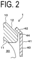
FIG. 2 is an enlarged cross-sectional view illustrating a main part of the thrust bearing according to the embodiment. -
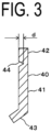
FIG. 3 is a cross-sectional view illustrating a cover according to the first embodiment in a state before being crimped. -
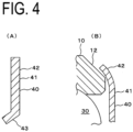
FIG. 4(A) is a cross-sectional view illustrating a cover according to a conventional example in a state before being crimped, andFIG. 4(B) is a cross-sectional view illustrating the cover after being crimped. -
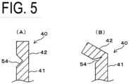
FIG. 5(A) is a cross-sectional view illustrating a cover according to a modification of the first embodiment in a state before being crimped, andFIG. 5(B) is a cross-sectional view illustrating the cover after being crimped. -
FIG. 6(A) is a cross-sectional view illustrating a cover in a thrust bearing according to a second embodiment of the present invention in a state before being crimped, andFIG. 5(B) is a cross-sectional view illustrating the cover after being crimped. -
FIG. 7(A) is a cross-sectional view illustrating a cover according to a modification of the second embodiment in a state before being crimped, andFIG. 7(B) is a cross-sectional view illustrating the cover after being crimped. - A thrust bearing according to one embodiment of the present invention will be described with reference to
FIGS 1 to 4 . Note that in the following description, an "axial direction" indicates a direction of a central axis of the thrust bearing, and a "radial direction" indicates a direction orthogonal to the axial direction. In addition, a "circumferential direction" indicates a direction of rotation about the central axis. Further, terms indicating directions such as "upper" and "lower" are used to indicate the up-down direction inFIG. 1 . -
FIG. 1 is a cross-sectional view illustrating a thrust bearing 1 according to the embodiment. The thrust bearing 1 includes a first bearingwasher 10 and a second bearingwasher 20 disposed to face each other. Thefirst bearing washer 10 and thesecond bearing washer 20 have an annular shape, andraceway grooves first bearing washer 10 and the second bearingwasher 20. - A plurality of
rolling elements 30 are disposed at equal intervals in the circumferential direction at bearing rings having a circular cross section constituted by theraceway grooves rolling elements 30 have a spherical shape, and a distance between adjacentrolling elements 30 is kept constant by a cage (not illustrated). - A
chamfered part 12 is formed over the entire circumference at an axially upper corner part of the outer peripheral surface of thefirst bearing washer 10. In addition, achamfered part 22 is formed over the entire circumference at an axially upper corner part of the outer peripheral surface of thesecond bearing washer 20. A cover (holding member) 40 for covering the outer peripheral surfaces of thefirst bearing washer 10 and the second bearingwasher 20 is attached to thefirst bearing washer 10 and thesecond bearing washer 20. - The
cover 40 has a substantially cylindrical shape, and includes acylindrical part 41 facing the outer peripheral surfaces of thefirst bearing washer 10 and thesecond bearing washer 20, andbent parts cylindrical part 41. The axiallyupper bent part 42 faces thechamfered part 12 of thefirst bearing washer 10, and the axiallylower bent part 43 faces thechamfered part 22 of the second bearingwasher 20. Acircumferential groove 44 is formed at a boundary between thebent part 42 and thecylindrical part 41. - First, the axially
lower bent part 43 of the cylindrically formed component of thecover 40 is formed. In this case, a disk-shaped blank is punched from a flat plate, and the blank is drawn into a cup shape having a tapered part to serve as thebent part 43 at a corner part of the blank. Next, the inside of the tapered part is punched out to form a component of thecover 40 having thebent part 43. - A plurality of
rolling elements 30 held by a cage (not illustrated) are placed in theraceway grooves 21 of the second bearingwasher 20, and the first bearingwasher 10 is placed on therolling elements 30. This assembly is inserted into the component of thecover 40 formed with thebent part 43. As illustrated inFIG. 3 , acircumferential groove 44 is formed along the entire circumference of the inner periphery of the axially upper end part of the component of thecover 40. - The
circumferential groove 44 has a V-shaped cross section, and has a depth equal to or less than half of the thickness of thecylindrical part 41 of thecover 40, and preferably equal to or less than one-third of the thickness of thecylindrical part 41. Then, roll crimping is performed at the outer peripheral surface of the upper part of thecircumferential groove 44 to form thebent part 42. As a result, the first bearingwasher 10 and the second bearingwasher 20 are brought into a state of being inseparable from each other in the axial direction due to thebent parts cover 40. - In the thrust bearing 1 having the above-described configuration, the
circumferential groove 44 is formed over the entire circumference of the inner peripheral surface at the boundary part between thebent part 42 and thecylindrical part 41 of thecover 40, and thus stress is concentrated when thebent part 42 is roll-crimped because the bottom wall thickness of thecircumferential groove 44 is thin, and thecircumferential groove 44 is crushed and deformed such that thecover 40 is bent at thecircumferential groove 44. Then, the roll crimping is completed when the two inner side surfaces of thecircumferential groove 44 having the V-shaped cross section come into close contact with each other. Therefore, as illustrated inFIG. 2 , the cross-sectional shape of thebent part 42 is a linear shape or a shape approximate to the linear shape. - On the other hand, in the conventional thrust bearing having no
circumferential groove 44 as illustrated inFIG. 4(A) , when thebent part 42 is formed by crimping, a stress is uniformly applied to the part to be thebent part 42, and the cross-sectional shape of thebent part 42 becomes a curved shape as illustrated inFIG. 4(B) . This causes a dimensional variation in the gap between thebent part 42 and thefirst bearing washer 10. - As described above, in the thrust bearing 1 of the above first embodiment, the
bent part 42 can be formed into a linear shape or a shape approximate to the linear shape by reducing a curve of thebent part 42 at the time of crimping, and thus the gap between thebent part 42 and the first bearingwasher 10 can be accurately set. - In particular, in the above first embodiment, the
circumferential groove 44 before crimping is formed to have a V-shaped cross section, and the two inner side surfaces of thecircumferential groove 44 are brought into close contact with each other after crimping. Thus, by setting the opening angle of thecircumferential groove 44, the angle formed by thebent part 42 and thecylindrical part 41 can be set, and the gap between the distal end edge of thebent part 42 and thechamfered part 12 of the first bearingwasher 10 can be accurately set. - In addition, in the above first embodiment, the depth of the
circumferential groove 44 is set to half or less of the thickness of thecylindrical part 41 of thecover 40, preferably one-third or less of the thickness of thecylindrical part 41, and thus the strength of thecover 40 is secured, and thefirst bearing washer 10 and thesecond bearing washer 20 can be firmly joined to each other. - In the above first embodiment, the two inner side surfaces of the
circumferential groove 44 are brought into close contact with each other after crimping. However, as illustrated inFIG. 5 , the opening angle of acircumferential groove 54 may be set to be large so that thecircumferential groove 54 has a V-shaped cross section after crimping. Even in this case, the two inner side surfaces of thecircumferential groove 44 come into contact with each other in the vicinity of the intersection point of the two inner side surfaces (in the vicinity of the bottom part of the circumferential groove 44), and the load required for further bending increases. Thus, the angle formed by thebent part 42 and thecylindrical part 41 can be controlled, and the gap between the distal end edge of thebent part 42 and thechamfered part 12 of thefirst bearing washer 10 can be accurately set. - A second embodiment of the present invention will be described with reference to
FIG. 6 . In the second embodiment, the cross-sectional shape of acircumferential groove 64 before crimping is a semi-elliptical shape. In such acircumferential groove 64, when thebent part 42 is formed by crimping, the axial edge parts of the two inner side surfaces of thecircumferential groove 64 are brought into close contact with each other after crimping. Therefore, also in the second embodiment, by setting the interval between the axial edge parts of the inner side surface of thecircumferential groove 64, the angle formed by thebent part 42 and thecylindrical part 41 can be set, and the gap between the distal end edge of thebent part 42 and thechamfered part 12 of thefirst bearing washer 10 can be accurately set. -
FIG. 7 illustrates a modification of the above second embodiment. In this modification, the cross-sectional shape of acircumferential groove 74 before crimping is a semicircular shape. Thecircumferential groove 74 is open even after thebent part 42 is formed by crimping. Note that the cross-sectional shape of thecircumferential groove 74 may be semi-elliptical or U-shaped. - The present invention is not limited to the embodiment described above, and it is possible to make various modifications as described below.
- i) While the
cover 40 is provided at the outer peripheral side of thefirst bearing washer 10 and thesecond bearing washer 20 in the above embodiment, thecover 40 may be provided at the inner peripheral side. In that case, chamfered parts are formed at corner parts of both axial end parts of the inner peripheral surfaces of thefirst bearing washer 10 and thesecond bearing washer 20, and bent parts facing the chamfered parts are formed at both end parts of the cover. - ii) The rolling
elements 30 are not limited to spherical ones, and columnar ones or truncated conical ones can be used. - iii) In the above embodiment, the
raceway grooves first bearing washer 10 and thesecond bearing washer 20. However, a spherical recessed part for supporting the rollingelements 30 may be formed in thesecond bearing washer 20, and the surface of thefirst bearing washer 10 facing the spherical recessed part may be formed to be flat. The same applies to the case where the rollingelements 30 are columnar ones or truncated conical ones. - The present invention can be applied to various thrust bearings such as a thrust bearing for a king pin used in a suspension of an automobile or the like and a bolt with one bearing washer fixed to a head part to reduce torque at the time of fastening.
- 1 Thrust bearing, 10 First bearing washer, 20 Second bearing washer, 11, 21 Raceway groove, 30 Rolling element, 12, 22 Chamfered part, 40 Cover, 41 Cylindrical part, 42, 43 Bent part, 44, 54, 64, 74 Circumferential groove
Claims (14)
- A thrust bearing comprising:a first bearing washer including a raceway groove;a second bearing washer including a raceway groove;a rolling element disposed between the raceway groove of the first bearing washer and the raceway groove of the second bearing washer; anda holding member disposed covering outer peripheral surfaces or inner peripheral surfaces of the first bearing washer and the second bearing washer and holding the first bearing washer and the second bearing washer in an axial direction,the holding member including a cylindrical part facing the outer peripheral surfaces or the inner peripheral surfaces of the first bearing washer and the second bearing washer and a bent part bent over an entire circumference with respect to the cylindrical part at at least one of axial end parts of the cylindrical part, anda chamfered part being formed at a corner part of an outer peripheral surface or an inner peripheral surface of at least one of the first bearing washer or the second bearing washer, the chamfered part and the bent part of the holding member facing each other, whereina circumferential groove is formed at a boundary part between the bent part and the cylindrical part over an entire circumference of an inner peripheral surface or an outer peripheral surface.
- The thrust bearing according to claim 1,
wherein a depth of the circumferential groove is equal to or less than half of a thickness of the cylindrical part of the holding member. - The thrust bearing according to claim 2,
wherein the depth of the circumferential groove is equal to or less than one-third of the thickness of the cylindrical part of the holding member. - The thrust bearing according to any one of claims 1 to 3,
wherein an inner side surface of the circumferential groove at one side in the axial direction and an inner side surface at the other side in the axial direction are at least partially in contact with each other. - The thrust bearing according to any one of claims 1 to 4,
wherein an inner side surface of the circumferential groove at one side in the axial direction and an inner side surface at the other side in the axial direction are entirely in contact with each other. - The thrust bearing according to any one of claims 1 to 3,
wherein the circumferential groove has a substantially V-shaped cross section. - The thrust bearing according to any one of claims 1 to 3,
wherein the circumferential groove has a substantially oval cross-sectional shape, and an end edge of an inner side surface of the circumferential groove at one side in the axial direction and an end edge of the inner side surface at the other side in the axial direction are in contact with each other. - The thrust bearing according to any one of claims 1 to 3,
wherein the circumferential groove has a substantially U-shaped cross section. - A method for manufacturing a thrust bearing including a first bearing washer including a raceway groove, a second bearing washer including a raceway groove, a rolling element disposed between the raceway groove of the first bearing washer and the raceway groove of the second bearing washer, and a holding member disposed covering outer peripheral surfaces or inner peripheral surfaces of the first bearing washer and the second bearing washer and holding the first bearing washer and the second bearing washer in an axial direction,the holding member including a cylindrical part facing the outer peripheral surfaces or the inner peripheral surfaces of the first bearing washer and the second bearing washer and a bent part bent over an entire circumference with respect to the cylindrical part at at least one of axial end parts of the cylindrical part, anda chamfered part being formed at a corner part of an outer peripheral surface or an inner peripheral surface of at least one of the first bearing washer and the second bearing washer, the chamfered part and the bent part of the holding member facing each other, the method comprising:forming the cylindrical part and the bent part into a cylindrical shape having a uniform cross section;forming a circumferential groove over an entire circumference of an inner peripheral surface or an outer peripheral surface at a terminal part of the cylindrical part; andbending the cylindrical part at the circumferential groove to form the bent part by crimping.
- The method for manufacturing a thrust bearing according to claim 9,
wherein in the crimping, an inner side surface of the circumferential groove at one side in the axial direction and an inner side surface at the other side in the axial direction are at least partially brought into contact with each other. - The method for manufacturing a thrust bearing according to claim 9,
wherein an inner side surface of the circumferential groove at one side in the axial direction and an inner side surface at the other side in the axial direction are entirely brought into contact with each other. - The method for manufacturing a thrust bearing according to claim 9,
wherein an inner side surface of the circumferential groove at one side in the axial direction and an inner side surface at the other side in the axial direction are separated from each other such that the circumferential groove after crimping has a substantially V-shaped cross section. - The method for manufacturing a thrust bearing according to claim 9,
wherein the circumferential groove has a substantially semicircular or substantially U-shaped cross section, and an end edge of an inner side surface of the circumferential groove at one side in the axial direction and an end edge of an inner side surface at the other side in the axial direction are brought into contact with each other. - The method for manufacturing a thrust bearing according to claim 9,
wherein the circumferential groove has a substantially semicircular or substantially U-shaped cross section, and an end edge of an inner side surface of the circumferential groove at one side in the axial direction and an end edge of an inner side surface at the other side in the axial direction are separated from each other.
Applications Claiming Priority (2)
| Application Number | Priority Date | Filing Date | Title |
|---|---|---|---|
| JP2022133392A JP7820260B2 (en) | 2022-08-24 | 2022-08-24 | Thrust bearing |
| PCT/JP2023/025273 WO2024042885A1 (en) | 2022-08-24 | 2023-07-07 | Thrust bearing |
Publications (1)
| Publication Number | Publication Date |
|---|---|
| EP4579097A1 true EP4579097A1 (en) | 2025-07-02 |
Family
ID=90013023
Family Applications (1)
| Application Number | Title | Priority Date | Filing Date |
|---|---|---|---|
| EP23857002.2A Pending EP4579097A1 (en) | 2022-08-24 | 2023-07-07 | Thrust bearing |
Country Status (5)
| Country | Link |
|---|---|
| EP (1) | EP4579097A1 (en) |
| JP (1) | JP7820260B2 (en) |
| CN (1) | CN119384562A (en) |
| TW (1) | TW202409443A (en) |
| WO (1) | WO2024042885A1 (en) |
Family Cites Families (10)
| Publication number | Priority date | Publication date | Assignee | Title |
|---|---|---|---|---|
| JP2549161Y2 (en) * | 1990-11-30 | 1997-09-30 | 清原 まさ子 | Non-separable thrust ball bearing |
| JPH084759A (en) | 1994-06-17 | 1996-01-09 | Nippon Seiko Kk | Thrust bearing |
| JP2007309352A (en) | 2006-05-16 | 2007-11-29 | Ntn Corp | Thrust bearing |
| JP2009047239A (en) * | 2007-08-20 | 2009-03-05 | Ntn Corp | Welding retainer and roller bearing |
| JP5431611B1 (en) * | 2013-07-12 | 2014-03-05 | マルミ光機株式会社 | Filter lens holding mechanism in the filter frame |
| WO2015097964A1 (en) * | 2013-12-26 | 2015-07-02 | 株式会社鷺宮製作所 | Caulk structure |
| JP2016023690A (en) | 2014-07-17 | 2016-02-08 | 日本精工株式会社 | Thrust bearing |
| JP6501504B2 (en) * | 2014-11-18 | 2019-04-17 | Ntn株式会社 | Thrust roller bearing cage and method of manufacturing the same |
| JP7270416B2 (en) | 2019-03-05 | 2023-05-10 | Ntn株式会社 | thrust bearing |
| JP7259552B2 (en) | 2019-05-30 | 2023-04-18 | トヨタ紡織株式会社 | deck board |
-
2022
- 2022-08-24 JP JP2022133392A patent/JP7820260B2/en active Active
-
2023
- 2023-07-07 CN CN202380047682.9A patent/CN119384562A/en active Pending
- 2023-07-07 EP EP23857002.2A patent/EP4579097A1/en active Pending
- 2023-07-07 WO PCT/JP2023/025273 patent/WO2024042885A1/en not_active Ceased
- 2023-08-23 TW TW112131586A patent/TW202409443A/en unknown
Also Published As
| Publication number | Publication date |
|---|---|
| TW202409443A (en) | 2024-03-01 |
| JP2024030467A (en) | 2024-03-07 |
| JP7820260B2 (en) | 2026-02-25 |
| CN119384562A (en) | 2025-01-28 |
| WO2024042885A1 (en) | 2024-02-29 |
Similar Documents
| Publication | Publication Date | Title |
|---|---|---|
| US10598218B2 (en) | Angular contact roller bearing and method and device for the assembly thereof | |
| US10655672B2 (en) | Method and device for producing an angular contact roller bearing | |
| US9318924B2 (en) | Rotor mechanism of rotating electrical machine and method of manufacturing same | |
| EP0444754A2 (en) | Bearings | |
| US12320391B2 (en) | External snap ring retainer | |
| EP3176449B1 (en) | Thrust bearing and manufacturing method for same | |
| US6179474B1 (en) | High capacity roller bearing | |
| US10060472B2 (en) | Bearing device and method for manufacturing bearing device | |
| JP2005172059A (en) | Roller bearing | |
| EP3396184B1 (en) | Crossed roller bearing | |
| JP7820260B2 (en) | Thrust bearing | |
| EP3421828B1 (en) | Roller bearing | |
| EP2975278A1 (en) | Rolling bearing and method for manufacturing such a rolling bearing | |
| EP3040569A1 (en) | Method for manufacturing shell-type needle bearing, and manufacturing jig used in manufacture of same | |
| US10670075B2 (en) | Thrust roller bearing | |
| JP7469639B2 (en) | Manufacturing method of retainer for spherical roller bearing | |
| JP7472544B2 (en) | Cylindrical roller bearing with outer ring | |
| US6238097B1 (en) | Sheet-metal cage for roller bearings | |
| US5567059A (en) | Window cage | |
| US10753402B2 (en) | Bearing assembly and bearing cage | |
| WO2024018702A1 (en) | Thrust roller bearing retainer and thrust roller bearing | |
| EP2860414A1 (en) | Conical roller bearing | |
| CN113474566B (en) | Rollers and roller bearings with cages | |
| EP3106690A1 (en) | Self-aligning roller bearing and assembly method for the same | |
| JP2015203438A (en) | Method for manufacturing waveform holder and waveform holder |
Legal Events
| Date | Code | Title | Description |
|---|---|---|---|
| STAA | Information on the status of an ep patent application or granted ep patent |
Free format text: STATUS: THE INTERNATIONAL PUBLICATION HAS BEEN MADE |
|
| PUAI | Public reference made under article 153(3) epc to a published international application that has entered the european phase |
Free format text: ORIGINAL CODE: 0009012 |
|
| STAA | Information on the status of an ep patent application or granted ep patent |
Free format text: STATUS: REQUEST FOR EXAMINATION WAS MADE |
|
| 17P | Request for examination filed |
Effective date: 20250203 |
|
| AK | Designated contracting states |
Kind code of ref document: A1 Designated state(s): AL AT BE BG CH CY CZ DE DK EE ES FI FR GB GR HR HU IE IS IT LI LT LU LV MC ME MK MT NL NO PL PT RO RS SE SI SK SM TR |
|
| DAV | Request for validation of the european patent (deleted) | ||
| DAX | Request for extension of the european patent (deleted) | ||
| P01 | Opt-out of the competence of the unified patent court (upc) registered |
Free format text: CASE NUMBER: UPC_APP_0003838_4579097/2026 Effective date: 20260203 |