EP4579081A1 - State monitoring system and state monitoring method - Google Patents
State monitoring system and state monitoring method Download PDFInfo
- Publication number
- EP4579081A1 EP4579081A1 EP23872052.8A EP23872052A EP4579081A1 EP 4579081 A1 EP4579081 A1 EP 4579081A1 EP 23872052 A EP23872052 A EP 23872052A EP 4579081 A1 EP4579081 A1 EP 4579081A1
- Authority
- EP
- European Patent Office
- Prior art keywords
- parameter
- compressor
- life consumption
- valve
- life
- Prior art date
- Legal status (The legal status is an assumption and is not a legal conclusion. Google has not performed a legal analysis and makes no representation as to the accuracy of the status listed.)
- Pending
Links
Images

Classifications
-
- F—MECHANICAL ENGINEERING; LIGHTING; HEATING; WEAPONS; BLASTING
- F04—POSITIVE - DISPLACEMENT MACHINES FOR LIQUIDS; PUMPS FOR LIQUIDS OR ELASTIC FLUIDS
- F04B—POSITIVE-DISPLACEMENT MACHINES FOR LIQUIDS; PUMPS
- F04B49/00—Control, e.g. of pump delivery, or pump pressure of, or safety measures for, machines, pumps, or pumping installations, not otherwise provided for, or of interest apart from, groups F04B1/00 - F04B47/00
- F04B49/10—Other safety measures
-
- F—MECHANICAL ENGINEERING; LIGHTING; HEATING; WEAPONS; BLASTING
- F04—POSITIVE - DISPLACEMENT MACHINES FOR LIQUIDS; PUMPS FOR LIQUIDS OR ELASTIC FLUIDS
- F04B—POSITIVE-DISPLACEMENT MACHINES FOR LIQUIDS; PUMPS
- F04B49/00—Control, e.g. of pump delivery, or pump pressure of, or safety measures for, machines, pumps, or pumping installations, not otherwise provided for, or of interest apart from, groups F04B1/00 - F04B47/00
- F04B49/06—Control using electricity
- F04B49/065—Control using electricity and making use of computers
-
- F—MECHANICAL ENGINEERING; LIGHTING; HEATING; WEAPONS; BLASTING
- F04—POSITIVE - DISPLACEMENT MACHINES FOR LIQUIDS; PUMPS FOR LIQUIDS OR ELASTIC FLUIDS
- F04B—POSITIVE-DISPLACEMENT MACHINES FOR LIQUIDS; PUMPS
- F04B51/00—Testing machines, pumps, or pumping installations
-
- G—PHYSICS
- G01—MEASURING; TESTING
- G01M—TESTING STATIC OR DYNAMIC BALANCE OF MACHINES OR STRUCTURES; TESTING OF STRUCTURES OR APPARATUS, NOT OTHERWISE PROVIDED FOR
- G01M13/00—Testing of machine parts
- G01M13/003—Machine valves
-
- G—PHYSICS
- G01—MEASURING; TESTING
- G01M—TESTING STATIC OR DYNAMIC BALANCE OF MACHINES OR STRUCTURES; TESTING OF STRUCTURES OR APPARATUS, NOT OTHERWISE PROVIDED FOR
- G01M99/00—Subject matter not provided for in other groups of this subclass
-
- F—MECHANICAL ENGINEERING; LIGHTING; HEATING; WEAPONS; BLASTING
- F04—POSITIVE - DISPLACEMENT MACHINES FOR LIQUIDS; PUMPS FOR LIQUIDS OR ELASTIC FLUIDS
- F04B—POSITIVE-DISPLACEMENT MACHINES FOR LIQUIDS; PUMPS
- F04B2201/00—Pump parameters
- F04B2201/12—Parameters of driving or driven means
- F04B2201/1201—Rotational speed of the axis
-
- F—MECHANICAL ENGINEERING; LIGHTING; HEATING; WEAPONS; BLASTING
- F04—POSITIVE - DISPLACEMENT MACHINES FOR LIQUIDS; PUMPS FOR LIQUIDS OR ELASTIC FLUIDS
- F04B—POSITIVE-DISPLACEMENT MACHINES FOR LIQUIDS; PUMPS
- F04B2203/00—Motor parameters
- F04B2203/02—Motor parameters of rotating electric motors
- F04B2203/0208—Power
-
- F—MECHANICAL ENGINEERING; LIGHTING; HEATING; WEAPONS; BLASTING
- F04—POSITIVE - DISPLACEMENT MACHINES FOR LIQUIDS; PUMPS FOR LIQUIDS OR ELASTIC FLUIDS
- F04B—POSITIVE-DISPLACEMENT MACHINES FOR LIQUIDS; PUMPS
- F04B2203/00—Motor parameters
- F04B2203/02—Motor parameters of rotating electric motors
- F04B2203/0209—Rotational speed
Definitions
- the present disclosure relates to a condition monitoring system and a condition monitoring method.
- a pump for pumping a liquid or a compressor for compressing a medium such as a gas is known.
- components deteriorate to some extent as an operating time passes. If the deterioration of the components progresses, it may lead to a breakdown or a malfunction, which may cause a problem in operation of the compressor. Therefore, it is important to prevent such breakdown or malfunction by performing maintenance such as replacement or repair of the components at a predetermined timing.
- Patent Document 1 discloses a compressor that can calculate maintenance implementation time (maintenance cycle) of a compressor body on the basis of operating conditions of the compressor (a temperature of the compressor, a pressure of a compressed fluid, and the like).
- Patent Document 1 JP6306740B
- valves operated at a timing of suction and discharge of a fluid to be compressed are important parts which, if they are broken or malfunction, will cause major problems in operation of the compressor.
- a life consumption of the important part such as the valve serves as an effective index.
- the life consumption of the valve of the compressor can be expressed as a function of the number of times the valve is opened and closed (the number of collisions). The number of times the valve is opened and closed can be obtained using a rotation speed and an operating time of the compressor.
- the life of the valve of the compressor consumed by a single opening and closing also differs depending on a collision speed, a collision posture, etc., of the valve, and therefore it is difficult to accurately calculate the life consumption of the valve only from the rotation speed and the operating time of the compressor.
- At least one embodiment of the present disclosure was made in view of the above issue, and an object of at least one embodiment of the present disclosure is to provide a condition monitoring system and a condition monitoring method, which are capable of accurately assessing the life consumption of the valve.
- a condition monitoring system for a valve of a compressor, including: a parameter acquisition unit for acquiring at least one first parameter indicating an operating condition of the compressor and a second parameter correlated with a degree of superheat of a fluid flowing into the compressor; a factor calculation unit for calculating, from a map defining a relationship among the first parameter, the second parameter, and a severity factor indicating a life consumption level of the valve, the severity factor corresponding to the first parameter and the second parameter; and a calculation unit for calculating an accumulated life consumption by accumulating a life consumption of the valve in a unit period, which is calculated using at least a length of the unit period, a rotation speed of the compressor for each unit period, and the severity factor.
- a condition monitoring method for a valve of a compressor, including: a step of acquiring at least one first parameter indicating an operating condition of the compressor and a second parameter correlated with a degree of superheat of a fluid flowing into the compressor; a step of calculating, from a map defining a relationship among the first parameter, the second parameter, and a severity factor indicating a life consumption level of the valve, the severity factor corresponding to the first parameter and the second parameter; and a step of calculating an accumulated life consumption by accumulating a life consumption of the valve in a unit period, which is calculated using at least a length of the unit period, a rotation speed of the compressor for each unit period, and the severity factor.
- condition monitoring system and a condition monitoring method which are capable of accurately assessing a life consumption of a valve.
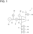
- FIG. 1 is a diagram showing a schematic configuration of the compressor 1.
- the compressor 1 includes a compressor body 2, a suction line 4 located upstream of the compressor body 2, and a discharge line 6 located downstream of the compressor body 2.
- the compressor body 2 is a reciprocating compressor and is provided with a motor 8 as a power source.
- the motor 8 is connected to the compressor body 2 via a drive shaft 10.
- the motor 8 is driven by power supplied from a power source 12 (for example, a commercial power source), and the driving force is transmitted to the compressor body 2 via the drive shaft 10.
- a fluid air, refrigerant, etc.
- the fluid compressed in the compressor body 2 is discharged toward a supply destination (not shown) via the discharge line 6.
- the suction line 4 is provided with a suction pressure sensor 14 for detecting a pressure (hereinafter, referred to as a "suction pressure ps" as appropriate) of the fluid supplied to the compressor body 2, a suction temperature sensor 15 for detecting a temperature (hereinafter, referred to as a “suction temperature Ts" as appropriate) of the fluid supplied to the compressor body 2, and a superheat degree sensor 16 for detecting a superheat degree Sh of the fluid supplied to the compressor body 2.
- the discharge line 6 is provided with a discharge pressure sensor 18 for detecting a pressure (hereinafter, referred to as a "discharge pressure pd" as appropriate) of the fluid discharged from the compressor body 2.
- a power supply line 13 for supplying power from the power source 12 to the compressor body 2 is provided with a power sensor 20 for detecting power consumption Pw or a power frequency Pf of the compressor body 2.
- the compressor body 2 is also provided with a rotation speed sensor 22 for detecting a rotation speed f of the compressor body 2.
- a detection result of each of these sensors can be output as an electrical signal, and is acquired by the condition monitoring system 100 described later and is used for various kinds of calculation processing (if there are detection results that are not used by the condition monitoring system 100, the sensors corresponding to those detection results can be omitted as appropriate).
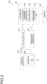
- FIG. 2 is a block diagram showing a configuration of the condition monitoring system 100 according to an embodiment.
- the condition monitoring system 100 includes, for example, a Central Processing Unit (CPU), a Random Access Memory (RAM), a Read Only Memory (ROM), a computer-readable storage medium, and the like. Then, a series of processes for realizing various functions is stored in the storage medium, etc., in the form of a program, as an example.
- the CPU reads the program out to the RAM, etc., and executes processing/calculation processing of information, thereby realizing the various functions.
- a configuration where the program is installed in the ROM or another storage medium in advance, a configuration where the program is provided in a state of being stored in the computer-readable storage medium, a configuration where the program is distributed via a wired or wireless communication means, etc., may be applied.
- the computer-readable storage medium is a magnetic disk, a magneto-optical disk, a CD-ROM, a DVD-ROM, a semiconductor memory, etc.
- the condition monitoring system 100 includes a parameter acquisition unit 102, a factor calculation unit 104, a storage unit 106, a rotation speed acquisition unit 108, a calculation unit 110, and an output unit 112.
- the parameter acquisition unit 102 is configured to acquire a first parameter P1 and a second parameter P2.
- the first parameter P1 is at least one parameter indicating an operating condition of the compressor 1.
- the first parameter P1 includes at least one of the suction pressure ps detected by the suction pressure sensor 14, the discharge pressure pd detected by the discharge pressure sensor 18, and the power consumption Pw or the power frequency Pf detected by the power sensor 20.
- the second parameter P2 is a parameter correlated with the degree of superheat of the fluid flowing into the compressor 1.
- the second parameter P2 includes at least one of the superheat degree Sh detected by the superheat degree sensor 16 or the suction temperature Ts detected by the suction temperature sensor 15.
- the parameter acquisition unit 102 acquires each parameter at a sampling frequency dt [min].
- a numerical range of the sampling frequency dt is not limited, but is set so that each parameter can continuously be acquired in an appropriate period (for example, not less than one year) in order to assess the life of the compressor 1, for example.
- the suction pressure ps and the discharge pressure pd are selected as the first parameter P1 and the superheat degree Sh is selected as the second parameter P2, but other combinations are also possible.
- the suction pressure ps and the power consumption Pw may be selected as the first parameter P1
- the suction temperature Ts may be selected as the second parameter P2.
- the discharge pressure pd and the power consumption Pw (or the power frequency Pf) may be selected as the first parameter P1
- the suction temperature Ts may be selected as the second parameter P2.
- the factor calculation unit 104 is configured to calculate a severity factor S on the basis of the first parameter P1 and the second parameter P2 acquired by the parameter acquisition unit 102.
- the severity factor S is an assessment index corresponding to a life consumption of a valve of the compressor 1, and is calculated on the basis of both the first parameter P1 and the second parameter P2.
- the factor calculation unit 104 calculates the severity factor S by using a map M indicating a relationship among the first parameter P1, the second parameter P2, and the severity factor S.
- the map M is constructed in advance by an experimental, empirical or simulation method to indicate the relationship among the first parameter P1, the second parameter P2, and the severity factor S, and is readably stored in the storage unit 106 such as a memory.
- the factor calculation unit 104 acquires the map M by accessing the storage unit 106 and obtains, on the basis of the map M, the severity factor S corresponding to the first parameter P 1 and the second parameter P 2 acquired by the parameter acquisition unit 102.
- the calculation of the severity factor S in the factor calculation unit 104 is thus performed by using such map M, in consideration of non-linearity of the degree of superheat of the fluid flowing into the compressor 1 with respect to the life consumption.
- the rotation speed acquisition unit 108 is configured to acquire the rotation speed f of the compressor body 2.
- the rotation speed f can be acquired as a detected value of the rotation speed sensor 22 as described above.
- the calculation unit 110 is configured to perform various calculations for monitoring the condition of the compressor 1, on the basis of the severity factor S calculated by the factor calculation unit 104 and the rotation speed f acquired by the rotation speed acquisition unit 108.
- the calculation unit 110 includes a plurality of functional blocks according to calculation contents thereof, and specifically includes an accumulated life consumption calculation unit 114, a life prediction unit 116, and a maintenance timing recommendation unit 118.
- the accumulated life consumption calculation unit 114 is configured to calculate an accumulated life consumption L in a preset unit period.
- the accumulated life consumption L is obtained by accumulating the life consumption of the valve of the compressor body 2 in the unit period, which is calculated using at least the rotation speed f acquired by the rotation speed acquisition unit 108 and the severity factor S calculated by the factor calculation unit 104, in the unit period.
- the life prediction unit 116 is configured to predict a remaining life of the valve of the compressor 1 from a past trend of the accumulated life consumption L.
- the accumulated life consumption L is sequentially calculated by the accumulated life consumption calculation unit 114 described above.
- the life prediction unit 116 identifies the past trend of the accumulated life consumption L on the basis of a time transition of the accumulated life consumption L calculated sequentially, and predicts the remaining life on the basis of the past trend. For example, a transition of the future accumulated life consumption L is estimated from the past trend, and a period until the accumulated life consumption L estimated reaches a certain threshold is predicted as the remaining life.
- the maintenance timing recommendation unit 118 identifies the past trend of the accumulated life consumption L on the basis of the time transition of the accumulated life consumption L calculated sequentially, and predicts the recommended timing for next maintenance on the basis of the past trend. For example, the transition of the future accumulated life consumption L is estimated from the past trend, and a timing at which the accumulated life consumption L estimated reaches a certain threshold is predicted as the recommended timing for next maintenance.
- the output unit 112 is configured to output a calculation result of the calculation unit 110.
- the aforementioned accumulated life consumption L, remaining life, and recommended timing for next maintenance, which are calculated by the calculation unit 110, are output by the output unit 112 and recognized by an operator of the condition monitoring system 100.
- the accumulated life consumption L or the remaining life is displayed in a manner that can be recognized by the operator using a display device such as a display.
- the operator may be notified that the recommended timing for next maintenance has arrived, for example, by an alarm or display.
- the factor calculation unit 104 acquires the map M by accessing the storage unit 106 (step S2).
- the map M is stored in advance in the storage unit 106, and defines the relationship among the first parameter P1, the second parameter P2, and the severity factor S.
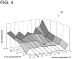
- FIG. 4 is an example of the map M acquired in step S2 of FIG. 3 .
- the map M is shown as a three-dimensional map in which the first parameter P1 is on the X-axis, the second parameter P2 is on the Y-axis, and the severity factor S is on the Z-axis.
- the first parameter P1 and the second parameter P2 are shown one-dimensionally on the X-axis and the Y-axis, respectively.
- the map M may be prepared as a multidimensional map with not less than three dimensions.
- step S3 the factor calculation unit 104 calculates the severity factor S (step S3).
- the corresponding severity factor S is calculated by applying the first parameter P1 and the second parameter P acquired in step S1 to the map M acquired in step S2.
- the severity factor S has a nonlinear behavior with respect to the first parameter P1 and the second parameter P2, but as described above with reference to FIG. 4 , by preparing the severity factor S as the map M, it is possible to uniquely obtain the severity factor S corresponding to the first parameter P1 and the second parameter P2.
- the rotation speed acquisition unit 108 acquires the rotation speed f of the compressor body 2 (step S4).
- the rotation speed acquisition unit 108 can acquire the rotation speed f on the basis of the detection result of the rotation speed sensor 22.
- FIG. 5 is a graph showing the time transition of the accumulated life consumption L calculated in step S5 of FIG. 3 .
- the accumulated life consumption L calculated by the above (1) gradually increases as the operating time of the compressor 1 progresses.
- FIG. 5 also shows, as a comparative example, a time transition of an accumulated life consumption L' calculated on the basis of a standard operating condition.
- the accumulated life consumption L' is calculated under a relatively severe operating condition, and is expressed, for example, as a linear function increasing at a constant rate of change with respect to time.
- the accumulated life consumption L calculated in step S5 is lower than the accumulated life consumption L' based on the standard operating condition.
- the accumulated life consumption L is calculated in consideration of the nonlinear behavior of the severity factor S with respect to the second parameter P2, the accumulated life consumption L does not include an excessive margin compared to the accumulated life consumption L' based on the standard operating condition and the condition of the compressor 1 is accurately assessed.
- the life prediction unit 116 predicts the remaining life of the valve of the compressor 1 on the basis of the accumulated life consumption L calculated in step S5 (step S6).
- the remaining life is predicted by identifying the past trend from the time transition of the accumulated life consumption L, and estimating the future accumulated life consumption L from the past trend.
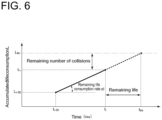
- FIG. 6 is a graph showing how to estimate the future accumulated life consumption L from the past trend of the accumulated life consumption L.
- the horizontal axis represents time
- data is acquired and calculated on a daily basis
- the accumulated life consumption L for 30 days from time t i-30 to time t i (present) is obtained by repeating steps S1 to S5 described above.
- the life prediction unit 116 approximates the past trend in the above period with a linear function, and calculates a linear coefficient ⁇ i as the life consumption rate in the above period by the following equation.
- L i L i ⁇ L i ⁇ 30 t i ⁇ t i ⁇ 30
- L i is an accumulated life consumption corresponding to the time t i .
- the maintenance timing recommendation unit 118 calculates the recommended timing for next maintenance (step S7).
- a recommended timing t m for next maintenance is obtained by the following equation, for example, by subtracting the predetermined period t n from the life t thr calculated in step S6.
- t m t thr ⁇ t n
- the recommended timing t m is obtained as a timing that can ensure a margin of the predetermined period t n , from the life t thr .
- the output unit 112 outputs the calculation result (step S8).
- the calculation result output in step S8 includes, for example, at least one of the accumulated life consumption L calculated in step S5, the life t thr calculated in step S6, and the recommended timing t m for next maintenance calculated in step S7.
- step S8 The above step corresponding to the calculation result which is not included in the output result in step S8 can be omitted as appropriate.
- the severity factor which serves as the assessment index corresponding to the life consumption of the valve of the compressor is calculated on the basis of both the first parameter indicating the operating condition and the second parameter correlated with the degree of superheat of the fluid flowing into the compressor. Since the calculation of the severity factor is performed by using the map indicating the relationship among the first parameter, the second parameter, and the severity factor, the calculation of the severity factor is performed in consideration of the non-linearity of the degree of superheat of the fluid flowing into the compressor with respect to the life consumption. By calculating the accumulated life consumption which is the accumulated value of such severity factor, the condition of the valve of the compressor can be monitored accurately.
- the severity factor which serves as the assessment index corresponding to the life consumption of the valve of the compressor is calculated on the basis of both the first parameter indicating the operating condition and the second parameter correlated with the degree of superheat of the fluid flowing into the compressor. Since the calculation of the severity factor is performed by using the map indicating the relationship among the first parameter, the second parameter, and the severity factor, the calculation of the severity factor is performed in consideration of the non-linearity of the degree of superheat of the fluid flowing into the compressor with respect to the life consumption. By calculating the accumulated life consumption which is the accumulated value of such severity factor, the condition of the valve of the compressor can be monitored accurately.
Landscapes
- Engineering & Computer Science (AREA)
- Mechanical Engineering (AREA)
- General Engineering & Computer Science (AREA)
- Physics & Mathematics (AREA)
- General Physics & Mathematics (AREA)
- Computer Hardware Design (AREA)
- Control Of Positive-Displacement Pumps (AREA)
- Testing Of Devices, Machine Parts, Or Other Structures Thereof (AREA)
Abstract
Description
- The present disclosure relates to a condition monitoring system and a condition monitoring method.
- For example, as a rotating machinery driven by power from a power source such as a motor, a pump for pumping a liquid or a compressor for compressing a medium such as a gas is known. In this type of compressor, components deteriorate to some extent as an operating time passes. If the deterioration of the components progresses, it may lead to a breakdown or a malfunction, which may cause a problem in operation of the compressor. Therefore, it is important to prevent such breakdown or malfunction by performing maintenance such as replacement or repair of the components at a predetermined timing.
- The timing at which the maintenance of the compressor is performed can vary depending on an operation form or an external environment of the compressor. For example,
Patent Document 1 discloses a compressor that can calculate maintenance implementation time (maintenance cycle) of a compressor body on the basis of operating conditions of the compressor (a temperature of the compressor, a pressure of a compressed fluid, and the like). - Patent Document 1:
JP6306740B - In a compressor, valves operated at a timing of suction and discharge of a fluid to be compressed are important parts which, if they are broken or malfunction, will cause major problems in operation of the compressor. In assessment of a maintenance timing of the compressor, a life consumption of the important part such as the valve serves as an effective index.
- The life consumption of the valve of the compressor can be expressed as a function of the number of times the valve is opened and closed (the number of collisions). The number of times the valve is opened and closed can be obtained using a rotation speed and an operating time of the compressor. However, the life of the valve of the compressor consumed by a single opening and closing also differs depending on a collision speed, a collision posture, etc., of the valve, and therefore it is difficult to accurately calculate the life consumption of the valve only from the rotation speed and the operating time of the compressor.
- In addition, the operating conditions of the compressor influence the collision speed, the collision posture, etc., of the valve of the compressor. Therefore, in order to accurately calculate the life consumption of the valve, it is effective to take the operating conditions of the compressor into consideration. According to the findings of the present inventors, it was found that a correlation between the operating conditions of the compressor and the life consumption of the valve varies nonlinearly depending on the degree of superheat of a fluid flowing into the compressor, and even if the operating conditions are the same, the life consumption of the valve is not constant if the degree of superheat of the fluid flowing into the compressor is different. In
Patent Document 1 described above, a substantial life assessment is performed by calculating the maintenance timing of the compressor only by the operating conditions, but since the degree of superheat of the fluid flowing into the compressor is not taken into consideration, accurate assessment cannot be performed. - At least one embodiment of the present disclosure was made in view of the above issue, and an object of at least one embodiment of the present disclosure is to provide a condition monitoring system and a condition monitoring method, which are capable of accurately assessing the life consumption of the valve.
- In order to solve the above-described problems, a condition monitoring system according to at least one embodiment of the present disclosure is a condition monitoring system for a valve of a compressor, including: a parameter acquisition unit for acquiring at least one first parameter indicating an operating condition of the compressor and a second parameter correlated with a degree of superheat of a fluid flowing into the compressor; a factor calculation unit for calculating, from a map defining a relationship among the first parameter, the second parameter, and a severity factor indicating a life consumption level of the valve, the severity factor corresponding to the first parameter and the second parameter; and a calculation unit for calculating an accumulated life consumption by accumulating a life consumption of the valve in a unit period, which is calculated using at least a length of the unit period, a rotation speed of the compressor for each unit period, and the severity factor.
- In order to solve the above-described problems, a condition monitoring method according to at least one embodiment of the present disclosure is a condition monitoring method for a valve of a compressor, including: a step of acquiring at least one first parameter indicating an operating condition of the compressor and a second parameter correlated with a degree of superheat of a fluid flowing into the compressor; a step of calculating, from a map defining a relationship among the first parameter, the second parameter, and a severity factor indicating a life consumption level of the valve, the severity factor corresponding to the first parameter and the second parameter; and a step of calculating an accumulated life consumption by accumulating a life consumption of the valve in a unit period, which is calculated using at least a length of the unit period, a rotation speed of the compressor for each unit period, and the severity factor.
- According to at least one embodiment of the present disclosure, it is possible to provide a condition monitoring system and a condition monitoring method, which are capable of accurately assessing a life consumption of a valve.
-
-
FIG. 1 is a diagram showing a schematic configuration of a compressor. -
FIG. 2 is a block diagram showing a configuration of a condition monitoring system according to an embodiment. -
FIG. 3 is a flowchart showing a condition monitoring method according to an embodiment. -
FIG. 4 is an example of a map acquired in step S2 ofFIG. 3 . -
FIG. 5 is a graph showing a time transition of an accumulated life consumption calculated in step S5 ofFIG. 3 . -
FIG. 6 is a graph showing how to estimate a future accumulated life consumption from a past trend. - Some embodiments of the present invention will be described below with reference to the accompanying drawings. It is intended, however, that unless particularly identified, dimensions, materials, shapes, relative positions and the like of components described or shown in the drawings as the embodiments shall be interpreted as illustrative only and not intended to limit the scope of the present invention.
- First, a
compressor 1 to be monitored by acondition monitoring system 100 according to at least one embodiment of the present disclosure will be described with reference toFIG. 1. FIG. 1 is a diagram showing a schematic configuration of thecompressor 1. - The
compressor 1 includes acompressor body 2, asuction line 4 located upstream of thecompressor body 2, and adischarge line 6 located downstream of thecompressor body 2. Thecompressor body 2 is a reciprocating compressor and is provided with amotor 8 as a power source. Themotor 8 is connected to thecompressor body 2 via adrive shaft 10. Themotor 8 is driven by power supplied from a power source 12 (for example, a commercial power source), and the driving force is transmitted to thecompressor body 2 via thedrive shaft 10. When thecompressor body 2 is driven, a fluid (air, refrigerant, etc.) is introduced into thecompressor body 2 from a fluid supply source (not shown) via thesuction line 4 and compressed in thecompressor body 2. The fluid compressed in thecompressor body 2 is discharged toward a supply destination (not shown) via thedischarge line 6. - The
suction line 4 is provided with asuction pressure sensor 14 for detecting a pressure (hereinafter, referred to as a "suction pressure ps" as appropriate) of the fluid supplied to thecompressor body 2, asuction temperature sensor 15 for detecting a temperature (hereinafter, referred to as a "suction temperature Ts" as appropriate) of the fluid supplied to thecompressor body 2, and asuperheat degree sensor 16 for detecting a superheat degree Sh of the fluid supplied to thecompressor body 2. Thedischarge line 6 is provided with adischarge pressure sensor 18 for detecting a pressure (hereinafter, referred to as a "discharge pressure pd" as appropriate) of the fluid discharged from thecompressor body 2. Apower supply line 13 for supplying power from thepower source 12 to thecompressor body 2 is provided with apower sensor 20 for detecting power consumption Pw or a power frequency Pf of thecompressor body 2. Thecompressor body 2 is also provided with arotation speed sensor 22 for detecting a rotation speed f of thecompressor body 2. - A detection result of each of these sensors can be output as an electrical signal, and is acquired by the
condition monitoring system 100 described later and is used for various kinds of calculation processing (if there are detection results that are not used by thecondition monitoring system 100, the sensors corresponding to those detection results can be omitted as appropriate). - Next, the
condition monitoring system 100 for monitoring the condition of thecompressor 1 having the above configuration will be described.FIG. 2 is a block diagram showing a configuration of thecondition monitoring system 100 according to an embodiment. - The
condition monitoring system 100 includes, for example, a Central Processing Unit (CPU), a Random Access Memory (RAM), a Read Only Memory (ROM), a computer-readable storage medium, and the like. Then, a series of processes for realizing various functions is stored in the storage medium, etc., in the form of a program, as an example. The CPU reads the program out to the RAM, etc., and executes processing/calculation processing of information, thereby realizing the various functions. A configuration where the program is installed in the ROM or another storage medium in advance, a configuration where the program is provided in a state of being stored in the computer-readable storage medium, a configuration where the program is distributed via a wired or wireless communication means, etc., may be applied. The computer-readable storage medium is a magnetic disk, a magneto-optical disk, a CD-ROM, a DVD-ROM, a semiconductor memory, etc. - The
condition monitoring system 100 includes aparameter acquisition unit 102, afactor calculation unit 104, astorage unit 106, a rotationspeed acquisition unit 108, acalculation unit 110, and anoutput unit 112. - The
parameter acquisition unit 102 is configured to acquire a first parameter P1 and a second parameter P2. The first parameter P1 is at least one parameter indicating an operating condition of thecompressor 1. In the present embodiment, the first parameter P1 includes at least one of the suction pressure ps detected by thesuction pressure sensor 14, the discharge pressure pd detected by thedischarge pressure sensor 18, and the power consumption Pw or the power frequency Pf detected by thepower sensor 20. Further, the second parameter P2 is a parameter correlated with the degree of superheat of the fluid flowing into thecompressor 1. In the present embodiment, the second parameter P2 includes at least one of the superheat degree Sh detected by thesuperheat degree sensor 16 or the suction temperature Ts detected by thesuction temperature sensor 15. - The
parameter acquisition unit 102 acquires each parameter at a sampling frequency dt [min]. A numerical range of the sampling frequency dt is not limited, but is set so that each parameter can continuously be acquired in an appropriate period (for example, not less than one year) in order to assess the life of thecompressor 1, for example. - Further, in the following embodiment, as described above, a case will be exemplified in which the suction pressure ps and the discharge pressure pd are selected as the first parameter P1 and the superheat degree Sh is selected as the second parameter P2, but other combinations are also possible. For example, the suction pressure ps and the power consumption Pw may be selected as the first parameter P1, and the suction temperature Ts may be selected as the second parameter P2. Further, the discharge pressure pd and the power consumption Pw (or the power frequency Pf) may be selected as the first parameter P1, and the suction temperature Ts may be selected as the second parameter P2.
- The
factor calculation unit 104 is configured to calculate a severity factor S on the basis of the first parameter P1 and the second parameter P2 acquired by theparameter acquisition unit 102. The severity factor S is an assessment index corresponding to a life consumption of a valve of thecompressor 1, and is calculated on the basis of both the first parameter P1 and the second parameter P2. - The
factor calculation unit 104 calculates the severity factor S by using a map M indicating a relationship among the first parameter P1, the second parameter P2, and the severity factor S. The map M is constructed in advance by an experimental, empirical or simulation method to indicate the relationship among the first parameter P1, the second parameter P2, and the severity factor S, and is readably stored in thestorage unit 106 such as a memory. Thefactor calculation unit 104 acquires the map M by accessing thestorage unit 106 and obtains, on the basis of the map M, the severity factor S corresponding to thefirst parameter P 1 and thesecond parameter P 2 acquired by theparameter acquisition unit 102. The calculation of the severity factor S in thefactor calculation unit 104 is thus performed by using such map M, in consideration of non-linearity of the degree of superheat of the fluid flowing into thecompressor 1 with respect to the life consumption. - The rotation
speed acquisition unit 108 is configured to acquire the rotation speed f of thecompressor body 2. The rotation speed f can be acquired as a detected value of therotation speed sensor 22 as described above. - The
calculation unit 110 is configured to perform various calculations for monitoring the condition of thecompressor 1, on the basis of the severity factor S calculated by thefactor calculation unit 104 and the rotation speed f acquired by the rotationspeed acquisition unit 108. Thecalculation unit 110 includes a plurality of functional blocks according to calculation contents thereof, and specifically includes an accumulated lifeconsumption calculation unit 114, alife prediction unit 116, and a maintenancetiming recommendation unit 118. - The accumulated life
consumption calculation unit 114 is configured to calculate an accumulated life consumption L in a preset unit period. The accumulated life consumption L is obtained by accumulating the life consumption of the valve of thecompressor body 2 in the unit period, which is calculated using at least the rotation speed f acquired by the rotationspeed acquisition unit 108 and the severity factor S calculated by thefactor calculation unit 104, in the unit period. - The
life prediction unit 116 is configured to predict a remaining life of the valve of thecompressor 1 from a past trend of the accumulated life consumption L. The accumulated life consumption L is sequentially calculated by the accumulated lifeconsumption calculation unit 114 described above. Thelife prediction unit 116 identifies the past trend of the accumulated life consumption L on the basis of a time transition of the accumulated life consumption L calculated sequentially, and predicts the remaining life on the basis of the past trend. For example, a transition of the future accumulated life consumption L is estimated from the past trend, and a period until the accumulated life consumption L estimated reaches a certain threshold is predicted as the remaining life. - The maintenance
timing recommendation unit 118 is configured to calculate a recommended timing for next maintenance of thecompressor 1 to be monitored. The recommended timing for next maintenance is obtained, for example, by subtracting a predetermined period tn as a margin from a life tthr calculated by thelife prediction unit 116. Whereby, it is possible to prevent a malfunction or a breakdown by recommending the next maintenance before a timing at which a possibility of a malfunction or a breakdown actually occurring in thecompressor 1 increases due to reaching the end of the life tthr. - Further, as with the
life prediction unit 116, the maintenancetiming recommendation unit 118 identifies the past trend of the accumulated life consumption L on the basis of the time transition of the accumulated life consumption L calculated sequentially, and predicts the recommended timing for next maintenance on the basis of the past trend. For example, the transition of the future accumulated life consumption L is estimated from the past trend, and a timing at which the accumulated life consumption L estimated reaches a certain threshold is predicted as the recommended timing for next maintenance. - The
output unit 112 is configured to output a calculation result of thecalculation unit 110. The aforementioned accumulated life consumption L, remaining life, and recommended timing for next maintenance, which are calculated by thecalculation unit 110, are output by theoutput unit 112 and recognized by an operator of thecondition monitoring system 100. For example, the accumulated life consumption L or the remaining life is displayed in a manner that can be recognized by the operator using a display device such as a display. In addition, when the recommended timing for next maintenance arrives, the operator may be notified that the recommended timing for next maintenance has arrived, for example, by an alarm or display. - Next, a condition monitoring method implemented by the
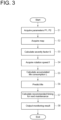
condition monitoring system 100 having the above configuration will be described.FIG. 3 is a flowchart showing the condition monitoring method according to an embodiment. - First, the
parameter acquisition unit 102 acquires the first parameter P1 and the second parameter P2 (step S1). The first parameter P1 can optionally be selected from at least one parameter regarding the operating condition of thecompressor 1. However, as an example, in the present embodiment, a case will be described in which the suction pressure ps detected by thesuction pressure sensor 14 and the discharge pressure pd detected by thedischarge pressure sensor 18 are selected as the first parameter P1. Further, the second parameter P2 can optionally be selected from a parameter correlated with the degree of superheat of the fluid flowing into thecompressor body 2. However, as an example, in the present embodiment, a case will be described in which the superheat degree Sh detected by thesuperheat degree sensor 16 is selected as the second parameter P2. - Next, the
factor calculation unit 104 acquires the map M by accessing the storage unit 106 (step S2). As described above, the map M is stored in advance in thestorage unit 106, and defines the relationship among the first parameter P1, the second parameter P2, and the severity factor S. - Herein,
FIG. 4 is an example of the map M acquired in step S2 ofFIG. 3 . InFIG. 4 , the map M is shown as a three-dimensional map in which the first parameter P1 is on the X-axis, the second parameter P2 is on the Y-axis, and the severity factor S is on the Z-axis. In this example, in order to make an image of the map M easier to understand, the first parameter P1 and the second parameter P2 are shown one-dimensionally on the X-axis and the Y-axis, respectively. However, if the first parameter P1 or the second parameter P2 includes a plurality of parameters, the map M may be prepared as a multidimensional map with not less than three dimensions. - Next, the
factor calculation unit 104 calculates the severity factor S (step S3). In step S3, the corresponding severity factor S is calculated by applying the first parameter P1 and the second parameter P acquired in step S1 to the map M acquired in step S2. The severity factor S has a nonlinear behavior with respect to the first parameter P1 and the second parameter P2, but as described above with reference toFIG. 4 , by preparing the severity factor S as the map M, it is possible to uniquely obtain the severity factor S corresponding to the first parameter P1 and the second parameter P2. - Next, the rotation
speed acquisition unit 108 acquires the rotation speed f of the compressor body 2 (step S4). In step S4 , the rotationspeed acquisition unit 108 can acquire the rotation speed f on the basis of the detection result of therotation speed sensor 22. - Next, the accumulated life
consumption calculation unit 114 calculates the accumulated life consumption L in the unit period by using at least the severity factor S calculated in step S3 and the rotation speed f acquired in step S4 (step S5). Specifically, the accumulated life consumption L is calculated by the following equation, with the sampling frequency dt [min] and an elapsed time τ [min] from a previous maintenance timing to the present:
- Herein,
FIG. 5 is a graph showing the time transition of the accumulated life consumption L calculated in step S5 ofFIG. 3 . The accumulated life consumption L calculated by the above (1) gradually increases as the operating time of thecompressor 1 progresses.FIG. 5 also shows, as a comparative example, a time transition of an accumulated life consumption L' calculated on the basis of a standard operating condition. In the standard operating condition, the accumulated life consumption L' is calculated under a relatively severe operating condition, and is expressed, for example, as a linear function increasing at a constant rate of change with respect to time. In contrast, the accumulated life consumption L calculated in step S5 is lower than the accumulated life consumption L' based on the standard operating condition. This means that since the accumulated life consumption L is calculated in consideration of the nonlinear behavior of the severity factor S with respect to the second parameter P2, the accumulated life consumption L does not include an excessive margin compared to the accumulated life consumption L' based on the standard operating condition and the condition of thecompressor 1 is accurately assessed. - Next, the
life prediction unit 116 predicts the remaining life of the valve of thecompressor 1 on the basis of the accumulated life consumption L calculated in step S5 (step S6). In Step S6, the remaining life is predicted by identifying the past trend from the time transition of the accumulated life consumption L, and estimating the future accumulated life consumption L from the past trend. - Herein,
FIG. 6 is a graph showing how to estimate the future accumulated life consumption L from the past trend of the accumulated life consumption L. In this example, the horizontal axis represents time, data is acquired and calculated on a daily basis, and the accumulated life consumption L for 30 days from time ti-30 to time ti (present) is obtained by repeating steps S1 to S5 described above. Thelife prediction unit 116 approximates the past trend in the above period with a linear function, and calculates a linear coefficient αi as the life consumption rate in the above period by the following equation.
- The
life prediction unit 116 predicts the transition of the future accumulated life consumption L by using the life increase rate \αi obtained by the above equation (2). Specifically, as indicated by a dashed line inFIG. 6 , the transition of the future accumulated life consumption L is predicted by assuming that the linear function behavior identified as the past trend will continue into the future. Then, as a point in time at which a reference value of the accumulated life consumption corresponding to a preset life (hereinafter, referred to as an "accumulated life consumption threshold Lthr" as appropriate) is reached, the life tthr is predicted by the following equation.
- Next, the maintenance
timing recommendation unit 118 calculates the recommended timing for next maintenance (step S7). A recommended timing tm for next maintenance is obtained by the following equation, for example, by subtracting the predetermined period tn from the life tthr calculated in step S6.
compressor 1 increases due to reaching the end of the life tthr. - Next, the
output unit 112 outputs the calculation result (step S8). The calculation result output in step S8 includes, for example, at least one of the accumulated life consumption L calculated in step S5, the life tthr calculated in step S6, and the recommended timing tm for next maintenance calculated in step S7. - The above step corresponding to the calculation result which is not included in the output result in step S8 can be omitted as appropriate.
- As described above, according to each of the above embodiments, the severity factor which serves as the assessment index corresponding to the life consumption of the valve of the compressor is calculated on the basis of both the first parameter indicating the operating condition and the second parameter correlated with the degree of superheat of the fluid flowing into the compressor. Since the calculation of the severity factor is performed by using the map indicating the relationship among the first parameter, the second parameter, and the severity factor, the calculation of the severity factor is performed in consideration of the non-linearity of the degree of superheat of the fluid flowing into the compressor with respect to the life consumption. By calculating the accumulated life consumption which is the accumulated value of such severity factor, the condition of the valve of the compressor can be monitored accurately.
- As for the rest, without departing from the spirit of the present disclosure, it is possible to replace the constituent elements in the above-described embodiments with known constituent elements, respectively, as needed and further, the above-described embodiments may be combined as needed.
- The contents described in the above embodiments would be understood as follows, for instance.
- (1) A condition monitoring system according to one aspect is a condition monitoring system for a valve of a compressor, including: a parameter acquisition unit for acquiring at least one first parameter indicating an operating condition of the compressor and a second parameter correlated with a degree of superheat of a fluid flowing into the compressor; a factor calculation unit for calculating, from a map defining a relationship among the first parameter, the second parameter, and a severity factor indicating a life consumption level of the valve, the severity factor corresponding to the first parameter and the second parameter; and a calculation unit for calculating an accumulated life consumption by accumulating a life consumption of the valve in a unit period, which is calculated using at least a length of the unit period, a rotation speed of the compressor for each unit period, and the severity factor.
According to the above aspect (1), the severity factor which serves as the assessment index corresponding to the life consumption of the valve of the compressor is calculated on the basis of both the first parameter indicating the operating condition and the second parameter correlated with the degree of superheat of the fluid flowing into the compressor. Since the calculation of the severity factor is performed by using the map indicating the relationship among the first parameter, the second parameter, and the severity factor, the calculation of the severity factor is performed in consideration of the non-linearity of the degree of superheat of the fluid flowing into the compressor with respect to the life consumption. By calculating the accumulated life consumption which is the accumulated value of such severity factor, the condition of the valve of the compressor can be monitored accurately. - (2) In another aspect, in the above aspect (1), the condition monitoring system further includes a life prediction unit for predicting a remaining life of the valve from a past trend of the accumulated life consumption.
According to the above aspect (2), the remaining life of the valve can suitably be predicted by sequentially calculating the accumulated life consumption and obtaining the transition of the future accumulated life consumption on the basis of the past trend. - (3) In another aspect, in the above aspect (2), the life prediction unit identifies the past trend on the basis of a life consumption increase rate of the accumulated life consumption in a predetermined period.
According to the above aspect (3), the past trend for predicting the remaining life of the valve can suitably be estimated by calculating the life consumption increase rate which is the amount of change in accumulated life consumption in the predetermined period. - (4) In another aspect, in the above aspect (2), the condition monitoring system further includes a maintenance timing recommendation unit for calculating a recommended timing for next maintenance on the basis of the remaining life.
According to the above aspect (4), the recommended timing for next maintenance can suitably be obtained on the basis of the remaining life of the compressor. - (5) In another aspect, in the above aspect (4), the condition monitoring system includes a calculation unit for comparing a maintenance timing preset for the compressor with the recommended timing for next maintenance, and selecting and giving notice of whichever is shorter.
According to the above aspect (5), by comparing the maintenance timing preset for the compressor with the recommended timing for next maintenance, which is calculated on the basis of the remaining life, and giving notice of whichever is shorter, it is possible to appropriately inform the user of the required maintenance timing. - (6) In another aspect, in any of the above aspects (1) to (5), the first parameter includes a suction pressure and a discharge pressure of the compressor.
According to the above aspect (6), by adopting the suction pressure and the discharge pressure of the compressor as the first parameter, the operating condition of the compressor can suitably be grasped. - (7) In another aspect, in any of the above aspects (1) to (6), the compressor is a reciprocating compressor.
According to the above aspect (7), the condition of the valve used for the reciprocating compressor can suitably be monitored on the basis of the accumulated life consumption. - (8) A condition monitoring method according to one aspect is a condition monitoring method for a valve of a compressor, including: a step of acquiring at least one first parameter indicating an operating condition of the compressor and a second parameter correlated with a degree of superheat of a fluid flowing into the compressor; a step of calculating, from a map defining a relationship among the first parameter, the second parameter, and a severity factor indicating a life consumption level of the valve, the severity factor corresponding to the first parameter and the second parameter; and a step of calculating an accumulated life consumption by accumulating a life consumption of the valve in a unit period, which is calculated using at least a length of the unit period, a rotation speed of the compressor for each unit period, and the severity factor.
- According to the above aspect (8), the severity factor which serves as the assessment index corresponding to the life consumption of the valve of the compressor is calculated on the basis of both the first parameter indicating the operating condition and the second parameter correlated with the degree of superheat of the fluid flowing into the compressor. Since the calculation of the severity factor is performed by using the map indicating the relationship among the first parameter, the second parameter, and the severity factor, the calculation of the severity factor is performed in consideration of the non-linearity of the degree of superheat of the fluid flowing into the compressor with respect to the life consumption. By calculating the accumulated life consumption which is the accumulated value of such severity factor, the condition of the valve of the compressor can be monitored accurately.
-
- 1
- Compressor
- 2
- Compressor body
- 4
- Suction line
- 6
- Discharge line
- 8
- Motor
- 10
- Drive shaft
- 12
- Power source
- 13
- Power supply line
- 14
- Suction pressure sensor
- 15
- Suction temperature sensor
- 16
- Superheat degree sensor
- 18
- Discharge pressure sensor
- 20
- Power sensor
- 22
- Rotation speed sensor
- 100
- Condition monitoring system
- 102
- Parameter acquisition unit
- 104
- Factor calculation unit
- 106
- Storage unit
- 108
- Rotation speed acquisition unit
- 110
- Calculation unit
- 112
- Output unit
- 114
- Accumulated life consumption calculation unit
- 116
- Life prediction unit
- 118
- Maintenance timing recommendation unit
- L
- Accumulated life consumption
- Lthr
- Accumulated life consumption threshold
- M
- Map
- P1
- First parameter
- P2
- Second parameter
- S
- Severity factor
Claims (8)
- A condition monitoring system for a valve of a compressor, comprising:a parameter acquisition unit for acquiring at least one first parameter indicating an operating condition of the compressor and a second parameter correlated with a degree of superheat of a fluid flowing into the compressor;a factor calculation unit for calculating, from a map defining a relationship among the first parameter, the second parameter, and a severity factor indicating a life consumption level of the valve, the severity factor corresponding to the first parameter and the second parameter; anda calculation unit for calculating an accumulated life consumption by accumulating a life consumption of the valve in a unit period, which is calculated using at least a length of the unit period, a rotation speed of the compressor for each unit period, and the severity factor.
- The condition monitoring system according to claim 1, further comprising a life prediction unit for predicting a remaining life of the valve from a past trend of the accumulated life consumption.
- The condition monitoring system according to claim 2,
wherein the life prediction unit identifies the past trend on the basis of a life consumption increase rate of the accumulated life consumption in a predetermined period. - The condition monitoring system according to claim 2, further comprising a maintenance timing recommendation unit for calculating a recommended timing for next maintenance on the basis of the remaining life.
- The condition monitoring system according to claim 4, comprising a calculation unit for comparing a maintenance timing preset for the compressor with the recommended timing for next maintenance, and selecting and giving notice of whichever is shorter.
- The condition monitoring system according to claim 1 or 2,
wherein the first parameter includes a suction pressure and a discharge pressure of the compressor. - The condition monitoring system according to claim 1 or 2,
wherein the compressor is a reciprocating compressor. - A condition monitoring method for a valve of a compressor, comprising:a step of acquiring at least one first parameter indicating an operating condition of the compressor and a second parameter correlated with a degree of superheat of a fluid flowing into the compressor;a step of acquiring, from a map defining a relationship among the first parameter, the second parameter, and a severity factor indicating a life consumption level of the valve, the severity factor corresponding to the first parameter and the second parameter; anda step of calculating an accumulated life consumption by accumulating a life consumption of the valve in a unit period, which is calculated using at least a length of the unit period, a rotation speed of the compressor for each unit period, and the severity factor.
Applications Claiming Priority (2)
| Application Number | Priority Date | Filing Date | Title |
|---|---|---|---|
| JP2022157766A JP2024051545A (en) | 2022-09-30 | 2022-09-30 | Condition monitoring system and condition monitoring method |
| PCT/JP2023/033960 WO2024070824A1 (en) | 2022-09-30 | 2023-09-19 | State monitoring system and state monitoring method |
Publications (2)
| Publication Number | Publication Date |
|---|---|
| EP4579081A1 true EP4579081A1 (en) | 2025-07-02 |
| EP4579081A4 EP4579081A4 (en) | 2025-08-27 |
Family
ID=90477519
Family Applications (1)
| Application Number | Title | Priority Date | Filing Date |
|---|---|---|---|
| EP23872052.8A Pending EP4579081A4 (en) | 2022-09-30 | 2023-09-19 | CONDITION MONITORING SYSTEM AND CONDITION MONITORING PROCEDURES |
Country Status (5)
| Country | Link |
|---|---|
| EP (1) | EP4579081A4 (en) |
| JP (1) | JP2024051545A (en) |
| AU (1) | AU2023350505A1 (en) |
| TW (1) | TWI875205B (en) |
| WO (1) | WO2024070824A1 (en) |
Families Citing this family (1)
| Publication number | Priority date | Publication date | Assignee | Title |
|---|---|---|---|---|
| CN120507124B (en) * | 2025-07-21 | 2025-12-23 | 南京普瑞泰格安全设备工程有限公司 | Breather valve intelligent monitoring system, breather valve and management platform |
Family Cites Families (9)
| Publication number | Priority date | Publication date | Assignee | Title |
|---|---|---|---|---|
| CN102182671B (en) * | 2011-05-26 | 2013-09-18 | 徐州工程学院 | State analysis monitoring method of gas compressor |
| WO2012164690A1 (en) * | 2011-05-31 | 2012-12-06 | 日立アプライアンス株式会社 | Method for detecting abnormality in refrigeration apparatus and apparatus therefor |
| DE102013211292A1 (en) * | 2013-06-17 | 2014-12-18 | J.P. Sauer & Sohn Maschinenbau Gmbh | Method for operating and maintaining a compressor |
| EP3225845B1 (en) | 2014-11-27 | 2020-04-29 | Hitachi Industrial Equipment Systems Co., Ltd. | Compressor |
| EP3095654B1 (en) * | 2015-05-19 | 2017-12-27 | KNORR-BREMSE Systeme für Nutzfahrzeuge GmbH | Prediction of remaining lifetime for compressed air supply system component |
| JP6897701B2 (en) * | 2019-03-19 | 2021-07-07 | ダイキン工業株式会社 | Maintenance work support device, maintenance work support method and maintenance work support program |
| TWI721451B (en) * | 2019-06-13 | 2021-03-11 | 周文三 | Air compressor capable of making warning sounds and releasing pressure |
| CN113653630B (en) * | 2021-08-24 | 2023-06-02 | 中石化石油机械股份有限公司三机分公司 | Method for detecting performance and early warning faults of compressor lubrication system |
| CN114509286A (en) * | 2022-02-23 | 2022-05-17 | 一汽解放汽车有限公司 | Diagnostic device, diagnostic method and application of vehicle air processing unit |
-
2022
- 2022-09-30 JP JP2022157766A patent/JP2024051545A/en active Pending
-
2023
- 2023-09-19 AU AU2023350505A patent/AU2023350505A1/en active Pending
- 2023-09-19 WO PCT/JP2023/033960 patent/WO2024070824A1/en not_active Ceased
- 2023-09-19 EP EP23872052.8A patent/EP4579081A4/en active Pending
- 2023-09-22 TW TW112136204A patent/TWI875205B/en active
Also Published As
| Publication number | Publication date |
|---|---|
| WO2024070824A1 (en) | 2024-04-04 |
| JP2024051545A (en) | 2024-04-11 |
| EP4579081A4 (en) | 2025-08-27 |
| AU2023350505A1 (en) | 2025-04-03 |
| TW202424356A (en) | 2024-06-16 |
| TWI875205B (en) | 2025-03-01 |
Similar Documents
| Publication | Publication Date | Title |
|---|---|---|
| EP3964703B1 (en) | Engine lubrication oil consumption and condition monitoring | |
| US8676436B2 (en) | Method for monitoring the oil system of a turbomachine | |
| CN107635842B (en) | Prediction of remaining life of compressed air supply system components | |
| US7904229B2 (en) | Method for determination of engine lubrication oil consumption | |
| US6799951B2 (en) | Compressor degradation detection system | |
| CN1790202B (en) | Method of tracking the performance of an industrial appliance | |
| EP2027513B1 (en) | Diagnostics in process control and monitoring systems | |
| JP2009115796A (en) | Method for damage forecast of component of motor vehicle | |
| KR102908587B1 (en) | Method and system for measurin engine oil deterioration | |
| US9512851B2 (en) | Electronic apparatus with fan motor | |
| JP2012058937A (en) | Equipment diagnostic method and equipment diagnostic system for nuclear power plant | |
| EP3409953B1 (en) | Method in a compressed air system and related arrangement | |
| CN103423439A (en) | Method for detecting loss of fluid or blockage in a hydraulic circuit using exponentially weighted moving average (EWMA) filter | |
| KR20200019976A (en) | Monitoring device, monitoring method, program | |
| AU2023350505A1 (en) | Condition monitoring system and condition monitoring method | |
| DK181350B1 (en) | WATER MIXTURE DETECTION DEVICE, WATER MIXTURE DETECTION PROGRAM, WATER MIXTURE DETECTION METHOD AND WATER MIXTURE DETECTION SYSTEM | |
| JP2018100010A (en) | Method for evaluating condition of air conditioner for vehicle | |
| US10955837B2 (en) | Method and system for error detection and monitoring for an electronically closed-loop or open-loop controlled machine part | |
| US20190033190A1 (en) | Method for determining the viscosity of a conveying fluid conveyed by means of a pump | |
| JP4341779B2 (en) | Air conditioner abnormality detection device and abnormality detection method | |
| JP5739084B2 (en) | Gas leak detection device | |
| US12320855B2 (en) | Method for ascertaining a state of charge of an energy storage unit and/or a probable remaining operating time of a measuring device, and measuring device | |
| KR20120014685A (en) | Normal operating condition sensing device and detection method of heat pump system | |
| US20260078871A1 (en) | Lubrication health monitoring system | |
| JP7698538B2 (en) | Information processing device, program, abnormality detection method, abnormality detection system, and cooling storage facility |
Legal Events
| Date | Code | Title | Description |
|---|---|---|---|
| STAA | Information on the status of an ep patent application or granted ep patent |
Free format text: STATUS: THE INTERNATIONAL PUBLICATION HAS BEEN MADE |
|
| PUAI | Public reference made under article 153(3) epc to a published international application that has entered the european phase |
Free format text: ORIGINAL CODE: 0009012 |
|
| STAA | Information on the status of an ep patent application or granted ep patent |
Free format text: STATUS: REQUEST FOR EXAMINATION WAS MADE |
|
| 17P | Request for examination filed |
Effective date: 20250324 |
|
| AK | Designated contracting states |
Kind code of ref document: A1 Designated state(s): AL AT BE BG CH CY CZ DE DK EE ES FI FR GB GR HR HU IE IS IT LI LT LU LV MC ME MK MT NL NO PL PT RO RS SE SI SK SM TR |
|
| A4 | Supplementary search report drawn up and despatched |
Effective date: 20250729 |
|
| RIC1 | Information provided on ipc code assigned before grant |
Ipc: F04B 49/10 20060101AFI20250723BHEP Ipc: F04B 49/06 20060101ALI20250723BHEP Ipc: F04B 51/00 20060101ALI20250723BHEP |
|
| DAV | Request for validation of the european patent (deleted) | ||
| DAX | Request for extension of the european patent (deleted) | ||
| STAA | Information on the status of an ep patent application or granted ep patent |
Free format text: STATUS: EXAMINATION IS IN PROGRESS |
|
| 17Q | First examination report despatched |
Effective date: 20260316 |