EP4579078A2 - Pump for article of footwear or apparel - Google Patents
Pump for article of footwear or apparel Download PDFInfo
- Publication number
- EP4579078A2 EP4579078A2 EP25175978.3A EP25175978A EP4579078A2 EP 4579078 A2 EP4579078 A2 EP 4579078A2 EP 25175978 A EP25175978 A EP 25175978A EP 4579078 A2 EP4579078 A2 EP 4579078A2
- Authority
- EP
- European Patent Office
- Prior art keywords
- coil
- footwear
- article
- pump
- inner volume
- Prior art date
- Legal status (The legal status is an assumption and is not a legal conclusion. Google has not performed a legal analysis and makes no representation as to the accuracy of the status listed.)
- Pending
Links
Images





Classifications
-
- A—HUMAN NECESSITIES
- A43—FOOTWEAR
- A43C—FASTENINGS OR ATTACHMENTS OF FOOTWEAR; LACES IN GENERAL
- A43C7/00—Holding-devices for laces
- A43C7/06—Elastic bands
-
- A—HUMAN NECESSITIES
- A43—FOOTWEAR
- A43B—CHARACTERISTIC FEATURES OF FOOTWEAR; PARTS OF FOOTWEAR
- A43B23/00—Uppers; Boot legs; Stiffeners; Other single parts of footwear
- A43B23/02—Uppers; Boot legs
- A43B23/0245—Uppers; Boot legs characterised by the constructive form
- A43B23/028—Resilient uppers, e.g. shock absorbing
- A43B23/029—Pneumatic upper, e.g. gas filled
-
- A—HUMAN NECESSITIES
- A43—FOOTWEAR
- A43B—CHARACTERISTIC FEATURES OF FOOTWEAR; PARTS OF FOOTWEAR
- A43B3/00—Footwear characterised by the shape or the use
- A43B3/26—Footwear characterised by the shape or the use adjustable as to length or size
-
- A—HUMAN NECESSITIES
- A43—FOOTWEAR
- A43C—FASTENINGS OR ATTACHMENTS OF FOOTWEAR; LACES IN GENERAL
- A43C11/00—Other fastenings specially adapted for shoes
- A43C11/16—Fastenings secured by wire, bolts, or the like
-
- F—MECHANICAL ENGINEERING; LIGHTING; HEATING; WEAPONS; BLASTING
- F04—POSITIVE - DISPLACEMENT MACHINES FOR LIQUIDS; PUMPS FOR LIQUIDS OR ELASTIC FLUIDS
- F04B—POSITIVE-DISPLACEMENT MACHINES FOR LIQUIDS; PUMPS
- F04B33/00—Pumps actuated by muscle power, e.g. for inflating
-
- F—MECHANICAL ENGINEERING; LIGHTING; HEATING; WEAPONS; BLASTING
- F04—POSITIVE - DISPLACEMENT MACHINES FOR LIQUIDS; PUMPS FOR LIQUIDS OR ELASTIC FLUIDS
- F04B—POSITIVE-DISPLACEMENT MACHINES FOR LIQUIDS; PUMPS
- F04B41/00—Pumping installations or systems specially adapted for elastic fluids
- F04B41/02—Pumping installations or systems specially adapted for elastic fluids having reservoirs
-
- F—MECHANICAL ENGINEERING; LIGHTING; HEATING; WEAPONS; BLASTING
- F04—POSITIVE - DISPLACEMENT MACHINES FOR LIQUIDS; PUMPS FOR LIQUIDS OR ELASTIC FLUIDS
- F04B—POSITIVE-DISPLACEMENT MACHINES FOR LIQUIDS; PUMPS
- F04B43/00—Machines, pumps, or pumping installations having flexible working members
- F04B43/08—Machines, pumps, or pumping installations having flexible working members having tubular flexible members
- F04B43/084—Machines, pumps, or pumping installations having flexible working members having tubular flexible members the tubular member being deformed by stretching or distortion
-
- F—MECHANICAL ENGINEERING; LIGHTING; HEATING; WEAPONS; BLASTING
- F04—POSITIVE - DISPLACEMENT MACHINES FOR LIQUIDS; PUMPS FOR LIQUIDS OR ELASTIC FLUIDS
- F04B—POSITIVE-DISPLACEMENT MACHINES FOR LIQUIDS; PUMPS
- F04B45/00—Pumps or pumping installations having flexible working members and specially adapted for elastic fluids
- F04B45/06—Pumps or pumping installations having flexible working members and specially adapted for elastic fluids having tubular flexible members
Definitions
- Articles of apparel such as garments and headwear, and articles of footwear, such as shoes and boots, typically include a receptacle for receiving a body part of a wearer.
- an article of footwear may include an upper and a sole structure that operate to form a receptacle for receiving a foot of a wearer.
- garments and headwear may include one or more pieces of material formed into a receptacle for receiving a torso or head of a wearer.
- Articles of apparel or footwear are typically adjustable and/or include a relatively flexible material to allow the article of apparel or footwear to accommodate various sizes of wearers, or to provide different fits on a single wearer. While conventional articles of apparel and articles of footwear are adjustable, such articles typically require a wearer to secure the article by lacing or other means. For example, while laces adequately secure an article of footwear to a wearer by contracting or constricting a portion of an upper around the wearer's foot, the laces do not cause the upper to lock in a size or shape conforming to the user's foot. Accordingly, an optimum fit of the upper around the foot is difficult to achieve.
- Example configurations will now be described more fully with reference to the accompanying drawings.
- Example configurations are provided so that this disclosure will be thorough, and will fully convey the scope of the disclosure to those of ordinary skill in the art. Specific details are set forth such as examples of specific components, devices, and methods, to provide a thorough understanding of configurations of the present disclosure. It will be apparent to those of ordinary skill in the art that specific details need not be employed, that example configurations may be embodied in many different forms, and that the specific details and the example configurations should not be construed to limit the scope of the disclosure.
- first, second, third, etc. may be used herein to describe various elements, components, regions, layers and/or sections. These elements, components, regions, layers and/or sections should not be limited by these terms. These terms may be only used to distinguish one element, component, region, layer or section from another region, layer or section. Terms such as “first,” “second,” and other numerical terms do not imply a sequence or order unless clearly indicated by the context. Thus, a first element, component, region, layer or section discussed below could be termed a second element, component, region, layer or section without departing from the teachings of the example configurations.
- a pump in another configuration, includes a conduit defining an inner volume and movable between an expanded state and a relaxed state, an effective length of the conduit being increased when moved from the relaxed state to the expanded state.
- a coil is disposed within the conduit, includes an outer diameter that is approximately equal to an inner diameter of the conduit, and has an effective length that is increased when the conduit is moved from the relaxed state to the expanded state, the coil substantially maintaining its outer diameter when the conduit is moved between the relaxed state and the expanded state.
- a manifold is in fluid communication with the inner volume and is operable to permit fluid to enter the inner volume in a first mode and expel fluid from the inner volume in a second mode.
- the pump may include one or more of the following optional features.
- the coil may formed from a different material than a material forming the conduit. Namely, the coil could be formed from a foam material. Additionally or alternatively, the coil may include a helical shape.
- the coil may define a passageway formed therethrough.
- the passageway may include a longitudinal axis that is substantially parallel to a longitudinal axis of the coil.
- the manifold may include a first valve permitting fluid flow into the inner volume and preventing fluid flow out of the inner volume in the first mode and a second valve permitting fluid flow out of the inner volume and preventing fluid flow into the inner volume in the second mode. At least one of the first valve and the second valve may be a check valve.
- the article of footwear 10 may be divided into one or more regions.
- the regions may include a forefoot region 20, a mid-foot region 22, and a heel region 24.
- the forefoot region 20 may correspond with the phalanges and the metatarsal bones of a foot.
- the mid-foot region 22 may correspond with an arch area of the foot, and the heel region 24 may correspond with rear portions of the foot, including a calcaneus bone.
- the endcap 110 and the manifold 112 may include any suitable lightweight material, such as nylon (PA), polypropylene (PP), carbon, or an aluminum alloy.
- the outer tube 114 may include rubber, latex, butyl, silicone, or any other tubing that is highly elastic and retains its properties under a high number of cycles.
- the pump core 118 may include a flexible material such as a PP, PA, thermoplastic polyurethane (TPU), rubber, closed cell foam, BRSX, or any other material that retains its properties under a high number of cycles.
- the chamber 116 desirably has a low gas transmission rate to preserve its retained gas pressure.
- the endcap 110, manifold 112, and outer tube 114 may be secured together by compression fit, adhesive, or by any other external securing means.
- the manifold 112 includes an inlet check valve 120 configured to selectively allow fluid to flow into the chamber 116, and an exhaust check valve 122 configured to selectively permit fluid to flow out of the chamber 116.
- the inlet check valve 118 may further include an intake port 124 connecting the inlet check valve 120 of the pump 102 to the upper 100, and an exhaust port 126 connecting the exhaust check valve 122 of the pump 100 to the outside air (e.g., ambient).
- the outer tube 114 is defined by a first end 136 facing the inner end 130 of the endcap 110, a second end 138 formed on an opposite side of the outer tube 114 than the first end 136 and facing the inner end 134 of the manifold 112, and an inner surface 140.
- the pump core 118 includes a coil 118 extending from a first end 142 coupled to the inner end 130 of the endcap 110, to a second end 144 coupled to the inner end 134 of the manifold 112.
- the coil 118 may further include an outer surface 146 defining the outer diameter of the coil 118.
- one or both of the first end 142 and the second end 144 are fully detached from the inner end 130 of the endcap 110 and the inner end 134 of the manifold 112.
- the coil 118 is disposed within the chamber 116 of the pump 102 and, with the outer tube 114, forms a transformable structure (i.e., the actuator cable 119) operable to transition the pump 102 between a relaxed state and a stretched state.
- a transformable structure i.e., the actuator cable 119
- the outer surface 146 of the coil 118 faces the inner surface 140 of the outer tube 114, and may be attached to the inner surface 140.
- the inner surface 140 of the outer tube 114 directly pulls the coil 118 to transition the coil 118 from the relaxed state to the stretched state.
- the outer surface 146 of the coil 118 may be fully detached from the inner surface 140 of the outer tube 114. In this configuration, the coil is free to slide with respect to the inner surface 140 of the outer tube as the outer tube 140 of the pump 102 transitions between the relaxed state and the stretched state.
- the outer surface 146 of the coil 118 may be indirectly influenced into the relaxed and stretched states by the outer tube 114.
- the outer surface 146 of the coil 118 may be zonally attached to the inner surface 140 of the outer tube 114 and/or may be attached at the ends 142, 144.
- the actuator cable 119 including the outer tube 114 and the coil 118 is shown.
- the coil 118 is further defined by a continuous elongated member 152 arranged in a helical manner to define a plurality of threads 154, a coil pitch P between opposing threads 154, and a through-hole 156 extending axially from the first end 142 to the second end 144 of the coil 118.
- the coil 118 is configured to maintain its diametric dimension while extending axially.
- cycling the actuator cable 119 between the first position and the second position operates to draw fluid in through the intake port 124 and exhaust fluid out through the exhaust port 126 when the force is released. This is accomplished by the coil 118 causing the outer tube 114 to maintain its diameter as the length of the outer tube 114 is increased due to the force exerted thereon. The increased length of the tube 114 along with it maintaining its relaxed diameter during elongation causes an internal volume of the tube 114 to increase, thereby causing fluid to be drawn into the tube 114 via the intake port 124.
Landscapes
- Engineering & Computer Science (AREA)
- Mechanical Engineering (AREA)
- General Engineering & Computer Science (AREA)
- Check Valves (AREA)
- Compressors, Vaccum Pumps And Other Relevant Systems (AREA)
- Textile Engineering (AREA)
- Reciprocating Pumps (AREA)
- Footwear And Its Accessory, Manufacturing Method And Apparatuses (AREA)
Abstract
Description
- This PCT International application claims priority under 35 U.S.C. §119(e) to
U.S. Provisional Application No. 63/228,402, filed on August 2, 2021 - The present disclosure relates generally to a pump and more particularly to a pump for an article of footwear or apparel.
- This section provides background information related to the present disclosure and is not necessarily prior art.
- Articles of apparel, such as garments and headwear, and articles of footwear, such as shoes and boots, typically include a receptacle for receiving a body part of a wearer. For example, an article of footwear may include an upper and a sole structure that operate to form a receptacle for receiving a foot of a wearer. Likewise, garments and headwear may include one or more pieces of material formed into a receptacle for receiving a torso or head of a wearer.
- Articles of apparel or footwear are typically adjustable and/or include a relatively flexible material to allow the article of apparel or footwear to accommodate various sizes of wearers, or to provide different fits on a single wearer. While conventional articles of apparel and articles of footwear are adjustable, such articles typically require a wearer to secure the article by lacing or other means. For example, while laces adequately secure an article of footwear to a wearer by contracting or constricting a portion of an upper around the wearer's foot, the laces do not cause the upper to lock in a size or shape conforming to the user's foot. Accordingly, an optimum fit of the upper around the foot is difficult to achieve.
- The drawings described herein are for illustrative purposes only of selected configurations and not all possible implementations, and are not intended to limit the scope of the present disclosure.
-
FIG. 1A is a lateral side perspective view of an article of footwear incorporating a pump according to an example of the present disclosure, where the article of footwear is in a relaxed state; -
FIG. 1B is a lateral side perspective view of the article of footwear ofFIG. 1A , where the article of footwear is in a constricted state; -
FIG. 2 is a perspective view of a pump in accordance with the principles of the present disclosure; -
FIG. 3 is an exploded view of the pump ofFIG. 2 ; -
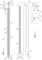
FIG. 4A is a cross-sectional view of the pump ofFIG. 2 , taken along line 4-4 inFIG. 2 , where the pump is in a first configuration; -
FIG. 4B is a cross-sectional view of the pump ofFIG. 2 , taken along line 4-4 inFIG. 2 , where the pump is in a second configuration; -
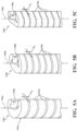
FIGS. 5A-5C show example coils for the pump according to the present disclosure; -
FIGS. 6A-6C are top perspective views of the example coils ofFIGS. 5A-5C ; -
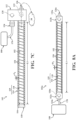
FIG. 7A is an example of the pump ofFIG. 2 , where the pump is in a first position; -
FIG. 7B is an example of the pump ofFIG. 2 , where the pump is in a second position; -
FIG. 7C is an example of the pump ofFIG. 2 , where the pump is in the first position; -
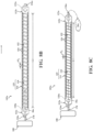
FIG. 8A is an example of a pump according to the present disclosure, where the pump is in a first position; -
FIG. 8B is an example of the pump ofFIG. 8A , where the pump is in a second position; -
FIG. 8C is an example of the pump ofFIG. 8A , where the pump is in the first position; -
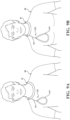
FIGS. 9A is a perspective view of an article of clothing incorporating a pump according to an example of the present disclosure, where the article of clothing is in a relaxed state; and -
FIG. 9B is a perspective view of the article of clothing ofFIG. 9A , where the article of clothing is in a constricted state. - Corresponding reference numerals indicate corresponding parts throughout the drawings.
- Example configurations will now be described more fully with reference to the accompanying drawings. Example configurations are provided so that this disclosure will be thorough, and will fully convey the scope of the disclosure to those of ordinary skill in the art. Specific details are set forth such as examples of specific components, devices, and methods, to provide a thorough understanding of configurations of the present disclosure. It will be apparent to those of ordinary skill in the art that specific details need not be employed, that example configurations may be embodied in many different forms, and that the specific details and the example configurations should not be construed to limit the scope of the disclosure.
- The terminology used herein is for the purpose of describing particular exemplary configurations only and is not intended to be limiting. As used herein, the singular articles "a," "an," and "the" may be intended to include the plural forms as well, unless the context clearly indicates otherwise. The terms "comprises," "comprising," "including," and "having," are inclusive and therefore specify the presence of features, steps, operations, elements, and/or components, but do not preclude the presence or addition of one or more other features, steps, operations, elements, components, and/or groups thereof. The method steps, processes, and operations described herein are not to be construed as necessarily requiring their performance in the particular order discussed or illustrated, unless specifically identified as an order of performance. Additional or alternative steps may be employed.
- When an element or layer is referred to as being "on," "engaged to," "connected to," "attached to," or "coupled to" another element or layer, it may be directly on, engaged, connected, attached, or coupled to the other element or layer, or intervening elements or layers may be present. In contrast, when an element is referred to as being "directly on," "directly engaged to," "directly connected to," "directly attached to," or "directly coupled to" another element or layer, there may be no intervening elements or layers present. Other words used to describe the relationship between elements should be interpreted in a like fashion (e.g., "between" versus "directly between," "adjacent" versus "directly adjacent," etc.). As used herein, the term "and/or" includes any and all combinations of one or more of the associated listed items.
- The terms first, second, third, etc. may be used herein to describe various elements, components, regions, layers and/or sections. These elements, components, regions, layers and/or sections should not be limited by these terms. These terms may be only used to distinguish one element, component, region, layer or section from another region, layer or section. Terms such as "first," "second," and other numerical terms do not imply a sequence or order unless clearly indicated by the context. Thus, a first element, component, region, layer or section discussed below could be termed a second element, component, region, layer or section without departing from the teachings of the example configurations.
- In one configuration, a pump is provided an includes a conduit defining an inner volume and formed from a flexible material, the conduit movable between an expanded state and a relaxed state. A coil is disposed within the conduit and includes an outer diameter that is approximately equal to an inner diameter of the conduit, the coil substantially maintaining its outer diameter when the conduit is moved between the relaxed state and the expanded state. A manifold is in fluid communication with the inner volume and is operable to permit fluid to enter the inner volume in a first mode and expel fluid from the inner volume in a second mode.
- The pump may include one or more of the following optional features. For example, the coil may be formed from a different material than a material forming the conduit. Namely, the coil could be formed from a foam material. Additionally or alternatively, the coil may include a helical shape.
- In one configuration, the coil may define a passageway formed therethrough. The passageway may include a longitudinal axis that is substantially parallel to a longitudinal axis of the coil. Additionally or alternatively, the manifold may include a first valve permitting fluid flow into the inner volume and preventing fluid flow out of the inner volume in the first mode and a second valve permitting fluid flow out of the inner volume and preventing fluid flow into the inner volume in the second mode. At least one of the first valve and the second valve may be a check valve.
- An article of footwear may incorporate the pump.
- An article of apparel may incorporate the pump.
- In another configuration, a pump is provided and includes a conduit defining an inner volume and movable between an expanded state and a relaxed state, an effective length of the conduit being increased when moved from the relaxed state to the expanded state. A coil is disposed within the conduit, includes an outer diameter that is approximately equal to an inner diameter of the conduit, and has an effective length that is increased when the conduit is moved from the relaxed state to the expanded state, the coil substantially maintaining its outer diameter when the conduit is moved between the relaxed state and the expanded state. A manifold is in fluid communication with the inner volume and is operable to permit fluid to enter the inner volume in a first mode and expel fluid from the inner volume in a second mode.
- The pump may include one or more of the following optional features. For example, the coil may formed from a different material than a material forming the conduit. Namely, the coil could be formed from a foam material. Additionally or alternatively, the coil may include a helical shape.
- In one configuration, the coil may define a passageway formed therethrough. The passageway may include a longitudinal axis that is substantially parallel to a longitudinal axis of the coil. Additionally or alternatively, the manifold may include a first valve permitting fluid flow into the inner volume and preventing fluid flow out of the inner volume in the first mode and a second valve permitting fluid flow out of the inner volume and preventing fluid flow into the inner volume in the second mode. At least one of the first valve and the second valve may be a check valve.
- An article of footwear may incorporate the pump.
- An article of apparel may incorporate the pump.
- The details of one or more implementations of the disclosure are set forth in the accompanying drawings and the description below. Other aspects, features, and advantages will be apparent from the description, the drawings, and the claims.
- Referring to
FIGS. 1A and1B , an article offootwear 10 includes an upper 100 and asole structure 200 attached to the upper 100. The article offootwear 10 may further include ananterior end 12 associated with a forward-most point of thefootwear 10, and aposterior end 14 corresponding to a rearward-most point of thefootwear 10. A longitudinal axis A10 of thefootwear 10 extends along a length of thefootwear 10 from theanterior end 12 to theposterior end 14 parallel to a ground surface, and generally divides thefootwear 10 into amedial side 16 and alateral side 18. Accordingly, themedial side 16 and thelateral side 18 respectively correspond with opposite sides of thefootwear 10 and extend from theanterior end 12 to theposterior end 14. As used herein, a longitudinal direction refers to the direction extending from theanterior end 12 to theposterior end 14, while a lateral direction refers to the direction transverse to the longitudinal direction and extending from themedial side 16 to thelateral side 18. - The article of
footwear 10 may be divided into one or more regions. The regions may include a forefoot region 20, amid-foot region 22, and aheel region 24. The forefoot region 20 may correspond with the phalanges and the metatarsal bones of a foot. Themid-foot region 22 may correspond with an arch area of the foot, and theheel region 24 may correspond with rear portions of the foot, including a calcaneus bone. - As shown, the
sole structure 200 includes amidsole 202 configured to provide cushioning and support and an outsole 204 defining a ground-engaging surface of thesole structure 200. In other examples, themidsole 202 may be configured as a composite structure including a plurality of components joined together. Stitching or adhesives may secure themidsole 202 to the upper 100, while a bottom surface of the outsole 204 defines a ground-engaging surface of thesole structure 200. - The article of
footwear 10 may further include apump 102 and a release valve 104. Thepump 102 extends across the upper 100 and may be in fluid communication with the upper 100 through one or more valves to adjust a pressure in the upper 100 from a first pressure (e.g., at or above ambient) to a second pressure (e.g., below ambient) by removing fluid (e.g., a gas or liquid) from the upper 100. The release valve 104 may be fluidly coupled to the upper 100 and serves to selectively permit fluid to enter the upper 100 to return the upper 100 to the first pressure. As discussed in greater detail below, thepump 102 and the release valve 104 cooperate to transition the upper 100 between a relaxed state (FIG. 1A ) and a constricted state (FIG. 1B ). - Referring to
FIGS. 2-4B and7A-7C , thepump 102 includes a first end 106 coupled to the article offootwear 10 and a second end 108 coupled to the article offootwear 10 and disposed on an opposite end of thepump 102 than the first end 106. Thepump 102 further includes anendcap 110 disposed at the first end 106, a manifold 112 disposed at the second end 108, and anouter tube 114 extending between and connecting theendcap 110 and the manifold 112 to enclose achamber 116 defined by thepump 102. Thepump 102 further includes apump core 118 sized to be received by thechamber 116. Thepump core 118 substantially fills theouter tube 114 and extends between theendcap 110 and themanifold 112. When assembled, theouter tube 114 and thecoil 118 further define anactuator cable 119. - The
endcap 110 and the manifold 112 may include any suitable lightweight material, such as nylon (PA), polypropylene (PP), carbon, or an aluminum alloy. Theouter tube 114 may include rubber, latex, butyl, silicone, or any other tubing that is highly elastic and retains its properties under a high number of cycles. Thepump core 118 may include a flexible material such as a PP, PA, thermoplastic polyurethane (TPU), rubber, closed cell foam, BRSX, or any other material that retains its properties under a high number of cycles. When thepump 102 is assembled, thechamber 116 desirably has a low gas transmission rate to preserve its retained gas pressure. Theendcap 110, manifold 112, andouter tube 114 may be secured together by compression fit, adhesive, or by any other external securing means. - The manifold 112 includes an
inlet check valve 120 configured to selectively allow fluid to flow into thechamber 116, and anexhaust check valve 122 configured to selectively permit fluid to flow out of thechamber 116. Theinlet check valve 118 may further include anintake port 124 connecting theinlet check valve 120 of thepump 102 to the upper 100, and anexhaust port 126 connecting theexhaust check valve 122 of thepump 100 to the outside air (e.g., ambient). - With continued reference to
FIG. 3 , theendcap 110 is defined by anouter end 128 corresponding to the first end 106 of thepump 102, and aninner end 130 formed on an opposite side of theendcap 110 than theouter end 128 and facing theouter tube 114. The manifold 112 is further defined by anouter end 132 corresponding to the second end 108 of thepump 102, and aninner end 134 formed on an opposite side of the manifold 112 than theouter end 132 and facing theouter tube 114. Theouter tube 114 is defined by afirst end 136 facing theinner end 130 of theendcap 110, asecond end 138 formed on an opposite side of theouter tube 114 than thefirst end 136 and facing theinner end 134 of the manifold 112, and aninner surface 140. - In the illustrated example, the
pump core 118 includes acoil 118 extending from afirst end 142 coupled to theinner end 130 of theendcap 110, to asecond end 144 coupled to theinner end 134 of themanifold 112. Thecoil 118 may further include anouter surface 146 defining the outer diameter of thecoil 118. In some implementations, one or both of thefirst end 142 and thesecond end 144 are fully detached from theinner end 130 of theendcap 110 and theinner end 134 of themanifold 112. - The
coil 118 is disposed within thechamber 116 of thepump 102 and, with theouter tube 114, forms a transformable structure (i.e., the actuator cable 119) operable to transition thepump 102 between a relaxed state and a stretched state. When thepump 102 is assembled, theouter surface 146 of thecoil 118 faces theinner surface 140 of theouter tube 114, and may be attached to theinner surface 140. Thus, as theouter tube 114 moves between the relaxed state and the stretched state, theinner surface 140 of theouter tube 114 directly pulls thecoil 118 to transition thecoil 118 from the relaxed state to the stretched state. - In other examples, the
outer surface 146 of thecoil 118 may be fully detached from theinner surface 140 of theouter tube 114. In this configuration, the coil is free to slide with respect to theinner surface 140 of the outer tube as theouter tube 140 of thepump 102 transitions between the relaxed state and the stretched state. Here, theouter surface 146 of thecoil 118 may be indirectly influenced into the relaxed and stretched states by theouter tube 114. Alternatively, theouter surface 146 of thecoil 118 may be zonally attached to theinner surface 140 of theouter tube 114 and/or may be attached at theends - Referring to
FIGS 4A and 4B , theactuator cable 119 including theouter tube 114 and thecoil 118 is shown. Thecoil 118 is further defined by a continuouselongated member 152 arranged in a helical manner to define a plurality ofthreads 154, a coil pitch P between opposingthreads 154, and a through-hole 156 extending axially from thefirst end 142 to thesecond end 144 of thecoil 118. Generally, as thepump 102 transitions from the relaxed state to the stretched state, thecoil 118 is configured to maintain its diametric dimension while extending axially. In other words, the continuouselongated member 152 maintains a generally consistent cross-section (i.e., thickness) while the coil pitch P between each opposingthreads 154 changes while in the relaxed state and the stretched state. Consequently, thecoil 118 prevents theouter tube 114 from collapsing when thepump 102 moves between the relaxed state and the stretched state. In some implementations, thecoil 118 may not include a through-hole 156, to further fill theouter tube 114 in the relaxed state. Examples of different geometries of thecoil 118 are discussed below with respect toFIGS. 5A-6C . - The
outer tube 114 and thecoil 118 are configured to stretch when a force is applied to the actuator cable 119 (i.e., theactuator cable 119 is pulled in a tightening direction 148). Due to the resiliency of theouter tube 114 and thecoil 118, theactuator cable 119 returns to a resting length when released. Accordingly, theactuator cable 119 is operable to actuate theouter tube 114 and thecoil 118 between a first position associated with a first length L1 where theouter tube 114 and thecoil 118 are in a resting state (FIG. 4A ), and a second position associated with a second length L2 where theouter tube 114 and thecoil 118 are in a stretched state (FIG. 4B ). Additionally, the first position is associated with a first pitch P1 (FIG. 4A ) of thecoil 118, and the second position is associated with a second pitch P2 (FIG. 4B ) of thecoil 118, where the second pitch P2 is a greater distance between thethreads 154 of theelongated member 152 than the first pitch P1. When theactuator cable 119 is in the first position, the first pitch P1 may allow thecoil 118 to substantially fill theouter tube 114. As theactuator cable 119 is actuated into the second position, thecoil 118 stretches axially, increasing the pitch from the first pitch P1 to the second pitch P2, which allows air to be drawn into thechamber 116 of thepump 102 by substantially maintaining an inner diameter of theouter tube 114. Consequently, and as discussed below, cycling theactuator cable 119 between the first position and the second position operates to draw fluid in through theintake port 124 and exhaust fluid out through theexhaust port 126 when the force is released. This is accomplished by thecoil 118 causing theouter tube 114 to maintain its diameter as the length of theouter tube 114 is increased due to the force exerted thereon. The increased length of thetube 114 along with it maintaining its relaxed diameter during elongation causes an internal volume of thetube 114 to increase, thereby causing fluid to be drawn into thetube 114 via theintake port 124. - Referring now to
FIGS. 5A-6C , various geometries ofcoils 118a-118c are illustrated. As discussed above, theouter tube 114 is sized to receive thecoil 118. Accordingly, the geometry ofcoil 118a-118c will dictate the geometry of its correspondingouter tube 114. Thecoils 118a-118c are defined by a continuouselongated member 152 arranged in a helical manner. This arrangement forms the plurality ofthreads 154a-154c defining the coil pitches Pa-Pc between opposingthreads 154a-154c, and the through-holes 156a-156c extending axially from thefirst end 142 to thesecond end 144 of thecoils 118a-118c. Each of thecoils 118a-118c may further be defined by a correspondingcross-sectional area 158a-158c. - For example,
FIGS. 5A and6A show acoil 118a that includes a helical continuouselongated member 152a in a circle-shape (i.e., circular helix). In these examples, thecross-sectional area 158a is shaped in a square shape, and wraps around the through-hole 156a to formthreads 154a separated by coil pitches Pa. As shown, the through-hole 156a is also circle-shaped to correspond to the circle shape of thecoil 118a. Alternatively, acoil 118b includes a helical continuouselongated member 152b in an oval shape (FIGS. 5B and6B ). In these implementations, thecross-sectional area 158b is shaped in a rectangular shape, and wraps around the through-hole 158b to formthreads 154b separated by coil pitches Pb. As shown, the through-hole 156b is generally shaped as an elongated slot having a pair of rounded ends and substantially straight intermediate portions. In some examples, (FIGS. 5C and6C ), acoil 118c includes a helical continuouselongated member 152c in an elongated slot shape having a pair of rounded ends and substantially straight intermediate portions. In these examples, thecross-sectional area 158c is shaped in a rectangular shape, and wraps around the through-hole 158c to form threads 154c separated by coil pitches Pc. As shown, the through-hole 156c is generally shaped as an elongated slot having a pair of rounded ends and substantially straight intermediate portions. - Referring briefly to
FIGS. 1A and1B , the upper 100 may be formed from one or more materials that are stitched or adhesively bonded together to define aninterior void 160. Suitable materials of the upper 100 may include, but are not limited to, textiles, foam, leather, and synthetic leather. The example upper 100 may be formed from a combination of one or more substantially inelastic or non-stretchable materials and one or more substantially elastic or stretchable materials disposed in different regions of the upper 100 to facilitate movement of the article offootwear 10 between the constricted state and the relaxed state. The one or more elastic materials may include any combination of one or more elastic fabrics such as, without limitation, spandex, elastane, rubber or neoprene. The one or more inelastic materials may include any combination of one or more of thermoplastic polyurethanes, nylon, leather, vinyl, or another material/fabric that does not impart properties of elasticity. - In the illustrated example, the upper 100 includes one or more
fluid chambers 162 in fluid communication with thepump 102. Each of thechambers 162 includes acompressible component 164 disposed therein that compresses as the upper 100 transitions from the relaxed state (FIG. 1A ) to the constricted state (FIG. 1B ). Thecompressible component 164 may include alattice structure 166 defining a plurality of reliefs 168 (e.g., openings). As discussed above with reference toFIGS. 1A and1B , thepump 102 is in fluid communication with thechambers 162 of the upper 100. In these implementations, anintake conduit 170 connects theintake port 124 including theinlet check valve 120 to thechambers 162 of the upper 100 allowing fluid communication between thepump 102 and the upper 100. In some implementations, the release valve 104 includes a release valve 105 including a Schrader valve that is selectively activated by the release valve 104 to allow outside air (e.g., ambient) to enter the upper 100 to return the upper 100 to a relaxed state from a constricted state. - In use, the pressure within the
chambers 162 of the upper 100 is reduced by drawing a vacuum within thechambers 162 of the upper 100 via thepump 102. As the pressure is reduced, the upper 100 moves from a relaxed state to a constricted state that forms the upper 100 around the wearer's foot. Thus, as the vacuum is drawn by cycling thepump 102, as described below with respect toFIGS. 7A-8C , fluid is drawn from within thechambers 162 of the upper 100 and into thechamber 116 of thepump 102 to compress thelattice structure 166 of thecompressible component 164, thereby constricting the upper 100 around the foot of the wearer. When the release valve 104 is actuated, thelattice structure 166 of thecompressible component 164 expands within eachchamber 162, thereby causing an internal volume of thechamber 162 to increase. The increase in volume draws fluid from the release valve 105 of the release valve 104 and allows the upper 100 to move to the relaxed state around the wearer of the foot. Optionally, the upper 100 may include a locking system which, when activated, locks the geometry of the upper 100 in place once it is in the constricted state. - With continued reference to
FIGS. 7A-7B , the upper 100 may be transitioned between the relaxed state and the constricted state via thepump 102. Here, a vacuum may be drawn by pulling theactuator cable 119 in the tightening direction 148 (i.e., moving thecable 119 away from the upper 100) and releasing theactuator cable 119 for a number of cycles. As theactuator cable 119 is pulled in the tightening direction, theouter tube 114 and thecoil 118 are moved from the first position (FIG. 7A ) associated with the first length L1 to the second position (FIG. 7B ) associated with the second length L2. Concurrently, the coil pitch P extends from the first coil pitch P1 associated with the first length L1 to the second coil pitch P2 associated with the second length L2, thereby creating space between thethreads 154 of thecoil 118 and creating avacuum drawing fluid 30 from the upper 100 into thechamber 116 via theintake port 124 and theinlet check valve 120. Once theactuator cable 119 is in the second position, theinlet check valve 120 closes to prevent the fluid 30 from escaping thechamber 116 back into thechambers 162 of the upper 100. - When the
actuator cable 119 is released, the resiliency of theouter tube 114 and thecoil 118 bias theactuator cable 119 from the second position (FIG. 7B ) associated with the second length L2 to the first position (FIG. 7C ) associated with the first length L1, decreasing the coil pitch P from the second coil pitch P2 to the first coil pitch P2 and exhausting the fluid 30 within thechamber 116 through theexhaust check valve 126 and theexhaust check valve 122. Thus, the fluid 30 drawn from thechambers 162 when theactuator cable 119 moves from the first position to the second position is exhausted from thepump 102 when theouter tube 114 and thecoil 118 return from the second position to the first position. Accordingly, the steps of pulling theactuator cable 119 in the tighteningdirection 148 followed by releasing theactuator cable 119 constitutes a cycle. For each cycle that theactuator cable 119 is pulled in the tighteningdirection 118 and released, the pressure within the upper 100 is incrementally reduced. In some examples, the pressure within the upper 100 reaches an ideal pressure to constrict the upper 100 (e.g., -5 psi) after three pulls on theactuator cable 119. In other examples, fewer or more pulls on theactuator cable 119 are required. - While not shown, when the wearer wishes to move the upper 100 to the relaxed state, the wearer increases the pressure within the
chambers 162 of the upper 100 by pressing the release valve 104 of the release valve 105. Specifically, the wearer may press the release valve 104 located on the outer surface of thesole structure 200, which biases the release valve 105 to an open position to allow ambient air to flow within thechambers 162 of the upper 100. Consequently, the pressure within thechambers 162 of the upper 100 increases, and the upper 100 transitions from the constricted state (FIG. 1B ) to the relaxed state (FIG. 1A ) around the wearer's foot. - With particular reference to
FIGS. 8A-8C , another example of a configuration of apump 102a is shown. In view of the substantial similarity in structure and function of the components associated with thepump 102 with respect to thepump 102a, like reference numerals are used hereinafter and in the drawings to identify like components while like reference numerals containing letter extensions are used to identify those components that have been modified. - The
pump 102a includes theactuator cable 119 including theouter tube 114 and thecoil 118 with respect toFIGS. 7A-7C , but includes an alternate arrangement of check valves. Here, thepump 102a includes afirst manifold 112a disposed on the first end 106 and including aninlet check valve 120a and asecond manifold 112b disposed on the second end 108 and including anoutlet check valve 122a. Accordingly, theinlet check valve 120a and theoutlet check valve 122a are inline, as shown inFIGS. 8A-8C . A vacuum may be drawn by pulling theactuator cable 119 in the tighteningdirection 148 and releasing theactuator cable 119 for a number of cycles. As theactuator cable 119 is pulled in the tightening direction, theouter tube 114 and thecoil 118 are moved from the first position (FIG. 8A ) associated with the first length L1 to the second position (FIG. 8B ) associated with the second length L2. Concurrently, the coil pitch P extends from the first coil pitch P1 associated with the first length L1 to the second coil pitch P2 associated with the second length L2, thereby creating space between thethreads 154 of thecoil 118 and creating a vacuum drawing fluid 30a from the upper 100 into thechamber 116 via anintake port 124a and theinlet check valve 120a disposed on the first end 106 of thepump 102a. Once theactuator cable 119 is in the second position, theinlet check valve 120a closes to prevent the fluid 30a from escaping thechamber 116 back into thechambers 162 of the upper 100. - When the
actuator cable 119 is released, the resiliency of theouter tube 114 and thecoil 118 bias theactuator cable 119 from the second position (FIG. 7B ) associated with the second length L2 to the first position (FIG. 7C ) associated with the first length L1, decreasing the coil pitch P from the second coil pitch P2 to the first coil pitch P1 and exhausting the fluid 30 within thechamber 116 through anexhaust check valve 126a and the exhaust check valve 122b disposed on the second end 108 of thepump 102a. Thus, thefluid 30a drawn from thechambers 162 when theactuator cable 119 moves from the first position to the second position is exhausted from thepump 102a when theouter tube 114 and thecoil 118 return from the second position to the first position. - While not shown, the
inlet check valves exhaust check valves pump 102 that creates positive pressure (i.e., creates pressure in the upper 100) rather than negative pressure (i.e., pulls a vacuum in the upper 100). - Referring to
FIGS. 9A and 9B , thepump 102 may be incorporated into an article of apparel such asshirt 40. In this example, theshirt 40 may include one or more fluid-filledchambers 42 in fluid communication with thepump 102. As discussed with reference toFIGS. 1A and1B , thechambers 42 may include a compressible component disposed therein which compresses as theshirt 40 transitions from a relaxed state (FIG. 9A ) to a constricted state (FIG. 9B ). In these implementations, anintake conduit 44 connects thepump 102 to thechambers 42 of theshirt 40 allowing fluid communication between thepump 102 and theshirt 40. - In use, the
shirt 40 begins in the relaxed state (FIG. 9A ), and the wearer actuates thepump 102 by moving theactuator cable 119 from the first position to the second position thereby creating a vacuum drawing fluid from theshirt 40 into thechamber 116 of thepump 102. Once theactuator cable 119 is in the second position, theinlet check valve 120 closes to prevent the fluid from escaping thechamber 116 back into thechambers 42 of theshirt 40. - When the
actuator cable 119 is released, the resiliency of theouter tube 114 and thecoil 118 biases theactuator cable 119 from the second position to the first position and exhausting the fluid 30 within thechamber 116 through theexhaust check valve 126 and theexhaust check valve 122. Thus, the fluid 30 drawn from thechambers 42 when theactuator cable 119 moves from the first position to the second position is exhausted from thepump 102 when theouter tube 114 and thecoil 118 return from the second position to the first position. Accordingly, theshirt 40 moves from a relaxed state to a constricted state around the wearer's body. - The following Clauses provide an exemplary configuration for a pump for an article of footwear or apparel described above.
- Clause 1. A pump comprising a conduit defining an inner volume and formed from a flexible material, the conduit movable between an expanded state and a relaxed state, a coil disposed within the conduit and including an outer diameter that is approximately equal to an inner diameter of the conduit, the coil substantially maintaining its outer diameter when the conduit is moved between the relaxed state and the expanded state, and a manifold in fluid communication with the inner volume and operable to permit fluid to enter the inner volume in a first mode and expel fluid from the inner volume in a second mode.
-
Clause 2. The pump of Clause 1, wherein the coil is formed from a different material than a material forming the conduit. -
Clause 3. The pump of Clause 1, wherein the coil is formed from a foam material. - Clause 4. The pump of Clause 1, wherein the coil has a helical shape.
- Clause 5. The pump of Clause 4, wherein the coil defines a passageway formed therethrough.
- Clause 6. The pump of Clause 5, wherein the passageway includes a longitudinal axis that is substantially parallel to a longitudinal axis of the coil.
- Clause 7. The pump of Clause 1, wherein the manifold includes a first valve permitting fluid flow into the inner volume and preventing fluid flow out of the inner volume in the first mode and a second valve permitting fluid flow out of the inner volume and preventing fluid flow into the inner volume in the second mode.
- Clause 8. The pump of Clause 7, wherein at least one of the first valve and the second valve is a check valve.
- Clause 9. An article of footwear incorporating the pump of Clause 1.
-
Clause 10. An article of apparel incorporating the pump of Clause 1. - Clause 11. A pump comprising a conduit defining an inner volume and movable between an expanded state and a relaxed state, an effective length of the conduit being increased when moved from the relaxed state to the expanded state, a coil disposed within the conduit, including an outer diameter that is approximately equal to an inner diameter of the conduit, and having an effective length that is increased when the conduit is moved from the relaxed state to the expanded state, the coil substantially maintaining its outer diameter when the conduit is moved between the relaxed state and the expanded state, and a manifold in fluid communication with the inner volume and operable to permit fluid to enter the inner volume in a first mode and expel fluid from the inner volume in a second mode.
-
Clause 12. The pump of Clause 11, wherein the coil is formed from a different material than a material forming the conduit. - Clause 13. The pump of Clause 11, wherein the coil is formed from a foam material.
-
Clause 14. The pump of Clause 11, wherein the coil has a helical shape. - Clause 15. The pump of
Clause 14, wherein the coil defines a passageway formed therethrough. -
Clause 16. The pump of Clause 15, wherein the passageway includes a longitudinal axis that is substantially parallel to a longitudinal axis of the coil. -
Clause 17. The pump of Clause 11, wherein the manifold includes a first valve permitting fluid flow into the inner volume and preventing fluid flow out of the inner volume in the first mode and a second valve permitting fluid flow out of the inner volume and preventing fluid flow into the inner volume in the second mode. -
Clause 18. The pump ofClause 17, wherein at least one of the first valve and the second valve is a check valve. - Clause 19. An article of footwear incorporating the pump of Clause 11.
- Clause 20. An article of apparel incorporating the pump of Clause 11.
- The foregoing description has been provided for purposes of illustration and description. It is not intended to be exhaustive or to limit the disclosure. Individual elements or features of a particular configuration are generally not limited to that particular configuration, but, where applicable, are interchangeable and can be used in a selected configuration, even if not specifically shown or described. The same may also be varied in many ways. Such variations are not to be regarded as a departure from the disclosure, and all such modifications are intended to be included within the scope of the disclosure.
Claims (15)
- An article of footwear comprising:a pump comprising:a conduit defining an inner volume and formed from a flexible material, the conduit movable between an expanded state and a relaxed state;a coil disposed within the conduit and including an outer diameter that is approximately equal to an inner diameter of the conduit, the coil substantially maintaining its outer diameter when the conduit is moved between the relaxed state and the expanded state; anda manifold in fluid communication with the inner volume and operable to permit fluid to enter the inner volume in a first mode and expel fluid from the inner volume in a second mode;wherein the pump includes a first end coupled to the article of footwear and a second end coupled to the article of footwear and disposed on an opposite end of the pump than the first end .
- The article of footwear of Claim 1, wherein the coil is formed from a different material than a material forming the conduit.
- The article of footwear of Claim 1, wherein the coil is formed from a foam material.
- The article of footwear of Claim 1, wherein the coil has a helical shape.
- The article of footwear of Claim 4, wherein the coil defines a passageway formed therethrough, and
wherein optionally the passageway includes a longitudinal axis that is substantially parallel to a longitudinal axis of the coil. - The article of footwear of Claim 1, wherein the manifold includes a first valve permitting fluid flow into the inner volume and preventing fluid flow out of the inner volume in the first mode and a second valve permitting fluid flow out of the inner volume and preventing fluid flow into the inner volume in the second mode, and
wherein optionally at least one of the first valve and the second valve is a check valve. - The article of footwear of Claim 1, further comprising an upper, the pump extending across the upper.
- The article of footwear of Claim 1, further comprising a sole structure defining a ground - engaging surface.
- An article of footwear comprising:an upper; anda pump comprising:a conduit defining an inner volume and formed from a flexible material, the conduit movable between an expanded state and a relaxed state and extending across the upper;a coil disposed within the conduit and including an outer diameter that is approximately equal to an inner diameter of the conduit, the coil substantially maintaining its outer diameter when the conduit is moved between the relaxed state and the expanded state; anda manifold in fluid communication with the inner volume and operable to permit fluid to enter the inner volume in a first mode and expel fluid from the inner volume in a second mode.
- The article of footwear of Claim 9, wherein the coil is formed from a different material than a material forming the conduit.
- The article of footwear of Claim 9, wherein the coil is formed from a foam material.
- The article of footwear of Claim 9, wherein the coil has a helical shape, andwherein optionally the coil defines a passageway formed therethrough, andwherein further optionally the passageway includes a longitudinal axis that is substantially parallel to a longitudinal axis of the coil.
- The article of footwear of Claim 9, wherein the manifold includes a first valve permitting fluid flow into the inner volume and preventing fluid flow out of the inner volume in the first mode and a second valve permitting fluid flow out of the inner volume and preventing fluid flow into the inner volume in the second mode, and
wherein optionally at least one of the first valve and the second valve is a check valve. - The article of footwear of Claim 9, wherein the coil substantially fills the conduit.
- The article of footwear of Claim 9, further comprising a sole structure defining a ground - engaging surface, at least one of a first end of the pump and a second end of the pump being disposed proximate to the sole structure.
Applications Claiming Priority (3)
| Application Number | Priority Date | Filing Date | Title |
|---|---|---|---|
| US202163228402P | 2021-08-02 | 2021-08-02 | |
| PCT/US2022/074323 WO2023015136A1 (en) | 2021-08-02 | 2022-07-29 | Pump for article of footwear or apparel |
| EP22758102.2A EP4380406B1 (en) | 2021-08-02 | 2022-07-29 | Pump for article of footwear or apparel |
Related Parent Applications (1)
| Application Number | Title | Priority Date | Filing Date |
|---|---|---|---|
| EP22758102.2A Division EP4380406B1 (en) | 2021-08-02 | 2022-07-29 | Pump for article of footwear or apparel |
Publications (2)
| Publication Number | Publication Date |
|---|---|
| EP4579078A2 true EP4579078A2 (en) | 2025-07-02 |
| EP4579078A3 EP4579078A3 (en) | 2025-08-13 |
Family
ID=83006210
Family Applications (2)
| Application Number | Title | Priority Date | Filing Date |
|---|---|---|---|
| EP25175978.3A Pending EP4579078A3 (en) | 2021-08-02 | 2022-07-29 | Pump for article of footwear or apparel |
| EP22758102.2A Active EP4380406B1 (en) | 2021-08-02 | 2022-07-29 | Pump for article of footwear or apparel |
Family Applications After (1)
| Application Number | Title | Priority Date | Filing Date |
|---|---|---|---|
| EP22758102.2A Active EP4380406B1 (en) | 2021-08-02 | 2022-07-29 | Pump for article of footwear or apparel |
Country Status (4)
| Country | Link |
|---|---|
| US (2) | US12188466B2 (en) |
| EP (2) | EP4579078A3 (en) |
| CN (1) | CN117729862A (en) |
| WO (1) | WO2023015136A1 (en) |
Families Citing this family (4)
| Publication number | Priority date | Publication date | Assignee | Title |
|---|---|---|---|---|
| US12433370B2 (en) | 2021-04-14 | 2025-10-07 | Nike, Inc. | Vacuum transform upper for article of footwear |
| US12369690B2 (en) * | 2022-04-28 | 2025-07-29 | Nike, Inc. | Integrated manual pump for article of footwear |
| US12326143B2 (en) * | 2022-11-18 | 2025-06-10 | University Of Southern California | Longitudinal impedance pump |
| WO2024206859A1 (en) * | 2023-03-30 | 2024-10-03 | Nike Innovate C.V. | Sole structure for article of footwear |
Family Cites Families (18)
| Publication number | Priority date | Publication date | Assignee | Title |
|---|---|---|---|---|
| BE555331A (en) * | 1956-03-02 | 1900-01-01 | ||
| US3422681A (en) * | 1966-06-14 | 1969-01-21 | Atomic Energy Commission | Vehicle actuated roadside air sampling device |
| DE2146248C3 (en) * | 1971-09-16 | 1980-06-26 | Draegerwerk Ag, 2400 Luebeck | Gas detector or dust detector and measuring device |
| DE2212363A1 (en) * | 1972-03-15 | 1973-09-20 | Draegerwerk Ag | GAS PURE DEVICE |
| US4338826A (en) * | 1980-09-11 | 1982-07-13 | Air Test Labs, Inc. | Sampling apparatus |
| US5987779A (en) * | 1987-08-27 | 1999-11-23 | Reebok International Ltd. | Athletic shoe having inflatable bladder |
| US4858478A (en) * | 1988-08-16 | 1989-08-22 | Mine Safety Appliances Company | Bellows type hand-operated air sampling pump |
| US5230249A (en) * | 1990-08-20 | 1993-07-27 | Casio Computer Co., Ltd. | Shoe or boot provided with tank chambers |
| US5222312A (en) | 1991-07-02 | 1993-06-29 | Doyle Harold S | Shoe with pneumatic inflating device |
| US6287095B1 (en) * | 1999-07-05 | 2001-09-11 | Intex Recreation Corp. | Internal air pump for inflatables |
| JP3571661B2 (en) * | 2001-02-16 | 2004-09-29 | 株式会社ツー・アンド・ワン | Golf shoes |
| US7784196B1 (en) * | 2006-12-13 | 2010-08-31 | Reebok International Ltd. | Article of footwear having an inflatable ground engaging surface |
| KR101404716B1 (en) * | 2013-05-22 | 2014-06-09 | (주)대우건설 | Surging removing device for constructing shotcrete |
| US9609904B2 (en) * | 2015-04-23 | 2017-04-04 | Adidas Ag | Shoes for ball sports |
| US10595584B2 (en) * | 2016-01-28 | 2020-03-24 | Christopher Anthony Silva | Adjustable article system |
| US10405608B2 (en) * | 2016-10-26 | 2019-09-10 | Nike, Inc. | Lacing system with loops for tightening and loosening |
| TWI633848B (en) * | 2017-04-11 | 2018-09-01 | 研能科技股份有限公司 | Shoes inflating and charging device |
| US11653712B2 (en) * | 2020-02-10 | 2023-05-23 | Reebok International Limited | Automatic inflation pump bladder system |
-
2022
- 2022-07-29 CN CN202280052951.6A patent/CN117729862A/en active Pending
- 2022-07-29 WO PCT/US2022/074323 patent/WO2023015136A1/en not_active Ceased
- 2022-07-29 EP EP25175978.3A patent/EP4579078A3/en active Pending
- 2022-07-29 EP EP22758102.2A patent/EP4380406B1/en active Active
- 2022-07-29 US US17/816,267 patent/US12188466B2/en active Active
-
2024
- 2024-12-02 US US18/965,777 patent/US20250092869A1/en active Pending
Also Published As
| Publication number | Publication date |
|---|---|
| EP4380406A1 (en) | 2024-06-12 |
| WO2023015136A1 (en) | 2023-02-09 |
| EP4579078A3 (en) | 2025-08-13 |
| US20230033238A1 (en) | 2023-02-02 |
| EP4380406B1 (en) | 2025-05-14 |
| US12188466B2 (en) | 2025-01-07 |
| US20250092869A1 (en) | 2025-03-20 |
| CN117729862A (en) | 2024-03-19 |
Similar Documents
| Publication | Publication Date | Title |
|---|---|---|
| EP4579078A2 (en) | Pump for article of footwear or apparel | |
| US12075883B2 (en) | Adjustable mutli-bladder system for an article of footwear | |
| US20230073035A1 (en) | Sole structure for article of footwear | |
| KR102222081B1 (en) | Article of footwear having a flexible fluid-filled chamber | |
| US12376642B2 (en) | Vacuum locking for article of footwear or apparel | |
| EP1778037B1 (en) | Shoe having an inflatable bladder | |
| US7337560B2 (en) | Shoe having an inflatable bladder | |
| US20150305436A1 (en) | Pneumatically inflatable air bladder devices contained entirely within shoe sole or configured as shoe inserts | |
| US20240324725A1 (en) | Sole structure for article of footwear | |
| US20260123700A1 (en) | Pump for article of footwear or apparel | |
| US20240115001A1 (en) | Automatic pump for article of footwear | |
| US12369690B2 (en) | Integrated manual pump for article of footwear | |
| CN119053263A (en) | Integrated manual pump for an article of footwear | |
| US20250024915A1 (en) | Vacuum system for article of footwear or apparel | |
| WO2024081682A1 (en) | Automatic pump for article of footwear | |
| US20240358116A1 (en) | Fluid Systems and/or Laminated Structures Including Inflated Chambers for Controlling Fluid Flow in Fluid Lines and Products Including Such Fluid Systems and Structures | |
| EP4701478A1 (en) | Fluid systems and/or laminated structures including inflated chambers for controlling fluid flow in fluid lines and products including such fluid systems and structures | |
| WO2025019475A1 (en) | Vacuum system for article of footwear or apparel |
Legal Events
| Date | Code | Title | Description |
|---|---|---|---|
| PUAI | Public reference made under article 153(3) epc to a published international application that has entered the european phase |
Free format text: ORIGINAL CODE: 0009012 |
|
| STAA | Information on the status of an ep patent application or granted ep patent |
Free format text: STATUS: THE APPLICATION HAS BEEN PUBLISHED |
|
| AC | Divisional application: reference to earlier application |
Ref document number: 4380406 Country of ref document: EP Kind code of ref document: P |
|
| AK | Designated contracting states |
Kind code of ref document: A2 Designated state(s): AL AT BE BG CH CY CZ DE DK EE ES FI FR GB GR HR HU IE IS IT LI LT LU LV MC MK MT NL NO PL PT RO RS SE SI SK SM TR |
|
| PUAL | Search report despatched |
Free format text: ORIGINAL CODE: 0009013 |
|
| AK | Designated contracting states |
Kind code of ref document: A3 Designated state(s): AL AT BE BG CH CY CZ DE DK EE ES FI FR GB GR HR HU IE IS IT LI LT LU LV MC MK MT NL NO PL PT RO RS SE SI SK SM TR |
|
| RIC1 | Information provided on ipc code assigned before grant |
Ipc: F04B 33/00 20060101AFI20250710BHEP Ipc: F04B 41/02 20060101ALI20250710BHEP Ipc: F04B 45/06 20060101ALI20250710BHEP Ipc: F04B 43/08 20060101ALI20250710BHEP Ipc: A43B 23/02 20060101ALI20250710BHEP Ipc: A43C 7/06 20060101ALI20250710BHEP Ipc: A43C 11/16 20060101ALI20250710BHEP |
|
| STAA | Information on the status of an ep patent application or granted ep patent |
Free format text: STATUS: REQUEST FOR EXAMINATION WAS MADE |
|
| 17P | Request for examination filed |
Effective date: 20260212 |