EP4579074A1 - Evaporative emissions leak check module with volatile organic compound measurement - Google Patents
Evaporative emissions leak check module with volatile organic compound measurement Download PDFInfo
- Publication number
- EP4579074A1 EP4579074A1 EP24223102.5A EP24223102A EP4579074A1 EP 4579074 A1 EP4579074 A1 EP 4579074A1 EP 24223102 A EP24223102 A EP 24223102A EP 4579074 A1 EP4579074 A1 EP 4579074A1
- Authority
- EP
- European Patent Office
- Prior art keywords
- cvs
- canister
- ldm
- port
- controller
- Prior art date
- Legal status (The legal status is an assumption and is not a legal conclusion. Google has not performed a legal analysis and makes no representation as to the accuracy of the status listed.)
- Pending
Links
Images

Classifications
-
- F—MECHANICAL ENGINEERING; LIGHTING; HEATING; WEAPONS; BLASTING
- F02—COMBUSTION ENGINES; HOT-GAS OR COMBUSTION-PRODUCT ENGINE PLANTS
- F02M—SUPPLYING COMBUSTION ENGINES IN GENERAL WITH COMBUSTIBLE MIXTURES OR CONSTITUENTS THEREOF
- F02M25/00—Engine-pertinent apparatus for adding non-fuel substances or small quantities of secondary fuel to combustion-air, main fuel or fuel-air mixture
- F02M25/08—Engine-pertinent apparatus for adding non-fuel substances or small quantities of secondary fuel to combustion-air, main fuel or fuel-air mixture adding fuel vapours drawn from engine fuel reservoir
- F02M25/0809—Judging failure of purge control system
-
- B—PERFORMING OPERATIONS; TRANSPORTING
- B60—VEHICLES IN GENERAL
- B60K—ARRANGEMENT OR MOUNTING OF PROPULSION UNITS OR OF TRANSMISSIONS IN VEHICLES; ARRANGEMENT OR MOUNTING OF PLURAL DIVERSE PRIME-MOVERS IN VEHICLES; AUXILIARY DRIVES FOR VEHICLES; INSTRUMENTATION OR DASHBOARDS FOR VEHICLES; ARRANGEMENTS IN CONNECTION WITH COOLING, AIR INTAKE, GAS EXHAUST OR FUEL SUPPLY OF PROPULSION UNITS IN VEHICLES
- B60K5/00—Arrangement or mounting of internal-combustion or jet-propulsion units
-
- B—PERFORMING OPERATIONS; TRANSPORTING
- B60—VEHICLES IN GENERAL
- B60K—ARRANGEMENT OR MOUNTING OF PROPULSION UNITS OR OF TRANSMISSIONS IN VEHICLES; ARRANGEMENT OR MOUNTING OF PLURAL DIVERSE PRIME-MOVERS IN VEHICLES; AUXILIARY DRIVES FOR VEHICLES; INSTRUMENTATION OR DASHBOARDS FOR VEHICLES; ARRANGEMENTS IN CONNECTION WITH COOLING, AIR INTAKE, GAS EXHAUST OR FUEL SUPPLY OF PROPULSION UNITS IN VEHICLES
- B60K15/00—Arrangement in connection with fuel supply of combustion engines or other fuel consuming energy converters, e.g. fuel cells; Mounting or construction of fuel tanks
- B60K15/03—Fuel tanks
-
- F—MECHANICAL ENGINEERING; LIGHTING; HEATING; WEAPONS; BLASTING
- F02—COMBUSTION ENGINES; HOT-GAS OR COMBUSTION-PRODUCT ENGINE PLANTS
- F02D—CONTROLLING COMBUSTION ENGINES
- F02D41/00—Electrical control of supply of combustible mixture or its constituents
- F02D41/0025—Controlling engines characterised by use of non-liquid fuels, pluralities of fuels, or non-fuel substances added to the combustible mixtures
- F02D41/003—Adding fuel vapours, e.g. drawn from engine fuel reservoir
-
- F—MECHANICAL ENGINEERING; LIGHTING; HEATING; WEAPONS; BLASTING
- F02—COMBUSTION ENGINES; HOT-GAS OR COMBUSTION-PRODUCT ENGINE PLANTS
- F02M—SUPPLYING COMBUSTION ENGINES IN GENERAL WITH COMBUSTIBLE MIXTURES OR CONSTITUENTS THEREOF
- F02M25/00—Engine-pertinent apparatus for adding non-fuel substances or small quantities of secondary fuel to combustion-air, main fuel or fuel-air mixture
- F02M25/08—Engine-pertinent apparatus for adding non-fuel substances or small quantities of secondary fuel to combustion-air, main fuel or fuel-air mixture adding fuel vapours drawn from engine fuel reservoir
- F02M25/0809—Judging failure of purge control system
- F02M25/0818—Judging failure of purge control system having means for pressurising the evaporative emission space
-
- F—MECHANICAL ENGINEERING; LIGHTING; HEATING; WEAPONS; BLASTING
- F02—COMBUSTION ENGINES; HOT-GAS OR COMBUSTION-PRODUCT ENGINE PLANTS
- F02M—SUPPLYING COMBUSTION ENGINES IN GENERAL WITH COMBUSTIBLE MIXTURES OR CONSTITUENTS THEREOF
- F02M25/00—Engine-pertinent apparatus for adding non-fuel substances or small quantities of secondary fuel to combustion-air, main fuel or fuel-air mixture
- F02M25/08—Engine-pertinent apparatus for adding non-fuel substances or small quantities of secondary fuel to combustion-air, main fuel or fuel-air mixture adding fuel vapours drawn from engine fuel reservoir
- F02M25/0854—Details of the absorption canister
-
- F—MECHANICAL ENGINEERING; LIGHTING; HEATING; WEAPONS; BLASTING
- F02—COMBUSTION ENGINES; HOT-GAS OR COMBUSTION-PRODUCT ENGINE PLANTS
- F02M—SUPPLYING COMBUSTION ENGINES IN GENERAL WITH COMBUSTIBLE MIXTURES OR CONSTITUENTS THEREOF
- F02M25/00—Engine-pertinent apparatus for adding non-fuel substances or small quantities of secondary fuel to combustion-air, main fuel or fuel-air mixture
- F02M25/08—Engine-pertinent apparatus for adding non-fuel substances or small quantities of secondary fuel to combustion-air, main fuel or fuel-air mixture adding fuel vapours drawn from engine fuel reservoir
- F02M25/089—Layout of the fuel vapour installation
-
- B—PERFORMING OPERATIONS; TRANSPORTING
- B60—VEHICLES IN GENERAL
- B60K—ARRANGEMENT OR MOUNTING OF PROPULSION UNITS OR OF TRANSMISSIONS IN VEHICLES; ARRANGEMENT OR MOUNTING OF PLURAL DIVERSE PRIME-MOVERS IN VEHICLES; AUXILIARY DRIVES FOR VEHICLES; INSTRUMENTATION OR DASHBOARDS FOR VEHICLES; ARRANGEMENTS IN CONNECTION WITH COOLING, AIR INTAKE, GAS EXHAUST OR FUEL SUPPLY OF PROPULSION UNITS IN VEHICLES
- B60K15/00—Arrangement in connection with fuel supply of combustion engines or other fuel consuming energy converters, e.g. fuel cells; Mounting or construction of fuel tanks
- B60K15/03—Fuel tanks
- B60K2015/03328—Arrangements or special measures related to fuel tanks or fuel handling
-
- F—MECHANICAL ENGINEERING; LIGHTING; HEATING; WEAPONS; BLASTING
- F02—COMBUSTION ENGINES; HOT-GAS OR COMBUSTION-PRODUCT ENGINE PLANTS
- F02D—CONTROLLING COMBUSTION ENGINES
- F02D41/00—Electrical control of supply of combustible mixture or its constituents
- F02D41/22—Safety or indicating devices for abnormal conditions
- F02D2041/224—Diagnosis of the fuel system
- F02D2041/225—Leakage detection
Definitions
- This disclosure relates to a leak detection module (LDM) for an evaporative emissions system.
- LDM leak detection module
- the disclosure relates to an LDM that is able to measure volatile organic compounds (VOC) and transmit results to remote locations.
- VOC volatile organic compounds
- LDM leak detection module
- the CVS and CVS check valves may be or comprise 2-position valves having open and closed positions.
- the leak detection procedure may include three operational states.
- the three operational states may include one or more of:
- the controller may determine the quality of emissions by obtaining the mass flow rate signal from carbon canister to the atmosphere port during an emissions discharge, recording a time from the last flow signal to the current time and determines that the carbon canister desorption has been completed and the standby time has been met, detecting the HC ppm concentration value escaping through the canister port during T2, and comparing the HC ppm concentration with the threshold value to determine whether it exceeds a standard in order to provide the result.
- the controller may be configured to wirelessly upload the result to a data center via a base station for storage.
- An aspect of the present disclosure relates to an evaporative emissions system comprising a LDM as disclosed herein, the system comprising:
- FIG. 1 schematically illustrates a portion of an example evaporative fuel system 10 of CN IV and CN V vehicles. It should be understood that other types of systems may be used.
- the system 10 includes a fuel tank 12 having a fuel filler 14 with a fill cap 16.
- a fuel pump 18 supplies gasoline, for example, from the fuel tank 12 to an internal combustion engine 20, which provides propulsion to a vehicle.
- a fuel level sensor 15 is in communication with a controller 40, which may be an engine controller, and measures a level of fuel within the fuel tank 12.
- the system 10 is configured to capture and regulate the flow of fuel vapors within the system.
- a fuel tank isolation valve (FTIV) 24 is arranged fluidly between the fuel tank 12 and a charcoal canister 22, which captures and stores fuel vapors for later use by the engine 20.
- a purge valve 26 is fluidly connected between the canister 22 and the engine 20.
- the controller 40 regulates a position of the purge valve 26 during engine operation in response to a purge command from the engine controller 40, for example, to selectively provide the fuel vapors to the engine 20 during fuel combustion to make use of these fuel vapors.
- the LDM 28 may also have its own controller separate and discrete from the engine controller 40.
- LDM leak detection module
- a pressure transducer e.g., within the LDM 28.
- the purge valve 26 is closed and the leak detection module 28 is used to evacuate or pressurize the system.
- Another pressure transducer 54 may be used to monitor the pressure of fuel vapors within the fuel tank 12 during other conditions.
- a temperature sensor 34 is arranged outside the LDM 28. The temperature sensor 34 may be useful for quantify heat transfer characteristics of the fuel vapor within the fuel tank 12 relative to surrounding atmospheric temperature.
- the CVS 36 and the CVS check valve 38 which are arranged in the housing 46, are in an open position to allow air to pass between the charcoal canister port 64 and the atmospheric port 66.
- This enables the system 10 to draw air from the atmosphere (e.g., during vapor purge) or expel air to the atmosphere (e.g., during refueling), as needed.
- the first and second solenoid valves 36, 38 are 2-position valves having open and closed positions, and are normally open when the solenoid valves are de-energized.
- the LDM 28 includes three operational states including first state corresponding to a non-operational state in which both the first and second solenoid valves 36, 38 are open ( Fig. 2 ).
- the CVS 36 and CVS check valve 38 are 2-position valves having open and closed positions, and are spring-biased normally open when the solenoid valves are de-energized. This enables the system 10 to draw air from the atmosphere (e.g., during vapor purge) or expel air to the atmosphere (e.g., during refueling), as needed. No leak check is actively performed in this state.
- a second state (a pressure mode during a testing state)
- the timer of the controller 60 records that T0 time has passed since the last diagnosis. Once the conditions for re-diagnosis are verified as being satisfied, the LDM 28 starts the leakage diagnosis.
- the first solenoid valve 36 is closed and the second solenoid valve 38 is open ( Fig. 3 ).
- the pump 30 is configured to move fluid between the canister and atmospheric ports 64, 66 to evacuate the air from the fuel system 10.
- a third state corresponds to a pressure-hold mode during the testing state in which the pressure sensor 54 (and/or pressure sensor 32) detects the relative pressure in the system 10.
- the controller 60 turns off the pump 30. Both the first and second solenoid valves 36, 38 are then closed, sealing off the system 10.
- the internal pressure of the system is monitored for leaks.
- the pressure sensor 54 (and/or pressure sensor 32) monitors the relationship curve of the established system negative pressure vacuum P1 with time T1.
- the controller 60 determines the leakage of the system through an algorithm and generates a result code.
- its processor can be configured to execute software stored within the memory, to communicate data to and from the memory, and to generally control operations of the computing device pursuant to the software.
- Software in memory in whole or in part, is read by the processor, perhaps buffered within the processor, and then executed.
Landscapes
- Engineering & Computer Science (AREA)
- Chemical & Material Sciences (AREA)
- Combustion & Propulsion (AREA)
- Mechanical Engineering (AREA)
- General Engineering & Computer Science (AREA)
- Transportation (AREA)
- Life Sciences & Earth Sciences (AREA)
- Sustainable Development (AREA)
- Sustainable Energy (AREA)
- Supplying Secondary Fuel Or The Like To Fuel, Air Or Fuel-Air Mixtures (AREA)
Abstract
A leak detection module (LDM) comprises a housing, a canister valve solenoid (CVS) arranged within the housing and in fluid communication along a first fluid passageway between canister and atmospheric ports, the CVS movable between open and closed positions, and a second fluid passageway in parallel with the first fluid passageway and fluidly connected to the canister and atmospheric ports. A pump is arranged in the second fluid passageway. A CVS check valve is arranged in the second fluid passageway fluidly and movable between open and closed positions. A pressure sensor is in fluid communication with the canister port. A volatile organic compound (VOC) gas sensor is arranged in one of the first and second passageways and configured to measure the concentration of hydrocarbons (HC) therethrough. A mass flow meter is arranged in one of the first and second passageways to determine a mass flow rate from the canister port to the atmospheric port. A controller is arranged in the housing and in communication with the pump, the CVS, the CVS check valve, the pressure sensor, the VOC gas sensor, the mass flow meter. The controller is configured to run a leak detection procedure using the pump and operating the CVS and CVS check valve between the open and closed positions and monitor a pressure within the LDM with the pressure sensor, and the controller configured to measure quality of emissions by monitoring the HC and communicate a result.
Description
- This disclosure relates to a leak detection module (LDM) for an evaporative emissions system. In one example, the disclosure relates to an LDM that is able to measure volatile organic compounds (VOC) and transmit results to remote locations.
- Evaporative emissions systems have long been required for gasoline powered vehicles. The system must undergo a periodic leak test during or after a vehicle drive cycle to ensure that fuel vapors will not leak into the atmosphere. The gasoline engine, a pump, or fuel tank temperature change is used either to create a vacuum or pressurize the system. Various valves may be closed during this test procedure to maintain system pressure, and the pressure is monitored to determine if there are any leaks.
- One type of evaporative emissions system uses a leak detection module (LDM) that typically houses a pump and one or more valves that are operated during a test procedure. Two two-way valves are commonly used in an LDM to regulate flow from the pump and relative to atmosphere.
- Currently, CN VI vehicles are equipped with leakage inspection technology for evaporative emission control systems. Several diagnostic solutions that are widely used in the existing technology include vacuum attenuation, EONV, DMTL, ELCM and other methods, but they all require preliminary parts development based on the vehicle. Matching and data calibration cannot be directly applied to the CN IV and CN V fuel vehicles in the market. It is not possible to inspect the leakage of the fuel evaporation control system and the excessive emission of HC compounds from the carbon canister on the existing CN IV and CN V fuel vehicles.
- An aspect of the present disclosure relates to a leak detection module (LDM) comprising:
- a housing;
- a canister valve solenoid (CVS) arranged within the housing and in fluid communication along a first fluid passageway between canister and atmospheric ports, the CVS movable between open and closed positions;
- a second fluid passageway in parallel with the first fluid passageway and fluidly connected to the canister and atmospheric ports;
- a pump arranged in the second fluid passageway;
- a CVS check valve arranged in the second fluid passageway fluidly and movable between open and closed positions;
- a pressure sensor in fluid communication with the canister port;
- a volatile organic compound (VOC) gas sensor arranged in one of the first and second passageways and configured to measure the concentration of hydrocarbons (HC) therethrough;
- a mass flow meter arranged in one of the first and second passageways to determine a mass flow rate from the canister port to the atmospheric port; and
- a controller arranged in the housing and in communication with the pump, the CVS, the CVS check valve, the pressure sensor, the VOC gas sensor, the mass flow meter, the controller configured to run a leak detection procedure using the pump and operating the CVS and CVS check valve between the open and closed positions and monitor a pressure within the LDM with the pressure sensor, and the controller configured to measure quality of emissions by monitoring the HC and communicate a result.
- In some examples the CVS and CVS check valves may be defined as first and second valves, respectively. In some examples the CVS and CVS check valves may be defined as first and second solenoid valves, respectively.
- The CVS and CVS check valves may be or comprise 2-position valves having open and closed positions. The leak detection procedure may include three operational states. The three operational states may include one or more of:
- non-operational state in which both the first and second solenoid valves are open;
- a pressure mode during a testing state in which the first solenoid valve is closed and the second solenoid valve is open, the first solenoid valve fluidly blocking the fluid flow between the charcoal canister port and the atmospheric port, and the pump is configured to move fluid between the canister and atmospheric ports; and
- a pressure-hold mode during the testing state in which the both the first and second solenoid valves are closed.
- The controller may determine the quality of emissions by obtaining the mass flow rate signal from carbon canister to the atmosphere port during an emissions discharge, recording a time from the last flow signal to the current time and determines that the carbon canister desorption has been completed and the standby time has been met, detecting the HC ppm concentration value escaping through the canister port during T2, and comparing the HC ppm concentration with the threshold value to determine whether it exceeds a standard in order to provide the result.
- The controller may be configured to wirelessly upload the result to a data center via a base station for storage.
- An aspect of the present disclosure relates to an evaporative emissions system comprising a LDM as disclosed herein, the system comprising:
- an engine configured to provide vehicle propulsion;
- a fuel tank configured to contain fuel and fuel vapors selectively supplied to the engine;
- a charcoal canister configured to store the fuel vapors from the fuel tank, the canister port in fluid communication with the charcoal canister;
- a fuel tank isolation valve fluidly provided between fuel tank and the charcoal canister;
- a purge valve in fluid communication with the charcoal canister and configured to selectively provide the fuel vapors to an engine in response to a purge command.
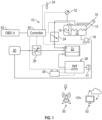
- The disclosure can be further understood by reference to the following detailed description when considered in connection with the accompanying drawings wherein:
-
Figure 1 schematically illustrates portions of one example evaporative fuel system. -
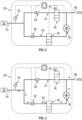
Figure 2 is a schematic view of the LDM inFigure 1 with in a non-operational state. -
Figure 3 is a schematic view of the LDM inFigure 1 with in a vacuum mode during a testing state. -
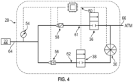
Figure 4 is a schematic view of the LDM inFigure 1 with in a pressure-hold mode during the testing state. -
Figure 5 is an example graph of hydrocarbon concentration based upon a voltage from a sensor in the LDM. - The embodiments, examples and alternatives of the preceding paragraphs, the claims, or the following description and drawings, including any of their various aspects or respective individual features, may be taken independently or in any combination. Features described in connection with one embodiment are applicable to all embodiments, unless such features are incompatible. Like reference numbers and designations in the various drawings indicate like elements.
-
Figure 1 schematically illustrates a portion of an exampleevaporative fuel system 10 of CN IV and CN V vehicles. It should be understood that other types of systems may be used. Thesystem 10 includes afuel tank 12 having afuel filler 14 with afill cap 16. Afuel pump 18 supplies gasoline, for example, from thefuel tank 12 to aninternal combustion engine 20, which provides propulsion to a vehicle. Afuel level sensor 15 is in communication with acontroller 40, which may be an engine controller, and measures a level of fuel within thefuel tank 12. - The
system 10 is configured to capture and regulate the flow of fuel vapors within the system. In one example type of system (e.g. those used in hybrid vehicles), a fuel tank isolation valve (FTIV) 24 is arranged fluidly between thefuel tank 12 and acharcoal canister 22, which captures and stores fuel vapors for later use by theengine 20. Apurge valve 26 is fluidly connected between thecanister 22 and theengine 20. In one example, thecontroller 40 regulates a position of thepurge valve 26 during engine operation in response to a purge command from theengine controller 40, for example, to selectively provide the fuel vapors to theengine 20 during fuel combustion to make use of these fuel vapors. The LDM 28 may also have its own controller separate and discrete from theengine controller 40. - Regarding the evaporative emissions system, the integrity of the
system 10 must be periodically tested to ensure no fuel vapor leakage. One type ofsystem 10 uses a leak detection module (LDM) 28 (also referred to as a "leak check module"), which can be used to pull a vacuum and/or pressurize the system to determine whether a leak exists, for example, using a pressure transducer (e.g., within the LDM 28). In one example leak test procedure, thepurge valve 26 is closed and theleak detection module 28 is used to evacuate or pressurize the system. Anotherpressure transducer 54 may be used to monitor the pressure of fuel vapors within thefuel tank 12 during other conditions. In one example, atemperature sensor 34 is arranged outside theLDM 28. Thetemperature sensor 34 may be useful for quantify heat transfer characteristics of the fuel vapor within thefuel tank 12 relative to surrounding atmospheric temperature. - A modified
LDM 28 is installed in thesystem 10. The working power supply of theLDM 28 is provided by avehicle power supply 48. The result data of theLDM 28 passes through thecommunication base station 50, which uploads to cloudstorage data center 52. The disclosedinventive LDM 28 can be independently installed on CN IV and CN V vehicles to conduct leakage inspections of the fuel evaporation control system and excessive HC compound emission inspections from thecarbon canisters 28. At the same time, results can be uploaded to the data center. The disclosedLDM 28 has the ability to independently monitor the status of the vehicle's fuel evaporation control system, independently start the diagnostic process, and independently determine whether it is leaking or exceeding the standard. - A disclosed
example LDM 28 is shown inFigures 2-4 . TheLDM 28 includes a pump 30 (e.g., a vane pump) rotationally driven by an electric motor and arranged in a common housing 46, which is typically provided by a multi-piece plastic structure. The housing 46 typically has two fluid connections or openings: acharcoal canister port 64 fluidly connected to thecharcoal canister 22, and an atmospheric port 66 in fluid communication with the atmosphere. A filter 31 (Fig. 1 ) may be arranged between the atmosphere and thepump 30 to prevent debris from entering theLDM 28. - Some customers prefer a system that operates using a vacuum, while other customers prefer a system that is pressurized. The rotational direction of the
pump 30 determines whether the system is pressurized or a vacuum is applied. So, to provide a pressurized evaporative emissions system test, thepump 30 will draw air from the atmospheric port 66 direct the atmospheric air towards thecharcoal canister 22. To provide a depressurized or negative pressure evaporative emissions system test (i.e., vacuum), thepump 30 will draw air from thecharcoal canister 22 and out to the atmosphere through the atmospheric port 66. - A canister valve solenoid (CVS)
CVS 36 is arranged in fluid communication along afirst fluid passageway 61 fluidly connected between the canister andatmospheric ports 64, 66. Asecond fluid passageway 62 also fluidly connects the canister andatmospheric ports 64, 66. Thepump 30 is arranged in fluid communication along thesecond fluid passageway 62 between the first andsecond ports 64, 66. ACVS check valve 38 is arranged in thesecond fluid passageway 62 and selectively blocks thecanister 22 from thepump 30 and atmosphere via the second port 66. - Generally, when the
LDM 28 is not performing a leak check of thefuel system 10, theCVS 36 and theCVS check valve 38, which are arranged in the housing 46, are in an open position to allow air to pass between thecharcoal canister port 64 and the atmospheric port 66. This enables thesystem 10 to draw air from the atmosphere (e.g., during vapor purge) or expel air to the atmosphere (e.g., during refueling), as needed. In the example, the first andsecond solenoid valves LDM 28 is performing a leak test of the of thefuel system 10, theCVS 36 is in a closed position, and theCVS check valve 38 remains in the open position. Once the desired system pressure is reached, both theCVS 36 andCVS check valve 38 are closed. Thepressure transducer 32 is arranged to read the pressure in the system. - The disclosed
LDM 28 has two functional aspects. First, theLDM 28 is operable to detect leaks in theevaporative emissions system 10, which is typical function of such a device. Second, theLDM 28 is also designed to determine the overall functionality of the emissions system itself and its effectiveness in mitigating undesired emissions (e.g., volatile organic compounds (VOCs)). To that end, the disclosedLDM 28 additionally includes apressure sensor 54, aVOC gas sensor 56, amass flow sensor 58, and acontroller 60. TheVOC gas sensor 56 can measure the concentration of hydrocarbons (HC). Themass flow sensor 58 is a bidirectional mass flow meter and can sense the direction of air flow. Thecontroller 60 includes data processing, device control, and wireless data transmission functions. - Regarding the leak detection function, the
LDM 28 includes three operational states including first state corresponding to a non-operational state in which both the first andsecond solenoid valves Fig. 2 ). In the example, theCVS 36 andCVS check valve 38 are 2-position valves having open and closed positions, and are spring-biased normally open when the solenoid valves are de-energized. This enables thesystem 10 to draw air from the atmosphere (e.g., during vapor purge) or expel air to the atmosphere (e.g., during refueling), as needed. No leak check is actively performed in this state. - In a second state (a pressure mode during a testing state), when the
LDM 28 receives a leakage diagnosis request, the timer of thecontroller 60 records that T0 time has passed since the last diagnosis. Once the conditions for re-diagnosis are verified as being satisfied, theLDM 28 starts the leakage diagnosis. Thefirst solenoid valve 36 is closed and thesecond solenoid valve 38 is open (Fig. 3 ). In this second state, thepump 30 is configured to move fluid between the canister andatmospheric ports 64, 66 to evacuate the air from thefuel system 10. - A third state (
Fig. 4 ) corresponds to a pressure-hold mode during the testing state in which the pressure sensor 54 (and/or pressure sensor 32) detects the relative pressure in thesystem 10. When the pressure in the system reaches the target threshold P0 (for example, -3kPa), thecontroller 60 turns off thepump 30. Both the first andsecond solenoid valves system 10. The internal pressure of the system is monitored for leaks. The pressure sensor 54 (and/or pressure sensor 32) monitors the relationship curve of the established system negative pressure vacuum P1 with time T1. Thecontroller 60 determines the leakage of the system through an algorithm and generates a result code. AnOBDII system 42 communicates and/or is integrated with theengine controller 40 and uses the pressure information to generate engine malfunction codes that may be stored and for illuminating a "check engine" light on the vehicle instrument panel indicating vehicle service is needed. After the leakage diagnosis is completed, thecontroller 60 de-energizes theCVS 36 andCVS check valve 38 to return them to the open positions. At the same time, thecontroller 60 uploads the diagnosis results to thedata center 52 via thecommunication base station 50 for storage. - The
LDM 28 evaluates the quality of emissions by obtaining the flow signal from thecarbon canister port 64 to the atmosphere port 66 through theflow sensor 58 during an emissions discharge. Thecontroller 60 records the time from the last flow signal to the current time, and determines that the carbon canister desorption has been completed and the standby time has been met. Next, theVOC gas sensor 56 detects the ppm concentration value of HC compounds escaping through thecharcoal canister 22 during T2, and converts it into an AD output signal (in volts) to thecontroller 60. An example graph of such values is shown inFigure 5 . Thecontroller 60 compares the measured value of the HC compound concentration with the threshold value, determines whether it exceeds the standard, and generate a result code. Thecontroller 60 then uploads the diagnosis results to thedata center 52 via thecommunication base station 50 for storage. - The
controller 40,controller 60 andOBDII system 42 may be integrated or separate. In terms of hardware architecture, such the controllers can include a processor, memory, and one or more input and/or output (I/O) device interface(s) that are communicatively coupled via a local interface. The local interface can include, for example but not limited to, one or more buses and/or other wired (e.g., CAN, LIN and/or LAN) or wireless connections. The local interface may have additional elements, which are omitted for simplicity, such as controllers, buffers (caches), drivers, repeaters, and receivers to enable communications. Further, the local interface may include address, control, and/or data connections to enable appropriate communications among the aforementioned components. - The controllers may be a hardware device for executing software, particularly software stored in memory. The processor can be a custom made or commercially available processor, a central processing unit (CPU), an auxiliary processor among several processors associated with the controllers, a semiconductor based microprocessor (in the form of a microchip or chip set) or generally any device for executing software instructions.
- The memory can include any one or combination of volatile memory elements (e.g., random access memory (RAM, such as DRAM, SRAM, SDRAM, VRAM, etc.)) and/or nonvolatile memory elements (e.g., ROM, etc.). Moreover, the memory may incorporate electronic, magnetic, optical, and/or other types of storage media. The memory can also have a distributed architecture, where various components are situated remotely from one another, but can be accessed by the controller.
- The software in the memory may include one or more separate programs, each of which includes an ordered listing of executable instructions for implementing logical functions. A system component embodied as software may also be construed as a source program, executable program (object code), script, or any other entity comprising a set of instructions to be performed. When constructed as a source program, the program is translated via a compiler, assembler, interpreter, or the like, which may or may not be included within the memory.
- When the controllers are in operation, its processor can be configured to execute software stored within the memory, to communicate data to and from the memory, and to generally control operations of the computing device pursuant to the software. Software in memory, in whole or in part, is read by the processor, perhaps buffered within the processor, and then executed.
- Through the combination of
pressure sensor 54,VOC gas sensor 56,mass flow sensor 58,controller 60, in addition to the commonly used normallyopen CVS 36, normally openCVS check valve 38, and pump 30, the existing CN IV and CN V vehicles can be monitored. Thefuel evaporation system 10 performs leakage diagnosis and HC emission diagnosis. The built-incontroller 60 of theLDM 28 can independently monitor the status of the vehicle's fuel evaporation control system, independently start the diagnostic process, independently determine whether there is leakage or exceed the standard, and upload the determination results to a remote data center. - It should also be understood that although a particular component arrangement is disclosed in the illustrated embodiment, other arrangements will benefit herefrom. Although particular step sequences are shown, described, and claimed, it should be understood that steps may be performed in any order, separated or combined unless otherwise indicated and will still benefit from the present invention.
- Although the different examples have specific components shown in the illustrations, embodiments of this invention are not limited to those particular combinations. It is possible to use some of the components or features from one of the examples in combination with features or components from another one of the examples. For example, the disclosed pump may be used in applications other than vehicle evaporative systems.
- Although an example embodiment has been disclosed, a worker of ordinary skill in this art would recognize that certain modifications would come within the scope of the claims. For that reason, the following claims should be studied to determine their true scope and content.
Claims (5)
- A leak detection module (LDM) (28) comprising:a housing (46);a canister valve solenoid (CVS) (36) arranged within the housing (46) and in fluid communication along a first fluid passageway (61) between canister and atmospheric ports (64, 66), the CVS (36) movable between open and closed positions;a second fluid passageway (62) in parallel with the first fluid passageway (61) and fluidly connected to the canister and atmospheric ports (64, 66);a pump (30) arranged in the second fluid passageway (62);a CVS check valve (38) arranged in the second fluid passageway (62) fluidly and movable between open and closed positions;a pressure sensor (54) in fluid communication with the canister port (64);a volatile organic compound (VOC) gas sensor (56) arranged in one of the first and second passageways (61, 62) and configured to measure the concentration of hydrocarbons (HC) therethrough;a mass flow meter (58) arranged in one of the first and second passageways (61, 62) to determine a mass flow rate from the canister port (64) to the atmospheric port (66); anda controller (60) arranged in the housing (46) and in communication with the pump (30), the CVS (36), the CVS check valve (38), the pressure sensor (54), the VOC gas sensor (56), the mass flow meter (58), the controller (60) configured to run a leak detection procedure using the pump (30) and operating the CVS (36) and CVS check valve (38) between the open and closed positions and monitor a pressure within the LDM (28) with the pressure sensor (54), and the controller (60) configured to measure quality of emissions by monitoring the HC and communicate a result.
- The LDM (28) of claim 1, wherein the CVS (36) and CVS check valve (38) are 2-position valves having open and closed positions, wherein the leak detection procedure includes three operational states, comprising:non-operational state in which both the CVS (36) and CVS check valve (38) are open;a pressure mode during a testing state in which the CVS (36) is closed and the CVS check valve (38) is open, the CVS (36) fluidly blocking the fluid flow between the charcoal canister port (64) and the atmospheric port (66), and the pump (30) is configured to move fluid between the canister and atmospheric ports (64, 66); anda pressure-hold mode during the testing state in which the both the CVS (36) and CVS check valve (38) are closed.
- The LDM (28) of claim 1 or 2, wherein the controller (60) determines the quality of emissions by obtaining the mass flow rate signal from carbon canister to the atmosphere port (66) during an emissions discharge, recording a time from the last flow signal to the current time and determines that the carbon canister desorption has been completed and the standby time has been met, detecting the HC ppm concentration value escaping through the canister port (64) during T2, and comparing the HC ppm concentration with the threshold value to determine whether it exceeds a standard in order to provide the result.
- The LDM (28) of claim 3, wherein the controller (60) is configured to wirelessly upload the result to a data center (52) via a base station (50) for storage.
- An evaporative emissions system (10) comprising the LDM (28) of any preceding claim, the system (10) comprising:an engine (20) configured to provide vehicle propulsion;a fuel tank (12) configured to contain fuel and fuel vapors selectively supplied to the engine (20);a charcoal canister (22) configured to store the fuel vapors from the fuel tank (12), the canister port (64) in fluid communication with the charcoal canister (22);a fuel tank isolation valve (24) fluidly provided between fuel tank (12) and the charcoal canister (22);a purge valve (26) in fluid communication with the charcoal canister (22) and configured to selectively provide the fuel vapors to an engine (20) in response to a purge command.
Applications Claiming Priority (1)
| Application Number | Priority Date | Filing Date | Title |
|---|---|---|---|
| CN202323663408 | 2023-12-29 |
Publications (1)
| Publication Number | Publication Date |
|---|---|
| EP4579074A1 true EP4579074A1 (en) | 2025-07-02 |
Family
ID=94116937
Family Applications (1)
| Application Number | Title | Priority Date | Filing Date |
|---|---|---|---|
| EP24223102.5A Pending EP4579074A1 (en) | 2023-12-29 | 2024-12-23 | Evaporative emissions leak check module with volatile organic compound measurement |
Country Status (3)
| Country | Link |
|---|---|
| US (1) | US20250215845A1 (en) |
| EP (1) | EP4579074A1 (en) |
| CN (1) | CN120231657A (en) |
Citations (3)
| Publication number | Priority date | Publication date | Assignee | Title |
|---|---|---|---|---|
| US20160084175A1 (en) * | 2014-09-24 | 2016-03-24 | Ford Global Technologies, Llc | Systems and methods for reducing bleed emissions |
| US9944175B2 (en) * | 2013-05-24 | 2018-04-17 | Continental Automotive Gmbh | Fuel tank system |
| US20230313762A1 (en) * | 2020-09-15 | 2023-10-05 | Stoneridge Control Devices, Inc. | Leak detection module entropy method for evaporative emissions system |
-
2024
- 2024-12-23 US US18/999,073 patent/US20250215845A1/en active Pending
- 2024-12-23 EP EP24223102.5A patent/EP4579074A1/en active Pending
- 2024-12-27 CN CN202411950885.1A patent/CN120231657A/en active Pending
Patent Citations (3)
| Publication number | Priority date | Publication date | Assignee | Title |
|---|---|---|---|---|
| US9944175B2 (en) * | 2013-05-24 | 2018-04-17 | Continental Automotive Gmbh | Fuel tank system |
| US20160084175A1 (en) * | 2014-09-24 | 2016-03-24 | Ford Global Technologies, Llc | Systems and methods for reducing bleed emissions |
| US20230313762A1 (en) * | 2020-09-15 | 2023-10-05 | Stoneridge Control Devices, Inc. | Leak detection module entropy method for evaporative emissions system |
Also Published As
| Publication number | Publication date |
|---|---|
| US20250215845A1 (en) | 2025-07-03 |
| CN120231657A (en) | 2025-07-01 |
Similar Documents
| Publication | Publication Date | Title |
|---|---|---|
| JP3614433B2 (en) | Canister purge system with positive pressure diagnostic device | |
| JP3599196B2 (en) | Positive pressure diagnostic device for a canister purge device for a vehicle having an internal heat engine and method for diagnosing unacceptable leaks from parts of the canister purge device | |
| RU2547545C2 (en) | Vehicle (versions) | |
| JP3253994B2 (en) | Tank ventilation device and method of checking its airtightness | |
| US20160298576A1 (en) | System for Evaporative and Refueling Emission Control for a Vehicle | |
| US6845652B2 (en) | Method and device for diagnosing tank leaks using a reference measuring method | |
| JP2001115915A (en) | Leak diagnosis device for in-tank canister system | |
| US5560347A (en) | Conductive foam vapor sensing | |
| JP2004156493A (en) | Evaporative fuel processor for internal combustion engines | |
| JP2001304054A (en) | Failure diagnosis device for fuel vapor purge system | |
| US12276240B2 (en) | Leak detection module entropy method for evaporative emissions system | |
| JP4564221B2 (en) | In particular, a low-emission operation method and apparatus for an automobile fuel tank system | |
| US5651349A (en) | Purge system flow monitor and method | |
| US20100095747A1 (en) | Method and Device for Testing the Tightness of a Fuel Tank of an Internal Combustion Engine | |
| JP4021957B2 (en) | Method for detecting refueling process in container | |
| JPH0734987A (en) | A method for monitoring a tank ventilation system that collects fuel vapor and supplies it to an internal combustion engine. | |
| US20250215845A1 (en) | Evaporative emissions leak check module with voc measurement | |
| US11773809B2 (en) | Evaporative emissions leak check module with integrated control and communication system | |
| JP2000065671A (en) | Method for testing the functionality of containers, especially tank venting equipment | |
| US12553406B2 (en) | Evaporative emissions system vapor blocking valve leak diagnostic with a single pressure sensor | |
| WO2025174689A1 (en) | Leak detection module entropy method with variable speed pump for evaporative emissions system | |
| KR102730572B1 (en) | Method and device for diagnosing fuel evaporation retention system of internal combustion engine | |
| JP2005291122A (en) | Failure diagnosis method and failure diagnosis apparatus for evaporative fuel processing apparatus for automobile | |
| US20260056084A1 (en) | Evaporative emissions leak detection module | |
| US20250215843A1 (en) | Evaporative emissions leak check module with proportional solenoid valve |
Legal Events
| Date | Code | Title | Description |
|---|---|---|---|
| PUAI | Public reference made under article 153(3) epc to a published international application that has entered the european phase |
Free format text: ORIGINAL CODE: 0009012 |
|
| STAA | Information on the status of an ep patent application or granted ep patent |
Free format text: STATUS: THE APPLICATION HAS BEEN PUBLISHED |
|
| AK | Designated contracting states |
Kind code of ref document: A1 Designated state(s): AL AT BE BG CH CY CZ DE DK EE ES FI FR GB GR HR HU IE IS IT LI LT LU LV MC ME MK MT NL NO PL PT RO RS SE SI SK SM TR |
|
| STAA | Information on the status of an ep patent application or granted ep patent |
Free format text: STATUS: REQUEST FOR EXAMINATION WAS MADE |
|
| 17P | Request for examination filed |
Effective date: 20251223 |