EP4579072A1 - Methanol injection control method, methanol injection system, and vehicle - Google Patents
Methanol injection control method, methanol injection system, and vehicle Download PDFInfo
- Publication number
- EP4579072A1 EP4579072A1 EP24826863.3A EP24826863A EP4579072A1 EP 4579072 A1 EP4579072 A1 EP 4579072A1 EP 24826863 A EP24826863 A EP 24826863A EP 4579072 A1 EP4579072 A1 EP 4579072A1
- Authority
- EP
- European Patent Office
- Prior art keywords
- fuel
- methanol
- injection
- fuel injector
- pressure
- Prior art date
- Legal status (The legal status is an assumption and is not a legal conclusion. Google has not performed a legal analysis and makes no representation as to the accuracy of the status listed.)
- Pending
Links
Images


Classifications
-
- F—MECHANICAL ENGINEERING; LIGHTING; HEATING; WEAPONS; BLASTING
- F02—COMBUSTION ENGINES; HOT-GAS OR COMBUSTION-PRODUCT ENGINE PLANTS
- F02D—CONTROLLING COMBUSTION ENGINES
- F02D41/00—Electrical control of supply of combustible mixture or its constituents
- F02D41/30—Controlling fuel injection
- F02D41/3094—Controlling fuel injection the fuel injection being effected by at least two different injectors, e.g. one in the intake manifold and one in the cylinder
-
- F—MECHANICAL ENGINEERING; LIGHTING; HEATING; WEAPONS; BLASTING
- F02—COMBUSTION ENGINES; HOT-GAS OR COMBUSTION-PRODUCT ENGINE PLANTS
- F02D—CONTROLLING COMBUSTION ENGINES
- F02D19/00—Controlling engines characterised by their use of non-liquid fuels, pluralities of fuels, or non-fuel substances added to the combustible mixtures
- F02D19/06—Controlling engines characterised by their use of non-liquid fuels, pluralities of fuels, or non-fuel substances added to the combustible mixtures peculiar to engines working with pluralities of fuels, e.g. alternatively with light and heavy fuel oil, other than engines indifferent to the fuel consumed
- F02D19/0639—Controlling engines characterised by their use of non-liquid fuels, pluralities of fuels, or non-fuel substances added to the combustible mixtures peculiar to engines working with pluralities of fuels, e.g. alternatively with light and heavy fuel oil, other than engines indifferent to the fuel consumed characterised by the type of fuels
- F02D19/0649—Liquid fuels having different boiling temperatures, volatilities, densities, viscosities, cetane or octane numbers
- F02D19/0652—Biofuels, e.g. plant oils
- F02D19/0655—Biofuels, e.g. plant oils at least one fuel being an alcohol, e.g. ethanol
-
- F—MECHANICAL ENGINEERING; LIGHTING; HEATING; WEAPONS; BLASTING
- F02—COMBUSTION ENGINES; HOT-GAS OR COMBUSTION-PRODUCT ENGINE PLANTS
- F02D—CONTROLLING COMBUSTION ENGINES
- F02D41/00—Electrical control of supply of combustible mixture or its constituents
- F02D41/0025—Controlling engines characterised by use of non-liquid fuels, pluralities of fuels, or non-fuel substances added to the combustible mixtures
-
- F—MECHANICAL ENGINEERING; LIGHTING; HEATING; WEAPONS; BLASTING
- F02—COMBUSTION ENGINES; HOT-GAS OR COMBUSTION-PRODUCT ENGINE PLANTS
- F02M—SUPPLYING COMBUSTION ENGINES IN GENERAL WITH COMBUSTIBLE MIXTURES OR CONSTITUENTS THEREOF
- F02M69/00—Low-pressure fuel-injection apparatus ; Apparatus with both continuous and intermittent injection; Apparatus injecting different types of fuel
- F02M69/04—Injectors peculiar thereto
- F02M69/042—Positioning of injectors with respect to engine, e.g. in the air intake conduit
- F02M69/046—Positioning of injectors with respect to engine, e.g. in the air intake conduit for injecting into both the combustion chamber and the intake conduit
-
- F—MECHANICAL ENGINEERING; LIGHTING; HEATING; WEAPONS; BLASTING
- F02—COMBUSTION ENGINES; HOT-GAS OR COMBUSTION-PRODUCT ENGINE PLANTS
- F02D—CONTROLLING COMBUSTION ENGINES
- F02D2200/00—Input parameters for engine control
- F02D2200/02—Input parameters for engine control the parameters being related to the engine
- F02D2200/06—Fuel or fuel supply system parameters
- F02D2200/0602—Fuel pressure
-
- F—MECHANICAL ENGINEERING; LIGHTING; HEATING; WEAPONS; BLASTING
- F02—COMBUSTION ENGINES; HOT-GAS OR COMBUSTION-PRODUCT ENGINE PLANTS
- F02D—CONTROLLING COMBUSTION ENGINES
- F02D2200/00—Input parameters for engine control
- F02D2200/02—Input parameters for engine control the parameters being related to the engine
- F02D2200/10—Parameters related to the engine output, e.g. engine torque or engine speed
- F02D2200/1002—Output torque
-
- F—MECHANICAL ENGINEERING; LIGHTING; HEATING; WEAPONS; BLASTING
- F02—COMBUSTION ENGINES; HOT-GAS OR COMBUSTION-PRODUCT ENGINE PLANTS
- F02M—SUPPLYING COMBUSTION ENGINES IN GENERAL WITH COMBUSTIBLE MIXTURES OR CONSTITUENTS THEREOF
- F02M2200/00—Details of fuel-injection apparatus, not otherwise provided for
- F02M2200/95—Fuel injection apparatus operating on particular fuels, e.g. biodiesel, ethanol, mixed fuels
Definitions
- methanol engine Since the air-fuel ratio of methanol is 6.5, which is about half of that of gasoline. Relative to a gasoline engine, under the same intake theoretical air-fuel ratio conditions, the injection amount of methanol is twice that of gasoline. In order to avoid too long injection pulse width and to increase injection rate, methanol engine usually adopts large flow methanol fuel injector. Although large flow fuel injector solves the problem of injection volume, methanol fuel needs more energy to vaporize because methanol requires more energy to evaporate per unit mass than gasoline, so that methanol entering the combustion chamber cannot be atomized well, which deteriorates the starting performance of the engine in low temperature environment and leads to poor low temperature starting performance of methanol engine.
- the main purpose of the present application is to provide a methanol injection control method, a methanol injection system and a vehicle, aiming to solve the problem of poor low temperature starting performance of existing methanol engines.
- the present application provides a methanol injection control method, applied to a methanol injection system.
- the methanol injection system includes an injection structure and a control apparatus.
- the injection structure includes a first fuel injector and a second fuel injector.
- the first fuel injector is provided in a cylinder of a methanol engine, and the second fuel injector is provided in an intake pipeline of a methanol engine.
- the control apparatus is electrically connected to the injection structure.
- the methanol injection control method is applied to the control apparatus.
- the methanol injection control method includes the following steps:
- the determining the first mixed injection ratio according to the required power parameter includes:
- the first fuel injector is provided at a sidewall of the cylinder; and the determining the injection strategy according to the required power parameter, and controlling the injection of the first fuel injector and/or the second fuel injector according to the injection strategy includes:
- the in response to that the required power parameter is greater than or equal to the first preset threshold value, determining the second mixed injection ratio according to the required power parameter, and controlling the first fuel injector and the second fuel injector to inject methanol simultaneously according to the second mixed injection ratio includes:
- the fuel supply pipeline includes a fuel supply main pipe communicated with the methanol tank and a first fuel supply branch pipe and a second fuel supply branch pipe communicated with the fuel supply main pipe, a tail end of the first fuel supply branch pipe is communicated with the first fuel injector, a tail end of the second fuel supply branch pipe is communicated with the second fuel injector, and the power apparatus includes a first fuel pump provided at the fuel supply main pipe and a second fuel pump provided at the first fuel supply branch pipe; and the determining the supply strategy according to the first actual fuel pressure and/or the second actual fuel pressure, and controlling the fuel supply of the power apparatus according to the supply strategy includes:
- the present application provides a methanol injection system, including:
- a fuel pressure of the first fuel injector is P1
- a fuel pressure of the second fuel injector is P2
- P1 is not less than 100 bar
- P2 is not less than 100 bar.
- a fuel pressure of the first fuel injector is P1
- a fuel pressure of the second fuel injector is P2
- P1 is not less than 100 bar
- P2 is less than 100 bar.
- P1 is not less than 200bar and not greater than 500 bar, and P2 is not greater than 20 bar.
- the methanol injection system further includes:
- a fuel pressure of the first fuel injector is P1
- a fuel pressure of the second fuel injector is P2
- P1 is not less than 100bar
- P2 is not less than 100bar
- the methanol injection system further includes a high-pressure fuel pump provided at the fuel supply main pipe and electrically connected to the control apparatus.
- the methanol injection system further includes a low-pressure fuel pump provided at the fuel supply main pipe and electrically connected to the control apparatus.
- a fuel pressure of the first fuel injector is P1
- a fuel pressure of the second fuel injector is P2
- P1 is not less than 100bar
- P2 is less than 100bar
- the methanol injection system further includes a high-pressure fuel pump provided at the first fuel supply branch pipe and electrically connected to the control apparatus.
- the methanol injection system further includes a low-pressure fuel pump provided at the fuel supply main pipe and electrically connected to the control apparatus.
- the methanol injection system further includes a high-pressure fuel pump provided at the first fuel supply branch pipe and electrically connected to the control apparatus.
- a plurality of first fuel injectors correspond to a plurality of cylinders of the methanol engine respectively; and/or a plurality of second fuel injectors correspond to the plurality of cylinders of the methanol engine.
- the methanol injection system further includes a fuel rail
- the methanol injection system further includes a rail pressure sensor provided at the fuel rail and electrically connected to the control apparatus.
- the methanol injection system further includes a methanol engine, the methanol engine includes a cylinder;
- the present application also provides a vehicle, including the methanol injection system.
- the required power parameter of the methanol engine is obtained so as to determine the injection strategy of the injection structure according to the required power parameter.
- the required power parameter is used to determine the injection ratio of the first fuel injector and the second fuel injector under different powers, so that the injection amounts of the first fuel injector and the second fuel injector can be adapted to the load of the methanol engine, which can not only ensure the output power of the methanol engine, but also reduce the probability of wall wetting in the methanol engine and reduce the energy required for methanol vaporization, thereby effectively improving the atomization effect of methanol, and helping to improve the cold start performance of the methanol engine.
- Reference sign name Reference sign name 100 methanol injection system 3 control apparatus 1 injection structure 4 low-pressure fuel pump 11 first fuel injector 5 high-pressure fuel pump 12 second fuel injector 6 fuel rail 2 fuel supply pipeline 7 rail pressure sensor 21 fuel supply main pipe 8 methanol tank 22 first fuel supply branch pipe 9 methanol engine 23 second fuel supply branch pipe 91 intake duct
- the air-fuel ratio of methanol is 6.5, which is about half of that of gasoline.
- the injection volume of methanol is twice that of gasoline under the same theoretical air-fuel ratio of intake volume.
- the methanol engine usually adopts large-flow methanol fuel injector.
- large-flow fuel injector solves the problem of injection volume, the energy required for methanol evaporation per unit mass is higher than that of the gasoline, and methanol fuel needs more energy to vaporize, so that the methanol entering the combustion chamber cannot be atomized well, which deteriorates the starting performance of the engine in a low-temperature environment and leads to poor low-temperature starting performance of the methanol engine.
- the methanol injection system 100 includes an injection structure 1 and a control apparatus 3, the injection structure 1 includes a first fuel injector 11 and a second fuel injector 12, the first fuel injector 11 is provided in the cylinder of the methanol engine 9, the second fuel injector 12 is provided at the intake pipeline of the methanol engine 9, and the control apparatus 3 is electrically connected to the first fuel injector 11 and the second fuel injector 12.
- the control apparatus 3 controls the second fuel injector 12 and the first fuel injector 11 to inject methanol at a first injection ratio so that the methanol engine 9 can operate at a medium load.
- the control apparatus 3 controls the first fuel injector 11 and the second fuel injector 12 to inject methanol at a second injection ratio so that the methanol engine 9 can operate at a high load.
- the first injection ratio is different from the second injection ratio. Specifically, the injection ratio can be adjusted as needed.
- the control apparatus 3 may include: a processor 1001, such as a CPU, a communication bus 1002, a user interface 1003, a network interface 1004, and a memory 1005.
- the communication bus 1002 is configured to realize the connection and communication between these components.
- the user interface 1003 may include a display screen, an input unit such as a keyboard, and the user interface 1003 may also include a standard wired interface and a wireless interface.
- the network interface 1004 may include a standard wired interface and a wireless interface (such as a WI-FI interface).
- the memory 1005 may be a high-speed RAM memory, or a non-volatile memory, such as a disk memory.
- the memory 1005 may also be a storage apparatus independent of the aforementioned processor 1001.
- the fuel pressure of the first fuel injector 11 is P1, and P1 is not less than 100bar, so that the high fuel pressure is helpful to improve the atomization effect of the first fuel injector, reduce the risk of wall wetting, and improve the cold start performance of the methanol engine 9.
- P1 is not less than 200bar and not greater than 500bar, which can not only improve the atomization effect of the first fuel injector 11, facilitate the full mixing of the gas, avoid wall wetting and improve the cold start performance, but also reduce the cost of the methanol injection system 100.
- the fuel pressure P1 of the first fuel injector 11 can be 250bar, 300bar, 350bar or 400bar, and of course can be any value in the above range, which is not limited in the present application. Specifically, P1 is not less than 200bar and not greater than 350bar.
- the fuel pressure of the second fuel injector 12 is P2, and P2 is less than 100bar. Since the second fuel injector 12 is outside the cylinder of the methanol engine 9, it is not easy to cause the wall wetting problem. Therefore, the second fuel injector 12 adopts a lower fuel pressure to reduce the cost of the methanol injection system 100.
- the fuel pressure P2 of the second fuel injector 12 can be 15bar, 35bar, 55bar or 80bar, and of course it can also be any value in the above range, which is not limited in the present application.
- P2 is not greater than 20bar, so as to adapt to the existing methanol fuel supply system, make use of the components in the existing methanol fuel supply system, thereby helping to reduce the cost of the methanol injection system 100.
- the fuel pressure of the first fuel injector and the fuel pressure of the second fuel injector are P1 and P2 respectively, and P1 is not less than 100bar, and P2 is not less than 100bar, so that the first fuel injector 11 and the second fuel injector 12 both use high-pressure injection to ensure the atomization effect of methanol, thereby facilitating the cold start performance of the methanol engine 9.
- the fuel pressure of the first fuel injector 11 and the fuel pressure of the second fuel injector 12 may be the same or different, as long as the fuel pressure of the first fuel injector 11 and the fuel pressure of the second fuel injector 12 are not less than 100bar, which is not limited in the present application.
- P is not less than 200bar and not greater than 500bar, which can not only improve the atomization effect of the first fuel injector 11 and the second fuel injector, facilitate the full mixing of the gas, avoid wall wetting and improve the cold start performance, but also reduce the cost of the methanol injection system 100.
- the fuel pressure P of the first fuel injector 11 and the second fuel injector 12 can be 250bar, 300bar, 350bar or 400bar, and of course it can be any value in the above range, which is not limited in the present application.
- P1 is not less than 200bar and not greater than 350bar.
- the fuel pressure of the first fuel injector and the fuel pressure of the second fuel injector are P1 and P2 respectively.
- P1 is not less than 100bar
- P2 is less than 100bar.
- the second fuel injector 12 Since the second fuel injector 12 is outside the cylinder of the methanol engine 9 and is not prone to wall wetting, the second fuel injector 12 uses a lower fuel pressure to reduce the cost of the methanol injection system 100.
- the first fuel injector 11 is inside the cylinder of the methanol engine 9 and is prone to wall wetting. Therefore, the first fuel injector 11 uses a higher fuel pressure to improve the atomization effect of the first fuel injector 11 and reduce the probability of wall wetting.
- P1 is not less than 200bar and not greater than 500bar, which not only can improve the atomization effect of the first fuel injector 11, facilitate the full mixing of the gas, avoid wall wetting and improve the high cold start performance, but can also reduce the cost of the methanol injection system 100.
- the fuel pressure P1 of the first fuel injector 11 can be 250bar, 300bar, 350bar or 400bar, and of course it can also be any value in the above range, which is not limited in the present application.
- P1 is not less than 200bar and not greater than 350bar.
- P2 is not greater than 20bar, so as to adapt to the existing methanol fuel supply system and make use of the components in the existing methanol fuel supply system, thereby helping to reduce the cost of the methanol injection system 100.
- the fuel pressure P2 of the second fuel injector 12 can be 15bar, 35bar, 55bar or 80bar, and of course it can also be any value in the above range, which is not limited in the present application.
- the methanol injection system 100 also includes a high-pressure fuel pump 5 provided at the first fuel supply branch pipe 22, and the high-pressure fuel pump 5 is electrically connected to the control apparatus 3.
- the high-pressure fuel pump 5 is provided to drive the methanol in the first fuel supply branch pipe 22 to flow to the first fuel injector 11.
- the high-pressure fuel pump 5 is electrically connected to the control apparatus 3, so that when the first fuel injector 11 injects methanol, the control apparatus 3 can control the high-pressure fuel pump 5 to synchronously replenish methanol to the first fuel injector 11.
- the first fuel injector 11 is provided at various positions. Specifically, in an embodiment, the first fuel injector 11 is provided at the top of the cylinder.
- the first fuel injector 11 and the second fuel injector 12 need to inject methanol according to the second injection ratio to avoid excessive injection amount of a single fuel injector.
- the injection ratio of the first injector and the second injector is determined by the required power parameter, so that the injection ratio and the injection amount of the injection structure 1 can be adapted to the load of the methanol engine 9.
- step S20 includes:
- the spray hole of the first fuel injector 11 is facing the cylinder barrel and is relatively top-mounted, which is more likely to cause wall wetting problems.
- the injection amount of the first fuel injector 11 is less than the injection amount of the second fuel injector 12, that is, the gas path injection is mainly used.
- the first preset threshold value may be a fixed value or a value range, etc., which is not limited in the present application.
- the first fuel injector 11 and the second fuel injector 12 are required to inject methanol at the same time to ensure that the injection amount of the injection structure 1 can match the load of the methanol engine 9, and the injection amount of the second fuel injector 12 is greater than the injection amount of the first fuel injector 11.
- step S24 includes:
- the required power parameter when the required power parameter is greater than or equal to the first preset threshold value and less than the second preset threshold value, it means that the load of the methanol engine 9 is medium load, and the injection amount of the injection structure 1 is medium.
- the first fuel injector 11 and the second fuel injector 12 inject methanol according to the third injection ratio, mainly with the second fuel injector 12.
- the required power parameter is greater than or equal to the second preset threshold value, it means that the load of the methanol engine 9 is high load, and the injection amount of the injection structure 1 is the largest.
- the first fuel injector 11 and the second fuel injector 12 still inject methanol according to the third injection ratio, the injection amount of the second fuel injector 12 will be too large, which may easily cause the wall wetting. Therefore, the first fuel injector 11 and the second fuel injector 12 need to be injected methanol according to the fourth injection ratio to avoid excessive injection amount of a single fuel injector.
- the injection ratio of the first injector and the second injector is determined by the required power parameter, so that the injection ratio and the injection amount of the injection structure 1 can be adapted to the load of the methanol engine 9.
- the third injection ratio and the fourth injection ratio both refer to the ratio of the injection amount of the first fuel injector 11 to the injection amount of the second fuel injector 12.
- the second preset threshold value can be a fixed value or a value range, etc., which is not limited in the present application. In reality, taking the first preset threshold value as 25% and the second preset threshold value as 50% for an example.
- the required power parameter is 40%, it means that the load of the methanol engine 9 is medium, and the injection amount of the injection structure 1 is medium.
- the first fuel injector 11 and the second fuel injector 12 inject methanol according to the third injection ratio, mainly with the second fuel injector 12.
- the required power parameter is 60%, it means that the load of the methanol engine 9 is high and the injection amount of the injection structure 1 is the largest.
- the first fuel injector 11 and the second fuel injector 12 inject methanol according to the fourth injection ratio, so that the first fuel injector 11 can share the injection amount of the injection structure 1, which can match the injection amount of the injection structure 1 with the load of the methanol engine, and avoid excessive injection amount of a single fuel injector, thereby helping to avoid the wall wetting problem of the methanol engine.
- the third injection ratio and the fourth injection ratio are not limited and can be adjusted as needed.
- the injection amount of the first fuel injector 11 accounts for 20% to 35% of the total injection amount
- the injection amount of the second fuel injector 12 accounts for 65% to 80% of the total injection amount.
- the methanol engine 9 is in medium load
- the injection amount of the injection structure 1 is medium. Since the first fuel injector 11 is provided at the sidewall of the cylinder, the wall wetting problem is likely to occur. Therefore, the second fuel injector 12 is mainly used to inject methanol to avoid the wall wetting problem of the methanol engine 9.
- the injection amount of the first fuel injector 11 accounts for 40% to 50% of the total injection amount
- the injection amount of the second fuel injector 12 accounts for 50% to 60% of the total injection amount.
- the methanol engine 9 is at a high load, and the injection amount of the injection structure 1 is large.
- the injection amount of the first fuel injector 11 needs to be increased to share the injection amount of the injection structure 1, thereby helping to avoid the wall wetting problem of the methanol engine 9.
- the methanol injection system further includes a methanol tank, a fuel supply pipeline and a power apparatus.
- the inlet of the fuel supply pipeline is communicated with the methanol tank
- the outlet of the fuel supply pipeline is communicated with the first fuel injector 11 and the second fuel injector 12 respectively
- the power apparatus is provided at the fuel supply pipeline and electrically connected to the control apparatus.
- the methanol injection control method further includes the following steps :
- the first actual fuel pressure and the second actual fuel pressure are obtained to determine the methanol supply strategy of the first fuel injector 11 and the second fuel injector 12. Thus, whether it is necessary to supply methanol to the first fuel injector 11 and the second fuel injector 12 is determined by the first actual fuel pressure and the second actual fuel pressure, so as to control the power apparatus to supply methanol to the first fuel injector 11 and the second fuel injector 12 in time.
- the fuel supply pipeline includes a fuel supply main pipe communicated with the methanol tank and a first fuel supply branch pipe and a second fuel supply branch pipe communicated with the fuel supply main pipe.
- a tail end of the first fuel supply branch pipe is communicated with the first fuel injector 11
- a tail end of the second fuel supply branch pipe is communicated with the second fuel injector 12, and the power apparatus is provided at the fuel supply main pipe.
- Step S40 includes: in response to that the first actual fuel pressure is less than the first preset fuel pressure, and/or the second actual fuel pressure is less than the first preset fuel pressure, the power apparatus works until the first actual fuel pressure and the second actual fuel pressure are not less than the first preset fuel pressure.
- the power apparatus is controlled to work so as to replenish methanol for the first fuel injector 11 and the second fuel injector 12. In this way, by obtaining the first actual fuel pressure and the second fuel pressure, the power apparatus is controlled to replenish methanol for the first fuel injector 11 and the second fuel injector 12 in time.
- the fuel pressure of the first fuel injector 11 and the fuel pressure of the second fuel injector 12 are the same.
- the first preset fuel pressure can be a fixed value or a value range, etc., which is not limited in the present application. In reality, taking the first preset fuel pressure as 200bar for an example, if the first actual fuel pressure is less than 200bar, it means that the first fuel injector 11 is injecting methanol and needs to be replenished with methanol. At this time, the power apparatus works to replenish methanol for the first fuel injector 11. If the second actual fuel pressure is less than 200bar, it means that the second fuel injector 12 is injecting methanol and needs to be replenished with methanol. At this time, the power apparatus works to replenish methanol for the second fuel injector 12. That is, no matter whether the first actual fuel pressure decreases or the second actual fuel pressure decreases, the power apparatus needs to work.
Landscapes
- Engineering & Computer Science (AREA)
- Chemical & Material Sciences (AREA)
- Combustion & Propulsion (AREA)
- Mechanical Engineering (AREA)
- General Engineering & Computer Science (AREA)
- Biodiversity & Conservation Biology (AREA)
- Life Sciences & Earth Sciences (AREA)
- Biotechnology (AREA)
- Botany (AREA)
- Sustainable Development (AREA)
- Sustainable Energy (AREA)
- Oil, Petroleum & Natural Gas (AREA)
- Electrical Control Of Air Or Fuel Supplied To Internal-Combustion Engine (AREA)
- Fuel-Injection Apparatus (AREA)
Abstract
Disclosed are a methanol injection control method, a methanol injection system (100) and a vehicle. The methanol injection control method is applied to the methanol injection system (100). The methanol injection system (100) includes a cylinder communicated with an intake pipeline and an injection structure (1). The injection structure (1) includes a first fuel injector (11) provided in the cylinder and a second fuel injector (12) provided at the intake pipeline. The methanol injection control method includes: (S10), obtaining a required power parameter of the methanol engine; and (S20), determining an injection strategy according to the required power parameter, and controlling an injection of the first fuel injector (11) and/or the second fuel injector (12) according to the injection strategy, so that the injection volume of the first injector (11) and the second injector (12) can be adapted to the load of the methanol engine.
Description
- The present application claims priority to
Chinese Patent Application No. 202322868055.1, filed on October 24, 2023 Chinese Patent Application No. 202322873383.0, filed on October 24, 2023 Chinese Patent Application No. 202311391716.4, filed on October 24, 2023 - The present application relates to the technical field of methanol injection, and in particular to a methanol injection control method, a methanol injection system and a vehicle.
- Since the air-fuel ratio of methanol is 6.5, which is about half of that of gasoline. Relative to a gasoline engine, under the same intake theoretical air-fuel ratio conditions, the injection amount of methanol is twice that of gasoline. In order to avoid too long injection pulse width and to increase injection rate, methanol engine usually adopts large flow methanol fuel injector. Although large flow fuel injector solves the problem of injection volume, methanol fuel needs more energy to vaporize because methanol requires more energy to evaporate per unit mass than gasoline, so that methanol entering the combustion chamber cannot be atomized well, which deteriorates the starting performance of the engine in low temperature environment and leads to poor low temperature starting performance of methanol engine.
- The main purpose of the present application is to provide a methanol injection control method, a methanol injection system and a vehicle, aiming to solve the problem of poor low temperature starting performance of existing methanol engines.
- To achieve the above objective, the present application provides a methanol injection control method, applied to a methanol injection system. The methanol injection system includes an injection structure and a control apparatus. The injection structure includes a first fuel injector and a second fuel injector. The first fuel injector is provided in a cylinder of a methanol engine, and the second fuel injector is provided in an intake pipeline of a methanol engine. The control apparatus is electrically connected to the injection structure. The methanol injection control method is applied to the control apparatus. The methanol injection control method includes the following steps:
- obtaining a required power parameter of the methanol engine; and
- determining an injection strategy according to the required power parameter, and controlling an injection of the first fuel injector and/or the second fuel injector according to the injection strategy.
- In an embodiment, the first fuel injector is provided at a top of the cylinder; and
the determining the injection strategy according to the required power parameter, and controlling the injection of the first fuel injector and/or the second fuel injector according to the injection strategy includes: - in response to that the required power parameter is less than a first preset threshold value, controlling the first fuel injector to inject methanol; or
- in response to that the required power parameter is greater than or equal to a first preset threshold value, determining a first mixed injection ratio according to the required power parameter, and controlling the first fuel injector and the second fuel injector to inject methanol simultaneously according to the first mixed injection ratio.
- In an embodiment, the determining the first mixed injection ratio according to the required power parameter includes:
- in response to that the required power parameter is greater than or equal to the first preset threshold value and less than a second preset threshold value, determining the first mixed injection ratio as a first injection ratio; or
- in response to that the required power parameter is greater than or equal to a second preset threshold value, determining the first mixed injection ratio as a second injection ratio, the first injection ratio is greater than the second injection ratio.
- In an embodiment, in the first injection ratio: an injection amount of the first fuel injector accounts for 65% to 80% of a total injection amount, and an injection amount of the second fuel injector accounts for 20% to 35% of the total injection amount; and/or
in the second injection ratio: the injection amount of the first fuel injector accounts for 50% to 60% of the total injection amount, and the injection amount of the second fuel injector accounts for 40% to 50% of the total injection amount. - In an embodiment, the first fuel injector is provided at a sidewall of the cylinder; and
the determining the injection strategy according to the required power parameter, and controlling the injection of the first fuel injector and/or the second fuel injector according to the injection strategy includes: - in response to that the required power parameter is less than the first preset threshold value, controlling the first fuel injector to inject methanol; or
- in response to that the required power parameter is greater than or equal to the first preset threshold value, determining a second mixed injection ratio according to the required power parameter, and controlling the first fuel injector and the second fuel injector to inject methanol simultaneously according to the second mixed injection ratio.
- In an embodiment, the in response to that the required power parameter is greater than or equal to the first preset threshold value, determining the second mixed injection ratio according to the required power parameter, and controlling the first fuel injector and the second fuel injector to inject methanol simultaneously according to the second mixed injection ratio includes:
- in response to that the required power parameter is greater than or equal to the first preset threshold value and less than the second preset threshold value, determining the second mixed injection ratio to be a third injection ratio; or
- in response to that the required power parameter is greater than or equal to the second preset threshold value, determining the second mixed injection ratio to be a fourth injection ratio, the third injection ratio is less than the fourth injection ratio.
- In an embodiment, in the third injection ratio: the injection amount of the first fuel injector accounts for 20% to 35% of the total injection amount, and the injection amount of the second fuel injector accounts for 65% to 80% of the total injection amount; and/or
in the fourth injection ratio: the injection amount of the first fuel injector accounts for 40% to 50% of the total injection amount, and the injection amount of the second fuel injector accounts for 50% to 60% of the total injection amount. - In an embodiment, the methanol injection system further includes a methanol tank, a fuel supply pipeline and a power apparatus, an inlet of the fuel supply pipeline is communicated with the methanol tank, an outlet of the fuel supply pipeline is respectively communicated with the first fuel injector and the second fuel injector, and the power apparatus is provided at the fuel supply pipeline and electrically connected to the control apparatus; and
the methanol injection control method further includes: - obtaining a first actual fuel pressure of the first fuel injector and a second actual fuel pressure of the second fuel injector; and
- determining a supply strategy according to the first actual fuel pressure and/or the second actual fuel pressure, and controlling the power apparatus to supply fuel according to the supply strategy.
- In an embodiment, the fuel supply pipeline includes a fuel supply main pipe communicated with the methanol tank and a first fuel supply branch pipe and a second fuel supply branch pipe communicated with the fuel supply main pipe, a tail end of the first fuel supply branch pipe is communicated with the first fuel injector, and a tail end of the second fuel supply branch pipe is communicated with the second fuel injector, and the power apparatus is provided at the fuel supply main pipe; and
the determining the supply strategy according to the first actual fuel pressure and/or the second actual fuel pressure, and controlling the fuel supply of the power apparatus according to the supply strategy includes:
in response to that the first actual fuel pressure is less than a first preset fuel pressure, and/or the second actual fuel pressure is less than the first preset fuel pressure, making the power apparatus work until the first actual fuel pressure and the second actual fuel pressure are not less than the first preset fuel pressure. - In an embodiment, the fuel supply pipeline includes a fuel supply main pipe communicated with the methanol tank and a first fuel supply branch pipe and a second fuel supply branch pipe communicated with the fuel supply main pipe, a tail end of the first fuel supply branch pipe is communicated with the first fuel injector, a tail end of the second fuel supply branch pipe is communicated with the second fuel injector, and the power apparatus includes a first fuel pump provided at the fuel supply main pipe and a second fuel pump provided at the first fuel supply branch pipe; and
the determining the supply strategy according to the first actual fuel pressure and/or the second actual fuel pressure, and controlling the fuel supply of the power apparatus according to the supply strategy includes: - in response to that the first actual fuel pressure is less than a second preset fuel pressure, making the first fuel pump and the second fuel pump work simultaneously until the first actual fuel pressure is not less than the second preset fuel pressure; and
- in response to that the second actual fuel pressure is less than a third preset fuel pressure, making the first fuel pump work until the second actual fuel pressure is not less than the third preset fuel pressure, the second preset fuel pressure is higher than the third preset fuel pressure.
- The present application provides a methanol injection system, including:
- an injection structure including a first fuel injector provided in a cylinder of a methanol engine and a second fuel injector provided in an intake pipeline of the methanol engine; and
- a control apparatus electrically connected to the first fuel injector and the second fuel injector, the control apparatus includes a memory, a processor, and a methanol injection control program stored in the memory and executable on the processor, and the methanol injection control program is configured to implement the methanol injection control method.
- In an embodiment, a fuel pressure of the first fuel injector is P1, and P1 is not less than 100bar.
- In an embodiment, P1 is not less than 200bar and not greater than 500bar.
- In an embodiment, a fuel pressure of the second fuel injector is P2, and P2 is less than 100 bar.
- In an embodiment, a fuel pressure of the first fuel injector is P1, a fuel pressure of the second fuel injector is P2, P1 is not less than 100 bar, and P2 is not less than 100 bar.
- In an embodiment, P1 is not less than 200bar and not greater than 500 bar, and P2 is not less than 200bar and not greater than 500 bar.
- In an embodiment, a fuel pressure of the first fuel injector is P1, a fuel pressure of the second fuel injector is P2, P1 is not less than 100 bar, and P2 is less than 100 bar.
- In an embodiment, P1 is not less than 200bar and not greater than 500 bar, and P2 is not greater than 20 bar.
- In an embodiment, the methanol injection system further includes:
- a methanol tank; and
- a fuel supply pipeline including a fuel supply main pipe, and a first fuel supply branch pipe and a second fuel supply branch pipe communicated with the fuel supply main pipe, the fuel supply main pipe is communicated with the methanol tank, a tail end of the first fuel supply branch pipe is communicated with the first fuel injector, and a tail end of the second fuel supply branch pipe is communicated with the second fuel injector.
- In an embodiment, a fuel pressure of the first fuel injector is P1, a fuel pressure of the second fuel injector is P2, P1 is not less than 100bar, and P2 is not less than 100bar; and
the methanol injection system further includes a high-pressure fuel pump provided at the fuel supply main pipe and electrically connected to the control apparatus. - In an embodiment, the methanol injection system further includes a low-pressure fuel pump provided at the fuel supply main pipe and electrically connected to the control apparatus.
- In an embodiment, a fuel pressure of the first fuel injector is P1, a fuel pressure of the second fuel injector is P2, P1 is not less than 100bar, and P2 is less than 100bar; and
the methanol injection system further includes a high-pressure fuel pump provided at the first fuel supply branch pipe and electrically connected to the control apparatus. - In an embodiment, the methanol injection system further includes a low-pressure fuel pump provided at the fuel supply main pipe and electrically connected to the control apparatus.
- In an embodiment, the methanol injection system further includes a high-pressure fuel pump provided at the first fuel supply branch pipe and electrically connected to the control apparatus.
- In an embodiment, a plurality of first fuel injectors correspond to a plurality of cylinders of the methanol engine respectively; and/or
a plurality of second fuel injectors correspond to the plurality of cylinders of the methanol engine. - In an embodiment, the methanol injection system further includes a fuel rail,
- the fuel rail is provided at the first fuel supply branch pipe, and is communicated with the plurality of the first fuel injectors; and/or
- the fuel rail is provided at the second fuel supply branch pipe, and is communicated with the plurality of the second fuel injectors.
- In an embodiment, the methanol injection system further includes a rail pressure sensor provided at the fuel rail and electrically connected to the control apparatus.
- In an embodiment, the methanol injection system further includes a methanol engine, the methanol engine includes a cylinder;
- the cylinder is provided with an intake duct, and an injection port of the second fuel injector is provided at the intake duct; and/or
- an injection port of the first fuel injector is provided at a top or a side of the cylinder.
- In addition, the present application also provides a vehicle, including the methanol injection system.
- In the technical solution of the present application, the required power parameter of the methanol engine is obtained so as to determine the injection strategy of the injection structure according to the required power parameter. Thus, the required power parameter is used to determine the injection ratio of the first fuel injector and the second fuel injector under different powers, so that the injection amounts of the first fuel injector and the second fuel injector can be adapted to the load of the methanol engine, which can not only ensure the output power of the methanol engine, but also reduce the probability of wall wetting in the methanol engine and reduce the energy required for methanol vaporization, thereby effectively improving the atomization effect of methanol, and helping to improve the cold start performance of the methanol engine.
- In order to illustrate the technical solutions in the embodiments of the present application or in the related art more clearly, the following briefly introduces the accompanying drawings required for the description of the embodiments or the related art. Obviously, the drawings in the following description are only part of embodiments of the present application. For those skilled in the art, other drawings can also be obtained according to the structures shown in these drawings without any creative effort.
-
FIG. 1 is a schematic perspective structural diagram of a methanol injection system according to an embodiment of the present application. -
FIG. 2 is a schematic structural diagram of a fuel supply pipeline of the methanol injection system inFIG. 1 according to a first embodiment. -
FIG. 3 is a schematic structural diagram of the fuel supply pipeline of the methanol injection system inFIG. 1 according to a second embodiment. -
FIG. 4 is a schematic structural diagram of a control apparatus of a hardware operating environment involved in the embodiment inFIG. 1 . -
FIG. 5 is a flowchart of the methanol injection control method according to the first embodiment of the present application. -
FIG. 6 is a flowchart of the methanol injection control method according to the second embodiment of the present application. -
FIG. 7 is a flowchart of the methanol injection control method according to an embodiment of the present application. -
FIG. 8 is a flowchart of the methanol injection control method according to an embodiment of the present application. -
FIG. 9 is a flowchart of the methanol injection control method according to an embodiment of the present application. -
FIG. 10 is a flowchart of the methanol injection control method according to an embodiment of the present application. -
FIG. 11 is a flowchart of the methanol injection control method according to an embodiment of the present application. -
Reference sign name Reference sign name 100 methanol injection system 3 control apparatus 1 injection structure 4 low- pressure fuel pump 11 first fuel injector 5 high- pressure fuel pump 12 second fuel injector 6 fuel rail 2 fuel supply pipeline 7 rail pressure sensor 21 fuel supply main pipe 8 methanol tank 22 first fuel supply branch pipe 9 methanol engine 23 second fuel supply branch pipe 91 intake duct - The realization of the objective, functional characteristics, and advantages of the present application are further described with reference to the accompanying drawings.
- The technical solutions of the embodiments of the present application will be described in more detail below with reference to the accompanying drawings. It is obvious that the embodiments to be described are only some rather than all of the embodiments of the present application. All other embodiments obtained by those skilled in the art based on the embodiments of the present application without creative efforts shall fall within the scope of the present application.
- It should be noted that if there are directional indications, the directional indications are only used to explain a certain posture as shown in the accompanying drawings. If the specific posture changes, the directional indication also changes accordingly.
- In addition, if there are descriptions related to "first", "second", etc. in the embodiments of the present application, the descriptions of "first", "second", etc. are only for the purpose of description, and should not be construed as indicating or implying relative importance or implicitly indicates the number of technical features indicated. Thus, a feature delimited with "first", "second" may expressly or implicitly include at least one of that feature. In addition, the technical solutions between the various embodiments can be combined with each other, but must be based on the realization by those skilled in the art. When the combination of technical solutions is contradictory or cannot be realized, it should be considered that the combination of such technical solutions does not exist or fall within the scope of protection claimed in the present application.
- Since the air-fuel ratio of methanol is 6.5, which is about half of that of gasoline. Relative to the gasoline engine, the injection volume of methanol is twice that of gasoline under the same theoretical air-fuel ratio of intake volume. In order to avoid too long injection pulse width and to increase injection rate, the methanol engine usually adopts large-flow methanol fuel injector. Although large-flow fuel injector solves the problem of injection volume, the energy required for methanol evaporation per unit mass is higher than that of the gasoline, and methanol fuel needs more energy to vaporize, so that the methanol entering the combustion chamber cannot be atomized well, which deteriorates the starting performance of the engine in a low-temperature environment and leads to poor low-temperature starting performance of the methanol engine.
- Based on this, the present application provides a methanol injection system for methanol engine, which aims to solve the problem of poor low-temperature starting performance in the existing methanol engine.
FIG. 1 to FIG. 11 are schematic diagrams of the methanol injection system and the control method provided by the present application. - Please refer to
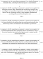
FIG. 1 , themethanol injection system 100 includes an injection structure 1 and acontrol apparatus 3, the injection structure 1 includes afirst fuel injector 11 and asecond fuel injector 12, thefirst fuel injector 11 is provided in the cylinder of themethanol engine 9, thesecond fuel injector 12 is provided at the intake pipeline of themethanol engine 9, and thecontrol apparatus 3 is electrically connected to thefirst fuel injector 11 and thesecond fuel injector 12. - In the technical solution of the present application, the
first fuel injector 11 is provided so as to directly inject methanol fuel into the cylinder of themethanol engine 9, and thesecond fuel injector 12 is provided so as to inject methanol fuel into the intake pipeline. Meanwhile, thecontrol apparatus 3 is provided to control the injection amount of thefirst fuel injector 11 and thesecond fuel injector 12. Compared with one fuel injector, two fuel injectors can share the injection amount, and can reduce the injection amount of thefirst fuel injector 11 or thesecond fuel injector 12, which is conducive to reducing the probability of wall wetting and the energy required for methanol vaporization, and can significantly improve the atomization effect of methanol, thereby helping to improve the cold start performance of themethanol engine 9. - The
first fuel injector 11 may be provided at the top wall or sidewall of the cylinder of themethanol engine 9 so as to directly inject methanol into the cylinder of themethanol engine 9, i.e., direct injection into the cylinder. The intake pipeline includes the intake manifold and the cylinder cover intake pipeline of themethanol engine 9. Thesecond fuel injector 12 may be an intake duct provided at the intake manifold or the cylinder cover of themethanol engine 9 so as to inject methanol into the intake pipeline, i.e., the gas path injection. - It should be noted that, under different loads, the injection amounts of the
first fuel injector 11 and thesecond fuel injector 12 are different so that themethanol engine 9 can match different output powers. Therefore, the present application can realize multiple injection modes through thecontrol apparatus 3, so that themethanol engine 9 can better adapt to different loads. Further, the target power of themethanol engine 9 includes a first output power, a second output power and a third output power which increase in sequence. When themethanol engine 9 needs to operate at the first output power, thecontrol apparatus 3 controls thefirst fuel injector 11 to inject methanol so that themethanol engine 9 can operate at a low load. When themethanol engine 9 needs to operate at the second output power, thecontrol apparatus 3 controls thesecond fuel injector 12 and thefirst fuel injector 11 to inject methanol at a first injection ratio so that themethanol engine 9 can operate at a medium load. When themethanol engine 9 needs to operate at the third output power, thecontrol apparatus 3 controls thefirst fuel injector 11 and thesecond fuel injector 12 to inject methanol at a second injection ratio so that themethanol engine 9 can operate at a high load. The first injection ratio is different from the second injection ratio. Specifically, the injection ratio can be adjusted as needed. - Please refer to
FIG. 4 , thecontrol apparatus 3 may include: aprocessor 1001, such as a CPU, acommunication bus 1002, auser interface 1003, anetwork interface 1004, and amemory 1005. Thecommunication bus 1002 is configured to realize the connection and communication between these components. Theuser interface 1003 may include a display screen, an input unit such as a keyboard, and theuser interface 1003 may also include a standard wired interface and a wireless interface. Thenetwork interface 1004 may include a standard wired interface and a wireless interface (such as a WI-FI interface). Thememory 1005 may be a high-speed RAM memory, or a non-volatile memory, such as a disk memory. Thememory 1005 may also be a storage apparatus independent of theaforementioned processor 1001. - In an embodiment, the fuel pressure of the
first fuel injector 11 is P1, and P1 is not less than 100bar, so that the high fuel pressure is helpful to improve the atomization effect of the first fuel injector, reduce the risk of wall wetting, and improve the cold start performance of themethanol engine 9. Theoretically, the higher the pressure is, the better the atomization effect of thefirst fuel injector 11 will be, but the technical difficulty and cost are also higher. Therefore, in this embodiment, P1 is not less than 200bar and not greater than 500bar, which can not only improve the atomization effect of thefirst fuel injector 11, facilitate the full mixing of the gas, avoid wall wetting and improve the cold start performance, but also reduce the cost of themethanol injection system 100. It can be understood that the fuel pressure P1 of thefirst fuel injector 11 can be 250bar, 300bar, 350bar or 400bar, and of course can be any value in the above range, which is not limited in the present application. Specifically, P1 is not less than 200bar and not greater than 350bar. - In an embodiment, the fuel pressure of the
second fuel injector 12 is P2, and P2 is less than 100bar. Since thesecond fuel injector 12 is outside the cylinder of themethanol engine 9, it is not easy to cause the wall wetting problem. Therefore, thesecond fuel injector 12 adopts a lower fuel pressure to reduce the cost of themethanol injection system 100. It can be understood that the fuel pressure P2 of thesecond fuel injector 12 can be 15bar, 35bar, 55bar or 80bar, and of course it can also be any value in the above range, which is not limited in the present application. Specifically, P2 is not greater than 20bar, so as to adapt to the existing methanol fuel supply system, make use of the components in the existing methanol fuel supply system, thereby helping to reduce the cost of themethanol injection system 100. - In an embodiment, the fuel pressure of the first fuel injector and the fuel pressure of the second fuel injector are P1 and P2 respectively, and P1 is not less than 100bar, and P2 is not less than 100bar, so that the
first fuel injector 11 and thesecond fuel injector 12 both use high-pressure injection to ensure the atomization effect of methanol, thereby facilitating the cold start performance of themethanol engine 9. It should be noted that the fuel pressure of thefirst fuel injector 11 and the fuel pressure of thesecond fuel injector 12 may be the same or different, as long as the fuel pressure of thefirst fuel injector 11 and the fuel pressure of thesecond fuel injector 12 are not less than 100bar, which is not limited in the present application. - Theoretically, the higher the pressure is, the better the atomization effect will be, but the technical difficulty and cost are also higher. Therefore, in this embodiment, P is not less than 200bar and not greater than 500bar, which can not only improve the atomization effect of the
first fuel injector 11 and the second fuel injector, facilitate the full mixing of the gas, avoid wall wetting and improve the cold start performance, but also reduce the cost of themethanol injection system 100. It can be understood that the fuel pressure P of thefirst fuel injector 11 and thesecond fuel injector 12 can be 250bar, 300bar, 350bar or 400bar, and of course it can be any value in the above range, which is not limited in the present application. Specifically, P1 is not less than 200bar and not greater than 350bar. - In some embodiments of the present application, the fuel pressure of the first fuel injector and the fuel pressure of the second fuel injector are P1 and P2 respectively. P1 is not less than 100bar, P2 is less than 100bar. Since the
second fuel injector 12 is outside the cylinder of themethanol engine 9 and is not prone to wall wetting, thesecond fuel injector 12 uses a lower fuel pressure to reduce the cost of themethanol injection system 100. Thefirst fuel injector 11 is inside the cylinder of themethanol engine 9 and is prone to wall wetting. Therefore, thefirst fuel injector 11 uses a higher fuel pressure to improve the atomization effect of thefirst fuel injector 11 and reduce the probability of wall wetting. - In an embodiment, P1 is not less than 200bar and not greater than 500bar, which not only can improve the atomization effect of the
first fuel injector 11, facilitate the full mixing of the gas, avoid wall wetting and improve the high cold start performance, but can also reduce the cost of themethanol injection system 100. It can be understood that the fuel pressure P1 of thefirst fuel injector 11 can be 250bar, 300bar, 350bar or 400bar, and of course it can also be any value in the above range, which is not limited in the present application. Specifically, P1 is not less than 200bar and not greater than 350bar. In addition, P2 is not greater than 20bar, so as to adapt to the existing methanol fuel supply system and make use of the components in the existing methanol fuel supply system, thereby helping to reduce the cost of themethanol injection system 100. It can be understood that the fuel pressure P2 of thesecond fuel injector 12 can be 15bar, 35bar, 55bar or 80bar, and of course it can also be any value in the above range, which is not limited in the present application. - In order to replenish methanol to the
first fuel injector 11 and thesecond fuel injector 12, in this embodiment, themethanol injection system 100 includes amethanol tank 8 and a fuel supply pipeline 2. The fuel supply pipeline 2 includes a fuel supply main pipe 21 and a first fuel supply branch pipe 22 and a second fuelsupply branch pipe 23 communicated with the fuel supply main pipe. The fuel supply main pipe 21 is communicated with themethanol tank 8, the tail end of the first fuel supply branch pipe 22 is communicated with thefirst fuel injector 11, and the tail end of the second fuelsupply branch pipe 23 is communicated with thesecond fuel injector 12. In this way, by setting the fuel supply main pipe 21, methanol fuel can be supplied to the second fuelsupply branch pipe 23 and the first fuel supply branch pipe 22 at the same time; and by setting the second fuelsupply branch pipe 23 and the first fuel supply branch pipe 22, methanol fuel can be supplied to thesecond fuel injector 12 and thefirst fuel injector 11 respectively. - In order to replenish methanol to the
first fuel injector 11, in this embodiment, themethanol injection system 100 also includes a high-pressure fuel pump 5 provided at the first fuel supply branch pipe 22, and the high-pressure fuel pump 5 is electrically connected to thecontrol apparatus 3. In this way, the high-pressure fuel pump 5 is provided to drive the methanol in the first fuel supply branch pipe 22 to flow to thefirst fuel injector 11. The high-pressure fuel pump 5 is electrically connected to thecontrol apparatus 3, so that when thefirst fuel injector 11 injects methanol, thecontrol apparatus 3 can control the high-pressure fuel pump 5 to synchronously replenish methanol to thefirst fuel injector 11. - In order to replenish methanol to the
second fuel injector 12, in this embodiment, themethanol injection system 100 further includes a low-pressure fuel pump 4 provided at the fuel supply main pipe 21 or the second fuelsupply branch pipe 23, and the low-pressure fuel pump 4 is electrically connected to thecontrol apparatus 3. In this way, the low-pressure fuel pump 4 is provided to drive the methanol in the second fuelsupply branch pipe 23 to flow to thesecond fuel injector 12. The low-pressure fuel pump 4 is electrically connected to thecontrol apparatus 3, so that when thesecond fuel injector 12 injects methanol, thecontrol apparatus 3 can control the low-pressure fuel pump 4 to synchronously replenish methanol to thesecond fuel injector 12. Furthermore, since the inlet pressure of the high-pressure fuel pump 5 is relatively high, it is difficult for methanol fuel to flow from themethanol tank 8 into the high-pressure fuel pump 5. Therefore, in this embodiment, the low-pressure fuel pump 4 is provided at the fuel supply main pipe 21, so that the low-pressure fuel pump 4 can both replenish methanol to thesecond fuel injector 12 and increase the fuel pressure of the fuel supply main pipe 21, so that methanol fuel can flow smoothly into the high-pressure fuel pump 5. - In an embodiment, please refer to
FIG. 2 , the fuel pressure of thefirst fuel injector 11 and the fuel pressure of thesecond fuel injector 12 are P1 and P2 respectively. P1 is not less than 100bar, and P2 is not less than 100bar. Themethanol injection system 100 further includes a high-pressure fuel pump 5 provided at the fuel supply main pipe 21, and the high-pressure fuel pump 5 is electrically connected to thecontrol apparatus 3, so that the high-pressure fuel pump 5 is provided to drive the methanol in the first fuel supply branch pipe 22 and the second fuelsupply branch pipe 23 to flow to thefirst fuel injector 11 and thesecond fuel injector 12 respectively. The high-pressure fuel pump 5 is electrically connected to thecontrol apparatus 3, so that when the first fuel supply branch pipe 22 and the second fuelsupply branch pipe 23 are filled, thecontrol apparatus 3 can control the high-pressure fuel pump 5 to synchronously replenish methanol to the first fuel supply branch pipe 22 and the second fuelsupply branch pipe 23. - Since the inlet pressure of the high-
pressure fuel pump 5 is relatively high, it is difficult for methanol fuel to flow from themethanol tank 8 into the high-pressure fuel pump 5. Therefore, in this embodiment, the methanol injection system further includes a low-pressure fuel pump 4 provided at the fuel supply main pipe 21. The low-pressure fuel pump 4 is electrically connected to the control apparatus. Thus, by providing the low-pressure fuel pump 4, the fuel pressure of the fuel supply main pipe 21 is increased, so that methanol fuel can flow smoothly into the high-pressure fuel pump 5, thereby facilitating the continuous supply of methanol to the injection structure 1. - Please refer to
FIG. 3 , the fuel pressure of thefirst fuel injector 11 and the fuel pressure of thesecond fuel injector 12 are P1 and P2 respectively. P1 is not less than 100bar, and P2 is less than 100bar. The methanol injection system further includes a high-pressure fuel pump provided at the first fuel supply branch pipe 22, and the high-pressure fuel pump is electrically connected to the control apparatus, so that the high-pressure fuel pump 5 is provided to drive the methanol in the first fuel supply branch pipe 22 to flow to thefirst fuel injector 11. The high-pressure fuel pump 5 is electrically connected to thecontrol apparatus 3, so that when thefirst fuel injector 11 injects methanol, thecontrol apparatus 3 can control the high-pressure fuel pump 5 to synchronously replenish methanol to thefirst fuel injector 11. - In an embodiment, the
methanol injection system 100 further includes a low-pressure fuel pump 4 provided at the fuel supply main pipe 21 or the second fuelsupply branch pipe 23, and the low-pressure fuel pump 4 is electrically connected to thecontrol apparatus 3. Thus, by providing the low-pressure fuel pump 4, the methanol in the second fuelsupply branch pipe 23 is driven to flow to thesecond fuel injector 12. The low-pressure fuel pump 4 is electrically connected to thecontrol apparatus 3, so that when thesecond fuel injector 12 injects methanol, thecontrol apparatus 3 can control the low-pressure fuel pump 4 to synchronously replenish methanol to thesecond fuel injector 12. Further, the low-pressure fuel pump 4 is provided at the fuel supply main pipe 21, so that the low-pressure fuel pump 4 can replenish methanol to thesecond fuel injector 12 and increase the fuel pressure of the fuel supply main pipe 21, and the methanol fuel can flow smoothly into the high-pressure fuel pump 5. - The number of the
first fuel injector 11 may be one or more, which is not limited in the present application. In this embodiment, a plurality offirst fuel injectors 11 correspond to the plurality of cylinders of themethanol engine 9, so as to directly inject methanol into the corresponding cylinder, so that the first fuel injector matches the cylinder of themethanol engine 9, and the injection amount can be controlled according to the combustion state of each cylinder, which can not only reduce fuel consumption but also improve power. - In an embodiment, a plurality of the
second fuel injectors 12 are respectively provided corresponding to the plurality of cylinders of themethanol engine 9, so as to inject methanol into the intake duct of the corresponding cylinder, so that thesecond fuel injector 12 matches the cylinder of themethanol engine 9, and the injection amount of each cylinder is accurately controlled. - In order to facilitate the distribution of methanol to the plurality of
first fuel injectors 11, in this embodiment, themethanol injection system 100 further includes afuel rail 6 provided at the first fuel supply branch pipe 22 to be communicated with the plurality offirst fuel injectors 11. Thus, thefuel rail 6 is provided to store methanol, which can supply methanol to the plurality offirst fuel injectors 11, and restrain the pressure fluctuations generated by the high-pressure fuel pump 5 and thefirst fuel injector 11, which is beneficial for themethanol injection system 100 to maintain the stable pressure. - In order to facilitate the distribution of methanol to the plurality of
second fuel injectors 12, in this embodiment, thefuel rail 6 is provided at the second fuelsupply branch pipe 23 to be communicated with the plurality ofsecond fuel injectors 12. Thus, thefuel rail 6 is provided to store methanol, which can supply methanol to the plurality ofsecond fuel injectors 12, and restrain the pressure fluctuations generated by the high-pressure fuel pump 5 and thesecond fuel injector 12, which is beneficial for themethanol injection system 100 to maintain the stable pressure. - In an embodiment, the
methanol injection system 100 further includes arail pressure sensor 7 provided at thefuel rail 6, and therail pressure sensor 7 is electrically connected to thecontrol apparatus 3. Thus, therail pressure sensor 7 is provided to detect the pressure in thefuel rail 6. Meanwhile, therail pressure sensor 7 is electrically connected to thecontrol apparatus 3, so that thecontrol apparatus 3 can adjust the output power of the low-pressure fuel pump 4 and the high-pressure fuel pump 5 according to the pressure detected by therail pressure sensor 7, so that the pressure of themethanol injection system 100 is kept stable. - In an embodiment, the
methanol injection system 100 includes amethanol engine 9, and themethanol engine 9 includes a cylinder. The cylinder is provided with anintake duct 91, and the injection port of the low-pressure fuel injector is provided at theintake duct 91. Thus, thefirst fuel injector 11 is provided at theintake duct 91, so as to control the injection amount according to the combustion state of each cylinder. Of course, in other embodiments, thefirst fuel injector 11 may also be a manifold provided at the intake manifold, which is not limited in the present application. It should be understood that the intake pipeline includes the intake manifold communicated with the cylinder and theintake duct 91 in the cylinder. Whether provided at the intake manifold or the intake duct, thefirst fuel injector 11 can inject methanol into the intake pipeline, that is, the gas path injection. - There are many settings for the
first fuel injector 11 in the cylinder of themethanol engine 9. Specifically, in this embodiment, the injection port of thefirst fuel injector 11 is provided at the top or side of the cylinder of themethanol engine 9, so as to directly inject methanol into the cylinder of themethanol engine 9, that is, the direct injection into the cylinder. It should be understood that thefirst fuel injector 11 is specifically provided at the top or side of the cylinder, which can be selected according to the overall layout of themethanol engine 9, and is not limited in the present application. - In some embodiments, the
methanol injection system 100 further includes amethanol engine 9, and themethanol engine 9 includes a cylinder. The cylinder is provided with anintake duct 91, the injection port of thesecond fuel injector 12 is provided at theintake duct 91, and the intake pipeline includes theintake duct 91. In this way, thesecond fuel injector 12 is provided at theintake duct 91, so as to control the injection amount according to the combustion state of each cylinder. Of course, in other embodiments, thesecond fuel injector 12 can also be a manifold provided at the intake manifold, which is not limited in the present application. It can be understood that the intake pipeline includes the intake manifold communicated with the cylinder and theintake duct 91 in the cylinder. Whether provided at the intake manifold or the intake duct, thesecond fuel injector 12 can inject methanol into the intake pipeline, that is, the gas path injection. - In addition, to achieve the above purpose, the present application also provides a vehicle, including the
methanol injection system 100. It should be noted that the structure of themethanol injection system 100 in the vehicle can refer to the embodiment of themethanol injection system 100, which will not be described here. Since themethanol injection system 100 is adopted in the vehicle provided in the present application, the embodiment of the vehicle provided in the present application includes all technical solutions of all embodiments of themethanol injection system 100, and the technical effects achieved are also exactly the same, which will not be described here. - Those skilled in the art can understand that the structure shown in
FIG. 2 does not constitute a limitation on thecontrol apparatus 3, and may include more or less components than shown in the figure, or combine certain components, or arrange components differently. - As shown in
FIG. 4 , thememory 1005, as a storage medium, may include an operating system, a network communication module, a user interface module, and a control program of themethanol injection system 100. - In the
control apparatus 3 shown inFIG. 4 , thenetwork interface 1004 is mainly configured for data communication with the network server; theuser interface 1003 is mainly configured for data interaction with the user; theprocessor 1001 and thememory 1005 in thecontrol apparatus 3 of the present application can be provided in thecontrol apparatus 3, and thecontrol apparatus 3 calls the control program of themethanol injection system 100 stored in thememory 1005 through theprocessor 1001, and executes the control method of themethanol injection system 100 provided in the embodiment of the present application. - Based on the above hardware structure, the present application provides a methanol injection control method, which controls the injection amount of the
first fuel injector 11 and thesecond fuel injector 12 so that the two fuel injectors can share the injection amount, and can reduce the injection amount of thefirst fuel injector 11 or thesecond fuel injector 12, which can reduce the probability of wall wetting, reduce the energy required for vaporization, and significantly improve the atomization effect, thereby helping to improve the cold start performance of themethanol engine 9. - Please refer to
FIG. 5 , which is a flowchart of the methanol injection control method according to the first embodiment of the present application. - The
methanol injection system 100 includes an injection structure 1 and acontrol apparatus 3, and the injection structure 1 includes afirst fuel injector 11 and asecond fuel injector 12. Thefirst fuel injector 11 is provided in the cylinder of themethanol engine 9, and thesecond fuel injector 12 is provided at the intake pipeline of themethanol engine 9. Thecontrol apparatus 3 is electrically connected to the injection structure 1, and the methanol injection control method is applied to thecontrol apparatus 3, including the following steps:
S10: obtaining the required power parameter of themethanol engine 9. - It should be noted that the required power parameter of the
methanol engine 9 refers to the ratio of the power which the engine needs to output to the total power output by the engine. The required power parameter of themethanol engine 9 will also be different under different loads. - S20: determining an injection strategy according to the required power parameter, and controlling the injection of the
first fuel injector 11 and/or thesecond fuel injector 12 according to the injection strategy. - In this embodiment, the required power parameter of the
methanol engine 9 is obtained, so as to determine the injection strategy of the injection structure 1 according to the required power parameter. Thus, the required power parameter is used to determine the injection ratio of thefirst fuel injector 11 and thesecond fuel injector 12 under different powers, so that the injection amount of thefirst fuel injector 11 and thesecond fuel injector 12 can be adapted to the load of themethanol engine 9, which can ensure the output power of themethanol engine 9, reduce the probability of wall wetting of themethanol engine 9, reduce the energy required for methanol vaporization, and effectively improve the atomization effect of methanol, thereby helping to improve the cold start performance of themethanol engine 9. - The required power parameter of the
methanol engine 9 is different, and the total injection amount of the injection structure 1 is also different. The larger the required power parameter of themethanol engine 9 is, the greater the total injection amount of the injection structure 1 will be. Further, the injection ratio of thefirst fuel injector 11 and thesecond fuel injector 12 also needs to be adjusted accordingly. - In an embodiment, the
first fuel injector 11 is provided at various positions. Specifically, in an embodiment, thefirst fuel injector 11 is provided at the top of the cylinder. - Please refer to
FIG. 7 , the step S20 includes: - S21: in response to that the required power parameter is less than the first preset threshold value, controlling the
first fuel injector 11 to inject methanol; and - S22: in response to that the required power parameter is greater than or equal to the first preset threshold value, determining the first mixed injection ratio according to the required power parameter, and controlling the
first fuel injector 11 and thesecond fuel injector 12 to inject methanol simultaneously according to the first mixed injection ratio. - In this embodiment, when the required power parameter is less than the first preset threshold value, it means that the load of the
methanol engine 9 is small and the power to be provided is not high. At this time, the injection amount of the injection structure 1 is the smallest, and thefirst fuel injector 11 can inject methanol. When the required power parameter is greater than or equal to the first preset threshold value, it means that the load of themethanol engine 9 is large and the power to be provided is larger. At this time, the injection amount of a single fuel injector cannot meet the requirements, and thefirst fuel injector 11 and thesecond fuel injector 12 need to inject methanol at the same time to ensure that the injection amount of the injection structure 1 matches the load of themethanol engine 9. - It should be noted that when the
first fuel injector 11 is provided at the top of the cylinder, a higher pressure can be provided, which is conducive to improving the combustion efficiency of methanol, and avoids the wall wetting problem. At this time, in the first mixed injection ratio, the injection amount of thefirst fuel injector 11 is greater than the injection amount of thesecond fuel injector 12, that is, the direct injection in the cylinder is mainly used. Further, the first preset threshold value may be a fixed value or a value range, etc., which is not limited in the present application. In reality, taking the first preset threshold value as 25% for an example, when the required power parameter is 15%, it means that the load of themethanol engine 9 is small, the power required to be output by the engine is not large, and the amount of methanol required to be injected by the injection structure 1 is the smallest. At this time, only thefirst fuel injector 11 needs to inject methanol. When the required power parameter is 35%, it means that the load of themethanol engine 9 is large, and the power required to be output by the engine is high, that is, the amount of methanol required to be injected by the injection structure 1 is large. At this time, thefirst fuel injector 11 and thesecond fuel injector 12 need to inject methanol at the same time to ensure that the injection amount of the injection structure 1 can match the load of themethanol engine 9, and the injection amount of thefirst fuel injector 11 is greater than the injection amount of thesecond fuel injector 12. - In an embodiment, please refer to
FIG. 9 , step S22 includes: - S221: in response to that the required power parameter is greater than or equal to the first preset threshold value and less than the second preset threshold value, determining the first mixed injection ratio as the first injection ratio; and
- S222: in response to that the required power parameter is greater than or equal to the second preset threshold value, determining the first mixed injection ratio as the second injection ratio, and the first injection ratio is greater than the second injection ratio.
- In this embodiment, when the required power parameter is greater than or equal to the first preset threshold value and less than the second preset threshold value, it means that the load of the
methanol engine 9 is medium load, and the injection amount of the injection structure 1 is medium. At this time, thefirst fuel injector 11 and thesecond fuel injector 12 inject methanol according to the first injection ratio, mainly with thefirst fuel injector 11. When the required power parameter is greater than or equal to the second preset threshold value, it means that the load of themethanol engine 9 is high load, and the injection amount of the injection structure 1 is the largest. At this time, if thefirst fuel injector 11 and thesecond fuel injector 12 still inject methanol according to the first injection ratio, the injection amount of thefirst fuel injector 11 will be too large, which may easily cause the risk of wall wetting. Therefore, thefirst fuel injector 11 and thesecond fuel injector 12 need to inject methanol according to the second injection ratio to avoid excessive injection amount of a single fuel injector. In this way, the injection ratio of the first injector and the second injector is determined by the required power parameter, so that the injection ratio and the injection amount of the injection structure 1 can be adapted to the load of themethanol engine 9. - It should be noted that the first injection ratio and the second injection ratio both refer to the ratio of the injection amount of the
first fuel injector 11 to the injection amount of thesecond fuel injector 12. Furthermore, the second preset threshold value can be a fixed value or a value range, etc., which is not limited in the present application. In reality, taking the first preset threshold value as 25% and the second preset threshold value as 50% for example, when the required power parameter is 40%, it means that the load of themethanol engine 9 is medium, and the injection amount of the injection structure 1 is medium. At this time, thefirst fuel injector 11 and thesecond fuel injector 12 inject methanol according to the first injection ratio, mainly with thefirst fuel injector 11. When the required power parameter is 60%, it means that the load of themethanol engine 9 is high, and the injection amount of the injection structure 1 is the largest. At this time, thefirst fuel injector 11 and thesecond fuel injector 12 inject methanol according to the second injection ratio, so that thesecond fuel injector 12 can share the injection amount of the injection structure 1, which can match the injection amount of the injection structure 1 with the load of themethanol engine 9, and avoid excessive injection amount of a single fuel injector, thereby helping to avoid the wall wetting problem of themethanol engine 9. - In an embodiment, the first injection ratio and the second injection ratio are not limited and can be adjusted as needed. Specifically, in an embodiment, in the first injection ratio: the injection amount of the
first fuel injector 11 accounts for 65% to 80% of the total injection amount, and the injection amount of thesecond fuel injector 12 accounts for 20% to 35% of the total injection amount. At this time, themethanol engine 9 is in a medium load, and the injection amount of the injection structure 1 is medium. Since thefirst fuel injector 11 is provided at the top of the cylinder, the combustion efficiency is high and the wall wetting problem is not easy to occur, thefirst fuel injector 11 is mainly used to inject methanol, so as to improve the combustion efficiency of themethanol engine 9. In another embodiment, in the second injection ratio: the injection amount of thefirst fuel injector 11 accounts for 50% to 60% of the total injection amount, and the injection amount of thesecond fuel injector 12 accounts for 40% to 50% of the total injection amount. At this time, themethanol engine 9 is at a high load, and the injection amount of the injection structure 1 is large. In order to avoid excessive injection amount of a single injector, the injection amount of thesecond fuel injector 12 needs to be increased to avoid the wall wetting problem in themethanol engine 9. - In an embodiment, the
first fuel injector 11 is provided at the sidewall of the cylinder. - Please refer to
FIG. 8 , step S20 includes: - S23: in response to that the required power parameter is less than the first preset threshold value, controlling the
first fuel injector 11 to inject methanol; and - S24: in response to that the required power parameter is greater than or equal to the first preset threshold value, determining the second mixed injection ratio according to the required power parameter, and controlling the
first fuel injector 11 and thesecond fuel injector 12 to inject methanol simultaneously according to the second mixed injection ratio. - In this embodiment, when the required power parameter is less than the first preset threshold value, it means that the load of the
methanol engine 9 is small and the power to be provided is not high. At this time, the injection amount of the injection structure 1 is the smallest, and thefirst fuel injector 11 can inject methanol. When the required power parameter is greater than or equal to the first preset threshold value, it means that the load of themethanol engine 9 is large and the power to be provided is large. At this time, the injection amount of a single fuel injector is insufficient to meet the requirement, and thefirst fuel injector 11 and thesecond fuel injector 12 need to inject methanol at the same time to ensure that the injection amount of the injection structure 1 matches the load of themethanol engine 9. - It should be noted that when the
first fuel injector 11 is provided at the sidewall of the cylinder, the spray hole of thefirst fuel injector 11 is facing the cylinder barrel and is relatively top-mounted, which is more likely to cause wall wetting problems. At this time, in the second mixed injection ratio, the injection amount of thefirst fuel injector 11 is less than the injection amount of thesecond fuel injector 12, that is, the gas path injection is mainly used. Further, the first preset threshold value may be a fixed value or a value range, etc., which is not limited in the present application. In reality, taking the first preset threshold value as 25% for an example, when the required power parameter is 15%, it means that the load of themethanol engine 9 is small, the power required to be output by the engine is not large, and the amount of methanol required to be injected by the injection structure 1 is the smallest. At this time, only thefirst fuel injector 11 is required to inject methanol. When the required power parameter is 35%, it means that the load of themethanol engine 9 is large, and the power required to be output by the engine is high, that is, the amount of methanol required to be injected by the injection structure 1 is large. At this time, thefirst fuel injector 11 and thesecond fuel injector 12 are required to inject methanol at the same time to ensure that the injection amount of the injection structure 1 can match the load of themethanol engine 9, and the injection amount of thesecond fuel injector 12 is greater than the injection amount of thefirst fuel injector 11. - In an embodiment, please refer to
FIG. 10 , step S24 includes: - S241: in response to that the required power parameter is greater than or equal to the first preset threshold value and less than the second preset threshold value, determining the second mixed injection ratio as the third injection ratio;
- S242: in response to that the required power parameter is greater than or equal to the second preset threshold value, determining the second mixed injection ratio as the fourth injection ratio, and the third injection ratio is less than the fourth injection ratio.
- In this embodiment, when the required power parameter is greater than or equal to the first preset threshold value and less than the second preset threshold value, it means that the load of the
methanol engine 9 is medium load, and the injection amount of the injection structure 1 is medium. At this time, thefirst fuel injector 11 and thesecond fuel injector 12 inject methanol according to the third injection ratio, mainly with thesecond fuel injector 12. When the required power parameter is greater than or equal to the second preset threshold value, it means that the load of themethanol engine 9 is high load, and the injection amount of the injection structure 1 is the largest. At this time, if thefirst fuel injector 11 and thesecond fuel injector 12 still inject methanol according to the third injection ratio, the injection amount of thesecond fuel injector 12 will be too large, which may easily cause the wall wetting. Therefore, thefirst fuel injector 11 and thesecond fuel injector 12 need to be injected methanol according to the fourth injection ratio to avoid excessive injection amount of a single fuel injector. In this way, the injection ratio of the first injector and the second injector is determined by the required power parameter, so that the injection ratio and the injection amount of the injection structure 1 can be adapted to the load of themethanol engine 9. - It should be noted that the third injection ratio and the fourth injection ratio both refer to the ratio of the injection amount of the
first fuel injector 11 to the injection amount of thesecond fuel injector 12. Furthermore, the second preset threshold value can be a fixed value or a value range, etc., which is not limited in the present application. In reality, taking the first preset threshold value as 25% and the second preset threshold value as 50% for an example. When the required power parameter is 40%, it means that the load of themethanol engine 9 is medium, and the injection amount of the injection structure 1 is medium. At this time, thefirst fuel injector 11 and thesecond fuel injector 12 inject methanol according to the third injection ratio, mainly with thesecond fuel injector 12. When the required power parameter is 60%, it means that the load of themethanol engine 9 is high and the injection amount of the injection structure 1 is the largest. At this time, thefirst fuel injector 11 and thesecond fuel injector 12 inject methanol according to the fourth injection ratio, so that thefirst fuel injector 11 can share the injection amount of the injection structure 1, which can match the injection amount of the injection structure 1 with the load of the methanol engine, and avoid excessive injection amount of a single fuel injector, thereby helping to avoid the wall wetting problem of the methanol engine. - In an embodiment, the third injection ratio and the fourth injection ratio are not limited and can be adjusted as needed. Specifically, in an embodiment, in the third injection ratio: the injection amount of the
first fuel injector 11 accounts for 20% to 35% of the total injection amount, and the injection amount of thesecond fuel injector 12 accounts for 65% to 80% of the total injection amount. At this time, themethanol engine 9 is in medium load, and the injection amount of the injection structure 1 is medium. Since thefirst fuel injector 11 is provided at the sidewall of the cylinder, the wall wetting problem is likely to occur. Therefore, thesecond fuel injector 12 is mainly used to inject methanol to avoid the wall wetting problem of themethanol engine 9. In another embodiment, in the fourth injection ratio: the injection amount of thefirst fuel injector 11 accounts for 40% to 50% of the total injection amount, and the injection amount of thesecond fuel injector 12 accounts for 50% to 60% of the total injection amount. At this time, themethanol engine 9 is at a high load, and the injection amount of the injection structure 1 is large. In order to avoid excessive injection amount of a single injector, the injection amount of thefirst fuel injector 11 needs to be increased to share the injection amount of the injection structure 1, thereby helping to avoid the wall wetting problem of themethanol engine 9. - Please refer to
FIG. 6 , the methanol injection system further includes a methanol tank, a fuel supply pipeline and a power apparatus. The inlet of the fuel supply pipeline is communicated with the methanol tank, the outlet of the fuel supply pipeline is communicated with thefirst fuel injector 11 and thesecond fuel injector 12 respectively, and the power apparatus is provided at the fuel supply pipeline and electrically connected to the control apparatus. - The methanol injection control method further includes the following steps :
- S30: obtaining the first actual fuel pressure of the
first fuel injector 11 and the second actual fuel pressure of thesecond fuel injector 12; and - S40: determining a supply strategy according to the first actual fuel pressure and/or the second actual fuel pressure, and controlling the fuel supply of the power apparatus according to the supply strategy.
- In this embodiment, the first actual fuel pressure and the second actual fuel pressure are obtained to determine the methanol supply strategy of the
first fuel injector 11 and thesecond fuel injector 12. Thus, whether it is necessary to supply methanol to thefirst fuel injector 11 and thesecond fuel injector 12 is determined by the first actual fuel pressure and the second actual fuel pressure, so as to control the power apparatus to supply methanol to thefirst fuel injector 11 and thesecond fuel injector 12 in time. - In an embodiment, the fuel supply pipeline includes a fuel supply main pipe communicated with the methanol tank and a first fuel supply branch pipe and a second fuel supply branch pipe communicated with the fuel supply main pipe. A tail end of the first fuel supply branch pipe is communicated with the
first fuel injector 11, a tail end of the second fuel supply branch pipe is communicated with thesecond fuel injector 12, and the power apparatus is provided at the fuel supply main pipe. - Step S40 includes:
in response to that the first actual fuel pressure is less than the first preset fuel pressure, and/or the second actual fuel pressure is less than the first preset fuel pressure, the power apparatus works until the first actual fuel pressure and the second actual fuel pressure are not less than the first preset fuel pressure. - In this embodiment, when the first actual fuel pressure is less than the first preset fuel pressure, and/or the second actual fuel pressure is less than the first preset fuel pressure, it means that the
first fuel injector 11 and/or thesecond fuel injector 12 are injecting methanol, and thefirst fuel injector 11 and/or thesecond fuel injector 12 need to be replenished with methanol. At this time, the power apparatus is controlled to work so as to replenish methanol for thefirst fuel injector 11 and thesecond fuel injector 12. In this way, by obtaining the first actual fuel pressure and the second fuel pressure, the power apparatus is controlled to replenish methanol for thefirst fuel injector 11 and thesecond fuel injector 12 in time. - It should be noted that, in this embodiment, the fuel pressure of the
first fuel injector 11 and the fuel pressure of thesecond fuel injector 12 are the same. Further, the first preset fuel pressure can be a fixed value or a value range, etc., which is not limited in the present application. In reality, taking the first preset fuel pressure as 200bar for an example, if the first actual fuel pressure is less than 200bar, it means that thefirst fuel injector 11 is injecting methanol and needs to be replenished with methanol. At this time, the power apparatus works to replenish methanol for thefirst fuel injector 11. If the second actual fuel pressure is less than 200bar, it means that thesecond fuel injector 12 is injecting methanol and needs to be replenished with methanol. At this time, the power apparatus works to replenish methanol for thesecond fuel injector 12. That is, no matter whether the first actual fuel pressure decreases or the second actual fuel pressure decreases, the power apparatus needs to work. - In an embodiment, the fuel supply pipeline includes a fuel supply main pipe communicated with the methanol tank and a first fuel supply branch pipe and a second fuel supply branch pipe communicated with the fuel supply main pipe. A tail end of the first fuel supply branch pipe is communicated with the
first fuel injector 11, a tail end of the second fuel supply branch pipe is communicated with thesecond fuel injector 12, and the power apparatus includes a first fuel pump provided at the fuel supply main pipe and a second fuel pump provided at the first fuel supply branch pipe. - Please refer to
FIG. 11 , step S40 includes: - S42: in response to that the first actual fuel pressure is less than the second preset fuel pressure, making the first fuel pump and the second fuel pump work simultaneously until the first actual fuel pressure is not less than the second preset fuel pressure; and
- S43: in response to that the second actual fuel pressure is less than the third preset fuel pressure, making the first fuel pump work until the second actual fuel pressure is not less than the third preset fuel pressure, and the second preset fuel pressure is higher than the third preset fuel pressure.
- In this embodiment, when the first actual fuel pressure is less than the second preset fuel pressure, it means that the
first fuel injector 11 is injecting methanol and thefirst fuel injector 11 needs to be replenished with methanol. At this time, the first fuel pump and the second fuel pump work simultaneously to replenish methanol for thefirst fuel injector 11. When the second actual fuel pressure is less than the third preset fuel pressure, it means that thesecond fuel injector 12 is injecting methanol and thesecond fuel injector 12 needs to be replenished with methanol. At this time, only the first fuel pump needs to work. In this way, the first actual fuel pressure and the second actual fuel pressure are obtained, so as to control the power apparatus to replenish methanol for thefirst fuel injector 11 and thesecond fuel injector 12 in time. - It should be noted that in this embodiment, the fuel pressure of the
first fuel injector 11 and the fuel pressure of thesecond fuel injector 12 are different. Further, the second preset fuel pressure and the third preset fuel pressure can be a fixed value or a value range, etc., which is not limited in the present application. In reality, taking the second preset fuel pressure as 200bar and the third preset fuel pressure as 20 bar for an example, if the first actual fuel pressure is less than 200bar, it means that thefirst fuel injector 11 is injecting methanol and needs to be replenished with methanol. At this time, the first fuel pump and the second fuel pump work at the same time to replenish methanol to thefirst fuel injector 11. If the second actual fuel pressure is less than 20 bar, it means that thesecond fuel injector 12 is injecting methanol and needs to be replenished with methanol. At this time, the first fuel pump works to replenish methanol to thesecond fuel injector 12. - The above descriptions are only embodiments of the present application, and are not intended to limit the scope of the present application. Under the inventive concept of the present application, any equivalent structural transformations made by using the contents of the description and drawings of the present application, or direct/indirect applications in other related technical fields are included in the scope of the present application.
Claims (29)
- A methanol injection control method, applied to a methanol injection system, characterized in that, the methanol injection system comprises an injection structure and a control apparatus electrically connected to the injection structure, the injection structure comprises a first fuel injector provided in a cylinder of a methanol engine and a second fuel injector provided in an intake pipeline of the methanol engine, the methanol injection control method is applied to the control apparatus, and the methanol injection control method comprises:obtaining a required power parameter of the methanol engine; anddetermining an injection strategy according to the required power parameter, and controlling an injection of the first fuel injector and/or the second fuel injector according to the injection strategy.
- The methanol injection control method according to claim 1, wherein the first fuel injector is provided at a top of the cylinder; and
the determining the injection strategy according to the required power parameter, and controlling the injection of the first fuel injector and/or the second fuel injector according to the injection strategy comprises:in response to that the required power parameter is less than a first preset threshold value, controlling the first fuel injector to inject methanol; orin response to that the required power parameter is greater than or equal to a first preset threshold value, determining a first mixed injection ratio according to the required power parameter, and controlling the first fuel injector and the second fuel injector to inject methanol simultaneously according to the first mixed injection ratio. - The methanol injection control method according to claim 2, wherein the determining the first mixed injection ratio according to the required power parameter comprises:in response to that the required power parameter is greater than or equal to the first preset threshold value and less than a second preset threshold value, determining the first mixed injection ratio as a first injection ratio; orin response to that the required power parameter is greater than or equal to a second preset threshold value, determining the first mixed injection ratio as a second injection ratio, wherein the first injection ratio is greater than the second injection ratio.
- The methanol injection control method according to claim 3, whereinin the first injection ratio: an injection amount of the first fuel injector accounts for 65% to 80% of a total injection amount, and an injection amount of the second fuel injector accounts for 20% to 35% of the total injection amount; and/orin the second injection ratio: the injection amount of the first fuel injector accounts for 50% to 60% of the total injection amount, and the injection amount of the second fuel injector accounts for 40% to 50% of the total injection amount.
- The methanol injection control method according to claim 1, wherein the first fuel injector is provided at a sidewall of the cylinder; and
the determining the injection strategy according to the required power parameter, and controlling the injection of the first fuel injector and/or the second fuel injector according to the injection strategy comprises:in response to that the required power parameter is less than the first preset threshold value, controlling the first fuel injector to inject methanol; orin response to that the required power parameter is greater than or equal to the first preset threshold value, determining a second mixed injection ratio according to the required power parameter, and controlling the first fuel injector and the second fuel injector to inject methanol simultaneously according to the second mixed injection ratio. - The methanol injection control method according to claim 5, wherein the in response to that the required power parameter is greater than or equal to the first preset threshold value, determining the second mixed injection ratio according to the required power parameter, and controlling the first fuel injector and the second fuel injector to inject methanol simultaneously according to the second mixed injection ratio comprises:in response to that the required power parameter is greater than or equal to the first preset threshold value and less than the second preset threshold value, determining the second mixed injection ratio to be a third injection ratio; orin response to that the required power parameter is greater than or equal to the second preset threshold value, determining the second mixed injection ratio to be a fourth injection ratio, wherein the third injection ratio is less than the fourth injection ratio.
- The methanol injection control method according to claim 6, whereinin the third injection ratio: the injection amount of the first fuel injector accounts for 20% to 35% of the total injection amount, and the injection amount of the second fuel injector accounts for 65% to 80% of the total injection amount; and/orin the fourth injection ratio: the injection amount of the first fuel injector accounts for 40% to 50% of the total injection amount, and the injection amount of the second fuel injector accounts for 50% to 60% of the total injection amount.
- The methanol injection control method according to claim 1, wherein the methanol injection system further comprises a methanol tank, a fuel supply pipeline and a power apparatus, an inlet of the fuel supply pipeline is communicated with the methanol tank, an outlet of the fuel supply pipeline is respectively communicated with the first fuel injector and the second fuel injector, and the power apparatus is provided at the fuel supply pipeline and electrically connected to the control apparatus; and
the methanol injection control method further comprises:obtaining a first actual fuel pressure of the first fuel injector and a second actual fuel pressure of the second fuel injector; anddetermining a supply strategy according to the first actual fuel pressure and/or the second actual fuel pressure, and controlling the power apparatus to supply fuel according to the supply strategy. - The methanol injection control method according to claim 8, wherein the fuel supply pipeline comprises a fuel supply main pipe communicated with the methanol tank and a first fuel supply branch pipe and a second fuel supply branch pipe communicated with the fuel supply main pipe, a tail end of the first fuel supply branch pipe is communicated with the first fuel injector, and a tail end of the second fuel supply branch pipe is communicated with the second fuel injector, and the power apparatus is provided at the fuel supply main pipe; and
the determining the supply strategy according to the first actual fuel pressure and/or the second actual fuel pressure, and controlling the fuel supply of the power apparatus according to the supply strategy comprises:
in response to that the first actual fuel pressure is less than a first preset fuel pressure, and/or the second actual fuel pressure is less than the first preset fuel pressure, making the power apparatus work until the first actual fuel pressure and the second actual fuel pressure are not less than the first preset fuel pressure. - The methanol injection control method according to claim 8, wherein the fuel supply pipeline comprises a fuel supply main pipe communicated with the methanol tank and a first fuel supply branch pipe and a second fuel supply branch pipe communicated with the fuel supply main pipe, a tail end of the first fuel supply branch pipe is communicated with the first fuel injector, a tail end of the second fuel supply branch pipe is communicated with the second fuel injector, and the power apparatus comprises a first fuel pump provided at the fuel supply main pipe and a second fuel pump provided at the first fuel supply branch pipe; and
the determining the supply strategy according to the first actual fuel pressure and/or the second actual fuel pressure, and controlling the fuel supply of the power apparatus according to the supply strategy comprises:in response to that the first actual fuel pressure is less than a second preset fuel pressure, making the first fuel pump and the second fuel pump work simultaneously until the first actual fuel pressure is not less than the second preset fuel pressure; andin response to that the second actual fuel pressure is less than a third preset fuel pressure, making the first fuel pump work until the second actual fuel pressure is not less than the third preset fuel pressure, wherein the second preset fuel pressure is higher than the third preset fuel pressure. - A methanol injection system, characterized by comprising:an injection structure comprising a first fuel injector provided in a cylinder of a methanol engine and a second fuel injector provided in an intake pipeline of the methanol engine; anda control apparatus electrically connected to the first fuel injector and the second fuel injector, wherein the control apparatus comprises a memory, a processor, and a methanol injection control program stored in the memory and executable on the processor, and the methanol injection control program is configured to implement the methanol injection control method according to any one of claims 1 to 9.
- The methanol injection system according to claim 11, wherein a fuel pressure of the first fuel injector is P1, and P1 is not less than 100bar.
- The methanol injection system according to claim 12, wherein P1 is not less than 200bar and not greater than 500bar.
- The methanol injection system according to any one of claims 11 to 13, wherein a fuel pressure of the second fuel injector is P2, and P2 is less than 100 bar.
- The methanol injection system according to claim 11, wherein a fuel pressure of the first fuel injector is P1, a fuel pressure of the second fuel injector is P2, P1 is not less than 100 bar, and P2 is not less than 100 bar.
- The methanol injection system according to claim 15, wherein P1 is not less than 200bar and not greater than 500 bar, and P2 is not less than 200bar and not greater than 500 bar.
- The methanol injection system according to claim 11, wherein a fuel pressure of the first fuel injector is P1, a fuel pressure of the second fuel injector is P2, P1 is not less than 100 bar, and P2 is less than 100 bar.
- The methanol injection system according to claim 17, wherein P1 is not less than 200bar and not greater than 500 bar, and P2 is not greater than 20 bar.
- The methanol injection system according to claim 11, further comprising:a methanol tank; anda fuel supply pipeline comprising a fuel supply main pipe, and a first fuel supply branch pipe and a second fuel supply branch pipe communicated with the fuel supply main pipe, wherein the fuel supply main pipe is communicated with the methanol tank, a tail end of the first fuel supply branch pipe is communicated with the first fuel injector, and a tail end of the second fuel supply branch pipe is communicated with the second fuel injector.
- The methanol injection system according to claim 19, wherein:a fuel pressure of the first fuel injector is P1, a fuel pressure of the second fuel injector is P2, P1 is not less than 100bar, and P2 is not less than 100bar; andthe methanol injection system further comprises a high-pressure fuel pump provided at the fuel supply main pipe and electrically connected to the control apparatus.
- The methanol injection system according to claim 20, further comprising a low-pressure fuel pump provided at the fuel supply main pipe and electrically connected to the control apparatus.
- The methanol injection system according to claim 19, wherein:a fuel pressure of the first fuel injector is P1, a fuel pressure of the second fuel injector is P2, P1 is not less than 100bar, and P2 is less than 100bar; andthe methanol injection system further comprises a high-pressure fuel pump provided at the first fuel supply branch pipe and electrically connected to the control apparatus.
- The methanol injection system according to claim 22, further comprising a low-pressure fuel pump provided at the fuel supply main pipe and electrically connected to the control apparatus.
- The methanol injection system according to claim 19, further comprising a high-pressure fuel pump provided at the first fuel supply branch pipe and electrically connected to the control apparatus.
- The methanol injection system according to claim 11, wherein:a plurality of first fuel injectors correspond to a plurality of cylinders of the methanol engine respectively; and/ora plurality of second fuel injectors correspond to the plurality of cylinders of the methanol engine.
- The methanol injection system according to claim 25, further comprising a fuel rail, whereinthe fuel rail is provided at the first fuel supply branch pipe, and is communicated with the plurality of the first fuel injectors; and/orthe fuel rail is provided at the second fuel supply branch pipe, and is communicated with the plurality of the second fuel injectors.
- The methanol injection system according to claim 26, further comprising a rail pressure sensor provided at the fuel rail and electrically connected to the control apparatus.
- The methanol injection system according to claim 11, further comprising the methanol engine, whereinthe methanol engine comprises a cylinder;the cylinder is provided with an intake duct, and an injection port of the second fuel injector is provided at the intake duct; and/oran injection port of the first fuel injector is provided at a top or a side of the cylinder.
- A vehicle, characterized by comprising the methanol injection system according to any one of claims 11 to 28.
Applications Claiming Priority (4)
| Application Number | Priority Date | Filing Date | Title |
|---|---|---|---|
| CN202311391716.4A CN117449972A (en) | 2023-10-24 | 2023-10-24 | Methanol injection control method, methanol injection system and vehicle |
| CN202322868055.1U CN220909876U (en) | 2023-10-24 | 2023-10-24 | Methanol injection system and vehicle |
| CN202322873383.0U CN220909877U (en) | 2023-10-24 | 2023-10-24 | Methanol injection system and vehicle |
| PCT/CN2024/101701 WO2025086692A1 (en) | 2023-10-24 | 2024-06-26 | Methanol injection control method, methanol injection system, and vehicle |
Publications (1)
| Publication Number | Publication Date |
|---|---|
| EP4579072A1 true EP4579072A1 (en) | 2025-07-02 |
Family
ID=95514906
Family Applications (1)
| Application Number | Title | Priority Date | Filing Date |
|---|---|---|---|
| EP24826863.3A Pending EP4579072A1 (en) | 2023-10-24 | 2024-06-26 | Methanol injection control method, methanol injection system, and vehicle |
Country Status (2)
| Country | Link |
|---|---|
| EP (1) | EP4579072A1 (en) |
| WO (1) | WO2025086692A1 (en) |
Family Cites Families (6)
| Publication number | Priority date | Publication date | Assignee | Title |
|---|---|---|---|---|
| US10174704B2 (en) * | 2016-10-21 | 2019-01-08 | Ford Global Technologies, Llc | Systems and methods for controlling a fuel pump in start/stop and hybrid electric vehicles |
| CN106930875A (en) * | 2017-01-18 | 2017-07-07 | 浙江吉利控股集团有限公司 | Supply system of methanol engine fuel and startup control method |
| CN110242413B (en) * | 2019-07-12 | 2024-07-30 | 南京盖驰动力科技有限公司 | Gasoline low-pressure injection and methanol high-pressure injection system for engine air inlet pipe |
| CN114109635B (en) * | 2021-12-07 | 2023-03-21 | 浙江吉利控股集团有限公司 | Heavy methanol engine and control method of injection system of heavy methanol engine |
| CN219492439U (en) * | 2022-12-08 | 2023-08-08 | 山东中醇新科节能科技有限公司 | Dual-fuel supply structure of methanol engine |
| CN117449972A (en) * | 2023-10-24 | 2024-01-26 | 浙江吉利控股集团有限公司 | Methanol injection control method, methanol injection system and vehicle |
-
2024
- 2024-06-26 WO PCT/CN2024/101701 patent/WO2025086692A1/en active Pending
- 2024-06-26 EP EP24826863.3A patent/EP4579072A1/en active Pending
Also Published As
| Publication number | Publication date |
|---|---|
| WO2025086692A1 (en) | 2025-05-01 |
Similar Documents
| Publication | Publication Date | Title |
|---|---|---|
| US7464696B2 (en) | Fuel supply apparatus | |
| CN111594334B (en) | Method and system for fuel injection control of high pressure common rail engine | |
| CN110761920B (en) | Low-pressure gas supply system for small vessels | |
| US8905006B2 (en) | Diesel engine for a LPG-diesel mixture | |
| KR101361347B1 (en) | Common rail system for dme fuel | |
| CN117449972A (en) | Methanol injection control method, methanol injection system and vehicle | |
| US7121261B2 (en) | Fuel supply apparatus for internal combustion engine | |
| CN110242413B (en) | Gasoline low-pressure injection and methanol high-pressure injection system for engine air inlet pipe | |
| WO2022148425A1 (en) | Dual-injection system of gaseous fuel engine and control method therefor | |
| US20130333666A1 (en) | Internal combustion engine | |
| EP4579072A1 (en) | Methanol injection control method, methanol injection system, and vehicle | |
| CN117211999A (en) | An engine liquid ammonia fuel supply system and its control method | |
| EP2655856B1 (en) | Fuel injection system comprising a high-pressure fuel injection pump | |
| CN117514529A (en) | An ammonia-ether mixed fuel engine fuel supply system and efficient combustion method | |
| CN220909876U (en) | Methanol injection system and vehicle | |
| CN117605581A (en) | A mode control method for diesel and ammonia dual-fuel engines | |
| JP2009013818A (en) | Control device for internal combustion engine | |
| CN113187605B (en) | A high compression ratio engine and control method for burning hydrogen-dissolved fuel | |
| CN220909877U (en) | Methanol injection system and vehicle | |
| WO2021082638A1 (en) | Liquid dual-fuel medium-speed diesel engine system and speed governing control method therefor | |
| CN117552881A (en) | Efficient ignition control method suitable for liquid ammonia-diesel in-cylinder direct injection internal combustion engines | |
| CN211343148U (en) | Liquid dual-fuel medium-speed diesel engine system | |
| CN120159660B (en) | Intake duct liquid ammonia injection and exhaust gas recirculation heat recovery system and method | |
| JP2001115916A (en) | Diesel engine for dimethyl ether | |
| CN119616733B (en) | A multi-injection system integrating methanol and its cracked gas |
Legal Events
| Date | Code | Title | Description |
|---|---|---|---|
| STAA | Information on the status of an ep patent application or granted ep patent |
Free format text: STATUS: UNKNOWN |
|
| STAA | Information on the status of an ep patent application or granted ep patent |
Free format text: STATUS: THE INTERNATIONAL PUBLICATION HAS BEEN MADE |
|
| PUAI | Public reference made under article 153(3) epc to a published international application that has entered the european phase |
Free format text: ORIGINAL CODE: 0009012 |
|
| STAA | Information on the status of an ep patent application or granted ep patent |
Free format text: STATUS: REQUEST FOR EXAMINATION WAS MADE |
|
| 17P | Request for examination filed |
Effective date: 20241230 |
|
| AK | Designated contracting states |
Kind code of ref document: A1 Designated state(s): AL AT BE BG CH CY CZ DE DK EE ES FI FR GB GR HR HU IE IS IT LI LT LU LV MC ME MK MT NL NO PL PT RO RS SE SI SK SM TR |