EP4579060A1 - Integrally bladed disk and rotor blade portion for an integrally bladed disk - Google Patents
Integrally bladed disk and rotor blade portion for an integrally bladed disk Download PDFInfo
- Publication number
- EP4579060A1 EP4579060A1 EP24223244.5A EP24223244A EP4579060A1 EP 4579060 A1 EP4579060 A1 EP 4579060A1 EP 24223244 A EP24223244 A EP 24223244A EP 4579060 A1 EP4579060 A1 EP 4579060A1
- Authority
- EP
- European Patent Office
- Prior art keywords
- damper
- damper body
- airfoil
- tapered configuration
- Prior art date
- Legal status (The legal status is an assumption and is not a legal conclusion. Google has not performed a legal analysis and makes no representation as to the accuracy of the status listed.)
- Pending
Links
Images




Classifications
-
- F—MECHANICAL ENGINEERING; LIGHTING; HEATING; WEAPONS; BLASTING
- F01—MACHINES OR ENGINES IN GENERAL; ENGINE PLANTS IN GENERAL; STEAM ENGINES
- F01D—NON-POSITIVE DISPLACEMENT MACHINES OR ENGINES, e.g. STEAM TURBINES
- F01D5/00—Blades; Blade-carrying members; Heating, heat-insulating, cooling or antivibration means on the blades or the members
- F01D5/12—Blades
- F01D5/14—Form or construction
- F01D5/16—Form or construction for counteracting blade vibration
-
- F—MECHANICAL ENGINEERING; LIGHTING; HEATING; WEAPONS; BLASTING
- F01—MACHINES OR ENGINES IN GENERAL; ENGINE PLANTS IN GENERAL; STEAM ENGINES
- F01D—NON-POSITIVE DISPLACEMENT MACHINES OR ENGINES, e.g. STEAM TURBINES
- F01D5/00—Blades; Blade-carrying members; Heating, heat-insulating, cooling or antivibration means on the blades or the members
- F01D5/12—Blades
- F01D5/26—Antivibration means not restricted to blade form or construction or to blade-to-blade connections or to the use of particular materials
-
- F—MECHANICAL ENGINEERING; LIGHTING; HEATING; WEAPONS; BLASTING
- F01—MACHINES OR ENGINES IN GENERAL; ENGINE PLANTS IN GENERAL; STEAM ENGINES
- F01D—NON-POSITIVE DISPLACEMENT MACHINES OR ENGINES, e.g. STEAM TURBINES
- F01D5/00—Blades; Blade-carrying members; Heating, heat-insulating, cooling or antivibration means on the blades or the members
- F01D5/02—Blade-carrying members, e.g. rotors
- F01D5/021—Blade-carrying members, e.g. rotors for flow machines or engines with only one axial stage
-
- F—MECHANICAL ENGINEERING; LIGHTING; HEATING; WEAPONS; BLASTING
- F01—MACHINES OR ENGINES IN GENERAL; ENGINE PLANTS IN GENERAL; STEAM ENGINES
- F01D—NON-POSITIVE DISPLACEMENT MACHINES OR ENGINES, e.g. STEAM TURBINES
- F01D5/00—Blades; Blade-carrying members; Heating, heat-insulating, cooling or antivibration means on the blades or the members
- F01D5/34—Rotor-blade aggregates of unitary construction, e.g. formed of sheet laminae
-
- F—MECHANICAL ENGINEERING; LIGHTING; HEATING; WEAPONS; BLASTING
- F05—INDEXING SCHEMES RELATING TO ENGINES OR PUMPS IN VARIOUS SUBCLASSES OF CLASSES F01-F04
- F05D—INDEXING SCHEME FOR ASPECTS RELATING TO NON-POSITIVE-DISPLACEMENT MACHINES OR ENGINES, GAS-TURBINES OR JET-PROPULSION PLANTS
- F05D2230/00—Manufacture
- F05D2230/20—Manufacture essentially without removing material
- F05D2230/23—Manufacture essentially without removing material by permanently joining parts together
- F05D2230/232—Manufacture essentially without removing material by permanently joining parts together by welding
- F05D2230/239—Inertia or friction welding
-
- F—MECHANICAL ENGINEERING; LIGHTING; HEATING; WEAPONS; BLASTING
- F05—INDEXING SCHEMES RELATING TO ENGINES OR PUMPS IN VARIOUS SUBCLASSES OF CLASSES F01-F04
- F05D—INDEXING SCHEME FOR ASPECTS RELATING TO NON-POSITIVE-DISPLACEMENT MACHINES OR ENGINES, GAS-TURBINES OR JET-PROPULSION PLANTS
- F05D2230/00—Manufacture
- F05D2230/50—Building or constructing in particular ways
- F05D2230/51—Building or constructing in particular ways in a modular way, e.g. using several identical or complementary parts or features
-
- F—MECHANICAL ENGINEERING; LIGHTING; HEATING; WEAPONS; BLASTING
- F05—INDEXING SCHEMES RELATING TO ENGINES OR PUMPS IN VARIOUS SUBCLASSES OF CLASSES F01-F04
- F05D—INDEXING SCHEME FOR ASPECTS RELATING TO NON-POSITIVE-DISPLACEMENT MACHINES OR ENGINES, GAS-TURBINES OR JET-PROPULSION PLANTS
- F05D2240/00—Components
- F05D2240/40—Use of a multiplicity of similar components
-
- F—MECHANICAL ENGINEERING; LIGHTING; HEATING; WEAPONS; BLASTING
- F05—INDEXING SCHEMES RELATING TO ENGINES OR PUMPS IN VARIOUS SUBCLASSES OF CLASSES F01-F04
- F05D—INDEXING SCHEME FOR ASPECTS RELATING TO NON-POSITIVE-DISPLACEMENT MACHINES OR ENGINES, GAS-TURBINES OR JET-PROPULSION PLANTS
- F05D2250/00—Geometry
- F05D2250/20—Three-dimensional
- F05D2250/21—Three-dimensional pyramidal
-
- F—MECHANICAL ENGINEERING; LIGHTING; HEATING; WEAPONS; BLASTING
- F05—INDEXING SCHEMES RELATING TO ENGINES OR PUMPS IN VARIOUS SUBCLASSES OF CLASSES F01-F04
- F05D—INDEXING SCHEME FOR ASPECTS RELATING TO NON-POSITIVE-DISPLACEMENT MACHINES OR ENGINES, GAS-TURBINES OR JET-PROPULSION PLANTS
- F05D2250/00—Geometry
- F05D2250/20—Three-dimensional
- F05D2250/23—Three-dimensional prismatic
-
- F—MECHANICAL ENGINEERING; LIGHTING; HEATING; WEAPONS; BLASTING
- F05—INDEXING SCHEMES RELATING TO ENGINES OR PUMPS IN VARIOUS SUBCLASSES OF CLASSES F01-F04
- F05D—INDEXING SCHEME FOR ASPECTS RELATING TO NON-POSITIVE-DISPLACEMENT MACHINES OR ENGINES, GAS-TURBINES OR JET-PROPULSION PLANTS
- F05D2250/00—Geometry
- F05D2250/20—Three-dimensional
- F05D2250/23—Three-dimensional prismatic
- F05D2250/232—Three-dimensional prismatic conical
-
- F—MECHANICAL ENGINEERING; LIGHTING; HEATING; WEAPONS; BLASTING
- F05—INDEXING SCHEMES RELATING TO ENGINES OR PUMPS IN VARIOUS SUBCLASSES OF CLASSES F01-F04
- F05D—INDEXING SCHEME FOR ASPECTS RELATING TO NON-POSITIVE-DISPLACEMENT MACHINES OR ENGINES, GAS-TURBINES OR JET-PROPULSION PLANTS
- F05D2260/00—Function
- F05D2260/96—Preventing, counteracting or reducing vibration or noise
-
- F—MECHANICAL ENGINEERING; LIGHTING; HEATING; WEAPONS; BLASTING
- F05—INDEXING SCHEMES RELATING TO ENGINES OR PUMPS IN VARIOUS SUBCLASSES OF CLASSES F01-F04
- F05D—INDEXING SCHEME FOR ASPECTS RELATING TO NON-POSITIVE-DISPLACEMENT MACHINES OR ENGINES, GAS-TURBINES OR JET-PROPULSION PLANTS
- F05D2300/00—Materials; Properties thereof
- F05D2300/50—Intrinsic material properties or characteristics
- F05D2300/505—Shape memory behaviour
Definitions
- each rotor blade may include a weld collar affixed to the base end of the airfoil, and the weld collar includes a weld collar aperture that is aligned with the damper pocket and configured to receive the damper body.
- each rotor blade may be affixed to the outer radial hub of the disk at the weld collar.
- the first tapered configuration of the damper pocket (DP) may include a first DP side surface and a second DP side surface, and the first DP side surface and the second DP side surface may converge toward one another.
- the second tapered configuration of the damper body (DB) may include a first DB side surface and a second DB side surface, and the first DB side surface and the second DB side surface may converge toward one another.
- the damper body may be a unitary body.
- the damper body may include a plurality of components that collectively form the damper body.
- the plurality of components that collectively form the damper body may include a first tapered damper body component, a second tapered damper body component, and a central damper body component.
- the damper pocket may include a DP top end surface that extends between the first DP side surface and the second DP side surface
- the damper body may include a DB top end surface that extends between the first DB side surface and the second DB side surface.
- the damper pocket and the damper body may be disposable in an engaged configuration wherein the first DP side surface is in contact with the first DB side surface and the second DP side surface is in contact with the second DB side surface.
- the DB top end surface may be spaced apart from the DP top end surface.
- the first tapered configuration of the damper pocket (DP) may include a DP top side surface and a single DP side surface that extends circumferentially and extends spanwise from the airfoil base end to the DP top side surface, and converges in a direction from the airfoil base end to the DP top side surface.
- the second tapered configuration of the damper body (DB) may include a DB top side surface, a DB bottom side surface, and a single DB side surface that extends circumferentially and extends between the DB bottom side surface to the DB top side surface, and converges in a direction from the DB bottom side surface to the DB top side surface.
- the first tapered configuration of the damper pocket may be a first truncated cone
- the second tapered configuration of the damper body may be a second truncated cone
- the damper pocket and the damper body are disposable in an engaged configuration wherein the single DB side surface is in contact with the single DP side surface.
- the DB top side surface in the engaged configuration, may be spaced apart from the DP top side surface.
- the plurality of components that collectively form the damper body may include a first damper body component and a second damper body component, and the second damper body component may nest within the first damper body component.
- the damper body may comprise a shape memory alloy.
- a rotor blade portion of or for an integrally bladed disk includes an airfoil, a damper pocket, a damper body, a weld collar, and a plug.
- the airfoil extends chordwise between a leading edge and a trailing edge, and extends spanwise between a base end and a blade tip.
- the damper pocket extends into the airfoil from the base end and has a first tapered configuration.
- the damper body is disposed within the damper pocket and has a second tapered configuration. The second tapered configuration of the damper body mates with the first tapered configuration of the damper pocket.
- the weld collar is affixed to the base end of the airfoil.
- the weld collar includes a weld collar aperture that is aligned with the damper pocket and configured to receive the damper body.
- the plug is disposed within the weld collar aperture and affixed to the weld collar.
- aspects and/or embodiments of the present invention may include any one or more of the individual features or elements disclosed above and/or below alone or in any combination thereof.
- FIG. 1 shows a partially sectioned diagrammatic view of a geared gas turbine engine 20.
- the gas turbine engine 20 extends along an axial centerline 22 between an upstream air flow inlet and a downstream air flow exhaust.
- the gas turbine engine 20 includes a fan section 24, a compressor section 26, a combustor section 28, and a turbine section 30.
- the compressor section includes a low pressure compressor 26A (LPC) and a high pressure compressor 26B (HPC).
- the turbine section 30 includes a high pressure turbine 30A (HPT) and a low pressure turbine 30B (LPT).
- the engine 20 sections are arranged sequentially along the centerline 22.
- the fan section 24 is connected to a geared architecture 32, for example, through a fan shaft 34.
- the geared architecture 32 and the LPC 26A are connected to and driven by the LPT 30B through a low speed shaft 36.
- the HPC 26B is connected to and driven by the HPT 30A through a high speed shaft 38.
- the terms "forward”, “leading”, “aft, “trailing” are used herein to indicate the relative position of a component or surface. As core gas air passes through the engine 20, a “leading edge” of a stator vane or rotor blade encounters core gas air before the "trailing edge” of the same.
- the fan section 24 is “forward” of the compressor section 26 and the turbine section 30 is “aft” of the compressor section 26.
- inner radial and outer radial refer to relative radial positions from the engine centerline 22.
- An inner radial component or path is disposed radially closer to the engine centerline 22 than an outer radial component or path.
- the gas turbine engine 20 diagrammatically shown is an example provided to facilitate the description herein. The present invention is not limited to any particular gas turbine engine configuration.
- an integrally bladed rotor 40 (“IBR”) includes a plurality of rotor blades 42 affixed to the outer radial periphery of a disk 44.
- the rotor blades 42 extend radially outwardly from the disk 44 and are spaced apart one from another around the circumference of the disk 44.
- An IBR 40 may be used as a rotor within the fan section 24, the compressor section 26, or the turbine section 30 of a gas turbine engine 20.
- the present invention is detailed herein generically as an IBR 40, and that IBR 40 and the rotor blades 42 therewith are not limited to use in any particular rotary section of a gas turbine engine 20 unless specifically indicated.
- IBRs 40 may be manufactured using several different techniques; e.g., via additive manufacturing, machining from a solid body of metal, or a weldment wherein the individual blades are attached to a disk 44. Aspects of the present invention are directed to IBRs 40 produced as a weldment with individual blades attached to a disk 44.
- the disk 44 is configured to rotate about an axial centerline; e.g., the engine axial centerline 22.
- the disk 44 includes an outer radial hub 46 that includes an outer radial hub surface 48 to which the rotor blades 42 are directly or indirectly attached.
- the outer radial hub 46 may assume a variety of different configurations; e.g., a solid hub, an apertured hub and the like.
- the present invention is not limited to any particular disk hub 46 configuration.
- the rotor blades 42 may be attached to the disk outer radial hub surface 48 using an attachment technique such as Linear Friction Welding (LFW).
- LFW Linear Friction Welding
- the present invention is not limited to any particular rotor blade attachment technique.
- each rotor blade 42 includes an airfoil 50 that extends chordwise between a leading edge 52 and a trailing edge 54, and extends spanwise between a base end 56 and a blade tip 58.
- the base end 56 of each airfoil 50 is disposed radially inward of the blade tip 58.
- the airfoil 50 includes a suction side surface 60 and a pressure side surface 62 disposed opposite one another.
- the chord of the airfoil 50 is the distance between the leading edge 52 and the trailing edge 54.
- the camber line 64 of the airfoil 50 is an imaginary line which lies halfway between the suction side surface 60 and the pressure side surface 62 of the airfoil 50 and intersects the chord line at the leading and trailing edges 52, 54.
- the thickness of the rotor blade 42 extends between the suction side surface 60 and the pressure side surface 62.
- Airfoils 50 may be symmetrical (chord line and camber line 64 coincident) or they may be cambered (chord line and camber line 64 deviate from one another).
- an airfoil 50 e.g., cross-sectional area, camber, and the like
- the configuration of an airfoil 50 may be constant spanwise between the base end 56 and the blade tip 58, or the configuration of an airfoil 50 may vary (e.g., different cross-sectional area, different camber, and the like) at different spanwise positions between the base end 56 and the blade tip 58.
- the present invention is not limited to any particular airfoil 50 configuration other than as described herein.
- a rotor blade 42 may include a body referred to as a "weld collar 66" affixed to the base end 56 of the airfoil 50 or integrally formed with the airfoil 50.
- the weld collar 66 typically has a larger area "footprint" than the airfoil 50; e.g., an axial dimension that is greater than the chord of the airfoil 50 and a circumferential dimension (perpendicular to the axial direction) that is greater than the thickness of the airfoil 50 (or the degree to which the airfoil 50 is cambered).
- the weld collar 66 of each rotor blade 42 is attached to the disk outer radial hub 46.
- the present invention is not limited to any particular weld collar 66 configuration.
- the rotor blades 42 may be attached to the disk outer radial hub 46 using an attachment technique such as Linear Friction Welding (LFW).
- LFW Linear Friction Welding
- the present invention is not limited to any particular rotor blade attachment technique.
- the present invention is not limited to IBRs 40 having rotor blades 42 affixed to (or integrally formed with) a weld collar 66.
- the present invention does not require the use of weld collars 66.
- prior art IBRs of which we are aware typically have little or no mechanical damping and are often utilized in environments where high vibratory stresses can be induced within components of the IBR 40; e.g., within the rotor blades 42.
- the present invention provides structure that produces mechanical damping in IBR rotor blades 42 and that damping is understood to be effective in reducing high vibratory stresses and consequent high cycle fatigue (HCF) damage.
- embodiments of the present invention include a rotor blade 42 having a damper pocket 70, a damper body 72, and a plug 74.
- FIGS. 6-6B a rotor blade 42 is diagrammatically shown with a damper pocket 70 extending into the airfoil 50 from the base end 56.
- the rotor blade 42 is shown with a weld collar 66 affixed to the base end 56 of the airfoil 50.
- the weld collar 66 includes an aperture (“weld collar aperture 68") that provides access to the damper pocket 70 within the airfoil 50 of the rotor blade 42.
- FIG. 6 is a sectional view taken at the sectional cut line I-I as shown in FIG. 5 and FIGS. 6A and 6B are sectional views taken at the sectional cut line II-II as shown in FIG. 5A .
- FIGS. 5 and 5A are provided to illustrate the positioning of sectional cut lines in the various embodiments described herein.
- FIGS. 5 and 5A are generically representative of the various embodiments, and specific details of the various embodiments are shown in other FIGURES of the present application.
- the damper pocket 70 may include four sides; e.g., like that shown in FIGS. 6 and 6A wherein the damper pocket 70 has a pocket leading edge ("PLE") surface 70A (disposed on the pocket 70 side closest to the airfoil leading edge 52), a pocket trailing edge (“PTE") surface 70B (disposed on the pocket 70 side closest to the airfoil trailing edge 54), a pocket suction side (“PSS”) surface 70C (disposed on the pocket 70 side closest to the airfoil suction side 60), and a pocket pressure side (“PPS”) surface 70D (disposed on the pocket 70 side closest to the airfoil pressure side 62).
- PLE pocket leading edge
- PTE pocket trailing edge
- PSS pocket suction side
- PPS pocket pressure side
- PPS pocket pressure side
- the PLE and PTE surfaces 70A, 70B may be parallel one another or one or both may converge towards the other.
- the PSS and PPS 70C, 70D surfaces may be parallel one another or one or both may converge towards the other.
- embodiments having at least one converging pocket surface e.g., PSS and PPS surfaces 70C, 70D converging toward one another
- the damper pocket 70 may have fewer than four (4) pocket surfaces or more than four (4) pocket surfaces.
- FIGS. 9-9B An example of a damper pocket 70 that has fewer than four (4) pocket surfaces (i.e., a one side surface and one top surface) is shown in FIGS. 9-9B wherein the damper pocket 70 is formed as a truncated cone with a single arcuate wall surface 70F and a top surface 70E.
- the weld collar aperture 68 is shown as a uniform shape; e.g., constant width and thickness.
- the present invention is not limited to a weld collar aperture 68 that is uniformly shaped (e.g., as shown in FIG. 6A ); e.g., in those embodiments wherein the damper pocket 70 has a converging surfaces configuration, the weld collar aperture 68 may also have a converging configuration (e.g., as shown in FIG. 6B ).
- a present invention damper body 72 is configured to "mate” with a damper pocket 70 of a rotor blade 42.
- the term “mate” is used to indicate that the damper body 72 is at least partially received within the damper pocket 70, and is generally configured so that one or more surfaces of the damper body 72 are disposed in contact with one or more surfaces of the damper pocket 70.
- the damper body 72 may include four side wall surfaces; if the rotor blade damper pocket 70 has a single side wall surface (e.g., a damper pocket 70 configured as a truncated cone - see FIG.
- FIG. 7 diagrammatically illustrates a damper body 72 having a tapered configuration defined by a damper body suction side (DBSS) surface 72A, a damper body pressure side (DBPS) surface 72B, a damper body leading edge (DBLE) side surface 72C, a damper body trailing edge (DBTE) side surface 72D, a damper body top side (DBTS) surface 72E, and a damper body bottom side (DBBS) surface 72F.
- DBSS damper body suction side
- DBPS damper body pressure side
- DBLE damper body leading edge
- DBTE damper body trailing edge
- DBTS damper body top side
- DBBS damper body bottom side
- both the DBSS surface 72A and the DBPS surface 72B converge toward one another in a direction from the DBBS surface 72F towards the DBTS surface 72E; i.e., a tapered configuration.
- FIG. 7B diagrammatically illustrates a damper body 72 having a tapered configuration defined by a damper body side surface 72G, a damper body top surface 72E, and a damper body bottom surface 72F.
- the damper body 72 (configured as a truncated cone) converges in a direction from the damper bottom surface 72F to the damper top surface 72E.
- the present invention is not limited to these damper body 72 configuration examples, and the present invention is not limited to any particular damper body 72 geometric configuration.
- the plug 74 is a body that may be utilized to maintain the damper body 72 within the damper pocket 70. In those rotor blade 42 embodiments that include a weld collar 66, the plug 74 may be configured to be received within the weld collar aperture 68. In those rotor blade 42 embodiments that do not include a weld collar 66, the plug 74 may be configured to be received within a portion of the damper pocket 70.
- the plug 74 is affixed to the weld collar 66 (or airfoil 50) after the damper body 72 is inserted into the damper pocket 70.
- the plug 74 may be affixed by weldment, or mechanical fastener, or the like.
- the plug 74 may comprise the same material as the damper body 72, or the same material as the weld collar 66, or a different material.
- FIGS. 8-8B diagrammatically illustrate a present invention rotor blade 42 embodiment having a weld collar 66.
- FIG. 8 is a sectional view taken at the sectional cut line I-I as shown in FIG. 5 and FIGS. 8A and 8B are sectional views taken at the sectional cut line II-II as shown in FIG. 5A .
- FIG. 8A diagrammatically illustrates a unitary damper body 72 and a damper pocket 70, each respectively having a pair of converging surfaces that mate with the converging surfaces of the other.
- FIG. 8B diagrammatically illustrates a damper body 72 example like that shown in FIG.
- the depth of the damper pocket 70 may exceed the length of the damper body 72 when the damper body 72 is fully received within the damper pocket 70; e.g., the difference shown as depth gap "DG" in FIG. 8 .
- the plug 74 may not fill the entire weld collar aperture 68.
- additional space may be allowed on either side of the damper body 72 to accommodate damper body 72 movement.
- FIGS. 9-9B diagrammatically illustrate a present invention rotor blade 42 embodiment having a weld collar 66.
- FIG. 9 is a sectional view taken at the sectional cut line I-I as shown in FIG. 5
- FIG. 9A is a sectional views taken at the sectional cut line II-II as shown in FIG. 5A
- FIG. 9B is a sectional views taken at the sectional cut line III-III as shown in FIG. 5A
- FIGS. 9-9B diagrammatically illustrate a unitary damper body 72 configured as a truncated cone disposed in a damper pocket 70 configured as a truncated cone.
- the embodiments diagrammatically shown in FIGS. 9-9B include a plug 74 disposed in each weld collar aperture 68.
- each damper body 72 includes three nested truncated cones; e.g., a first damper body component 172A in the form of a hollow truncated cone configured to engage with the side wall of a damper pocket 70 formed as a truncated cone, a second damper body component 172B in the form of a hollow truncated cone configured to engage with a truncated cone pocket disposed in the first damper body component 172A, and a third damper body component 172C in the form of a truncated cone configured to engage with a truncated cone pocket disposed in the second damper body component 172B.
- the embodiments diagrammatically shown in FIGS. 10-10B include a plug 74 disposed in each weld collar aperture 68.
- FIGS. 11-11B diagrammatically illustrate a present invention rotor blade 42 embodiment having a weld collar 66.
- FIG. 11 is a sectional view taken at the sectional cut line I-I as shown in FIG. 5
- FIG. 11A is a sectional views taken at the sectional cut line II-II as shown in FIG. 5A
- FIG. 11B is a sectional views taken at the sectional cut line III-III as shown in FIG. 5A
- FIGS. 11-11B diagrammatically illustrate a present invention embodiment wherein a plurality of damper bodies (each shown as a unitary damper body 72 - but not limited thereto) are disposed within damper pockets 70 disposed along a camber line 64 of a cambered airfoil 50.
- damper bodies each shown as a unitary damper body 72 - but not limited thereto
- the plurality of damper bodies and damper pockets 70 are understood to be useful in rotor blades 42 having a cambered airfoil 50; e.g., where the configuration of a single damper pocket 70 / damper body 72 may otherwise be limited limit in view of the cambering.
- the embodiments diagrammatically shown in FIGS. 11-11B include a plug 74 disposed in each weld collar aperture 68.
- the damper body 72 may comprise a variety of different materials. As will be detailed herein, the damper body 72 is configured to frictionally engage with the damper pocket 70 and the frictional engagement therebetween produces a dissipation of vibrational energy and consequent damping of undesirable vibrational modes that may produce high vibratory stresses and High Cycle Fatigue (HCF) damage. Damper body 72 embodiments may comprise any material that is capable of producing the frictional engagement between the damper body 72 and the damper pocket 70 that produces the desired vibrational energy dissipation. In some embodiments, a damper body 72 may be formed from a shape memory alloy ("SMA"); e.g., a metal alloy that may be deformed under certain operating conditions and "remembers" its' shape prior to being deformed. It is understood that in some applications, a damper body 72 formed from a SMA may provide additional inherent damping during material phase changes that the SMA damper body 72 experiences.
- SMA shape memory alloy
- a damper body 72 (a unitary body or a collective body formed from a plurality of components) is disposed within the damper pocket 70 of a rotor blade 42 to be attached to the disk 44 of the IBR 40.
- the mating tapered configurations of the damper body 72 and the damper pocket 70 are chosen so that at least one side surface of the damper body 72 engages with a side surface of the damper pocket 70.
- the depth of the damper pocket 70 may exceed the length of the damper body 72 when the damper body 72 is fully received within the damper pocket 70.
- the damper body 72 may extend into the weld collar aperture 68.
- the plug 74 is inserted into the weld collar aperture 68 and is affixed (e.g., welded) to the weld collar 66.
- the rotor blade 42 is subsequently attached to the disk hub 46; e.g., via a linear friction welding (LFW) technique.
- LFW linear friction welding
- the plug 74 provides an interface between the damper body 72 and the weld collar 66 surface attached to the disk 44 to prevent the rotor blade attachment technique (e.g., LFW) from adversely affecting the damper body 72 during the rotor blade attachment process.
- the damper body 72 disposed within each rotor blade 42 portion of the IBR 40 will be subject to centrifugal force as the IBR 40 rotates within the engine 20.
- the mating tapered configurations of the damper body 72 and the damper pocket 70 facilitates contact between the respective tapered surfaces; e.g., the faster the IBR 40 rotates, the greater the normal force produced by the mass of the damper on the pocket surface. Over time, one or both of the damper body 72 and damper pocket 70 tapered surfaces may frictionally wear.
- the mating tapered configurations of the damper body 72 and the damper pocket 70 ensure that the desired frictional contact will be maintained.
- the gap therebetween allows for some amount of damper body 72 positional change as a result of frictional wear and the desired dissipation of vibrational energy regardless of the frictional wear.
- any one of these structures may describe the operations as a sequential process, many of the operations can be performed in parallel or concurrently.
- the order of the operations may be rearranged.
- a process may correspond to a method, a function, a procedure, a subroutine, a subprogram, etc.
- the terms “comprise”, “comprising”, or any other variation thereof, are intended to cover a non-exclusive inclusion, such that a process, method, article, or apparatus that comprises a list of elements does not include only those elements but may include other elements not expressly listed or inherent to such process, method, article, or apparatus.
Landscapes
- Engineering & Computer Science (AREA)
- Mechanical Engineering (AREA)
- General Engineering & Computer Science (AREA)
- Ceramic Engineering (AREA)
- Structures Of Non-Positive Displacement Pumps (AREA)
Abstract
A rotor blade portion for the integrally bladed disk is also provided that includes the airfoil, the damper pocket and the damper body. The rotor blade portion includes a weld collar (66) affixed to the base end of the airfoil, the weld collar including a weld collar aperture (68) that is aligned with the damper pocket and configured to receive the damper body. The plug is disposed within the weld collar aperture and affixed to the weld collar.


Description
- The present invention relates to gas turbine engines in general and to integrally bladed rotors used in gas turbine engines in particular.
- Integrally bladed rotors ("IBR," sometimes referred to as a "bladed disk," or a "blisk") are often used within modern gas turbine engines. An IBR generally is an array of blades affixed to a disk. In those applications wherein an IBR is a rotor stage, the blades (i.e., "rotor blades") extend radially outwardly from the disk and are spaced apart from one another around the circumference of the disk. The rotor blades are very often attached to the disk via an attachment technique such as Linear Friction Welding (LFW). IBRs typically have little to no mechanical damping and yet are utilized in challenging environments where high vibratory stresses can be induced. High vibratory stresses can lead to undesirable High Cycle Fatigue (HCF) damage that may limit the life of the component. It would be beneficial to provide a system and/or method for vibrationally damping blades within an IBR, and one that provides flexibility and reliability in blade design.
- Some modes for carrying out the present invention are presented in terms of the aspects and embodiments detailed herein below. The present invention is not limited, however, to the described aspects and embodiments and a person skilled in the art will appreciate that other aspects and embodiments of the present invention are possible without deviating from the basic concept of the present invention. Headings used herein are for organizational purposes only and are not meant to be used to limit the scope of the description or the enclosed claims. As used throughout this application, the word "may" is used in a permissive sense (i.e., meaning having the potential to), rather than the mandatory sense (i.e., meaning must).
- According to an aspect of the present invention, an integrally bladed disk is provided that includes a disk and a plurality of rotor blades. The disk has an outer radial hub and is configured for rotation around a rotational axis. Each rotor blade of the plurality of rotor blades has an airfoil that extends chordwise between a leading edge and a trailing edge, and extends spanwise between a base end and a blade tip. Each rotor blade includes a damper pocket, a damper body, and a plug. The damper pocket extends into the airfoil from the base end and has a first tapered configuration. The damper body is disposed within the damper pocket, and has a second tapered configuration. The second tapered configuration of the damper body mates with the first tapered configuration of the damper pocket. The plug is disposed to retain the damper body within the damper pocket.
- In accordance with any of the aspects or embodiments described above and herein, each rotor blade may include a weld collar affixed to the base end of the airfoil, and the weld collar includes a weld collar aperture that is aligned with the damper pocket and configured to receive the damper body.
- In accordance with any of the aspects or embodiments described above and herein, the plug for each rotor blade may be affixed to the weld collar.
- In accordance with any of the aspects or embodiments described above and herein, each rotor blade may be affixed to the outer radial hub of the disk at the weld collar.
- In accordance with any of the aspects or embodiments described above and herein, the first tapered configuration of the damper pocket (DP) may include a first DP side surface and a second DP side surface, and the first DP side surface and the second DP side surface may converge toward one another. The second tapered configuration of the damper body (DB) may include a first DB side surface and a second DB side surface, and the first DB side surface and the second DB side surface may converge toward one another.
- In accordance with any of the aspects or embodiments described above and herein, the damper body may be a unitary body.
- In accordance with any of the aspects or embodiments described above and herein, the damper body may include a plurality of components that collectively form the damper body.
- In accordance with any of the aspects or embodiments described above and herein, the plurality of components that collectively form the damper body may include a first tapered damper body component, a second tapered damper body component, and a central damper body component.
- In accordance with any of the aspects or embodiments described above and herein, the damper pocket may include a DP top end surface that extends between the first DP side surface and the second DP side surface, and the damper body may include a DB top end surface that extends between the first DB side surface and the second DB side surface. The damper pocket and the damper body may be disposable in an engaged configuration wherein the first DP side surface is in contact with the first DB side surface and the second DP side surface is in contact with the second DB side surface. In the engaged configuration, the DB top end surface may be spaced apart from the DP top end surface.
- In accordance with any of the aspects or embodiments described above and herein, the first tapered configuration of the damper pocket (DP) may include a DP top side surface and a single DP side surface that extends circumferentially and extends spanwise from the airfoil base end to the DP top side surface, and converges in a direction from the airfoil base end to the DP top side surface. The second tapered configuration of the damper body (DB) may include a DB top side surface, a DB bottom side surface, and a single DB side surface that extends circumferentially and extends between the DB bottom side surface to the DB top side surface, and converges in a direction from the DB bottom side surface to the DB top side surface.
- In accordance with any of the aspects or embodiments described above and herein, the first tapered configuration of the damper pocket may be a first truncated cone, and the second tapered configuration of the damper body may be a second truncated cone, and the damper pocket and the damper body are disposable in an engaged configuration wherein the single DB side surface is in contact with the single DP side surface.
- In accordance with any of the aspects or embodiments described above and herein, in the engaged configuration, the DB top side surface may be spaced apart from the DP top side surface.
- In accordance with any of the aspects or embodiments described above and herein, the plurality of components that collectively form the damper body may include a first damper body component and a second damper body component, and the second damper body component may nest within the first damper body component.
- In accordance with any of the aspects or embodiments described above and herein, the damper body may comprise a shape memory alloy.
- According to an aspect of the present invention, a rotor blade portion of or for an integrally bladed disk is provided that includes an airfoil, a damper pocket, a damper body, a weld collar, and a plug. The airfoil extends chordwise between a leading edge and a trailing edge, and extends spanwise between a base end and a blade tip. The damper pocket extends into the airfoil from the base end and has a first tapered configuration. The damper body is disposed within the damper pocket and has a second tapered configuration. The second tapered configuration of the damper body mates with the first tapered configuration of the damper pocket. The weld collar is affixed to the base end of the airfoil. The weld collar includes a weld collar aperture that is aligned with the damper pocket and configured to receive the damper body. The plug is disposed within the weld collar aperture and affixed to the weld collar.
- The foregoing features and elements may be combined in various combinations without exclusivity, unless expressly indicated otherwise. For example, aspects and/or embodiments of the present invention may include any one or more of the individual features or elements disclosed above and/or below alone or in any combination thereof. These features and elements as well as the operation thereof will become more apparent in light of the following description and the accompanying drawings. It should be understood, however, the following description and drawings are intended to be exemplary in nature and non-limiting.
-
-
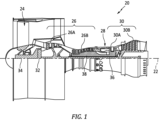
FIG. 1 is a diagrammatic sectional view of a gas turbine engine. -
FIG. 2 is a diagrammatic perspective view of an integrally bladed rotor. -
FIG. 3 is a diagrammatic perspective view of a rotor blade attached to an integrally bladed rotor hub. -
FIG. 4 is a diagrammatic perspective view of an airfoil. -
FIGS. 5 and 5A are diagrammatic views of a generic rotor blade, illustrating sectional cut lines. -
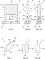
FIG. 6 is a diagrammatic sectional view of a present invention rotor blade embodiment taken at the sectional cut line I-I as shown inFIG. 5 . -
FIG. 6A is a diagrammatic sectional view of a present invention rotor blade embodiment taken at the sectional cut line II-II as shown inFIG. 5A . -
FIG. 6B is a diagrammatic sectional view of a present invention rotor blade embodiment taken at the sectional cut line II-II as shown inFIG. 5A . -
FIG. 7 is a diagrammatic perspective view of a damper body embodiment. -
FIG. 7A is a diagrammatic planar view of a damper body embodiment having a plurality of damper body components. -
FIG. 7B is a diagrammatic perspective view of a damper body embodiment. -
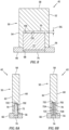
FIG. 8 is a diagrammatic sectional view of a present invention rotor blade embodiment taken at the sectional cut line I-I as shown inFIG. 5 . -
FIG. 8A is a diagrammatic sectional view of a present invention rotor blade embodiment taken at the sectional cut line II-II as shown inFIG. 5A . -
FIG. 8B is a diagrammatic sectional view of a present invention rotor blade embodiment taken at the sectional cut line II-II as shown inFIG. 5A . -
FIG. 9 is a diagrammatic sectional view of a present invention rotor blade embodiment taken at the sectional cut line I-I as shown inFIG. 5 . -
FIG. 9A is a diagrammatic sectional view of the rotor blade embodiment shown inFIG. 9 taken at the sectional cut line II-II as shown inFIG. 5A . -
FIG. 9B is a diagrammatic sectional view of the rotor blade embodiment shown inFIG. 9 taken at the sectional cut line III-III as shown inFIG. 5A . -
FIG. 10 is a diagrammatic sectional view of a present invention rotor blade embodiment taken at the sectional cut line I-I as shown inFIG. 5 . -
FIG. 10A is a diagrammatic sectional view of the rotor blade embodiment shown inFIG. 10 taken at the sectional cut line II-II as shown inFIG. 5A . -
FIG. 10B is a diagrammatic sectional view of the rotor blade embodiment shown inFIG. 10 taken at the sectional cut line III-III as shown inFIG. 5A . -
FIG. 11 is a diagrammatic sectional view of a present invention rotor blade embodiment taken at the sectional cut line I-I as shown inFIG. 5 . -
FIG. 11A is a diagrammatic sectional view of the rotor blade embodiment shown inFIG. 11 taken at the sectional cut line II-II as shown inFIG. 5A . -
FIG. 11B is a diagrammatic sectional view of the rotor blade embodiment shown inFIG. 11 taken at the sectional cut line III-III as shown inFIG. 5A . -
FIG. 1 shows a partially sectioned diagrammatic view of a gearedgas turbine engine 20. Thegas turbine engine 20 extends along anaxial centerline 22 between an upstream air flow inlet and a downstream air flow exhaust. Thegas turbine engine 20 includes afan section 24, acompressor section 26, acombustor section 28, and aturbine section 30. The compressor section includes alow pressure compressor 26A (LPC) and ahigh pressure compressor 26B (HPC). Theturbine section 30 includes ahigh pressure turbine 30A (HPT) and alow pressure turbine 30B (LPT). Theengine 20 sections are arranged sequentially along thecenterline 22. Thefan section 24 is connected to a gearedarchitecture 32, for example, through afan shaft 34. The gearedarchitecture 32 and theLPC 26A are connected to and driven by theLPT 30B through alow speed shaft 36. TheHPC 26B is connected to and driven by theHPT 30A through ahigh speed shaft 38. The terms "forward", "leading", "aft, "trailing" are used herein to indicate the relative position of a component or surface. As core gas air passes through theengine 20, a "leading edge" of a stator vane or rotor blade encounters core gas air before the "trailing edge" of the same. In a conventional axial engine such as that shown inFIG. 1 , thefan section 24 is "forward" of thecompressor section 26 and theturbine section 30 is "aft" of thecompressor section 26. The terms "inner radial" and "outer radial" refer to relative radial positions from theengine centerline 22. An inner radial component or path is disposed radially closer to theengine centerline 22 than an outer radial component or path. Thegas turbine engine 20 diagrammatically shown is an example provided to facilitate the description herein. The present invention is not limited to any particular gas turbine engine configuration. - Referring to
FIG. 2 , an integrally bladed rotor 40 ("IBR") includes a plurality ofrotor blades 42 affixed to the outer radial periphery of adisk 44. Therotor blades 42 extend radially outwardly from thedisk 44 and are spaced apart one from another around the circumference of thedisk 44. AnIBR 40 may be used as a rotor within thefan section 24, thecompressor section 26, or theturbine section 30 of agas turbine engine 20. The present invention is detailed herein generically as anIBR 40, and thatIBR 40 and therotor blades 42 therewith are not limited to use in any particular rotary section of agas turbine engine 20 unless specifically indicated.IBRs 40 may be manufactured using several different techniques; e.g., via additive manufacturing, machining from a solid body of metal, or a weldment wherein the individual blades are attached to adisk 44. Aspects of the present invention are directed to IBRs 40 produced as a weldment with individual blades attached to adisk 44. - The
disk 44 is configured to rotate about an axial centerline; e.g., the engineaxial centerline 22. Thedisk 44 includes an outerradial hub 46 that includes an outerradial hub surface 48 to which therotor blades 42 are directly or indirectly attached. The outerradial hub 46 may assume a variety of different configurations; e.g., a solid hub, an apertured hub and the like. The present invention is not limited to anyparticular disk hub 46 configuration. Therotor blades 42 may be attached to the disk outerradial hub surface 48 using an attachment technique such as Linear Friction Welding (LFW). The present invention is not limited to any particular rotor blade attachment technique. - Referring to
FIGS. 3 and 4 , eachrotor blade 42 includes anairfoil 50 that extends chordwise between aleading edge 52 and a trailingedge 54, and extends spanwise between abase end 56 and ablade tip 58. In the assembledIBR 40, thebase end 56 of eachairfoil 50 is disposed radially inward of theblade tip 58. Theairfoil 50 includes asuction side surface 60 and apressure side surface 62 disposed opposite one another. The chord of theairfoil 50 is the distance between theleading edge 52 and the trailingedge 54. Thecamber line 64 of theairfoil 50 is an imaginary line which lies halfway between thesuction side surface 60 and thepressure side surface 62 of theairfoil 50 and intersects the chord line at the leading and trailingedges rotor blade 42 extends between thesuction side surface 60 and thepressure side surface 62.Airfoils 50 may be symmetrical (chord line andcamber line 64 coincident) or they may be cambered (chord line andcamber line 64 deviate from one another). The configuration of an airfoil 50 (e.g., cross-sectional area, camber, and the like) may be constant spanwise between thebase end 56 and theblade tip 58, or the configuration of anairfoil 50 may vary (e.g., different cross-sectional area, different camber, and the like) at different spanwise positions between thebase end 56 and theblade tip 58. The present invention is not limited to anyparticular airfoil 50 configuration other than as described herein. - In some present invention embodiments, a
rotor blade 42 may include a body referred to as a "weld collar 66" affixed to thebase end 56 of theairfoil 50 or integrally formed with theairfoil 50. Theweld collar 66 typically has a larger area "footprint" than theairfoil 50; e.g., an axial dimension that is greater than the chord of theairfoil 50 and a circumferential dimension (perpendicular to the axial direction) that is greater than the thickness of the airfoil 50 (or the degree to which theairfoil 50 is cambered). In these embodiments, theweld collar 66 of eachrotor blade 42 is attached to the disk outerradial hub 46. The present invention is not limited to anyparticular weld collar 66 configuration. Therotor blades 42 may be attached to the disk outerradial hub 46 using an attachment technique such as Linear Friction Welding (LFW). The present invention is not limited to any particular rotor blade attachment technique. The present invention is not limited to IBRs 40 havingrotor blades 42 affixed to (or integrally formed with) aweld collar 66. The present invention does not require the use ofweld collars 66. - As indicated herein, prior art IBRs of which we are aware typically have little or no mechanical damping and are often utilized in environments where high vibratory stresses can be induced within components of the
IBR 40; e.g., within therotor blades 42. The present invention provides structure that produces mechanical damping inIBR rotor blades 42 and that damping is understood to be effective in reducing high vibratory stresses and consequent high cycle fatigue (HCF) damage. As will be detailed herein, embodiments of the present invention include arotor blade 42 having adamper pocket 70, adamper body 72, and aplug 74. - Referring to
FIGS. 6-6B , arotor blade 42 is diagrammatically shown with adamper pocket 70 extending into theairfoil 50 from thebase end 56. InFIGS. 6-6B , therotor blade 42 is shown with aweld collar 66 affixed to thebase end 56 of theairfoil 50. Theweld collar 66 includes an aperture ("weld collar aperture 68") that provides access to thedamper pocket 70 within theairfoil 50 of therotor blade 42.FIG. 6 is a sectional view taken at the sectional cut line I-I as shown inFIG. 5 andFIGS. 6A and 6B are sectional views taken at the sectional cut line II-II as shown inFIG. 5A . It should be noted thatFIGS. 5 and 5A are provided to illustrate the positioning of sectional cut lines in the various embodiments described herein. Thus,FIGS. 5 and 5A are generically representative of the various embodiments, and specific details of the various embodiments are shown in other FIGURES of the present application. - In some embodiments, the
damper pocket 70 may include four sides; e.g., like that shown inFIGS. 6 and 6A wherein thedamper pocket 70 has a pocket leading edge ("PLE")surface 70A (disposed on thepocket 70 side closest to the airfoil leading edge 52), a pocket trailing edge ("PTE")surface 70B (disposed on thepocket 70 side closest to the airfoil trailing edge 54), a pocket suction side ("PSS")surface 70C (disposed on thepocket 70 side closest to the airfoil suction side 60), and a pocket pressure side ("PPS")surface 70D (disposed on thepocket 70 side closest to the airfoil pressure side 62). Thedamper pocket 70 diagrammatically shown inFIGS. 6 and 6A may be described as having a fifth side surface (a pockettop surface 70E). The PLE and PTE surfaces 70A, 70B may be parallel one another or one or both may converge towards the other. The PSS andPPS damper pocket 70 may have fewer than four (4) pocket surfaces or more than four (4) pocket surfaces. An example of adamper pocket 70 that has fewer than four (4) pocket surfaces (i.e., a one side surface and one top surface) is shown inFIGS. 9-9B wherein thedamper pocket 70 is formed as a truncated cone with a singlearcuate wall surface 70F and atop surface 70E. InFIGS. 6 and 6A , theweld collar aperture 68 is shown as a uniform shape; e.g., constant width and thickness. The present invention is not limited to aweld collar aperture 68 that is uniformly shaped (e.g., as shown inFIG. 6A ); e.g., in those embodiments wherein thedamper pocket 70 has a converging surfaces configuration, theweld collar aperture 68 may also have a converging configuration (e.g., as shown inFIG. 6B ). - Embodiments of the present invention also include at least one
damper body 72 configured to be received within and mate with thedamper pocket 70 of arotor blade 42.FIGS. 7 and 7B illustrate aunitary damper body 72 andFIG. 7A illustrates adamper body 72 comprising a plurality ofdamper body components 72A-C. Thespecific damper body 72 example shown inFIG. 7A includes a first tapereddamper body component 72A, a second tapereddamper body component 72B, and acentral body component 72C. The present invention is not limited to thesedamper body 72 examples; e.g., presentinvention damper bodies 72 may be unitary or have two or more damper body components, and are not limited to any particular geometric configuration. As stated above, a presentinvention damper body 72 is configured to "mate" with adamper pocket 70 of arotor blade 42. The term "mate" is used to indicate that thedamper body 72 is at least partially received within thedamper pocket 70, and is generally configured so that one or more surfaces of thedamper body 72 are disposed in contact with one or more surfaces of thedamper pocket 70. For example, if the rotorblade damper pocket 70 includes four side surfaces, thedamper body 72 may include four side wall surfaces; if the rotorblade damper pocket 70 has a single side wall surface (e.g., adamper pocket 70 configured as a truncated cone - seeFIG. 7B ), then thedamper body 72 may have a mating configuration (i.e., a truncated cone) to create the mating relationship between thedamper pocket 70 and thedamper body 72.FIG. 7 diagrammatically illustrates adamper body 72 having a tapered configuration defined by a damper body suction side (DBSS)surface 72A, a damper body pressure side (DBPS)surface 72B, a damper body leading edge (DBLE)side surface 72C, a damper body trailing edge (DBTE)side surface 72D, a damper body top side (DBTS)surface 72E, and a damper body bottom side (DBBS)surface 72F. In this embodiment, both theDBSS surface 72A and theDBPS surface 72B converge toward one another in a direction from theDBBS surface 72F towards theDBTS surface 72E; i.e., a tapered configuration.FIG. 7B diagrammatically illustrates adamper body 72 having a tapered configuration defined by a damperbody side surface 72G, a damper bodytop surface 72E, and a damperbody bottom surface 72F. In this embodiment, the damper body 72 (configured as a truncated cone) converges in a direction from the damperbottom surface 72F to the dampertop surface 72E. As indicated above, the present invention is not limited to thesedamper body 72 configuration examples, and the present invention is not limited to anyparticular damper body 72 geometric configuration. - The
plug 74 is a body that may be utilized to maintain thedamper body 72 within thedamper pocket 70. In thoserotor blade 42 embodiments that include aweld collar 66, theplug 74 may be configured to be received within theweld collar aperture 68. In thoserotor blade 42 embodiments that do not include aweld collar 66, theplug 74 may be configured to be received within a portion of thedamper pocket 70. Theplug 74 is affixed to the weld collar 66 (or airfoil 50) after thedamper body 72 is inserted into thedamper pocket 70. Theplug 74 may be affixed by weldment, or mechanical fastener, or the like. Theplug 74 may comprise the same material as thedamper body 72, or the same material as theweld collar 66, or a different material. -
FIGS. 8-8B diagrammatically illustrate a presentinvention rotor blade 42 embodiment having aweld collar 66.FIG. 8 is a sectional view taken at the sectional cut line I-I as shown inFIG. 5 andFIGS. 8A and 8B are sectional views taken at the sectional cut line II-II as shown inFIG. 5A .FIG. 8A diagrammatically illustrates aunitary damper body 72 and adamper pocket 70, each respectively having a pair of converging surfaces that mate with the converging surfaces of the other.FIG. 8B diagrammatically illustrates adamper body 72 example like that shown inFIG. 7A that includes a first tapereddamper body component 72A, a second tapereddamper body component 72B, and a centraldamper body component 72C. The first and second tapereddamper body components damper pocket 70. The embodiments diagrammatically shown inFIGS. 8-8B include aplug 74 disposed in theweld collar aperture 68. - In some embodiments (like that shown in
FIGS. 8-8B ), the depth of thedamper pocket 70 may exceed the length of thedamper body 72 when thedamper body 72 is fully received within thedamper pocket 70; e.g., the difference shown as depth gap "DG" inFIG. 8 . In similar fashion, theplug 74 may not fill the entireweld collar aperture 68. As will be detailed herein, additional space may be allowed on either side of thedamper body 72 to accommodatedamper body 72 movement. -
FIGS. 9-9B diagrammatically illustrate a presentinvention rotor blade 42 embodiment having aweld collar 66.FIG. 9 is a sectional view taken at the sectional cut line I-I as shown inFIG. 5 ,FIG. 9A is a sectional views taken at the sectional cut line II-II as shown inFIG. 5A , andFIG. 9B is a sectional views taken at the sectional cut line III-III as shown inFIG. 5A .FIGS. 9-9B diagrammatically illustrate aunitary damper body 72 configured as a truncated cone disposed in adamper pocket 70 configured as a truncated cone. The embodiments diagrammatically shown inFIGS. 9-9B include aplug 74 disposed in eachweld collar aperture 68. -
FIGS. 10-10B diagrammatically illustrate a presentinvention rotor blade 42 embodiment having aweld collar 66.FIG. 10 is a sectional view taken at the sectional cut line I-I as shown inFIG. 5 ,FIG. 10A is a sectional views taken at the sectional cut line II-II as shown inFIG. 5A , andFIG. 10B is a sectional views taken at the sectional cut line III-III as shown inFIG. 5A .FIGS. 10-10B diagrammatically illustrate a plurality ofdamper bodies 72, each comprising a plurality of damper body components 172A-C. In this specific example, eachdamper body 72 includes three nested truncated cones; e.g., a first damper body component 172A in the form of a hollow truncated cone configured to engage with the side wall of adamper pocket 70 formed as a truncated cone, a second damper body component 172B in the form of a hollow truncated cone configured to engage with a truncated cone pocket disposed in the first damper body component 172A, and a third damper body component 172C in the form of a truncated cone configured to engage with a truncated cone pocket disposed in the second damper body component 172B. The embodiments diagrammatically shown inFIGS. 10-10B include aplug 74 disposed in eachweld collar aperture 68. -
FIGS. 11-11B diagrammatically illustrate a presentinvention rotor blade 42 embodiment having aweld collar 66.FIG. 11 is a sectional view taken at the sectional cut line I-I as shown inFIG. 5 ,FIG. 11A is a sectional views taken at the sectional cut line II-II as shown inFIG. 5A , andFIG. 11B is a sectional views taken at the sectional cut line III-III as shown inFIG. 5A .FIGS. 11-11B diagrammatically illustrate a present invention embodiment wherein a plurality of damper bodies (each shown as a unitary damper body 72 - but not limited thereto) are disposed within damper pockets 70 disposed along acamber line 64 of acambered airfoil 50. The plurality of damper bodies and damper pockets 70 are understood to be useful inrotor blades 42 having acambered airfoil 50; e.g., where the configuration of asingle damper pocket 70 /damper body 72 may otherwise be limited limit in view of the cambering. The embodiments diagrammatically shown inFIGS. 11-11B include aplug 74 disposed in eachweld collar aperture 68. - The
damper body 72 may comprise a variety of different materials. As will be detailed herein, thedamper body 72 is configured to frictionally engage with thedamper pocket 70 and the frictional engagement therebetween produces a dissipation of vibrational energy and consequent damping of undesirable vibrational modes that may produce high vibratory stresses and High Cycle Fatigue (HCF) damage.Damper body 72 embodiments may comprise any material that is capable of producing the frictional engagement between thedamper body 72 and thedamper pocket 70 that produces the desired vibrational energy dissipation. In some embodiments, adamper body 72 may be formed from a shape memory alloy ("SMA"); e.g., a metal alloy that may be deformed under certain operating conditions and "remembers" its' shape prior to being deformed. It is understood that in some applications, adamper body 72 formed from a SMA may provide additional inherent damping during material phase changes that theSMA damper body 72 experiences. - In the manufacturing of a
present invention IBR 40, a damper body 72 (a unitary body or a collective body formed from a plurality of components) is disposed within thedamper pocket 70 of arotor blade 42 to be attached to thedisk 44 of theIBR 40. The mating tapered configurations of thedamper body 72 and thedamper pocket 70 are chosen so that at least one side surface of thedamper body 72 engages with a side surface of thedamper pocket 70. As indicated, the depth of thedamper pocket 70 may exceed the length of thedamper body 72 when thedamper body 72 is fully received within thedamper pocket 70. In thoserotor blade 42 embodiments that include aweld collar 66, thedamper body 72 may extend into theweld collar aperture 68. After thedamper body 72 is disposed within thedamper pocket 70 /weld collar 66, theplug 74 is inserted into theweld collar aperture 68 and is affixed (e.g., welded) to theweld collar 66. Therotor blade 42 is subsequently attached to thedisk hub 46; e.g., via a linear friction welding (LFW) technique. Theplug 74 provides an interface between thedamper body 72 and theweld collar 66 surface attached to thedisk 44 to prevent the rotor blade attachment technique (e.g., LFW) from adversely affecting thedamper body 72 during the rotor blade attachment process. - In the operation of the
IBR 40, thedamper body 72 disposed within eachrotor blade 42 portion of theIBR 40 will be subject to centrifugal force as theIBR 40 rotates within theengine 20. The mating tapered configurations of thedamper body 72 and thedamper pocket 70 facilitates contact between the respective tapered surfaces; e.g., the faster theIBR 40 rotates, the greater the normal force produced by the mass of the damper on the pocket surface. Over time, one or both of thedamper body 72 anddamper pocket 70 tapered surfaces may frictionally wear. The mating tapered configurations of thedamper body 72 and thedamper pocket 70 ensure that the desired frictional contact will be maintained. In those embodiments wherein the depth of thedamper pocket 70 exceeds the length of thedamper body 72 when thedamper body 72 is fully received within the damper pocket 70 (e.g., difference "DG" - seeFIG. 8 ), the gap therebetween allows for some amount ofdamper body 72 positional change as a result of frictional wear and the desired dissipation of vibrational energy regardless of the frictional wear. - While the principles of the invention have been described above in connection with specific apparatuses and methods, it is to be clearly understood that this description is made only by way of example and not as limitation on the scope of the invention. Specific details are given in the above description to provide a thorough understanding of the embodiments. However, it is understood that the embodiments may be practiced without these specific details.
- It is noted that the embodiments may be described as a process which is depicted as a flowchart, a flow diagram, a block diagram, etc. Although any one of these structures may describe the operations as a sequential process, many of the operations can be performed in parallel or concurrently. In addition, the order of the operations may be rearranged. A process may correspond to a method, a function, a procedure, a subroutine, a subprogram, etc.
- The singular forms "a," "an," and "the" refer to one or more than one, unless the context clearly dictates otherwise. For example, the term "comprising a specimen" includes single or plural specimens and is considered equivalent to the phrase "comprising at least one specimen." The term "or" refers to a single element of stated alternative elements or a combination of two or more elements unless the context clearly indicates otherwise. As used herein, "comprises" means "includes." Thus, "comprising A or B," means "including A or B, or A and B," without excluding additional elements.
- It is noted that various connections are set forth between elements in the present description and drawings (the contents of which are included in this invention by way of reference). It is noted that these connections are general and, unless specified otherwise, may be direct or indirect and that this specification is not intended to be limiting in this respect. Any reference to attached, fixed, connected or the like may include permanent, removable, temporary, partial, full and/or any other possible attachment option.
- As used herein, the terms "comprise", "comprising", or any other variation thereof, are intended to cover a non-exclusive inclusion, such that a process, method, article, or apparatus that comprises a list of elements does not include only those elements but may include other elements not expressly listed or inherent to such process, method, article, or apparatus.
- While various inventive aspects, concepts and features of the invention may be described and illustrated herein as embodied in combination in the exemplary embodiments, these various aspects, concepts, and features may be used in many alternative embodiments, either individually or in various combinations and sub-combinations thereof. Unless expressly excluded herein all such combinations and sub-combinations are intended to be within the scope of the present application. Still further, while various alternative embodiments as to the various aspects, concepts, and features of the invention--such as alternative materials, structures, configurations, methods, devices, and components, and so on--may be described herein, such descriptions are not intended to be a complete or exhaustive list of available alternative embodiments, whether presently known or later developed. Those skilled in the art may readily adopt one or more of the inventive aspects, concepts, or features into additional embodiments and uses within the scope of the present application even if such embodiments are not expressly disclosed herein. For example, in the exemplary embodiments described above within the Detailed Description portion of the present specification, elements may be described as individual units and shown as independent of one another to facilitate the description. In alternative embodiments, such elements may be configured as combined elements. It is further noted that various method or process steps for embodiments of the present invention are described herein. The description may present method and/or process steps as a particular sequence. However, to the extent that the method or process does not rely on the particular order of steps set forth herein, the method or process should not be limited to the particular sequence of steps described. As one of ordinary skill in the art would appreciate, other sequences of steps may be possible.
Claims (15)
- An integrally bladed disk, comprising:a disk having an outer radial hub, the disk configured for rotation around a rotational axis;a plurality of rotor blades, each having an airfoil, the airfoil extending chordwise between a leading edge and a trailing edge, and extending spanwise between a base end and a blade tip, wherein each said rotor blade includes:a damper pocket extending into the airfoil from the base end, the damper pocket having a first tapered configuration;a damper body disposed within the damper pocket, wherein the damper body has a second tapered configuration, and the second tapered configuration of the damper body mates with the first tapered configuration of the damper pocket; anda plug disposed to retain the damper body within the damper pocket.
- The integrally bladed disk of claim 1, wherein each said rotor blade includes a weld collar affixed to the base end of the airfoil, and the weld collar includes a weld collar aperture that is aligned with the damper pocket and configured to receive the damper body.
- The integrally bladed disk of claim 2, wherein the plug for each said rotor blade is affixed to the weld collar.
- The integrally bladed disk of claim 2 or 3, wherein each said rotor blade is affixed to the outer radial hub of the disk at the weld collar.
- The integrally bladed disk of any preceding claim, wherein:the first tapered configuration of the damper pocket (DP) includes a first DP side surface and a second DP side surface, and the first DP side surface and the second DP side surface converge toward one another; andthe second tapered configuration of the damper body (DB) includes a first DB side surface and a second DB side surface, and the first DB side surface and the second DB side surface converge toward one another.
- The integrally bladed disk of claim 5, wherein:the damper pocket includes a DP top end surface that extends between the first DP side surface and the second DP side surface;the damper body includes a DB top end surface that extends between the first DB side surface and the second DB side surface;the damper pocket and the damper body are disposable in an engaged configuration wherein the first DP side surface is in contact with the first DB side surface and the second DP side surface is in contact with the second DB side surface; andin the engaged configuration, the DB top end surface is spaced apart from the DP top end surface.
- The integrally bladed disk of any of claims 1 to 4, whereinthe first tapered configuration of the damper pocket (DP) includes a DP top side surface and a single DP side surface that extends circumferentially and extends spanwise from the airfoil base end to the DP top side surface, and converges in a direction from the airfoil base end to the DP top side surface; andthe second tapered configuration of the damper body (DB) includes a DB top side surface, a DB bottom side surface, and a single DB side surface that extends circumferentially and extends between the DB bottom side surface to the DB top side surface, and converges in a direction from the DB bottom side surface to the DB top side surface.
- The integrally bladed disk of claim 7, wherein the first tapered configuration of the damper pocket is a first truncated cone, and the second tapered configuration of the damper body is a second truncated cone, and the damper pocket and the damper body are disposable in an engaged configuration wherein the single DB side surface is in contact with the single DP side surface,
optionally wherein in the engaged configuration, the DB top side surface is spaced apart from the DP top side surface. - The integrally bladed disk of any preceding claim, wherein the damper body is a unitary body.
- The integrally bladed disk of any of claims 1 to 8, wherein the damper body includes a plurality of components that collectively form the damper body.
- The integrally bladed disk of claim 10 when dependent on claim 5, wherein the plurality of components that collectively form the damper body includes a first tapered damper body component, a second tapered damper body component, and a central damper body component.
- The integrally bladed disk of claim 10 when dependent on claim 7, wherein the plurality of components that collectively form the damper body includes a first damper body component and a second damper body component, and the second damper body component nests within the first damper body component.
- The integrally bladed disk of any preceding claim, wherein the damper body comprises a shape memory alloy.
- A rotor blade portion for an integrally bladed disk, the rotor blade portion comprising:an airfoil extending chordwise between a leading edge and a trailing edge, and extending spanwise between a base end and a blade tip;a damper pocket extending into the airfoil from the base end, the damper pocket having a first tapered configuration;a damper body disposed within the damper pocket, wherein the damper body has a second tapered configuration, and the second tapered configuration of the damper body mates with the first tapered configuration of the damper pocket;a weld collar affixed to the base end of the airfoil, the weld collar including a weld collar aperture that is aligned with the damper pocket and configured to receive the damper body; anda plug disposed within the weld collar aperture and affixed to the weld collar, optionally wherein:the first tapered configuration of the damper pocket (DP) includes a first DP side surface and a second DP side surface, and the first DP side surface and the second DP side surface converge toward one another; andthe second tapered configuration of the damper body (DB) includes a first DB side surface and a second DB side surface, and the first DB side surface and the second DB side surface converge toward one another, and further optionally wherein:the damper pocket includes a DP top end surface that extends between the first DP side surface and the second DP side surface;the damper body includes a DB top end surface that extends between the first DB side surface and the second DB side surface;the damper pocket and the damper body are disposable in an engaged configuration wherein the first DP side surface is in contact with the first DB side surface and the second DP side surface is in contact with the second DB side surface; andin the engaged configuration, the DB top end surface is spaced apart from the DP top end surface.
- The rotor blade portion of claim 14, wherein:the first tapered configuration of the damper pocket (DP) includes a DP top side surface and a single DP side surface that extends circumferentially and extends spanwise from the airfoil base end to the DP top side surface, and converges in a direction from the airfoil base end to the DP top side surface; andthe second tapered configuration of the damper body (DB) includes a DB top side surface, a DB bottom side surface, and a single DB side surface that extends circumferentially and extends between the DB bottom side surface to the DB top side surface, and converges in a direction from the DB bottom side surface to the DB top side surface.
Applications Claiming Priority (1)
| Application Number | Priority Date | Filing Date | Title |
|---|---|---|---|
| US18/400,695 US12371999B2 (en) | 2023-12-29 | 2023-12-29 | Damping system for an integrally bladed rotor |
Publications (1)
| Publication Number | Publication Date |
|---|---|
| EP4579060A1 true EP4579060A1 (en) | 2025-07-02 |
Family
ID=94117068
Family Applications (1)
| Application Number | Title | Priority Date | Filing Date |
|---|---|---|---|
| EP24223244.5A Pending EP4579060A1 (en) | 2023-12-29 | 2024-12-24 | Integrally bladed disk and rotor blade portion for an integrally bladed disk |
Country Status (2)
| Country | Link |
|---|---|
| US (2) | US12371999B2 (en) |
| EP (1) | EP4579060A1 (en) |
Citations (3)
| Publication number | Priority date | Publication date | Assignee | Title |
|---|---|---|---|---|
| US20030194324A1 (en) * | 2002-04-11 | 2003-10-16 | Davis Gary A. | Turbine blade assembly with pin dampers |
| US20060120875A1 (en) * | 2004-02-13 | 2006-06-08 | United Technologies Corporation | Cooled rotor blade with vibration damping device |
| US20170044910A1 (en) * | 2015-08-12 | 2017-02-16 | MTU Aero Engines AG | Bladed gas turbine rotor |
Family Cites Families (15)
| Publication number | Priority date | Publication date | Assignee | Title |
|---|---|---|---|---|
| US1833754A (en) * | 1930-08-22 | 1931-11-24 | Gen Electric | Vibration damping by impact |
| US2984453A (en) * | 1957-03-25 | 1961-05-16 | Westinghouse Electric Corp | Vibration damper for blading in elastic fluid apparatus |
| GB9906450D0 (en) * | 1999-03-19 | 1999-05-12 | Rolls Royce Plc | Aerofoil blade damper |
| GB0100695D0 (en) * | 2001-01-11 | 2001-02-21 | Rolls Royce Plc | a turbomachine blade |
| US6699015B2 (en) | 2002-02-19 | 2004-03-02 | The Boeing Company | Blades having coolant channels lined with a shape memory alloy and an associated fabrication method |
| US6796408B2 (en) | 2002-09-13 | 2004-09-28 | The Boeing Company | Method for vibration damping using superelastic alloys |
| GB2405186B (en) * | 2003-08-20 | 2005-10-26 | Rolls Royce Plc | A component with internal damping |
| GB0615144D0 (en) * | 2006-07-29 | 2006-09-06 | Rolls Royce Plc | Turbomachine blade |
| US8267662B2 (en) | 2007-12-13 | 2012-09-18 | General Electric Company | Monolithic and bi-metallic turbine blade dampers and method of manufacture |
| GB2468528B (en) | 2009-03-13 | 2011-03-30 | Rolls Royce Plc | Vibration damper |
| FR2950382B1 (en) | 2009-09-21 | 2013-07-19 | Snecma | PIECE COMPRISING A SHAPE MEMORY ALLOY STRUCTURE AND ELEMENT |
| US11136888B2 (en) * | 2018-10-18 | 2021-10-05 | Raytheon Technologies Corporation | Rotor assembly with active damping for gas turbine engines |
| US11371358B2 (en) * | 2020-02-19 | 2022-06-28 | General Electric Company | Turbine damper |
| US11767765B2 (en) * | 2021-09-28 | 2023-09-26 | General Electric Company | Glass viscous damper |
| US20230117555A1 (en) | 2021-10-15 | 2023-04-20 | Raytheon Technologies Corporation | Blade vibration mitigation of integrally bladed rotor by damping on disk |
-
2023
- 2023-12-29 US US18/400,695 patent/US12371999B2/en active Active
-
2024
- 2024-12-24 EP EP24223244.5A patent/EP4579060A1/en active Pending
-
2025
- 2025-07-28 US US19/282,728 patent/US20250354497A1/en active Pending
Patent Citations (3)
| Publication number | Priority date | Publication date | Assignee | Title |
|---|---|---|---|---|
| US20030194324A1 (en) * | 2002-04-11 | 2003-10-16 | Davis Gary A. | Turbine blade assembly with pin dampers |
| US20060120875A1 (en) * | 2004-02-13 | 2006-06-08 | United Technologies Corporation | Cooled rotor blade with vibration damping device |
| US20170044910A1 (en) * | 2015-08-12 | 2017-02-16 | MTU Aero Engines AG | Bladed gas turbine rotor |
Also Published As
| Publication number | Publication date |
|---|---|
| US12371999B2 (en) | 2025-07-29 |
| US20250354497A1 (en) | 2025-11-20 |
| US20250215799A1 (en) | 2025-07-03 |
Similar Documents
| Publication | Publication Date | Title |
|---|---|---|
| JP3948926B2 (en) | Method and apparatus for reducing circumferential rim stress in a rotor assembly | |
| US6524070B1 (en) | Method and apparatus for reducing rotor assembly circumferential rim stress | |
| CA2313929C (en) | Reduced-stress compressor blisk flowpath | |
| US8403645B2 (en) | Turbofan flow path trenches | |
| EP2080578B1 (en) | Linear friction welded blisk and method of fabrication | |
| JP5450997B2 (en) | Rotor blade | |
| US20190128126A1 (en) | Turbine blisk and method of manufacturing thereof | |
| EP3453484B1 (en) | Process of making integrally bladed rotor and integrally bladed rotor | |
| WO2013188778A1 (en) | Compressor blade | |
| CN110573697A (en) | Turbine frame and bearing arrangement for a three-shaft engine | |
| EP3048248A1 (en) | Rotor disk boss | |
| EP3453483A1 (en) | Method of making integrally bladed rotor | |
| EP3143259B1 (en) | Method of manufacturing a component of a turbomachine, component of a turbomachine and turbomachine | |
| JP2006348937A (en) | Turbine blade and method of manufacturing the same | |
| CN103025480A (en) | Process for manufacturing a turbomachine drum | |
| CN111936723B (en) | Detuning of turbine blades with one or more internal cavities | |
| US12371999B2 (en) | Damping system for an integrally bladed rotor | |
| EP4439036B1 (en) | Test blade for gas turbine engine and method of making | |
| EP4269751A1 (en) | Method of manufacturing a mistuned rotor | |
| US12404775B1 (en) | Turbine blade with cooling channels | |
| US12565840B1 (en) | Axial compressor rotor assembly | |
| EP4345249A1 (en) | Stator vane for a gas turbine engine | |
| EP4663900A1 (en) | Shrouded turbine assembly for a gas turbine engine | |
| US20170198584A1 (en) | Systems and methods for repairing a component of a rotary machine | |
| EP3604738A1 (en) | Laser tip cladding to net-shape with backing elements |
Legal Events
| Date | Code | Title | Description |
|---|---|---|---|
| PUAI | Public reference made under article 153(3) epc to a published international application that has entered the european phase |
Free format text: ORIGINAL CODE: 0009012 |
|
| STAA | Information on the status of an ep patent application or granted ep patent |
Free format text: STATUS: THE APPLICATION HAS BEEN PUBLISHED |
|
| AK | Designated contracting states |
Kind code of ref document: A1 Designated state(s): AL AT BE BG CH CY CZ DE DK EE ES FI FR GB GR HR HU IE IS IT LI LT LU LV MC ME MK MT NL NO PL PT RO RS SE SI SK SM TR |
|
| STAA | Information on the status of an ep patent application or granted ep patent |
Free format text: STATUS: REQUEST FOR EXAMINATION WAS MADE |
|
| 17P | Request for examination filed |
Effective date: 20251230 |
|
| RIN1 | Information on inventor provided before grant (corrected) |
Inventor name: MCCASLIN, LUCAS O. Inventor name: BONARRIGO, STEPHEN B. |
|
| GRAP | Despatch of communication of intention to grant a patent |
Free format text: ORIGINAL CODE: EPIDOSNIGR1 |
|
| STAA | Information on the status of an ep patent application or granted ep patent |
Free format text: STATUS: GRANT OF PATENT IS INTENDED |
|
| RIC1 | Information provided on ipc code assigned before grant |
Ipc: F01D 5/16 20060101AFI20260205BHEP Ipc: F01D 5/34 20060101ALI20260205BHEP |
|
| INTG | Intention to grant announced |
Effective date: 20260309 |