EP4578987A1 - Plated steel sheet for hot press forming having excellent impact resistance, hot press formed part, and manufacturing methods thereof - Google Patents
Plated steel sheet for hot press forming having excellent impact resistance, hot press formed part, and manufacturing methods thereof Download PDFInfo
- Publication number
- EP4578987A1 EP4578987A1 EP23857642.5A EP23857642A EP4578987A1 EP 4578987 A1 EP4578987 A1 EP 4578987A1 EP 23857642 A EP23857642 A EP 23857642A EP 4578987 A1 EP4578987 A1 EP 4578987A1
- Authority
- EP
- European Patent Office
- Prior art keywords
- steel sheet
- less
- content
- present disclosure
- carbon
- Prior art date
- Legal status (The legal status is an assumption and is not a legal conclusion. Google has not performed a legal analysis and makes no representation as to the accuracy of the status listed.)
- Pending
Links
Images


Classifications
-
- C—CHEMISTRY; METALLURGY
- C23—COATING METALLIC MATERIAL; COATING MATERIAL WITH METALLIC MATERIAL; CHEMICAL SURFACE TREATMENT; DIFFUSION TREATMENT OF METALLIC MATERIAL; COATING BY VACUUM EVAPORATION, BY SPUTTERING, BY ION IMPLANTATION OR BY CHEMICAL VAPOUR DEPOSITION, IN GENERAL; INHIBITING CORROSION OF METALLIC MATERIAL OR INCRUSTATION IN GENERAL
- C23C—COATING METALLIC MATERIAL; COATING MATERIAL WITH METALLIC MATERIAL; SURFACE TREATMENT OF METALLIC MATERIAL BY DIFFUSION INTO THE SURFACE, BY CHEMICAL CONVERSION OR SUBSTITUTION; COATING BY VACUUM EVAPORATION, BY SPUTTERING, BY ION IMPLANTATION OR BY CHEMICAL VAPOUR DEPOSITION, IN GENERAL
- C23C2/00—Hot-dipping or immersion processes for applying the coating material in the molten state without affecting the shape; Apparatus therefor
- C23C2/04—Hot-dipping or immersion processes for applying the coating material in the molten state without affecting the shape; Apparatus therefor characterised by the coating material
- C23C2/12—Aluminium or alloys based thereon
-
- C—CHEMISTRY; METALLURGY
- C21—METALLURGY OF IRON
- C21D—MODIFYING THE PHYSICAL STRUCTURE OF FERROUS METALS; GENERAL DEVICES FOR HEAT TREATMENT OF FERROUS OR NON-FERROUS METALS OR ALLOYS; MAKING METAL MALLEABLE, e.g. BY DECARBURISATION OR TEMPERING
- C21D1/00—General methods or devices for heat treatment, e.g. annealing, hardening, quenching or tempering
- C21D1/18—Hardening; Quenching with or without subsequent tempering
-
- C—CHEMISTRY; METALLURGY
- C21—METALLURGY OF IRON
- C21D—MODIFYING THE PHYSICAL STRUCTURE OF FERROUS METALS; GENERAL DEVICES FOR HEAT TREATMENT OF FERROUS OR NON-FERROUS METALS OR ALLOYS; MAKING METAL MALLEABLE, e.g. BY DECARBURISATION OR TEMPERING
- C21D1/00—General methods or devices for heat treatment, e.g. annealing, hardening, quenching or tempering
- C21D1/62—Quenching devices
- C21D1/673—Quenching devices for die quenching
-
- C—CHEMISTRY; METALLURGY
- C21—METALLURGY OF IRON
- C21D—MODIFYING THE PHYSICAL STRUCTURE OF FERROUS METALS; GENERAL DEVICES FOR HEAT TREATMENT OF FERROUS OR NON-FERROUS METALS OR ALLOYS; MAKING METAL MALLEABLE, e.g. BY DECARBURISATION OR TEMPERING
- C21D1/00—General methods or devices for heat treatment, e.g. annealing, hardening, quenching or tempering
- C21D1/74—Methods of treatment in inert gas, controlled atmosphere, vacuum or pulverulent material
- C21D1/76—Adjusting the composition of the atmosphere
-
- C—CHEMISTRY; METALLURGY
- C21—METALLURGY OF IRON
- C21D—MODIFYING THE PHYSICAL STRUCTURE OF FERROUS METALS; GENERAL DEVICES FOR HEAT TREATMENT OF FERROUS OR NON-FERROUS METALS OR ALLOYS; MAKING METAL MALLEABLE, e.g. BY DECARBURISATION OR TEMPERING
- C21D3/00—Diffusion processes for extraction of non-metals; Furnaces therefor
- C21D3/02—Extraction of non-metals
- C21D3/04—Decarburising
-
- C—CHEMISTRY; METALLURGY
- C21—METALLURGY OF IRON
- C21D—MODIFYING THE PHYSICAL STRUCTURE OF FERROUS METALS; GENERAL DEVICES FOR HEAT TREATMENT OF FERROUS OR NON-FERROUS METALS OR ALLOYS; MAKING METAL MALLEABLE, e.g. BY DECARBURISATION OR TEMPERING
- C21D8/00—Modifying the physical properties of ferrous metals or ferrous alloys by deformation combined with, or followed by, heat treatment
- C21D8/02—Modifying the physical properties of ferrous metals or ferrous alloys by deformation combined with, or followed by, heat treatment during manufacturing of plates or strips
-
- C—CHEMISTRY; METALLURGY
- C21—METALLURGY OF IRON
- C21D—MODIFYING THE PHYSICAL STRUCTURE OF FERROUS METALS; GENERAL DEVICES FOR HEAT TREATMENT OF FERROUS OR NON-FERROUS METALS OR ALLOYS; MAKING METAL MALLEABLE, e.g. BY DECARBURISATION OR TEMPERING
- C21D8/00—Modifying the physical properties of ferrous metals or ferrous alloys by deformation combined with, or followed by, heat treatment
- C21D8/02—Modifying the physical properties of ferrous metals or ferrous alloys by deformation combined with, or followed by, heat treatment during manufacturing of plates or strips
- C21D8/0221—Modifying the physical properties of ferrous metals or ferrous alloys by deformation combined with, or followed by, heat treatment during manufacturing of plates or strips characterised by the working steps
- C21D8/0226—Hot rolling
-
- C—CHEMISTRY; METALLURGY
- C21—METALLURGY OF IRON
- C21D—MODIFYING THE PHYSICAL STRUCTURE OF FERROUS METALS; GENERAL DEVICES FOR HEAT TREATMENT OF FERROUS OR NON-FERROUS METALS OR ALLOYS; MAKING METAL MALLEABLE, e.g. BY DECARBURISATION OR TEMPERING
- C21D8/00—Modifying the physical properties of ferrous metals or ferrous alloys by deformation combined with, or followed by, heat treatment
- C21D8/02—Modifying the physical properties of ferrous metals or ferrous alloys by deformation combined with, or followed by, heat treatment during manufacturing of plates or strips
- C21D8/0221—Modifying the physical properties of ferrous metals or ferrous alloys by deformation combined with, or followed by, heat treatment during manufacturing of plates or strips characterised by the working steps
- C21D8/0236—Cold rolling
-
- C—CHEMISTRY; METALLURGY
- C21—METALLURGY OF IRON
- C21D—MODIFYING THE PHYSICAL STRUCTURE OF FERROUS METALS; GENERAL DEVICES FOR HEAT TREATMENT OF FERROUS OR NON-FERROUS METALS OR ALLOYS; MAKING METAL MALLEABLE, e.g. BY DECARBURISATION OR TEMPERING
- C21D8/00—Modifying the physical properties of ferrous metals or ferrous alloys by deformation combined with, or followed by, heat treatment
- C21D8/02—Modifying the physical properties of ferrous metals or ferrous alloys by deformation combined with, or followed by, heat treatment during manufacturing of plates or strips
- C21D8/0247—Modifying the physical properties of ferrous metals or ferrous alloys by deformation combined with, or followed by, heat treatment during manufacturing of plates or strips characterised by the heat treatment
- C21D8/0257—Modifying the physical properties of ferrous metals or ferrous alloys by deformation combined with, or followed by, heat treatment during manufacturing of plates or strips characterised by the heat treatment with diffusion of elements, e.g. decarburising, nitriding
-
- C—CHEMISTRY; METALLURGY
- C21—METALLURGY OF IRON
- C21D—MODIFYING THE PHYSICAL STRUCTURE OF FERROUS METALS; GENERAL DEVICES FOR HEAT TREATMENT OF FERROUS OR NON-FERROUS METALS OR ALLOYS; MAKING METAL MALLEABLE, e.g. BY DECARBURISATION OR TEMPERING
- C21D8/00—Modifying the physical properties of ferrous metals or ferrous alloys by deformation combined with, or followed by, heat treatment
- C21D8/02—Modifying the physical properties of ferrous metals or ferrous alloys by deformation combined with, or followed by, heat treatment during manufacturing of plates or strips
- C21D8/0247—Modifying the physical properties of ferrous metals or ferrous alloys by deformation combined with, or followed by, heat treatment during manufacturing of plates or strips characterised by the heat treatment
- C21D8/0273—Final recrystallisation annealing
-
- C—CHEMISTRY; METALLURGY
- C21—METALLURGY OF IRON
- C21D—MODIFYING THE PHYSICAL STRUCTURE OF FERROUS METALS; GENERAL DEVICES FOR HEAT TREATMENT OF FERROUS OR NON-FERROUS METALS OR ALLOYS; MAKING METAL MALLEABLE, e.g. BY DECARBURISATION OR TEMPERING
- C21D9/00—Heat treatment, e.g. annealing, hardening, quenching or tempering, adapted for particular articles; Furnaces therefor
- C21D9/46—Heat treatment, e.g. annealing, hardening, quenching or tempering, adapted for particular articles; Furnaces therefor for sheet metals
-
- C—CHEMISTRY; METALLURGY
- C22—METALLURGY; FERROUS OR NON-FERROUS ALLOYS; TREATMENT OF ALLOYS OR NON-FERROUS METALS
- C22C—ALLOYS
- C22C21/00—Alloys based on aluminium
- C22C21/02—Alloys based on aluminium with silicon as the next major constituent
-
- C—CHEMISTRY; METALLURGY
- C22—METALLURGY; FERROUS OR NON-FERROUS ALLOYS; TREATMENT OF ALLOYS OR NON-FERROUS METALS
- C22C—ALLOYS
- C22C38/00—Ferrous alloys, e.g. steel alloys
- C22C38/002—Ferrous alloys, e.g. steel alloys containing In, Mg, or other elements not provided for in one single group C22C38/001 - C22C38/60
-
- C—CHEMISTRY; METALLURGY
- C22—METALLURGY; FERROUS OR NON-FERROUS ALLOYS; TREATMENT OF ALLOYS OR NON-FERROUS METALS
- C22C—ALLOYS
- C22C38/00—Ferrous alloys, e.g. steel alloys
- C22C38/02—Ferrous alloys, e.g. steel alloys containing silicon
-
- C—CHEMISTRY; METALLURGY
- C22—METALLURGY; FERROUS OR NON-FERROUS ALLOYS; TREATMENT OF ALLOYS OR NON-FERROUS METALS
- C22C—ALLOYS
- C22C38/00—Ferrous alloys, e.g. steel alloys
- C22C38/04—Ferrous alloys, e.g. steel alloys containing manganese
-
- C—CHEMISTRY; METALLURGY
- C22—METALLURGY; FERROUS OR NON-FERROUS ALLOYS; TREATMENT OF ALLOYS OR NON-FERROUS METALS
- C22C—ALLOYS
- C22C38/00—Ferrous alloys, e.g. steel alloys
- C22C38/06—Ferrous alloys, e.g. steel alloys containing aluminium
-
- C—CHEMISTRY; METALLURGY
- C22—METALLURGY; FERROUS OR NON-FERROUS ALLOYS; TREATMENT OF ALLOYS OR NON-FERROUS METALS
- C22C—ALLOYS
- C22C38/00—Ferrous alloys, e.g. steel alloys
- C22C38/14—Ferrous alloys, e.g. steel alloys containing titanium or zirconium
-
- C—CHEMISTRY; METALLURGY
- C22—METALLURGY; FERROUS OR NON-FERROUS ALLOYS; TREATMENT OF ALLOYS OR NON-FERROUS METALS
- C22C—ALLOYS
- C22C38/00—Ferrous alloys, e.g. steel alloys
- C22C38/18—Ferrous alloys, e.g. steel alloys containing chromium
- C22C38/22—Ferrous alloys, e.g. steel alloys containing chromium with molybdenum or tungsten
-
- C—CHEMISTRY; METALLURGY
- C22—METALLURGY; FERROUS OR NON-FERROUS ALLOYS; TREATMENT OF ALLOYS OR NON-FERROUS METALS
- C22C—ALLOYS
- C22C38/00—Ferrous alloys, e.g. steel alloys
- C22C38/18—Ferrous alloys, e.g. steel alloys containing chromium
- C22C38/28—Ferrous alloys, e.g. steel alloys containing chromium with titanium or zirconium
-
- C—CHEMISTRY; METALLURGY
- C22—METALLURGY; FERROUS OR NON-FERROUS ALLOYS; TREATMENT OF ALLOYS OR NON-FERROUS METALS
- C22C—ALLOYS
- C22C38/00—Ferrous alloys, e.g. steel alloys
- C22C38/18—Ferrous alloys, e.g. steel alloys containing chromium
- C22C38/32—Ferrous alloys, e.g. steel alloys containing chromium with boron
-
- C—CHEMISTRY; METALLURGY
- C22—METALLURGY; FERROUS OR NON-FERROUS ALLOYS; TREATMENT OF ALLOYS OR NON-FERROUS METALS
- C22C—ALLOYS
- C22C38/00—Ferrous alloys, e.g. steel alloys
- C22C38/18—Ferrous alloys, e.g. steel alloys containing chromium
- C22C38/34—Ferrous alloys, e.g. steel alloys containing chromium with more than 1.5% by weight of silicon
-
- C—CHEMISTRY; METALLURGY
- C22—METALLURGY; FERROUS OR NON-FERROUS ALLOYS; TREATMENT OF ALLOYS OR NON-FERROUS METALS
- C22C—ALLOYS
- C22C38/00—Ferrous alloys, e.g. steel alloys
- C22C38/18—Ferrous alloys, e.g. steel alloys containing chromium
- C22C38/38—Ferrous alloys, e.g. steel alloys containing chromium with more than 1.5% by weight of manganese
-
- C—CHEMISTRY; METALLURGY
- C22—METALLURGY; FERROUS OR NON-FERROUS ALLOYS; TREATMENT OF ALLOYS OR NON-FERROUS METALS
- C22C—ALLOYS
- C22C38/00—Ferrous alloys, e.g. steel alloys
- C22C38/60—Ferrous alloys, e.g. steel alloys containing lead, selenium, tellurium, or antimony, or more than 0.04% by weight of sulfur
-
- C—CHEMISTRY; METALLURGY
- C23—COATING METALLIC MATERIAL; COATING MATERIAL WITH METALLIC MATERIAL; CHEMICAL SURFACE TREATMENT; DIFFUSION TREATMENT OF METALLIC MATERIAL; COATING BY VACUUM EVAPORATION, BY SPUTTERING, BY ION IMPLANTATION OR BY CHEMICAL VAPOUR DEPOSITION, IN GENERAL; INHIBITING CORROSION OF METALLIC MATERIAL OR INCRUSTATION IN GENERAL
- C23C—COATING METALLIC MATERIAL; COATING MATERIAL WITH METALLIC MATERIAL; SURFACE TREATMENT OF METALLIC MATERIAL BY DIFFUSION INTO THE SURFACE, BY CHEMICAL CONVERSION OR SUBSTITUTION; COATING BY VACUUM EVAPORATION, BY SPUTTERING, BY ION IMPLANTATION OR BY CHEMICAL VAPOUR DEPOSITION, IN GENERAL
- C23C2/00—Hot-dipping or immersion processes for applying the coating material in the molten state without affecting the shape; Apparatus therefor
- C23C2/02—Pretreatment of the material to be coated, e.g. for coating on selected surface areas
-
- C—CHEMISTRY; METALLURGY
- C23—COATING METALLIC MATERIAL; COATING MATERIAL WITH METALLIC MATERIAL; CHEMICAL SURFACE TREATMENT; DIFFUSION TREATMENT OF METALLIC MATERIAL; COATING BY VACUUM EVAPORATION, BY SPUTTERING, BY ION IMPLANTATION OR BY CHEMICAL VAPOUR DEPOSITION, IN GENERAL; INHIBITING CORROSION OF METALLIC MATERIAL OR INCRUSTATION IN GENERAL
- C23C—COATING METALLIC MATERIAL; COATING MATERIAL WITH METALLIC MATERIAL; SURFACE TREATMENT OF METALLIC MATERIAL BY DIFFUSION INTO THE SURFACE, BY CHEMICAL CONVERSION OR SUBSTITUTION; COATING BY VACUUM EVAPORATION, BY SPUTTERING, BY ION IMPLANTATION OR BY CHEMICAL VAPOUR DEPOSITION, IN GENERAL
- C23C2/00—Hot-dipping or immersion processes for applying the coating material in the molten state without affecting the shape; Apparatus therefor
- C23C2/02—Pretreatment of the material to be coated, e.g. for coating on selected surface areas
- C23C2/022—Pretreatment of the material to be coated, e.g. for coating on selected surface areas by heating
-
- C—CHEMISTRY; METALLURGY
- C23—COATING METALLIC MATERIAL; COATING MATERIAL WITH METALLIC MATERIAL; CHEMICAL SURFACE TREATMENT; DIFFUSION TREATMENT OF METALLIC MATERIAL; COATING BY VACUUM EVAPORATION, BY SPUTTERING, BY ION IMPLANTATION OR BY CHEMICAL VAPOUR DEPOSITION, IN GENERAL; INHIBITING CORROSION OF METALLIC MATERIAL OR INCRUSTATION IN GENERAL
- C23C—COATING METALLIC MATERIAL; COATING MATERIAL WITH METALLIC MATERIAL; SURFACE TREATMENT OF METALLIC MATERIAL BY DIFFUSION INTO THE SURFACE, BY CHEMICAL CONVERSION OR SUBSTITUTION; COATING BY VACUUM EVAPORATION, BY SPUTTERING, BY ION IMPLANTATION OR BY CHEMICAL VAPOUR DEPOSITION, IN GENERAL
- C23C2/00—Hot-dipping or immersion processes for applying the coating material in the molten state without affecting the shape; Apparatus therefor
- C23C2/02—Pretreatment of the material to be coated, e.g. for coating on selected surface areas
- C23C2/022—Pretreatment of the material to be coated, e.g. for coating on selected surface areas by heating
- C23C2/0224—Two or more thermal pretreatments
-
- C—CHEMISTRY; METALLURGY
- C23—COATING METALLIC MATERIAL; COATING MATERIAL WITH METALLIC MATERIAL; CHEMICAL SURFACE TREATMENT; DIFFUSION TREATMENT OF METALLIC MATERIAL; COATING BY VACUUM EVAPORATION, BY SPUTTERING, BY ION IMPLANTATION OR BY CHEMICAL VAPOUR DEPOSITION, IN GENERAL; INHIBITING CORROSION OF METALLIC MATERIAL OR INCRUSTATION IN GENERAL
- C23C—COATING METALLIC MATERIAL; COATING MATERIAL WITH METALLIC MATERIAL; SURFACE TREATMENT OF METALLIC MATERIAL BY DIFFUSION INTO THE SURFACE, BY CHEMICAL CONVERSION OR SUBSTITUTION; COATING BY VACUUM EVAPORATION, BY SPUTTERING, BY ION IMPLANTATION OR BY CHEMICAL VAPOUR DEPOSITION, IN GENERAL
- C23C2/00—Hot-dipping or immersion processes for applying the coating material in the molten state without affecting the shape; Apparatus therefor
- C23C2/26—After-treatment
- C23C2/28—Thermal after-treatment, e.g. treatment in oil bath
-
- C—CHEMISTRY; METALLURGY
- C23—COATING METALLIC MATERIAL; COATING MATERIAL WITH METALLIC MATERIAL; CHEMICAL SURFACE TREATMENT; DIFFUSION TREATMENT OF METALLIC MATERIAL; COATING BY VACUUM EVAPORATION, BY SPUTTERING, BY ION IMPLANTATION OR BY CHEMICAL VAPOUR DEPOSITION, IN GENERAL; INHIBITING CORROSION OF METALLIC MATERIAL OR INCRUSTATION IN GENERAL
- C23C—COATING METALLIC MATERIAL; COATING MATERIAL WITH METALLIC MATERIAL; SURFACE TREATMENT OF METALLIC MATERIAL BY DIFFUSION INTO THE SURFACE, BY CHEMICAL CONVERSION OR SUBSTITUTION; COATING BY VACUUM EVAPORATION, BY SPUTTERING, BY ION IMPLANTATION OR BY CHEMICAL VAPOUR DEPOSITION, IN GENERAL
- C23C2/00—Hot-dipping or immersion processes for applying the coating material in the molten state without affecting the shape; Apparatus therefor
- C23C2/26—After-treatment
- C23C2/28—Thermal after-treatment, e.g. treatment in oil bath
- C23C2/29—Cooling or quenching
-
- C—CHEMISTRY; METALLURGY
- C23—COATING METALLIC MATERIAL; COATING MATERIAL WITH METALLIC MATERIAL; CHEMICAL SURFACE TREATMENT; DIFFUSION TREATMENT OF METALLIC MATERIAL; COATING BY VACUUM EVAPORATION, BY SPUTTERING, BY ION IMPLANTATION OR BY CHEMICAL VAPOUR DEPOSITION, IN GENERAL; INHIBITING CORROSION OF METALLIC MATERIAL OR INCRUSTATION IN GENERAL
- C23C—COATING METALLIC MATERIAL; COATING MATERIAL WITH METALLIC MATERIAL; SURFACE TREATMENT OF METALLIC MATERIAL BY DIFFUSION INTO THE SURFACE, BY CHEMICAL CONVERSION OR SUBSTITUTION; COATING BY VACUUM EVAPORATION, BY SPUTTERING, BY ION IMPLANTATION OR BY CHEMICAL VAPOUR DEPOSITION, IN GENERAL
- C23C2/00—Hot-dipping or immersion processes for applying the coating material in the molten state without affecting the shape; Apparatus therefor
- C23C2/34—Hot-dipping or immersion processes for applying the coating material in the molten state without affecting the shape; Apparatus therefor characterised by the shape of the material to be treated
- C23C2/36—Elongated material
- C23C2/40—Plates; Strips
-
- C—CHEMISTRY; METALLURGY
- C23—COATING METALLIC MATERIAL; COATING MATERIAL WITH METALLIC MATERIAL; CHEMICAL SURFACE TREATMENT; DIFFUSION TREATMENT OF METALLIC MATERIAL; COATING BY VACUUM EVAPORATION, BY SPUTTERING, BY ION IMPLANTATION OR BY CHEMICAL VAPOUR DEPOSITION, IN GENERAL; INHIBITING CORROSION OF METALLIC MATERIAL OR INCRUSTATION IN GENERAL
- C23C—COATING METALLIC MATERIAL; COATING MATERIAL WITH METALLIC MATERIAL; SURFACE TREATMENT OF METALLIC MATERIAL BY DIFFUSION INTO THE SURFACE, BY CHEMICAL CONVERSION OR SUBSTITUTION; COATING BY VACUUM EVAPORATION, BY SPUTTERING, BY ION IMPLANTATION OR BY CHEMICAL VAPOUR DEPOSITION, IN GENERAL
- C23C30/00—Coating with metallic material characterised only by the composition of the metallic material, i.e. not characterised by the coating process
-
- C—CHEMISTRY; METALLURGY
- C21—METALLURGY OF IRON
- C21D—MODIFYING THE PHYSICAL STRUCTURE OF FERROUS METALS; GENERAL DEVICES FOR HEAT TREATMENT OF FERROUS OR NON-FERROUS METALS OR ALLOYS; MAKING METAL MALLEABLE, e.g. BY DECARBURISATION OR TEMPERING
- C21D2211/00—Microstructure comprising significant phases
- C21D2211/008—Martensite
Definitions
- the present disclosure relates to a plated steel sheet for hot press forming, a hot press formed part, and manufacturing methods thereof, and in particular, to a plated steel sheet for hot press forming having excellent impact resistance, a hot press formed part, and manufacturing methods thereof.
- Patent Document 1 was suggested as a representative technology regarding the hot press forming technology.
- an Al-Si plated steel sheet is heated to 850°C or higher, and then hot press forming and quenching by a press are performed to form a structure of a part with martensite, such that ultra-high strength with high tensile strength may be secured.
- a complex shape may be easily formed because the formation is performed at high temperature, and a weight reduction effect may be expected through an increase in strength by quenching in a mold.
- Patent Document 1 U.S. Patent No. 6,296,805 (published on October 2, 2001 )
- a point at which a content of carbon (C) is 50% of the nominal carbon content (C 0 ) may exist at a depth of more than 1.5 ⁇ m and less than 6 ⁇ m from an interface between the base steel sheet and the plating layer in the thickness direction.
- a point at which a content of carbon (C) is 80% of the nominal carbon content (C 0 ) may exist at a depth of more than 6 ⁇ m and less than 15 ⁇ m from an interface between the base steel sheet and the plating layer in the thickness direction.
- the plated steel sheet may have an R value defined in the following Relational Expression 1 of 1.2 or more, and
- a region from an interface between the base steel sheet and the plating layer to a depth of 10 ⁇ m in the thickness direction may have a microstructure containing ferrite as a main phase and 1 area% or more of pearlite.
- the base steel sheet may contain 0.06 to 0.5% of carbon (C), 0.01 to 0.1% of antimony (Sb), 0.001 to 2% of silicon (Si), 0.1 to 4% of manganese (Mn), 1% or less of molybdenum (Mo), 0.05% or less of phosphorus (P), 0.02% or less of sulfur (S), 0.001 to 1% of aluminum (Al), 1% or less of chromium (Cr), 0.02% or less of nitrogen (N), 0.1% or less of titanium (Ti), 0.01% or less of boron (B), and a balance of iron (Fe) and impurities.
- the plating layer may be formed of aluminum or an aluminum alloy.
- a part includes a base steel containing, by wt%, 0.06 to 0.5% of carbon (C) and 0.01 to 0.1% of antimony and a plating layer formed on a surface of the base steel,
- the content of carbon (C) at the depth at which the content of antimony (Sb) shows the maximum value (Sb max ) may be 15 to 80% of the nominal carbon content (C 0 ) of the base steel.
- the part may have an R value defined in the following Relational Expression 1 of 1.5 or more, and
- a softening rate ( ⁇ ) in a region from an interface between the base steel and the plating layer to a depth of 45 to 100 ⁇ m in the thickness direction may be 2 to 7%.
- a region from an interface between the base steel and the plating layer to a depth of 50 ⁇ m in the thickness direction may have a microstructure containing less than 5 area% of ferrite.
- a region from an interface between the base steel and the plating layer to a depth of 50 ⁇ m in the thickness direction may have a microstructure containing martensite as a main phase, less than 5 area% of ferrite, and a balance of upper and lower bainite.
- the base steel may contain 0.06 to 0.5% of carbon (C), 0.01 to 0.1% of antimony (Sb), 0.001 to 2% of silicon (Si), 0.1 to 4% of manganese (Mn), 1% or less of molybdenum (Mo), 0.05% or less of phosphorus (P), 0.02% or less of sulfur (S), 0.001 to 1% of aluminum (Al), 1% or less of chromium (Cr), 0.02% or less of nitrogen (N), 0.1% or less of titanium (Ti), 0.01% or less of boron (B), and a balance of iron (Fe) and impurities.
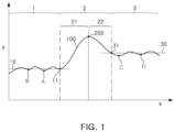
- the Sb average content line 30 of the base steel sheet 3 excluding the Sb-enriched layer may mean an extended line obtained by horizontally extending the Sb average content in a section from a point C spaced apart from the point (200: Sb max ) at which the content of Sb in the Sb-enriched layer 2 is the maximum value to the base steel sheet 3 by 15 ⁇ m to a point D spaced apart from Sb max by 20 ⁇ m.
- the Sb-enriched layer may be formed directly under the interface between the base steel sheet and the plating layer.
- the interface between the base steel sheet and the plating layer may be defined as a point at which a content of Al is 15%.
- a thickness of the enriched layer may be 1 to 30 ⁇ m.
- a content of antimony (Sb) when analyzed in the thickness direction of the base steel sheet using a glow discharge spectrometer (GDS), a content of carbon (C) at a depth at which a content of antimony (Sb) in the antimony (Sb)-enriched layer exhibits a maximum value (Sb max ) may be 10 to 70% of a nominal carbon content (C 0 ) of the base steel sheet.
- GDS glow discharge spectrometer
- the nominal carbon content (C 0 ) may mean a carbon average content in a region corresponding to 1/4 to 3/4 of the thickness based on a cross section of the base steel sheet, and specifically, may be an average carbon content obtained by analyzing a carbon profile at a distance of 50 ⁇ m or more from an arbitrary point in the region corresponding to 1/4 to 3/4 of the thickness of the base steel sheet using a glow discharge spectrometer (GDS).
- GDS glow discharge spectrometer
- FIG. 2 schematically illustrates content profiles of Sb and C in the thickness direction from the interface in the plated steel sheet according to an exemplary embodiment in the present disclosure.
- the X-axis may represent a depth ( ⁇ m) from the interface between the base steel sheet and the plating layer
- the Y-axis may represent a content (wt%) of element.
- 70% of the nominal carbon content (C 0 ) is 0.154%.
- the nominal carbon content (C 0 ) is 0.22%, which may be obtained by analyzing a certain thickness (depth) using a glow discharge spectrometer (GDS) in the region corresponding to 1/4 to 3/4 of the thickness of the base steel sheet as described above. In this case, it can be confirmed that the content of carbon at the depth at which the content of Sb shows the maximum value (Sb max ) exhibits a content of carbon of 70% or less of the nominal carbon content (C 0 ).
- GDS glow discharge spectrometer
- a ratio of the content of carbon to the nominal carbon content (C 0 ) is controlled to 10 to 70%, and in this case, the content of carbon affects a hardness softening rate of the surface layer and bendability of the part.
- the hardness of the surface layer part may increase, which may cause deterioration of the bendability.
- the content of carbon is less than 10% of the nominal carbon content (C 0 )
- the hardness decreases excessively, and thus, the fatigue resistance may be deteriorated.
- the ratio of the content of carbon to the nominal carbon content (C 0 ) may be 10.0 to 70.0%.
- a decarburization rate ( ⁇ ) of carbon (C) in a region from the interface between the base steel sheet and the plating layer to a depth of 30 ⁇ m in the thickness direction may be 14 to 35%.
- FIG. 3 schematically illustrates a decarburization rate ( ⁇ ) profile in the thickness direction from the interface in the plated steel sheet according to an exemplary embodiment in the present disclosure.
- the decarburization rate ( ⁇ ) may be obtained from the results of measuring carbon in the plated steel sheet using a glow discharge spectrometer (GDS).
- GDS glow discharge spectrometer
- the Y-axis represents a ratio of the content of carbon at the corresponding position to the nominal carbon content (C 0 )
- the X-axis represents a distance ( ⁇ m) in the thickness (depth) direction from the interface between the base steel sheet and the plating layer.
- a carbon profile curve indicating a ratio of a content of carbon at the corresponding depth to the nominal carbon content (C 0 ) is drawn, and a ratio (%) of an area above the carbon profile curve in the square to the entire area of the square may be defined as the decarburization rate ( ⁇ ).
- the decarburization rate ( ⁇ ) of the present disclosure means a ratio (%) of the area above the carbon profile curve to the entire area of the square in the square in which a horizontal axis represents the distance ( ⁇ m) in the thickness (depth) direction from the interface between the base steel sheet and the plating layer, and a vertical axis represents the ratio (%) of the content of carbon at the corresponding position to the nominal carbon content (C 0 ).
- the decarburization rate ( ⁇ ) of carbon (C) in the region from the interface to the depth of 30 ⁇ m in the thickness direction is less than 14%, a carbon enrichment degree in the base steel sheet may excessively increase the hardness in the part after hot press forming, and thus, the effect of improving bendability may be significantly reduced.
- the decarburization rate exceeds 35% the martensite hardness in the part may decrease significantly due to a decrease in the amount of carbon in the surface layer of the base steel sheet, which may cause deterioration of the fatigue resistance of the part.
- a decarburization rate ( ⁇ ) of carbon (C) in a region from the interface between the base steel sheet and the plating layer to a depth of 30.0 ⁇ m in the thickness direction may be 14.0 to 35.0%.
- a point at which a content of carbon (C) is 50% of the nominal carbon content (C 0 ) may exist at a depth of more than 1.5 ⁇ m and less than 6 ⁇ m from the interface between the base steel sheet and the plating layer in the thickness direction.
- Controlling the ratio of the content of carbon (C) to the nominal carbon content (C 0 ) at the depth of more than 1.5 ⁇ m and less than 6 ⁇ m from the interface in the thickness direction is to secure both the fatigue resistance and the impact resistance.
- a point at which the content of carbon (C) is 50% of the nominal carbon content (C 0 ) exists at the depth in the corresponding range it is advantageous for securing both the impact resistance and the fatigue resistance, but when the point of 50% exists at a depth of 6 ⁇ m or more, the fatigue resistance may be deteriorated due to excessive decarburization. Meanwhile, when the point of 50% exists at a depth of 1.5 ⁇ m or less, it may be difficult to secure the desired bendability due to insufficient decarburization.
- a point at which a content of carbon (C) is 50.0% of the nominal carbon content (C 0 ) may exist at a depth of more than 1.50 ⁇ m and less than 6.0 ⁇ m from the interface between the base steel sheet and the plating layer in the thickness direction.
- a point at which a content of carbon (C) is 80% of the nominal carbon content (C 0 ) may exist at a depth of more than 6 ⁇ m and less than 15 ⁇ m from the interface between the base steel sheet and the plating layer in the thickness direction.
- FIG. 4 schematically illustrates a profile of the Sb-enriched layer of the plated steel sheet according to an exemplary embodiment in the present disclosure.
- an area corresponding to the B value of Relational Expression 2 is indicated by the colored portion, and the area may indicate an Sb enriched degree according to ⁇ t, which represents the distance between the point where Sb coat is measured and the point where Sb max is measured.
- a region from the interface between the base steel sheet and the plating layer to a depth of 10.0 ⁇ m in the thickness direction may contain ferrite as a main phase and 1.0 area% or more of pearlite.
- the base steel sheet according to an exemplary embodiment in the present disclosure may contain, by wt%, 0.06 to 0.5% of carbon (C) and 0.01 to 0.1% of antimony.
- the base steel sheet according to an exemplary embodiment in the present disclosure may contain, by wt%, 0.060 to 0.50% of carbon (C) and 0.010 to 0.10% of antimony.
- % indicating a content of each element is based on weight.
- Carbon (C) is an element that increases strength of a hot press formed part and improves hardenability, and should be appropriately added as an essential element for controlling the strength.
- a content of carbon (C) is less than 0.06%, since the hardenability is low, when a cooling rate is reduced, sufficient martensite is not secured, and ferrite is formed, which may make it difficult to secure the desired strength.
- the content of carbon (C) may be 0.1% or more.
- an upper limit of the content of carbon (C) may be 0.45%.
- carbon (C) may be contained in an amount of 0.060 to 0.50%.
- carbon (C) may be 0.10% or more.
- the upper limit of carbon (C) may be 0.450%.
- Antimony (Sb) is enriched inside the base steel sheet, and may thus play a role in preventing an excessive decrease in hardness in the part by controlling the amount of carbon that escapes when internal oxidation annealing is applied.
- a content of antimony (Sb) is less than 0.01%, since a sufficient enriched layer is not formed at the interface between the plating layer and the base steel sheet, excessive decarburization occurs, which may cause an excessive decrease in hardness of the surface layer, resulting in deterioration of the fatigue resistance.
- a lower limit of antimony (Sb) may be 0.02%.
- an upper limit of the content of antimony (Sb) may be 0.08%.
- antimony (Sb) may be contained in an amount of 0.010 to 0.10%.
- antimony (Sb) may be 0.020% or more.
- the upper limit of antimony (Sb) may be 0.080%.
- the types and contents thereof are not limited as long as they are elements that may be generally added.
- the elements that may be added to the base steel sheet include silicon (Si), manganese (Mn), molybdenum (Mo), phosphorus (P), sulfur (S), aluminum (Al), chromium (Cr), nitrogen (N), titanium (Ti), boron (B), copper (Cu), nickel (Ni), vanadium (V), calcium (Ca), niobium (Nb), tin (Sn), tungsten (W), magnesium (Mg), cobalt (Co), arsenic (As), zirconium (Zr), bismuth (Bi), and a rare earth element (REM), and the base steel sheet may further contain one or more of these elements.
- the base steel sheet may contain, by wt%, 0.001 to 2% of silicon (Si), 0.1 to 4% of manganese (Mn), 1% or less of molybdenum (Mo), 0.05% or less of phosphorus (P), 0.02% or less of sulfur (S), 0.001 to 1% of aluminum (Al), 1.00% or less of chromium (Cr), 0.02% or less of nitrogen (N), 0.1% or less of titanium (Ti), 0.01% or less of boron (B), and a balance of iron (Fe) and impurities.
- Silicon (Si) may be added as a deoxidizer in steelmaking.
- silicon (Si) is a solid solution strengthening element and a carbide formation suppressing element, and is added as an element that is effective in internal structure uniformity, contributes to increasing the strength of the hot press formed part, and is effective in material uniformity.
- a content of silicon (Si) is less than 0.001%, the above effects are not expected, and when the content of silicon (Si) exceeds 2%, plating properties may be significantly deteriorated due to excessive Si oxides formed on the surface of the steel sheet during annealing.
- a lower limit of the content of silicon (Si) may be 0.005%, and may be 0.01% in some cases.
- an upper limit of the content of silicon (Si) may be 0.7%, and may be 0.65% in some cases.
- silicon (Si) may be contained in an amount of 0.001 to 2.0%.
- silicon (Si) may be 0.0050% or more.
- the upper limit of silicon (Si) may be 0.70%.
- silicon (Si) may be 0.010% or more.
- the upper limit of carbon (C) may be 0.650%.
- Manganese (Mn) needs to be added not only to secure the desired strength due to a solid solution strengthening effect thereof, but also to suppress the formation of ferrite during hot press forming through improvement of hardenability.
- a content of manganese (Mn) is less than 0.1%, it is difficult to obtain a sufficient hardenability effect and other expensive alloying elements are excessively required to compensate for the insufficient hardenability, and thus, manufacturing costs may increase significantly.
- manganese (Mn) may be contained in an amount of 0.5% or more, and as another exemplary embodiment, manganese (Mn) may be contained in an amount of 0.8% or more.
- an upper limit of the content of manganese (Mn) may be 3.5%.
- chromium (Cr) may be contained in an amount of 0.01 to 1.0%.
- chromium (Cr) may be contained in an amount of 0.05 to 1.0%.
- chromium (Cr) may be contained in an amount of 0.05 to 0.8%.
- Nitrogen (N) may be contained in the steel as an impurity.
- N When a content of nitrogen (N) exceeds 0.02%, N forms AlN with added Al, which may cause slab cracks. Meanwhile, a large amount of manufacturing costs may be required to control the content of nitrogen (N) to an extremely small amount, and thus, according to an exemplary embodiment in the present disclosure, a lower limit of nitrogen (N) may be limited to 0.001%.
- nitrogen (N) may be contained in an amount of 0.020% or less.
- nitrogen (N) may be contained in an amount of 0.0010 to 0.020%.
- titanium (Ti) may be contained in an amount of 0.10% or less.
- titanium (Ti) may be contained in an amount of 0.090% or less.
- Boron (B) is an element that may effectively improve hardenability, and is an element that is segregated at a prior austenite grain boundary and may thus suppress brittleness of the hot press formed part due to grain boundary segregation of P or S, which is an impurity. Meanwhile, when a content of boron (B) exceeds 0.01%, brittleness may be caused in hot rolling due to the formation of a Fe 23 CB 6 composite compound. In an exemplary embodiment in the present disclosure, an upper limit of the content of boron (B) may be limited to 0.008%.
- boron (B) may be contained in an amount of 0.010% or less.
- the base steel sheet may further contain one or more of 1% or less of copper (Cu), 1% or less of nickel (Ni), 1.0% or less of vanadium (V), 0.01% or less of calcium (Ca), 0.1% or less of niobium (Nb), 1% or less of tin (Sn), 1% or less of tungsten (W), 0.1% or less of magnesium (Mg), 1% or less of cobalt (Co), 1% or less of arsenic (As), 1% or less of zirconium (Zr), 1% or less of bismuth (Bi), and 0.3% or less of a rare earth element (REM).
- Cu copper
- Ni nickel
- V vanadium
- V vanadium
- Ca calcium
- Nb niobium
- Sn tin
- W tungsten
- Mg magnesium
- Co cobalt
- REM rare earth element
- the base steel sheet may further contain one or more of 1.0% or less of copper (Cu), 1.0% or less of nickel (Ni), 1.0% or less of vanadium (V), 0.010% or less of calcium (Ca), 0.10% or less of niobium (Nb), 1.0% or less of tin (Sn), 1.0% or less of tungsten (W), 0.10% or less of magnesium (Mg), 1.0% or less of cobalt (Co), 1.0% or less of arsenic (As), 1.0% or less of zirconium (Zr), 1.0% or less of bismuth (Bi), and 0.30% or less of a rare earth element (REM).
- Cu copper
- Ni nickel
- V vanadium
- Ca calcium
- Nb niobium
- Sn tin
- W tungsten
- Mg magnesium
- Co cobalt
- Ac arsenic
- Zr zirconium
- Bi bismuth
- REM rare earth element
- the base steel sheet of the present disclosure may contain a balance of iron (Fe) and unavoidable impurities in addition to the composition described above. Since the unavoidable impurities may be unintentionally incorporated in a general manufacturing process, the unavoidable impurities may not be excluded. Since these impurities are known to those skilled in a general steel manufacturing field, all the contents thereof are not particularly described in the present specification.
- the plating layer of the plated steel sheet may be an aluminum or aluminum-based alloy plating layer.
- the plating layer may be an alloyed aluminum-based plating layer.
- the plating layer may contain, in addition to Al, Si, Mg, and Fe, and may contain Mn, Cr, Cu, Mo, Ni, Sb, Sn, Ti, Ca, Sr, Zn, and the like in some cases.
- a thickness of the plating layer is not particularly limited, and the plating layer may have a thickness within a general range.
- the plating layer may contain, by wt%, one or two or more selected from 5 to 11% of Si, 5% or less of Fe, and 5% or less of Mg, and may contain a balance of Al and other impurities.
- the plating layer may further contain 30% or less of elements such as Mn, Cr, Cu, Mo, Ni, Sb, Sn, Ti, Ca, Sr, and Zn in total.
- the plating layer may contain, by wt%, one or two or more selected from 5.0 to 11.0% of Si, 5.0% or less of Fe, and 5.0% or less of Mg, and may contain a balance of Al and other impurities.
- the plating layer may further contain 30.0% or less of elements such as Mn, Cr, Cu, Mo, Ni, Sb, Sn, Ti, Ca, Sr, and Zn in total.
- a part according to an exemplary embodiment in the present disclosure may include a base steel and a plating layer formed on a surface of the base steel.
- the same alloy composition as that of the base steel sheet of the plated steel sheet suggested in the present disclosure may be applied to the base steel according to an aspect of the present disclosure.
- the plating layer may be formed on at least one surface of the base steel.
- the plating layer of the part may have an alloy composition in which components including Fe in the plating layer and the base steel sheet of the plated steel sheet described above are diffused.
- the part according to an exemplary embodiment in the present disclosure may include an antimony (Sb)-enriched layer in the base steel.
- the Sb-enriched layer of the present disclosure may be determined by analyzing a change in content of Sb from an arbitrary point of the plating layer in a thickness direction on a side of the base steel using a glow discharge spectrometer (GDS).
- GDS glow discharge spectrometer
- the method for determining the Sb-enriched layer in the plated steel sheet suggested in the present disclosure may be applied in the same manner.
- the antimony (Sb)-enriched layer may be formed directly under an interface where the base steel and the plating layer are in contact with each other.
- the interface between the base steel and the plating layer may mean a point at which a content of Al is 15%.
- a content of carbon (C) at a depth at which a content of antimony (Sb) in the antimony (Sb)-enriched layer exhibits a maximum value (Sb max ) may be 80% or less of a nominal carbon content (C 0 ) of the base steel.
- the content of carbon (C) at the depth at which the content of antimony (Sb) in the antimony (Sb)-enriched layer shows the maximum value (Sb max ) may be 80.0% or less of the nominal carbon content (C 0 ) of the base steel.
- the content of carbon at the depth at which the content of Sb in the Sb-enriched layer shows the maximum value (Sb max ) affects the hardness of the surface layer structure and affects the bendability. Meanwhile, when the content of carbon at the depth at which the content of Sb in the Sb-enriched layer shows the maximum value (Sb max ) exceeds 80% of the nominal carbon content (C 0 ), the hardness of the surface layer part may increase, which may cause deterioration of the bendability. However, when the content of carbon at the depth at which the content of Sb in the Sb-enriched layer shows the maximum value (Sb max ) is excessively low, the hardness of the surface layer part may be insufficient, which makes it difficult to secure fatigue resistance. Therefore, as an exemplary embodiment in the present disclosure, a lower limit thereof may be limited to 15%. As an exemplary embodiment in the present disclosure, the lower limit thereof may be limited to 15.0%.
- FIG. 5 schematically illustrates content profiles of Sb and C in the thickness direction from the interface in the part according to an exemplary embodiment in the present disclosure.
- the X-axis may represent a depth ( ⁇ m) from the interface between the base steel and the plating layer
- the Y-axis may represent a content (wt%) of element.
- 80% of the nominal carbon content (C 0 ) is 0.176%.
- the nominal carbon content (C 0 ) is 0.22%, which may be obtained by analyzing a certain thickness (depth) using a glow discharge spectrometer (GDS) in a region corresponding to 1/4 to 3/4 of the thickness of the base steel as described above. In this case, it can be confirmed that the content of carbon at the depth at which the content of Sb shows the maximum value exhibits a content of carbon of 80% or less of the nominal carbon content (C 0 ).
- GDS glow discharge spectrometer
- the part according to an exemplary embodiment in the present disclosure may have an R value defined in the following Relational Expression 1 of 1.5 or more and a B value defined in the following Relational Expression 2 of 0.01 or more.
- the part according to an exemplary embodiment in the present disclosure may have an R value defined in the following Relational Expression 1 of 1.50 or more and a B value defined in the following Relational Expression 2 of 0.010 or more.
- an Sb enrichment degree in the Sb-enriched layer may be more increased.
- the Sb-enriched layer serves to effectively block penetration of diffusible hydrogen, and the bendability may be increased by reducing diffusible hydrogen since diffusible hydrogen accelerates the occurrence of grain boundary cracks when stress occurs. That is, when the relational expressions are not satisfied, and specifically, when the R value defined in Relational Expression 1 is less than 1.5 or the B value defined in Relational Expression 2 is less than 0.01, during hot press forming, the penetration of diffusible hydrogen is not sufficiently blocked, and thus, the impact resistance may be deteriorated.
- the R value defined in Relational Expression 1 may be 1.7 or more.
- the B value defined in Relational Expression 2 may be 0.014 or more.
- an upper limit of the R value may be limited to 6.4.
- an upper limit of the B value may be limited to 0.5.
- the R value defined in Relational Expression 1 may be 1.70 or more.
- the B value defined in Relational Expression 2 may be 0.0140 or more.
- the upper limit of the R value may be limited to 6.40.
- an upper limit of the B value may be limited to 0.50.
- a softening rate ( ⁇ ) in a region from the interface between the base steel and the plating layer to a depth of 45 to 100 ⁇ m in the thickness direction may be 2 to 7%.
- the region from the interface between the base steel and the plating layer to the depth of 45 to 100 ⁇ m in the thickness direction may affect the hardness of the surface layer part of the part, and may affect the bendability.
- the softening rate in a region to a depth of 45 to 100 ⁇ m in the thickness direction is less than 2%, the hardness of the surface layer part increases excessively, and thus, the effect of improving bendability may be reduced.
- the softening rate exceeds 7% the hardness of the surface layer part decreases excessively, and thus, the fatigue resistance may be deteriorated.
- the hardness softening rate may be measured as illustrated in FIG. 6.
- FIG. 6 schematically illustrates a hardness softening rate ( ⁇ ) profile at a depth of 45 to 100 ⁇ m in the thickness direction from the interface in the part according to an exemplary embodiment in the present disclosure. Specifically, a Vickers hardness is measured and the hardness is measured by applying a weight of 1 kg. The hardness inside the base steel is set as a reference hardness (H O ), and the reference hardness (H O ) may be measured at a point of 1/5 of the thickness of the base steel.
- H O reference hardness
- the Y-axis represents a ratio (%) of a hardness value (H) at the corresponding position to the reference hardness value (H O ), and the X-axis represents a distance ( ⁇ m) from the interface in the thickness direction.
- a square is drawn with 0 to 100% as the Y-axis range and a depth of 45 to 100 ⁇ m from the interface as the X-axis range.
- a hardness profile curve indicating a ratio of hardness values according to the depth from the interface in the square may be indicated, and a ratio of an area of an upper region in the square of the hardness profile to the entire area of the square may be defined as the hardness softening rate ( ⁇ , %).
- a hardness profile is created at a depth of 45 to 100 ⁇ m and used for the hardness softening rate ( ⁇ ).
- the hardness softening rate ( ⁇ ) of the present disclosure means a ratio (%) of the area above the hardness profile curve to the entire area of the square in the square in which a horizontal axis represents the distance ( ⁇ m) from the interface between the base steel sheet and the plating layer in the thickness (depth) direction, and a vertical axis represents the ratio (%) of the hardness value (H) at the corresponding position to the reference hardness (H O ).
- a softening rate ( ⁇ ) in a region from an interface between the base steel and the plating layer to a depth of 45.0 to 100.0 ⁇ m in the thickness direction may be 2.0 to 7.0%.
- the ferrite in the region from the interface between the base steel and the plating layer to the depth of 50 ⁇ m in the thickness direction may cause propagation of cracks. That is, in a case where the ferrite is 5% or more in the corresponding region, when stress occurs in the surface layer part, the stress is locally concentrated on the relatively soft ferrite, and the propagation of cracks is accelerated, which may cause deterioration of the bendability and the fatigue resistance.
- the physical properties desired in the present disclosure may be insufficient.
- a region from the interface between the base steel and the plating layer to a depth of 50.0 ⁇ m in the thickness direction may have a microstructure containing less than 5.0 area% of ferrite.
- the part according to an exemplary embodiment in the present disclosure may have a microstructure containing martensite as a main phase in a region from the interface between the base steel and the plating layer to a depth of 50.0 ⁇ m in the thickness direction, less than 5.0 area% of ferrite, and a balance of upper and lower bainite.
- a phase having an area fraction of 50.0% or more of the total microstructure fraction may be regarded as the main phase.
- the plated steel sheet according to an aspect of the present disclosure may be manufactured by annealing and plating a cold-rolled steel sheet satisfying the alloy composition described above.
- the cold-rolled steel sheet may be manufactured by reheating, hot rolling, coiling, cooling, and cold rolling a steel slab satisfying the alloy composition described above.
- the reheating temperature is lower than 1,050°C, a slab structure is not sufficiently homogenized, and thus, when precipitated elements are used, it is difficult to solid-dissolve these elements again.
- the temperature exceeds 1,300°C, an oxide layer is excessively formed, which may cause an increase in manufacturing costs for removing the oxide layer and the occurrence of surface defects occurring after hot rolling.
- the reheated steel slab may be finish rolled in a temperature range of 800 to 950°C.
- finish rolling temperature is lower than 800°C, two-phase region rolling is performed, and ferrite is introduced into the surface layer part of the steel sheet, which may make it difficult to control a sheet shape.
- the temperature exceeds 950°C, coarsening of grains may occur.
- the rolled steel may be coiled and cooled in a temperature range of 500 to 700°C.
- a cold-rolled steel sheet may be manufactured by cold rolling the cooled steel at a reduction ratio of 30 to 80%.
- the reduction ratio is not particularly limited, and cold rolling may be performed at a reduction ratio of 30 to 80% to obtain a predetermined target thickness.
- the cold-rolled steel sheet may be annealed in a temperature range of Ac 1 to Ac 3 .
- a lower limit of the annealing temperature may be 750°C.
- an upper limit of the annealing temperature may be limited to 860°C.
- a product of an annealing time and an absolute humidity may be 10,000 to 80,000 s ⁇ g/m 3 .
- the atmosphere and humidity may be controlled by using hydrogen gas, hydrogen-nitrogen mixed gas, and the like to form an oxidizing atmosphere, and it is important to control the annealing time and the absolute humidity in the temperature range of Ac 1 to Ac 3 to obtain an appropriate decarburization rate of the steel sheet.
- the product of the annealing time and the absolute humidity may be 10,000 to 80,000 s ⁇ g/m 3 .
- the annealing time may be 100 to 200 seconds.
- the absolute humidity may be 100 to 400 g/m 3 .
- an average temperature increase rate from room temperature to 500°C may be controlled to 2.7 to 10.0°C/s
- an average temperature increase rate in a section of 500 to 700°C may be controlled to 0.5 to 2.5°C/s
- an average temperature increase rate from 700°C to the annealing temperature may be controlled to 0.01 to 0.4°C/s.
- the average temperature increase rate from room temperature to 500°C is limited to 2.7 to 10.0°C/s to secure an Sb-enriched layer.
- the average temperature increase rate from room temperature to 500°C is outside of the range of 2.7 to 10.0°C/s, specifically, when the average temperature increase rate is less than 2.7°C/s, an enriched layer is not sufficiently formed, and when the average temperature increase rate exceeds 10°C/s, temperature unevenness in a width direction of the steel sheet increases due to rapid heating, which may cause differences in structure and line trouble.
- the Sb enrichment of the base steel may be affected.
- the Sb-enriched layer may not be sufficiently formed.
- the temperature of the surface of the steel sheet from 700°C to the desired annealing temperature is a temperature at which an Sb-enriched layer is sufficiently formed in the base steel, and it is preferable that the average temperature increase rate is 0.01 to 0.4°C/s in order to prevent defects of the Sb-enriched layer satisfying Relational Expressions 1 and 2 and the surface part of the steel sheet.
- the annealed cold-rolled steel sheet may be plated.
- a plating bath according to an aspect of the present disclosure may be formed of aluminum or an aluminum-based alloy.
- the composition of the plating bath may contain, in addition to Al, Si, Mg, and Fe, and may contain Mn, Cr, Cu, Mo, Ni, Sb, Sn, Ti, Ca, Sr, Zn, and the like in some cases.
- a coating amount is not particularly limited, and may be a coating amount in a general range.
- the composition of the plating bath may contain, by wt%, one or two or more selected from 5 to 11% of Si, 5% or less of Fe, and 5% or less of Mg, and may contain a balance of Al and other impurities.
- an alloying process may be included after plating, and the alloying process is not particularly limited and may be performed under general conditions.
- the part according to an aspect of the present disclosure may be manufactured by manufacturing a blank using a plated steel sheet to be manufactured by the method described, and heating, maintaining, forming, and cooling the blank.
- the heated blank has a heat treatment residence time of 10 to 1,000 seconds in the above temperature range.
- the maintenance time is shorter than 10 seconds, it is difficult to uniformly distribute the temperature throughout the blank, which may cause a material variation for each position.
- the plated steel sheet of the present disclosure manufactured as described above may maintain the hardness of the surface layer at a certain level or lower, and may maintain a blade lifespan at a certain level or lower when shearing is performed to manufacture a blank for hot press forming, thereby having the effect of reducing the costs consumed.
- the part of the present disclosure manufactured as described above may have excellent fatigue resistance and bendability with a product of a tensile strength and a bending angle of 80,000 MPa ⁇ ° or more and the amount of diffusible hydrogen of 0.2 ppm or less.
- tensile strength (TS)*bending angle (BA) is used as an index to measure the impact resistance.
- the bending angle which is an index of the impact resistance, is affected by the tensile strength and has an inversely proportional tendency. Therefore, as the value of the product of the tensile strength and the bending angle (TS*BA) increases, the impact resistance increases.
- the BA value may be measured through a bendability evaluation according to the VDA238-100 standard and is expressed as a bending outer angle converted from a maximum bending strength.
- Slabs containing Sb in the contents disclosed in Table 1 and having a composition of 0.22C-0.25Si-1.25Mn-0.2Cr-0.03Al-0.03Ti-0.0025B and a thickness of 40 mm were manufactured by vacuum dissolving.
- the slabs were heated to 1,200°C and maintained for 1 hour, the heated slabs were hot-rolled at a hot rolling end temperature of 900°C, and then the hot-rolled slabs were coiled at a temperature of 600°C. Thereafter, a pickling process was performed, and cold rolling was performed at a reduction ratio of 30 to 80%, thereby manufacturing cold-rolled steel sheets.
- the cold-rolled steel sheets were annealed at a temperature of Ac 1 to Ac 3 , an annealing time (s) and an absolute humidity (g/m 3 ) were controlled, and values of a product of the annealing time and the absolute humidity were shown in Table 1.
- plating was performed by immersing the steel sheets in a plating bath formed of Al-9%Si-2%Fe and trace impurities. [Table 1] Specimen Nos.
- Annealing Sb (wt%) Annealing time ⁇ absolute humidity (s ⁇ g/m 3 ) Steel sheet surface average temperature increase rate (°C/s) Room temperature to 500°C 500 to 700°C 700°C to annealing temperature 1 0.072 10,654 2.9 2.0 0.03 2 0.045 22,347 6.7 1.6 0.10 3 0.036 40,451 4.5 1.0 0.16 4 0.015 58,363 9.
- Table 2 shows the results of measuring an Sb-enriched layer, a microstructure, and a decarburization rate of each of the manufactured plated steel sheets.
- an area fraction of pearlite was measured by observing the structure directly under an interface using scanning electron microscopy (SEM). At this time, in all the specimens, the residual fraction excluding the area fraction of pearlite was observed as ferrite.
- a part was manufactured by hot press forming using a plated steel sheet in which a non-plated area was not observed.
- a heat treatment temperature and time for hot press forming were 900°C and 360 seconds, and a transfer time from a heat treatment furnace to a forming press was set to 10 seconds.
- Table 3 shows the structure and properties of the parts manufactured through the hot press forming were measured by the same method as described above.
- a Vickers hardness was measured by applying a load of 1.0 kg in a region from the interface between the plating layer and the base steel of the part to a depth of 45 to 100 ⁇ m, and a hardness softening rate ( ⁇ ) was shown using FIG. 6 and the method described above.
- the amount of diffusible hydrogen was measured using a thermal desorption analysis (TDA) equipment (Bruker G8, model name). Specifically, the temperature was increased to 400°C at 20°C/min and maintained for a certain time so that a diffusible hydrogen peak sufficiently appeared to measure a diffusible hydrogen curve, and the curve was integrated to obtain the amount of diffusible hydrogen in the steel.
- TDA thermal desorption analysis
- a ferrite area fraction in a range from the interface between the base steel and the plating layer to a depth of 30 ⁇ m was measured using optical microscopy and was shown in Table 3. At this time, in all the specimens, the residual fraction excluding the ferrite area fraction was observed as martensite.
- the fatigue limit strength was measured by repeatedly performing a fatigue test 10,000,000 times or more by applying the JIS Z2275 standard, a case in which the value of the fatigue limit strength obtained by dividing the fatigue limit strength by the tensile strength was 0.25 or more was marked as O, and a case in which the value of the fatigue limit strength was less than 0.025 was marked as X.
- the impact resistance was expressed as the product of the tensile strength and the bending angle, and the tensile strength value was measured through a tensile test at room temperature using a JIS-5 specimen according to the ISO6892 standard.
- the bending angle was expressed as the bending outer angle converted from the maximum bending strength specified in the standard according to the bendability evaluation method of the VDA238-100 standard. [Table 3] Specime n Nos.
- FIG. 7 illustrates a carbon profile in the plated steel sheet according to an exemplary embodiment in the present disclosure.
- the decarburization control suggested in the present disclosure was sufficiently achieved, and as a result, the product of the tensile strength and the bending angle and the fatigue resistance at certain levels or higher were secured.
- Comparative Example 1 the decarburization was not sufficiently achieved according to the depth, and in Comparative Example 3, excessive decarburization occurred due to insufficient formation of the Sb-enriched layer, and thus, the physical properties were deteriorated.
- FIG. 8 illustrates photographs of the structures directly under the interfaces in the plated steel sheets of Inventive Example 3 and Comparative Example 3 according to an exemplary embodiment in the present disclosure observed with SEM. It was confirmed that, in Inventive Example 3, 2.9% of pearlite was observed, and in Comparative Example 3, less than 1% of pearlite was observed.
- FIG. 9 illustrates optical photographs of the interfaces between the plating layers and the base steels in the parts of Inventive Example 3 and Comparative Example 3 of the present disclosure.
- Inventive Example 3 less than 1% of ferrite was observed, but in Comparative Example 3, ferrite was 7.3%, and thus, the fatigue resistance desired in the present disclosure was not secured.
Landscapes
- Chemical & Material Sciences (AREA)
- Engineering & Computer Science (AREA)
- Mechanical Engineering (AREA)
- Organic Chemistry (AREA)
- Materials Engineering (AREA)
- Metallurgy (AREA)
- Physics & Mathematics (AREA)
- Thermal Sciences (AREA)
- Crystallography & Structural Chemistry (AREA)
- Chemical Kinetics & Catalysis (AREA)
- Oil, Petroleum & Natural Gas (AREA)
- Heat Treatment Of Sheet Steel (AREA)
- Coating With Molten Metal (AREA)
- Heat Treatment Of Articles (AREA)
- Shaping Metal By Deep-Drawing, Or The Like (AREA)
Abstract
Description
- The present disclosure relates to a plated steel sheet for hot press forming, a hot press formed part, and manufacturing methods thereof, and in particular, to a plated steel sheet for hot press forming having excellent impact resistance, a hot press formed part, and manufacturing methods thereof.
- Recently, a hot press formed part has mainly been applied to an automobile structural part to achieve improvement of fuel efficiency, protection of passengers, and the like through weight reduction of an automobile, and particularly, may be used for a bumper, a door, a pillar reinforcement, or the like that requires ultra-high strength or high energy absorption capacity.
-
Patent Document 1 was suggested as a representative technology regarding the hot press forming technology. In the patent, an Al-Si plated steel sheet is heated to 850°C or higher, and then hot press forming and quenching by a press are performed to form a structure of a part with martensite, such that ultra-high strength with high tensile strength may be secured. In a case in which such ultra-high strength steel for hot press forming is applied, a complex shape may be easily formed because the formation is performed at high temperature, and a weight reduction effect may be expected through an increase in strength by quenching in a mold. - However, along therewith, automobile manufacturers are increasingly required to improve impact resistance for passenger safety, but conventional steel for hot press forming has a martensite structure, which provides high strength but poor impact resistance in the case of collisions, and thus requires improvement.
- (Patent Document 1)
U.S. Patent No. 6,296,805 (published on October 2, 2001 ) - An aspect of the present disclosure is to provide a plated steel sheet for hot press forming having excellent impact resistance, a hot press formed part, and manufacturing methods thereof.
- An object of the present disclosure is not limited to the above description. Those skilled in the art will have no difficulties in understanding the additional objects of the present disclosure from the overall descriptions of the present specification.
- According to an aspect of the present disclosure, a plated steel sheet includes a base steel sheet containing, by wt%, 0.06 to 0.5% of carbon (C) and 0.01 to 0.1% of antimony (Sb) and a plating layer formed on a surface of the base steel sheet,
- wherein the base steel sheet includes an antimony (Sb)-enriched layer therein, and
- when contents of elements are analyzed in a thickness direction of the base steel sheet using a glow discharge spectrometer, a content of carbon (C) at a depth at which a content of antimony (Sb) in the antimony (Sb)-enriched layer exhibits a maximum value (Sbmax) is 10 to 70% of a nominal carbon content (C0) of the base steel sheet.
- A decarburization rate (α) of carbon (C) in a region from an interface between the base steel sheet and the plating layer to a depth of 30 µm in the thickness direction may be 14 to 35%.
- In the plated steel sheet, a point at which a content of carbon (C) is 50% of the nominal carbon content (C0) may exist at a depth of more than 1.5 µm and less than 6 µm from an interface between the base steel sheet and the plating layer in the thickness direction.
- In the plated steel sheet, a point at which a content of carbon (C) is 80% of the nominal carbon content (C0) may exist at a depth of more than 6 µm and less than 15 µm from an interface between the base steel sheet and the plating layer in the thickness direction.
- The plated steel sheet may have an R value defined in the following
Relational Expression 1 of 1.2 or more, and - a B value defined in the following
Relational Expression 2 of 0.008 or more:


- (wherein Sbmax represents a maximum value of the content of Sb in the Sb-enriched layer, Sbcoat represents an average Sb content in the plating layer, and units thereof are wt%, and Δt represents a straight distance between an interface between the plating layer and the base steel sheet and a point at which Sbmax is measured, and a unit thereof is µm).
- A region from an interface between the base steel sheet and the plating layer to a depth of 10 µm in the thickness direction may have a microstructure containing ferrite as a main phase and 1 area% or more of pearlite.
- The base steel sheet may contain 0.06 to 0.5% of carbon (C), 0.01 to 0.1% of antimony (Sb), 0.001 to 2% of silicon (Si), 0.1 to 4% of manganese (Mn), 1% or less of molybdenum (Mo), 0.05% or less of phosphorus (P), 0.02% or less of sulfur (S), 0.001 to 1% of aluminum (Al), 1% or less of chromium (Cr), 0.02% or less of nitrogen (N), 0.1% or less of titanium (Ti), 0.01% or less of boron (B), and a balance of iron (Fe) and impurities.
- The plating layer may be formed of aluminum or an aluminum alloy.
- According to another aspect of the present disclosure, a part includes a base steel containing, by wt%, 0.06 to 0.5% of carbon (C) and 0.01 to 0.1% of antimony and a plating layer formed on a surface of the base steel,
- wherein the base steel includes an antimony (Sb)-enriched layer therein, and
- when contents of elements are analyzed in a thickness direction of the base steel using a glow discharge spectrometer, a content of carbon (C) at a depth at which a content of antimony (Sb) in the antimony (Sb)-enriched layer exhibits a maximum value (Sbmax) is 80% or less of a nominal carbon content (C0) of the base steel.
- In the part, the content of carbon (C) at the depth at which the content of antimony (Sb) shows the maximum value (Sbmax) may be 15 to 80% of the nominal carbon content (C0) of the base steel.
- The part may have an R value defined in the following
Relational Expression 1 of 1.5 or more, and - a B value defined in the following
Relational Expression 2 of 0.01 or more:


- (wherein Sbmax represents a maximum value of the content of Sb in the Sb-enriched layer, Sbcoat represents an average Sb content in the plating layer, and units thereof are wt%, and Δt represents a straight distance between an interface where the plating layer and the base steel are in contact with each other and a point at which Sbmax is measured, and a unit thereof is µm).
- A softening rate (β) in a region from an interface between the base steel and the plating layer to a depth of 45 to 100 µm in the thickness direction may be 2 to 7%.
- A region from an interface between the base steel and the plating layer to a depth of 50 µm in the thickness direction may have a microstructure containing less than 5 area% of ferrite.
- A region from an interface between the base steel and the plating layer to a depth of 50 µm in the thickness direction may have a microstructure containing martensite as a main phase, less than 5 area% of ferrite, and a balance of upper and lower bainite.
- The base steel may contain 0.06 to 0.5% of carbon (C), 0.01 to 0.1% of antimony (Sb), 0.001 to 2% of silicon (Si), 0.1 to 4% of manganese (Mn), 1% or less of molybdenum (Mo), 0.05% or less of phosphorus (P), 0.02% or less of sulfur (S), 0.001 to 1% of aluminum (Al), 1% or less of chromium (Cr), 0.02% or less of nitrogen (N), 0.1% or less of titanium (Ti), 0.01% or less of boron (B), and a balance of iron (Fe) and impurities.
- The plating layer may be formed of aluminum or an aluminum alloy.
- The part may have a product of a tensile strength and a bending angle of 80,000 MPa·° or more.
- The amount of diffusible hydrogen in the part may be 0.2 ppm or less.
- According to still another aspect of the present disclosure, a manufacturing method of a plated steel sheet includes: preparing a cold-rolled steel sheet containing, by wt%, 0.06 to 0.5% of carbon (C) and 0.01 to 0.1% of antimony;
- annealing the cold-rolled steel sheet in a temperature range of Ac1 to Ac3; and
- plating the annealed cold-rolled steel sheet,
- wherein during the annealing, a product of an annealing time and an absolute humidity is 10,000 to 80,000 s·g/m3, and
- during the annealing, based on a surface temperature of the steel sheet, an average temperature increase rate from room temperature to 500°C is 2.7 to 10.0°C/s, an average temperature increase rate in a section of 500 to 700°C is 0.5 to 2.5°C/s, and an average temperature increase rate from 700°C to an annealing temperature is 0.01 to 0.4°C/s.
- During the annealing, the annealing time may be 100 to 200 seconds, and the absolute humidity may be 100 to 400 g/m3.
- The cold-rolled steel sheet may be manufactured by:
- reheating a steel slab to a temperature range of 1,050 to 1,300°C;
- finish rolling the reheated steel slab in a temperature range of 800 to 950°C;
- coiling and cooling the rolled steel in a temperature range of 500 to 700°C; and
- cold rolling the cooled steel at a reduction ratio of 30 to 80%.
- The steel slab may contain 0.06 to 0.5% of carbon (C), 0.01 to 0.1% of antimony (Sb), 0.001 to 2% of silicon (Si), 0.1 to 4% of manganese (Mn), 1% or less of molybdenum (Mo), 0.05% or less of phosphorus (P), 0.02% or less of sulfur (S), 0.001 to 1% of aluminum (Al), 1% or less of chromium (Cr), 0.02% or less of nitrogen (N), 0.1% or less of titanium (Ti), 0.01% or less of boron (B), and a balance of iron (Fe) and impurities.
- During the plating, the plating may be performed with aluminum or an aluminum alloy.
- According to still another aspect of the present disclosure, a manufacturing method of a part includes: manufacturing a blank using any one of the plated steel sheets;
- heating the blank to a temperature range of Ac3 to 975°C and maintaining the blank for 10 to 1,000 seconds; and
- forming and cooling the heated blank.
- During the cooling, the cooling may be performed at a cooling rate of 20°C/s or more.
- According to an aspect of the present disclosure, it is possible to provide a plated steel sheet for hot press forming having excellent impact resistance, a hot press formed part, and manufacturing methods thereof.
- According to an aspect of the present disclosure, it is possible to provide a plated steel sheet for hot press forming having excellent fatigue resistance and impact resistance, a hot press formed part, and manufacturing methods thereof.
-
-
FIG. 1 schematically illustrates an exemplary change in content of Sb of the present disclosure to show an Sb-enriched layer. -
FIG. 2 schematically illustrates content profiles of Sb and C in a thickness direction from an interface in a plated steel sheet according to an exemplary embodiment in the present disclosure. -
FIG. 3 schematically illustrates a decarburization rate (α) profile in the thickness direction from the interface in the plated steel sheet according to an exemplary embodiment in the present disclosure. -
FIG. 4 schematically illustrates a profile of an Sb-enriched layer of the plated steel sheet according to an exemplary embodiment in the present disclosure. -
FIG. 5 schematically illustrates content profiles of Sb and C in a thickness direction from an interface in a part according to an exemplary embodiment in the present disclosure. -
FIG. 6 schematically illustrates a hardness softening rate (β) profile in the thickness direction from the interface in the part according to an exemplary embodiment in the present disclosure. -
FIG. 7 illustrates a content profile of C in the plated steel sheet according to an exemplary embodiment in the present disclosure. -
FIG. 8 is a photograph of a microstructure of the plated steel sheet according to an exemplary embodiment in the present disclosure observed with scanning electron microscopy (SEM). -
FIG. 9 is a photograph obtained by observing a microstructure of the part according to an exemplary embodiment in the present disclosure. - Hereinafter, preferred exemplary embodiments in the present disclosure will be described. The exemplary embodiments in the present disclosure may be modified in various forms, and the scope of the present disclosure should not be interpreted to be limited to the exemplary embodiments set forth below. The exemplary embodiments are provided in order to describe the present disclosure in more detail to those skilled in the art to which the present disclosure pertains.
- In order to solve the problems of the related art, a measure to improve bendability by applying a decarburization technology may be considered, but fatigue characteristics may be deteriorated due to a local decrease in hardness of a surface layer part, which may limit the applications to automobile parts. Therefore, as a result of conducting intensive studies to solve these problems, the inventors of the present disclosure have found that when an antimony (Sb)-enriched layer is formed on a base steel sheet and a decarburization rate of the steel sheet is maintained at an appropriate level, the problem of deterioration of fatigue characteristics may be solved and the impact resistance may also be improved, thereby completing the present disclosure.
- Hereinafter, the present disclosure will be described in more detail.
- An aspect of the present disclosure relates to a plated steel sheet including a base steel sheet and a plating layer formed on a surface of the base steel sheet. The impact resistance and fatigue resistance may be greatly affected by a degree of decarburization of the steel sheet, and when a decarburization rate is appropriately controlled by using an enriched layer formed in the base steel sheet, the effects of the present disclosure may be advantageously obtained. That is, the plated steel sheet according to an aspect of the present disclosure may include a base steel sheet and a plating layer formed on a surface (may mean an interface between the base steel sheet and the plating layer) of the base steel sheet, and the base steel sheet may include an antimony (Sb)-enriched layer therein.
- According to an exemplary embodiment in the present disclosure, when an antimony (Sb)-enriched layer is formed in the steel sheet, a decarburization rate according to a depth of the steel sheet in a thickness direction may be appropriately controlled by the formation of the Sb-enriched layer.
- Hereinafter, an Sb-enriched layer and its role according to an exemplary embodiment in the present disclosure will be described in detail with reference to the graph of
FIG. 1. FIG. 1 schematically illustrates an exemplary change in content of Sb of the present disclosure to show the Sb-enriched layer, and inFIG. 1 , the X-axis represents a straight distance from the plating layer in a direction toward the base steel sheet, that is, in a thickness direction, at an arbitrary location in the plated steel sheet, and the Y-axis represents a content of Sb measured using a glow discharge spectrometer (GDS).FIG. 1 illustrates changes in contents of Sb in aplating layer 1, an Sb-enrichedlayer 2, and abase steel sheet 3 excluding the Sb-enrichedlayer 2. Here, the Sb-enrichedlayer 2 may have a content of Sb of 1.05 times or more the nominal Sb content (Sb0) of the base steel sheet, and a point (200: Sbmax) at which the content of Sb is a maximum value may exist in the Sb-enrichedlayer 2. In addition, the Sb-enrichedlayer 2 may include an Sbcontent increasing section 21 in which the content of Sb increases to the point (200: Sbmax) at which the content of Sb is the maximum value in the X-axis direction, and an Sbcontent decreasing section 22 in which the content of Sb decreases from the point (200: Sbmax) at which the content of Sb is the maximum value in the X-axis direction. InFIG. 1 , a final contact point 11 of an Sbaverage content line 10 of theplating layer 1 and theSb content line 100 before reaching the point (200: Sbmax) at which the content of Sb is the maximum value in an X-axis (+) direction may be set as a starting point of the Sbcontent increasing section 21. - In an exemplary embodiment, the Sb
average content line 10 of theplating layer 1 may mean an extended line obtained by horizontally extending the Sb average content in a section from a point A spaced apart from the point (200: Sbmax) at which the content of Sb in the Sb-enrichedlayer 2 is the maximum value to theplating layer 1 by 15 µm to a point B spaced apart from Sbmax by 20 µm. - In the same manner, in the Sb
content decreasing section 22 from the point (200: Sbmax) at which the content of Sb is the maximum value in the X-axis (+) direction, aninitial contact point 31 of an Sbaverage content line 30 of the base steel sheet and theSb content line 100 in the X-axis (+) direction is regarded as an end point of the Sb-enrichedlayer 2. - In an exemplary embodiment, the Sb
average content line 30 of thebase steel sheet 3 excluding the Sb-enriched layer may mean an extended line obtained by horizontally extending the Sb average content in a section from a point C spaced apart from the point (200: Sbmax) at which the content of Sb in the Sb-enrichedlayer 2 is the maximum value to thebase steel sheet 3 by 15 µm to a point D spaced apart from Sbmax by 20 µm. - In an exemplary embodiment in the present disclosure, the Sb-enriched layer may be formed directly under the interface between the base steel sheet and the plating layer. For example, when a content profile of Al is analyzed in the depth (thickness) direction from the surface of the plated steel sheet using a glow discharge spectrometer (GDS), the interface between the base steel sheet and the plating layer may be defined as a point at which a content of Al is 15%. In addition, for example, a thickness of the enriched layer may be 1 to 30 µm.
- In addition, according to an exemplary embodiment in the present disclosure, when a content of antimony (Sb) is analyzed in the thickness direction of the base steel sheet using a glow discharge spectrometer (GDS), a content of carbon (C) at a depth at which a content of antimony (Sb) in the antimony (Sb)-enriched layer exhibits a maximum value (Sbmax) may be 10 to 70% of a nominal carbon content (C0) of the base steel sheet. In an exemplary embodiment in the present disclosure, the nominal carbon content (C0) may mean a carbon average content in a region corresponding to 1/4 to 3/4 of the thickness based on a cross section of the base steel sheet, and specifically, may be an average carbon content obtained by analyzing a carbon profile at a distance of 50 µm or more from an arbitrary point in the region corresponding to 1/4 to 3/4 of the thickness of the base steel sheet using a glow discharge spectrometer (GDS).
-
FIG. 2 schematically illustrates content profiles of Sb and C in the thickness direction from the interface in the plated steel sheet according to an exemplary embodiment in the present disclosure. InFIG. 2 , the X-axis may represent a depth (µm) from the interface between the base steel sheet and the plating layer, and the Y-axis may represent a content (wt%) of element. As illustrated inFIG. 2 , 70% of the nominal carbon content (C0) is 0.154%. Here, the nominal carbon content (C0) is 0.22%, which may be obtained by analyzing a certain thickness (depth) using a glow discharge spectrometer (GDS) in the region corresponding to 1/4 to 3/4 of the thickness of the base steel sheet as described above. In this case, it can be confirmed that the content of carbon at the depth at which the content of Sb shows the maximum value (Sbmax) exhibits a content of carbon of 70% or less of the nominal carbon content (C0). - As illustrated in
FIG. 2 , in an exemplary embodiment in the present disclosure, at the depth at which the content of Sb in the Sb-enriched layer shows the maximum value (Sbmax), a ratio of the content of carbon to the nominal carbon content (C0) is controlled to 10 to 70%, and in this case, the content of carbon affects a hardness softening rate of the surface layer and bendability of the part. - Meanwhile, when the content of carbon at the depth at which the content of Sb in the Sb-enriched layer shows the maximum value (Sbmax) exceeds 70% of the nominal carbon content (C0), the hardness of the surface layer part may increase, which may cause deterioration of the bendability. In addition, according to an exemplary embodiment in the present disclosure, when the content of carbon is less than 10% of the nominal carbon content (C0), the hardness decreases excessively, and thus, the fatigue resistance may be deteriorated.
- In an exemplary embodiment in the present disclosure, at the depth at which the content of Sb in the Sb-enriched layer shows the maximum value (Sbmax), the ratio of the content of carbon to the nominal carbon content (C0) may be 10.0 to 70.0%.
- According to an exemplary embodiment in the present disclosure, a decarburization rate (α) of carbon (C) in a region from the interface between the base steel sheet and the plating layer to a depth of 30 µm in the thickness direction may be 14 to 35%.
-
FIG. 3 schematically illustrates a decarburization rate (α) profile in the thickness direction from the interface in the plated steel sheet according to an exemplary embodiment in the present disclosure. InFIG. 3 , the decarburization rate (α) may be obtained from the results of measuring carbon in the plated steel sheet using a glow discharge spectrometer (GDS). In the drawing, the Y-axis represents a ratio of the content of carbon at the corresponding position to the nominal carbon content (C0), and the X-axis represents a distance (µm) in the thickness (depth) direction from the interface between the base steel sheet and the plating layer. As illustrated in the drawing, it is possible to draw a square having a horizontal side corresponding to a depth of 0 to 30 µm in the thickness direction of the base steel sheet from the interface in the X-axis direction and a vertical side corresponding to a length of 0 to 100% in the Y-axis direction. Here, in the square, a carbon profile curve indicating a ratio of a content of carbon at the corresponding depth to the nominal carbon content (C0) is drawn, and a ratio (%) of an area above the carbon profile curve in the square to the entire area of the square may be defined as the decarburization rate (α). - In other words, the decarburization rate (α) of the present disclosure means a ratio (%) of the area above the carbon profile curve to the entire area of the square in the square in which a horizontal axis represents the distance (µm) in the thickness (depth) direction from the interface between the base steel sheet and the plating layer, and a vertical axis represents the ratio (%) of the content of carbon at the corresponding position to the nominal carbon content (C0).
- When the decarburization rate (α) of carbon (C) in the region from the interface to the depth of 30 µm in the thickness direction is less than 14%, a carbon enrichment degree in the base steel sheet may excessively increase the hardness in the part after hot press forming, and thus, the effect of improving bendability may be significantly reduced. On the other hand, when the decarburization rate exceeds 35%, the martensite hardness in the part may decrease significantly due to a decrease in the amount of carbon in the surface layer of the base steel sheet, which may cause deterioration of the fatigue resistance of the part.
- According to an exemplary embodiment in the present disclosure, a decarburization rate (α) of carbon (C) in a region from the interface between the base steel sheet and the plating layer to a depth of 30.0 µm in the thickness direction may be 14.0 to 35.0%.
- In the plated steel sheet according to another exemplary embodiment in the present disclosure, a point at which a content of carbon (C) is 50% of the nominal carbon content (C0) may exist at a depth of more than 1.5 µm and less than 6 µm from the interface between the base steel sheet and the plating layer in the thickness direction.
- Controlling the ratio of the content of carbon (C) to the nominal carbon content (C0) at the depth of more than 1.5 µm and less than 6 µm from the interface in the thickness direction is to secure both the fatigue resistance and the impact resistance. When a point at which the content of carbon (C) is 50% of the nominal carbon content (C0) exists at the depth in the corresponding range, it is advantageous for securing both the impact resistance and the fatigue resistance, but when the point of 50% exists at a depth of 6 µm or more, the fatigue resistance may be deteriorated due to excessive decarburization. Meanwhile, when the point of 50% exists at a depth of 1.5 µm or less, it may be difficult to secure the desired bendability due to insufficient decarburization.
- In the plated steel sheet according to another exemplary embodiment in the present disclosure, a point at which a content of carbon (C) is 50.0% of the nominal carbon content (C0) may exist at a depth of more than 1.50 µm and less than 6.0 µm from the interface between the base steel sheet and the plating layer in the thickness direction.
- In addition, in an exemplary embodiment in the present disclosure, a point at which a content of carbon (C) is 80% of the nominal carbon content (C0) may exist at a depth of more than 6 µm and less than 15 µm from the interface between the base steel sheet and the plating layer in the thickness direction.
- When a point at which the ratio of the content of carbon (C) to the nominal carbon content (C0) is 80% exists at a depth of more than 6 µm and less than 15 µm from the interface in the thickness direction, it may be advantageous in securing appropriate bendability and suppressing excessive deterioration of the fatigue resistance. Meanwhile, when the point of 80% exists at a depth of 15 µm or more, the fatigue resistance may be deteriorated due to excessive decarburization, and when the point of 80% exists at a depth of 6 µm or less, it may be difficult to secure the desired bendability due to insufficient decarburization.
- In an exemplary embodiment in the present disclosure, a point at which the content of carbon (C) is 80.0% of the nominal carbon content (C0) may exist at a depth of more than 6.0 µm and less than 15.0 µm from the interface between the base steel sheet and the plating layer in the thickness direction.
- In an exemplary embodiment in the present disclosure, an R value defined in the following
Relational Expression 1 may be 1.2 or more, and a B value defined in the followingRelational Expression 2 may be 0.008 or more. - In an exemplary embodiment in the present disclosure, the R value defined in the following
Relational Expression 1 may be 1.20 or more, and the B value defined in the followingRelational Expression 2 may be 0.0080 or more. - When the Sb-enriched layer is formed in the base steel sheet, it is difficult for oxygen dissociated in an annealing furnace to penetrate into the base steel sheet, and therefore, the Sb-enriched layer may serve as a barrier that makes decarburization difficult. In the present disclosure, it is confirmed that the decarburization rate may be appropriately controlled by controlling the content of Sb according to the depth in the thickness direction, and the present disclosure suggests the following
Relational Expressions 

(In the expressions, Sbmax represents a maximum value of the content of Sb in the Sb-enriched layer, Sbcoat represents an average Sb content in the plating layer, and units thereof are wt%, and Δt represents a straight distance between an interface between the plating layer and the base steel sheet and a point at which Sbmax is measured, and a unit thereof is µm.) -
FIG. 4 schematically illustrates a profile of the Sb-enriched layer of the plated steel sheet according to an exemplary embodiment in the present disclosure. InFIG. 4 , an area corresponding to the B value ofRelational Expression 2 is indicated by the colored portion, and the area may indicate an Sb enriched degree according to Δt, which represents the distance between the point where Sbcoat is measured and the point where Sbmax is measured. - When the R value defined in
Relational Expression 1 is less than 1.2 or the B value defined inRelational Expression 2 is less than 0.008, decarburization occurs excessively, resulting in an excessively high decarburization rate in the plated steel sheet, and the hardness of the surface layer of the part after hot press forming decreases significantly, which may cause deterioration of the fatigue resistance of the part. - In an exemplary embodiment in the present disclosure, the R value defined in
Relational Expression 1 may be limited to 1.5 or more. In addition, in another exemplary embodiment in the present disclosure, the B value defined inRelational Expression 2 may be limited to 0.02 or more. However, when the R value is excessively high or the B value is excessively high, carbon on the surface is hardly removed, and the hardness of the surface layer of the part after hot press forming increases excessively, which may cause deterioration of the bendability of the surface layer part. Therefore, as an exemplary embodiment in the present disclosure, an upper limit of the R value may be limited to 6.5. In addition, as an exemplary embodiment in the present disclosure, an upper limit of the B value may be limited to 0.15. - In an exemplary embodiment in the present disclosure, the R value defined in
Relational Expression 1 may be limited to 1.50 or more. In addition, in another exemplary embodiment in the present disclosure, the B value defined inRelational Expression 2 may be limited to 0.020 or more. However, when the R value is excessively high or the B value is excessively high, carbon on the surface is hardly removed, and the hardness of the surface layer of the part after hot press forming increases excessively, which may cause deterioration of the bendability of the surface layer part. Therefore, as an exemplary embodiment in the present disclosure, the upper limit of the R value may be limited to 6.50. In addition, as an exemplary embodiment in the present disclosure, the upper limit of the B value may be limited to 0.150. - As described above, the R value and the B value are controlled to the suggested ranges in the plated steel sheet, such that the R value and the B value of the part may be controlled to appropriate ranges, and accordingly, the intrusion of hydrogen may be effectively suppressed.
- According to an exemplary embodiment in the present disclosure, in the plated steel sheet, a region from the interface between the base steel sheet and the plating layer to a depth of 10 µm in the thickness direction may have a microstructure containing ferrite as a main phase and 1 area% or more of pearlite. In the present disclosure, a phase having a fraction of 50 area% or more of the total microstructure fraction may be regarded as the main phase.
- When the plated steel sheet of the present disclosure has an insufficient fraction of ferrite in a region from the interface between the base steel sheet and the plating layer to a depth of 10 µm in the thickness direction, the fatigue resistance of the part may be deteriorated.
- In the region corresponding to a distance of 10 µm from the interface between the base steel sheet and the plating layer in the thickness (depth) direction, pearlite may play a role in preventing the hardness of the surface layer part from being deteriorated by providing carbon to the structure directly under the plating layer during a heat treatment for hot press forming. Therefore, in the present disclosure, 1 area% or more of pearlite may be contained.
- Meanwhile, when pearlite is less than 1 area%, the hardness of the surface layer part may decrease excessively after hot press forming, which may increase the hardness softening rate and cause deterioration of the fatigue resistance of the part.
- According to another exemplary embodiment in the present disclosure, a region from the interface between the base steel sheet and the plating layer to a depth of 10.0 µm in the thickness direction may contain ferrite as a main phase and 1.0 area% or more of pearlite.
- Hereinafter, a composition of the base steel sheet of the present disclosure will be described in detail.
- The base steel sheet according to an exemplary embodiment in the present disclosure may contain, by wt%, 0.06 to 0.5% of carbon (C) and 0.01 to 0.1% of antimony.
- The base steel sheet according to an exemplary embodiment in the present disclosure may contain, by wt%, 0.060 to 0.50% of carbon (C) and 0.010 to 0.10% of antimony.
- In the present disclosure, unless otherwise specified, % indicating a content of each element is based on weight.
- Carbon (C) is an element that increases strength of a hot press formed part and improves hardenability, and should be appropriately added as an essential element for controlling the strength. When a content of carbon (C) is less than 0.06%, since the hardenability is low, when a cooling rate is reduced, sufficient martensite is not secured, and ferrite is formed, which may make it difficult to secure the desired strength. In an exemplary embodiment in the present disclosure, the content of carbon (C) may be 0.1% or more. On the other hand, when the content of carbon (C) exceeds 0.5%, the strength is excessively increased, brittleness may be caused, and weldability may be deteriorated. In an exemplary embodiment in the present disclosure, an upper limit of the content of carbon (C) may be 0.45%.
- According to another exemplary embodiment in the present disclosure, carbon (C) may be contained in an amount of 0.060 to 0.50%.
- According to still another exemplary embodiment in the present disclosure, carbon (C) may be 0.10% or more.
- According to still another exemplary embodiment in the present disclosure, the upper limit of carbon (C) may be 0.450%.
- Antimony (Sb) is enriched inside the base steel sheet, and may thus play a role in preventing an excessive decrease in hardness in the part by controlling the amount of carbon that escapes when internal oxidation annealing is applied. When a content of antimony (Sb) is less than 0.01%, since a sufficient enriched layer is not formed at the interface between the plating layer and the base steel sheet, excessive decarburization occurs, which may cause an excessive decrease in hardness of the surface layer, resulting in deterioration of the fatigue resistance. According to an exemplary embodiment in the present disclosure, a lower limit of antimony (Sb) may be 0.02%. On the other hand, when the content of antimony (Sb) exceeds 0.1%, antimony (Sb) may be excessively precipitated at the grain boundaries, which may cause grain boundary destruction when stress occurs, resulting in deterioration of the material. According to an exemplary embodiment, an upper limit of the content of antimony (Sb) may be 0.08%.
- According to another exemplary embodiment in the present disclosure, antimony (Sb) may be contained in an amount of 0.010 to 0.10%.
- According to still another exemplary embodiment in the present disclosure, antimony (Sb) may be 0.020% or more.
- According to still another exemplary embodiment in the present disclosure, the upper limit of antimony (Sb) may be 0.080%.
- As for additive elements of the base steel sheet applied to the plated steel sheet for hot press forming of the present disclosure, the types and contents thereof are not limited as long as they are elements that may be generally added. However, according to an exemplary embodiment in the present disclosure, non-limiting examples of the elements that may be added to the base steel sheet include silicon (Si), manganese (Mn), molybdenum (Mo), phosphorus (P), sulfur (S), aluminum (Al), chromium (Cr), nitrogen (N), titanium (Ti), boron (B), copper (Cu), nickel (Ni), vanadium (V), calcium (Ca), niobium (Nb), tin (Sn), tungsten (W), magnesium (Mg), cobalt (Co), arsenic (As), zirconium (Zr), bismuth (Bi), and a rare earth element (REM), and the base steel sheet may further contain one or more of these elements.
- According to an exemplary embodiment in the present disclosure, the base steel sheet may contain, by wt%, 0.001 to 2% of silicon (Si), 0.1 to 4% of manganese (Mn), 1% or less of molybdenum (Mo), 0.05% or less of phosphorus (P), 0.02% or less of sulfur (S), 0.001 to 1% of aluminum (Al), 1.00% or less of chromium (Cr), 0.02% or less of nitrogen (N), 0.1% or less of titanium (Ti), 0.01% or less of boron (B), and a balance of iron (Fe) and impurities.
- Silicon (Si) may be added as a deoxidizer in steelmaking. In addition, silicon (Si) is a solid solution strengthening element and a carbide formation suppressing element, and is added as an element that is effective in internal structure uniformity, contributes to increasing the strength of the hot press formed part, and is effective in material uniformity. However, when a content of silicon (Si) is less than 0.001%, the above effects are not expected, and when the content of silicon (Si) exceeds 2%, plating properties may be significantly deteriorated due to excessive Si oxides formed on the surface of the steel sheet during annealing. According to an exemplary embodiment in the present disclosure, a lower limit of the content of silicon (Si) may be 0.005%, and may be 0.01% in some cases. In addition, according to an exemplary embodiment in the present disclosure, an upper limit of the content of silicon (Si) may be 0.7%, and may be 0.65% in some cases.
- According to another exemplary embodiment in the present disclosure, silicon (Si) may be contained in an amount of 0.001 to 2.0%.
- According to still another exemplary embodiment in the present disclosure, silicon (Si) may be 0.0050% or more.
- According to still another exemplary embodiment in the present disclosure, the upper limit of silicon (Si) may be 0.70%.
- According to still another exemplary embodiment in the present disclosure, silicon (Si) may be 0.010% or more.
- According to still another exemplary embodiment in the present disclosure, the upper limit of carbon (C) may be 0.650%.
- Manganese (Mn) needs to be added not only to secure the desired strength due to a solid solution strengthening effect thereof, but also to suppress the formation of ferrite during hot press forming through improvement of hardenability. When a content of manganese (Mn) is less than 0.1%, it is difficult to obtain a sufficient hardenability effect and other expensive alloying elements are excessively required to compensate for the insufficient hardenability, and thus, manufacturing costs may increase significantly. According to an exemplary embodiment in the present disclosure, manganese (Mn) may be contained in an amount of 0.5% or more, and as another exemplary embodiment, manganese (Mn) may be contained in an amount of 0.8% or more. However, when the content of manganese (Mn) exceeds 4%, a band-like structure arranged in a microstructure rolling direction deepens, and non-uniformity of the internal structure may be caused, which may cause deterioration of the impact resistance. In an exemplary embodiment in the present disclosure, an upper limit of the content of manganese (Mn) may be 3.5%.
- According to another exemplary embodiment in the present disclosure, manganese (Mn) may be contained in an amount of 0.010 to 4.0%.
- According to still another exemplary embodiment in the present disclosure, manganese (Mn) may be contained in an amount of 0.050 to 4.0%.
- According to still another exemplary embodiment in the present disclosure, manganese (Mn) may be contained in an amount of 0.080 to 4.0%.
- According to still another exemplary embodiment in the present disclosure, manganese (Mn) may be contained in an amount of 0.050 to 3.50%.
- According to still another exemplary embodiment in the present disclosure, manganese (Mn) may be contained in an amount of 0.080 to 3.50%.
- Molybdenum (Mo) may be contained as an element that may improve bendability by strengthening grains. However, when a content of molybdenum (Mo) exceeds 1.0%, the manufacturing costs may increase significantly. According to an exemplary embodiment in the present disclosure, an upper limit of the content of molybdenum (Mo) may be 0.5%, and may be 0.45% in some cases.
- According to another exemplary embodiment in the present disclosure, molybdenum (Mo) may be contained in an amount of 1.0% or less. According to an exemplary embodiment in the present disclosure, an upper limit of the content of molybdenum (Mo) may be 0.50%, and may be 0.450% in some cases.
- Phosphorus (P) is present in the steel as an impurity, and when a content of phosphorus (P) exceeds 0.05%, the weldability of the hot press formed part and the physical properties of the material according to grain boundary segregation at a high temperature may be deteriorated. According to an exemplary embodiment, an upper limit of phosphorus (P) may be limited to 0.015%. Meanwhile, in an exemplary embodiment in the present disclosure, since a large amount of manufacturing costs are required to control the content of phosphorus (P) to an extremely small amount, a lower limit of phosphorus (P) may be limited to 0.001%.
- According to another exemplary embodiment in the present disclosure, phosphorus (P) may be contained in an amount of 0.050% or less. According to an exemplary embodiment, the upper limit of phosphorus (P) may be limited to 0.0150%. Meanwhile, in some cases, the lower limit of phosphorus (P) may be limited to 0.0010%.
- Sulfur (S) is an impurity in the steel, and an element that impairs ductility, impact properties, and weldability of the part, and thus, an upper limit of sulfur (S) may be limited to 0.02%. In an exemplary embodiment in the present disclosure, since a large amount of manufacturing costs may increase significantly to control the content of sulfur (S) to an extremely small amount, a lower limit of sulfur (S) may be limited to 0.0001%.
- According to another exemplary embodiment in the present disclosure, sulfur (S) may be contained in an amount of 0.020% or less. According to an exemplary embodiment, a lower limit of sulfur (S) may be limited to 0.00010%.
- Aluminum (Al) is an element that serves as a deoxidizer in steelmaking to increase cleanness of the steel, together with Si. When a content of aluminum (Al) is less than 0.001%, it may be difficult to obtain the above effects. According to an exemplary embodiment in the present disclosure, a lower limit of aluminum (Al) may be 0.01%, and may be 0.2% in some cases. On the other hand, when the content of aluminum (Al) exceeds 1%, high-temperature ductility is deteriorated due to excessive AlN precipitates formed during a casting process, and slab cracks occur, which may cause problems in manufacturing. As an exemplary embodiment, an upper limit of aluminum (Al) may be limited to 0.1%, and may be limited to 0.09% in some cases.
- According to another exemplary embodiment in the present disclosure, aluminum (Al) may be contained in an amount of 0.0010 to 1.0%.
- According to still another exemplary embodiment in the present disclosure, aluminum (Al) may be contained in an amount of 0.010 to 1.0%.
- According to still another exemplary embodiment in the present disclosure, aluminum (Al) may be contained in an amount of 0.020 to 1.0%.
- According to still another exemplary embodiment in the present disclosure, aluminum (Al) may be contained in an amount of 0.010 to 0.10%.
- According to still another exemplary embodiment in the present disclosure, aluminum (Al) may be contained in an amount of 0.010 to 0.090%.
- According to still another exemplary embodiment in the present disclosure, aluminum (Al) may be contained in an amount of 0.020 to 0.10%.
- According to still another exemplary embodiment in the present disclosure, aluminum (Al) may be contained in an amount of 0.020 to 0.090%.
- Similar to Mn, chromium (Cr) may be added as an element for securing the hardenability of the steel and suppressing the formation of ferrite after hot press forming. When a content of chromium (Cr) exceeds 1%, the effect of improving hardenability may be insufficient, as compared to the amount of Cr added, and coarse iron carbides are excessively formed and cracks may occur when stress is applied, which may cause deterioration of the material. According to an exemplary embodiment in the present disclosure, an upper limit of chromium (Cr) may be 0.8%. Meanwhile, as an exemplary embodiment in the present disclosure, in order to effectively secure the effects described above, a lower limit of chromium (Cr) may be limited to 0.01%, and may be limited to 0.05% in some cases.
- According to another exemplary embodiment in the present disclosure, chromium (Cr) may be contained in an amount of 1.0% or less.
- According to still another exemplary embodiment in the present disclosure, chromium (Cr) may be contained in an amount of 0.80% or less.
- According to still another exemplary embodiment in the present disclosure, chromium (Cr) may be contained in an amount of 0.01 to 1.0%.
- According to still another exemplary embodiment in the present disclosure, chromium (Cr) may be contained in an amount of 0.01 to 0.8%.
- According to still another exemplary embodiment in the present disclosure, chromium (Cr) may be contained in an amount of 0.05 to 1.0%.
- According to still another exemplary embodiment in the present disclosure, chromium (Cr) may be contained in an amount of 0.05 to 0.8%.
- Nitrogen (N) may be contained in the steel as an impurity. When a content of nitrogen (N) exceeds 0.02%, N forms AlN with added Al, which may cause slab cracks. Meanwhile, a large amount of manufacturing costs may be required to control the content of nitrogen (N) to an extremely small amount, and thus, according to an exemplary embodiment in the present disclosure, a lower limit of nitrogen (N) may be limited to 0.001%.
- According to another exemplary embodiment in the present disclosure, nitrogen (N) may be contained in an amount of 0.020% or less.
- According to still another exemplary embodiment in the present disclosure, nitrogen (N) may be contained in an amount of 0.0010 to 0.02%.
- According to still another exemplary embodiment in the present disclosure, nitrogen (N) may be contained in an amount of 0.0010 to 0.020%.
- Titanium (Ti) may play a role in protecting B from being a compound for securing hardenability by forming TiN through a combination with N remaining in the steel as an impurity. In addition, the precipitation strengthening and grain refinement effects may be expected through the formation of Tic precipitates. However, when a content of titanium (Ti) exceeds 0.1%, a large amount of coarse TiN is formed, which may cause deterioration of the material of the steel. In an exemplary embodiment in the present disclosure, an upper limit of the content of titanium (Ti) may be limited to 0.09%.
- According to another exemplary embodiment in the present disclosure, titanium (Ti) may be contained in an amount of 0.10% or less.
- According to still another exemplary embodiment in the present disclosure, titanium (Ti) may be contained in an amount of 0.090% or less.
- Boron (B) is an element that may effectively improve hardenability, and is an element that is segregated at a prior austenite grain boundary and may thus suppress brittleness of the hot press formed part due to grain boundary segregation of P or S, which is an impurity. Meanwhile, when a content of boron (B) exceeds 0.01%, brittleness may be caused in hot rolling due to the formation of a Fe23CB6 composite compound. In an exemplary embodiment in the present disclosure, an upper limit of the content of boron (B) may be limited to 0.008%.
- According to another exemplary embodiment in the present disclosure, boron (B) may be contained in an amount of 0.010% or less.
- According to still another exemplary embodiment in the present disclosure, boron (B) may be contained in an amount of 0.0080% or less.
- In addition, as an exemplary embodiment in the present disclosure, the base steel sheet may further contain one or more of 1% or less of copper (Cu), 1% or less of nickel (Ni), 1.0% or less of vanadium (V), 0.01% or less of calcium (Ca), 0.1% or less of niobium (Nb), 1% or less of tin (Sn), 1% or less of tungsten (W), 0.1% or less of magnesium (Mg), 1% or less of cobalt (Co), 1% or less of arsenic (As), 1% or less of zirconium (Zr), 1% or less of bismuth (Bi), and 0.3% or less of a rare earth element (REM).
- In addition, as an exemplary embodiment in the present disclosure, the base steel sheet may further contain one or more of 1.0% or less of copper (Cu), 1.0% or less of nickel (Ni), 1.0% or less of vanadium (V), 0.010% or less of calcium (Ca), 0.10% or less of niobium (Nb), 1.0% or less of tin (Sn), 1.0% or less of tungsten (W), 0.10% or less of magnesium (Mg), 1.0% or less of cobalt (Co), 1.0% or less of arsenic (As), 1.0% or less of zirconium (Zr), 1.0% or less of bismuth (Bi), and 0.30% or less of a rare earth element (REM).
- The base steel sheet of the present disclosure may contain a balance of iron (Fe) and unavoidable impurities in addition to the composition described above. Since the unavoidable impurities may be unintentionally incorporated in a general manufacturing process, the unavoidable impurities may not be excluded. Since these impurities are known to those skilled in a general steel manufacturing field, all the contents thereof are not particularly described in the present specification.
- According to an exemplary embodiment in the present disclosure, the plating layer of the plated steel sheet may be an aluminum or aluminum-based alloy plating layer. In addition, according to an exemplary embodiment, the plating layer may be an alloyed aluminum-based plating layer.
- In addition, as an exemplary embodiment in the present disclosure, the plating layer may contain, in addition to Al, Si, Mg, and Fe, and may contain Mn, Cr, Cu, Mo, Ni, Sb, Sn, Ti, Ca, Sr, Zn, and the like in some cases. In the present disclosure, a thickness of the plating layer is not particularly limited, and the plating layer may have a thickness within a general range.
- As an exemplary embodiment in the present disclosure, the plating layer may contain, by wt%, one or two or more selected from 5 to 11% of Si, 5% or less of Fe, and 5% or less of Mg, and may contain a balance of Al and other impurities. In addition to the composition described above, if necessary, the plating layer may further contain 30% or less of elements such as Mn, Cr, Cu, Mo, Ni, Sb, Sn, Ti, Ca, Sr, and Zn in total.
- As an exemplary embodiment in the present disclosure, the plating layer may contain, by wt%, one or two or more selected from 5.0 to 11.0% of Si, 5.0% or less of Fe, and 5.0% or less of Mg, and may contain a balance of Al and other impurities. In addition to the composition described above, if necessary, the plating layer may further contain 30.0% or less of elements such as Mn, Cr, Cu, Mo, Ni, Sb, Sn, Ti, Ca, Sr, and Zn in total.
- Hereinafter, a part of the present disclosure will be described in detail.
- A part according to an exemplary embodiment in the present disclosure may include a base steel and a plating layer formed on a surface of the base steel.
- The same alloy composition as that of the base steel sheet of the plated steel sheet suggested in the present disclosure may be applied to the base steel according to an aspect of the present disclosure.
- In addition, according to an exemplary embodiment in the present disclosure, the plating layer may be formed on at least one surface of the base steel. The plating layer of the part may have an alloy composition in which components including Fe in the plating layer and the base steel sheet of the plated steel sheet described above are diffused.
- The part according to an exemplary embodiment in the present disclosure may include an antimony (Sb)-enriched layer in the base steel.
- The Sb-enriched layer of the present disclosure may be determined by analyzing a change in content of Sb from an arbitrary point of the plating layer in a thickness direction on a side of the base steel using a glow discharge spectrometer (GDS). In this regard, the method for determining the Sb-enriched layer in the plated steel sheet suggested in the present disclosure may be applied in the same manner. In an exemplary embodiment in the present disclosure, the antimony (Sb)-enriched layer may be formed directly under an interface where the base steel and the plating layer are in contact with each other. According to an exemplary embodiment in the present disclosure, in the present disclosure, the interface between the base steel and the plating layer may mean a point at which a content of Al is 15%.
- In the part according to an exemplary embodiment in the present disclosure, when contents of elements are analyzed in the thickness direction of the base steel using a glow discharge spectrometer (GDS), a content of carbon (C) at a depth at which a content of antimony (Sb) in the antimony (Sb)-enriched layer exhibits a maximum value (Sbmax) may be 80% or less of a nominal carbon content (C0) of the base steel.
- In the part according to an exemplary embodiment in the present disclosure, when the contents of the elements are analyzed in the thickness direction of the base steel using a glow discharge spectrometer (GDS), the content of carbon (C) at the depth at which the content of antimony (Sb) in the antimony (Sb)-enriched layer shows the maximum value (Sbmax) may be 80.0% or less of the nominal carbon content (C0) of the base steel.
- The content of carbon at the depth at which the content of Sb in the Sb-enriched layer shows the maximum value (Sbmax) affects the hardness of the surface layer structure and affects the bendability. Meanwhile, when the content of carbon at the depth at which the content of Sb in the Sb-enriched layer shows the maximum value (Sbmax) exceeds 80% of the nominal carbon content (C0), the hardness of the surface layer part may increase, which may cause deterioration of the bendability. However, when the content of carbon at the depth at which the content of Sb in the Sb-enriched layer shows the maximum value (Sbmax) is excessively low, the hardness of the surface layer part may be insufficient, which makes it difficult to secure fatigue resistance. Therefore, as an exemplary embodiment in the present disclosure, a lower limit thereof may be limited to 15%. As an exemplary embodiment in the present disclosure, the lower limit thereof may be limited to 15.0%.
-
FIG. 5 schematically illustrates content profiles of Sb and C in the thickness direction from the interface in the part according to an exemplary embodiment in the present disclosure. InFIG. 5 , the X-axis may represent a depth (µm) from the interface between the base steel and the plating layer, and the Y-axis may represent a content (wt%) of element. As illustrated inFIG. 5 , 80% of the nominal carbon content (C0) is 0.176%. Here, the nominal carbon content (C0) is 0.22%, which may be obtained by analyzing a certain thickness (depth) using a glow discharge spectrometer (GDS) in a region corresponding to 1/4 to 3/4 of the thickness of the base steel as described above. In this case, it can be confirmed that the content of carbon at the depth at which the content of Sb shows the maximum value exhibits a content of carbon of 80% or less of the nominal carbon content (C0). - The part according to an exemplary embodiment in the present disclosure may have an R value defined in the following
Relational Expression 1 of 1.5 or more and a B value defined in the followingRelational Expression 2 of 0.01 or more. - The part according to an exemplary embodiment in the present disclosure may have an R value defined in the following
Relational Expression 1 of 1.50 or more and a B value defined in the followingRelational Expression 2 of 0.010 or more. -


- When the plating steel sheet is heated for hot press forming, an Sb enrichment degree in the Sb-enriched layer may be more increased. During the heat treatment for hot press forming, the Sb-enriched layer serves to effectively block penetration of diffusible hydrogen, and the bendability may be increased by reducing diffusible hydrogen since diffusible hydrogen accelerates the occurrence of grain boundary cracks when stress occurs. That is, when the relational expressions are not satisfied, and specifically, when the R value defined in
Relational Expression 1 is less than 1.5 or the B value defined inRelational Expression 2 is less than 0.01, during hot press forming, the penetration of diffusible hydrogen is not sufficiently blocked, and thus, the impact resistance may be deteriorated. In an exemplary embodiment in the present disclosure, the R value defined inRelational Expression 1 may be 1.7 or more. In addition, in an exemplary embodiment in the present disclosure, the B value defined inRelational Expression 2 may be 0.014 or more. However, when the R value and the B value are excessively high, the hardness of the surface layer of the part may increase excessively, which may cause deterioration of the bendability, and therefore, in an exemplary embodiment in the present disclosure, an upper limit of the R value may be limited to 6.4. In addition, as an exemplary embodiment in the present disclosure, an upper limit of the B value may be limited to 0.5. - In an exemplary embodiment in the present disclosure, the R value defined in
Relational Expression 1 may be 1.70 or more. In addition, in an exemplary embodiment in the present disclosure, the B value defined inRelational Expression 2 may be 0.0140 or more. In an exemplary embodiment in the present disclosure, the upper limit of the R value may be limited to 6.40. In addition, as an exemplary embodiment in the present disclosure, an upper limit of the B value may be limited to 0.50. - In the part according to an exemplary embodiment in the present disclosure, a softening rate (β) in a region from the interface between the base steel and the plating layer to a depth of 45 to 100 µm in the thickness direction may be 2 to 7%.
- The region from the interface between the base steel and the plating layer to the depth of 45 to 100 µm in the thickness direction may affect the hardness of the surface layer part of the part, and may affect the bendability.
- When the softening rate in a region to a depth of 45 to 100 µm in the thickness direction is less than 2%, the hardness of the surface layer part increases excessively, and thus, the effect of improving bendability may be reduced. On the other hand, when the softening rate exceeds 7%, the hardness of the surface layer part decreases excessively, and thus, the fatigue resistance may be deteriorated.
- In the present disclosure, the hardness softening rate may be measured as illustrated in
FIG. 6. FIG. 6 schematically illustrates a hardness softening rate (β) profile at a depth of 45 to 100 µm in the thickness direction from the interface in the part according to an exemplary embodiment in the present disclosure. Specifically, a Vickers hardness is measured and the hardness is measured by applying a weight of 1 kg. The hardness inside the base steel is set as a reference hardness (HO), and the reference hardness (HO) may be measured at a point of 1/5 of the thickness of the base steel. InFIG. 6 , the Y-axis represents a ratio (%) of a hardness value (H) at the corresponding position to the reference hardness value (HO), and the X-axis represents a distance (µm) from the interface in the thickness direction. As illustrated inFIG. 6 , a square is drawn with 0 to 100% as the Y-axis range and a depth of 45 to 100 µm from the interface as the X-axis range. A hardness profile curve indicating a ratio of hardness values according to the depth from the interface in the square may be indicated, and a ratio of an area of an upper region in the square of the hardness profile to the entire area of the square may be defined as the hardness softening rate (β, %). Since an indentation or influence range of the Vickers hardness obtained by applying 1 kg within a range of 45 µm from the interface may be exposed to the plating layer and the outside, which makes it difficult to obtain an accurate hardness value, in the present disclosure, a hardness profile is created at a depth of 45 to 100 µm and used for the hardness softening rate (β). - In other words, the hardness softening rate (β) of the present disclosure means a ratio (%) of the area above the hardness profile curve to the entire area of the square in the square in which a horizontal axis represents the distance (µm) from the interface between the base steel sheet and the plating layer in the thickness (depth) direction, and a vertical axis represents the ratio (%) of the hardness value (H) at the corresponding position to the reference hardness (HO).
- In the part according to an exemplary embodiment in the present disclosure, a softening rate (β) in a region from an interface between the base steel and the plating layer to a depth of 45.0 to 100.0 µm in the thickness direction may be 2.0 to 7.0%.
- According to an exemplary embodiment in the present disclosure, in the part, a region from the interface between the base steel and the plating layer to a depth of 50 µm in the thickness direction may have a microstructure containing less than 5 area% of ferrite.
- The ferrite in the region from the interface between the base steel and the plating layer to the depth of 50 µm in the thickness direction may cause propagation of cracks. That is, in a case where the ferrite is 5% or more in the corresponding region, when stress occurs in the surface layer part, the stress is locally concentrated on the relatively soft ferrite, and the propagation of cracks is accelerated, which may cause deterioration of the bendability and the fatigue resistance.
- The part according to an exemplary embodiment in the present disclosure may have a microstructure containing martensite as a main phase in a region from the interface between the base steel and the plating layer to a depth of 50 µm in the thickness direction, less than 5 area% of ferrite, and a balance of upper and lower bainite. In the present disclosure, a phase having an area fraction of 50% or more of the total microstructure fraction may be regarded as the main phase.
- When the fraction of martensite is insufficient, the physical properties desired in the present disclosure may be insufficient.
- According to an exemplary embodiment in the present disclosure, in the part, a region from the interface between the base steel and the plating layer to a depth of 50.0 µm in the thickness direction may have a microstructure containing less than 5.0 area% of ferrite.
- The part according to an exemplary embodiment in the present disclosure may have a microstructure containing martensite as a main phase in a region from the interface between the base steel and the plating layer to a depth of 50.0 µm in the thickness direction, less than 5.0 area% of ferrite, and a balance of upper and lower bainite. In the present disclosure, a phase having an area fraction of 50.0% or more of the total microstructure fraction may be regarded as the main phase.
- Hereinafter, a manufacturing method of a plated steel sheet of the present disclosure will be described in detail.
- The plated steel sheet according to an aspect of the present disclosure may be manufactured by annealing and plating a cold-rolled steel sheet satisfying the alloy composition described above. Here, the cold-rolled steel sheet may be manufactured by reheating, hot rolling, coiling, cooling, and cold rolling a steel slab satisfying the alloy composition described above.
- A steel slab satisfying an alloy composition according to an exemplary embodiment in the present disclosure may be reheated to a temperature range of 1,050 to 1,300°C.
- When the reheating temperature is lower than 1,050°C, a slab structure is not sufficiently homogenized, and thus, when precipitated elements are used, it is difficult to solid-dissolve these elements again. On the other hand, when the temperature exceeds 1,300°C, an oxide layer is excessively formed, which may cause an increase in manufacturing costs for removing the oxide layer and the occurrence of surface defects occurring after hot rolling.
- The reheated steel slab may be finish rolled in a temperature range of 800 to 950°C.
- When the finish rolling temperature is lower than 800°C, two-phase region rolling is performed, and ferrite is introduced into the surface layer part of the steel sheet, which may make it difficult to control a sheet shape. On the other hand, when the temperature exceeds 950°C, coarsening of grains may occur.
- The rolled steel may be coiled and cooled in a temperature range of 500 to 700°C.
- When the coiling temperature is lower than 500°C, during coiling, tension increases excessively, resulting in the occurrence of poor width shape of the hot-rolled coil and the occurrence of equipment problems. On the other hand, when the temperature exceeds 700°C, coarse carbides are excessively formed, and when stress is generated in the hot press formed part, the occurrence of cracks is accelerated, which may cause deterioration of the impact resistance.
- A cold-rolled steel sheet may be manufactured by cold rolling the cooled steel at a reduction ratio of 30 to 80%.
- In the present disclosure, the reduction ratio is not particularly limited, and cold rolling may be performed at a reduction ratio of 30 to 80% to obtain a predetermined target thickness.
- The cold-rolled steel sheet may be annealed in a temperature range of Ac1 to Ac3.
- When the annealing temperature is lower than Ac1, the recrystallization of the cold-rolled structure may not be sufficiently completed, causing a poor sheet shape, and antimony may not be sufficiently enriched, which may make it difficult to sufficiently exert the effects of the present disclosure in the final part. On the other hand, when the temperature exceeds Ac3, equipment problems may occur in an annealing furnace, and defects may occur on the surface due to the acceleration of surface oxide formation. According to an exemplary embodiment in the present disclosure, a lower limit of the annealing temperature may be 750°C. In addition, in another exemplary embodiment in the present disclosure, an upper limit of the annealing temperature may be limited to 860°C.
- During the annealing, a product of an annealing time and an absolute humidity may be 10,000 to 80,000 s·g/m3.
- During the annealing, the atmosphere and humidity may be controlled by using hydrogen gas, hydrogen-nitrogen mixed gas, and the like to form an oxidizing atmosphere, and it is important to control the annealing time and the absolute humidity in the temperature range of Ac1 to Ac3 to obtain an appropriate decarburization rate of the steel sheet.
- Therefore, during the annealing, the product of the annealing time and the absolute humidity may be 10,000 to 80,000 s ·g/m3.
- When the product of the annealing time and the absolute humidity is less than 10,000 s ·g/m3, the decarburization reaction due to internal oxidation does not occur sufficiently, which makes it difficult to obtain the desired decarburization rate, and the effect of improving impact resistance cannot be expected due to excessive carbon enrichment in the part. On the other hand, when the value exceeds 80,000 s·g/m3, surface oxides may be generated due to excessive oxidation of the steel sheet surface, which may cause surface defects during plating. According to an exemplary embodiment in the present disclosure, the annealing time may be 100 to 200 seconds. In addition, according to an exemplary embodiment in the present disclosure, the absolute humidity may be 100 to 400 g/m3.
- In addition, based on a surface temperature of the steel sheet, an average temperature increase rate from room temperature to 500°C may be controlled to 2.7 to 10.0°C/s, an average temperature increase rate in a section of 500 to 700°C may be controlled to 0.5 to 2.5°C/s, and an average temperature increase rate from 700°C to the annealing temperature may be controlled to 0.01 to 0.4°C/s.
- Based on the surface temperature of the steel sheet, the average temperature increase rate from room temperature to 500°C is limited to 2.7 to 10.0°C/s to secure an Sb-enriched layer. When the average temperature increase rate from room temperature to 500°C is outside of the range of 2.7 to 10.0°C/s, specifically, when the average temperature increase rate is less than 2.7°C/s, an enriched layer is not sufficiently formed, and when the average temperature increase rate exceeds 10°C/s, temperature unevenness in a width direction of the steel sheet increases due to rapid heating, which may cause differences in structure and line trouble. In the section where the surface temperature of the steel sheet is 500 to 700°C, the Sb enrichment of the base steel may be affected. That is, when the average temperature increase rate in the corresponding section is outside of the range of 0.5 to 2.5°C/s, the Sb-enriched layer may not be sufficiently formed. The temperature of the surface of the steel sheet from 700°C to the desired annealing temperature is a temperature at which an Sb-enriched layer is sufficiently formed in the base steel, and it is preferable that the average temperature increase rate is 0.01 to 0.4°C/s in order to prevent defects of the Sb-enriched layer satisfying
Relational Expressions - The annealed cold-rolled steel sheet may be plated.
- A plating bath according to an aspect of the present disclosure may be formed of aluminum or an aluminum-based alloy.
- According to one an exemplary embodiment in the present disclosure, the composition of the plating bath may contain, in addition to Al, Si, Mg, and Fe, and may contain Mn, Cr, Cu, Mo, Ni, Sb, Sn, Ti, Ca, Sr, Zn, and the like in some cases. In the plating, a coating amount is not particularly limited, and may be a coating amount in a general range.
- As an exemplary embodiment in the present disclosure, the composition of the plating bath may contain, by wt%, one or two or more selected from 5 to 11% of Si, 5% or less of Fe, and 5% or less of Mg, and may contain a balance of Al and other impurities.
- According to an exemplary embodiment in the present disclosure, an alloying process may be included after plating, and the alloying process is not particularly limited and may be performed under general conditions.
- Hereinafter, a manufacturing method of a part of the present disclosure will be described in detail.
- The part according to an aspect of the present disclosure may be manufactured by manufacturing a blank using a plated steel sheet to be manufactured by the method described, and heating, maintaining, forming, and cooling the blank.
- A blank for hot press forming may be manufactured using the plated steel sheet suggested in the present disclosure.
- The manufactured blank may be heated to a temperature range of Ac3 to 975°C and maintained for 10 to 1,000 seconds.
- When the blank heating temperature is lower than Ac3, due to the presence of untransformed ferrite according to a two-phase region, it may be difficult to secure the strength and the impact resistance. On the other hand, when the heating temperature exceeds 975°C, excessive oxides are formed on the surface of the part, such that it is difficult to secure spot weldability, and manufacturing costs for maintaining a high temperature may increase. Thereafter, it is preferable that the heated blank has a heat treatment residence time of 10 to 1,000 seconds in the above temperature range. When the maintenance time is shorter than 10 seconds, it is difficult to uniformly distribute the temperature throughout the blank, which may cause a material variation for each position. On the other hand, when the maintenance time is longer than 1,000 seconds, as in the case when the heating temperature is exceeded, excessive oxide formation and excessive growth of an inter diffusion layer on the surface of the part may occur, which may make it difficult to secure spot weldability and cause an increase in manufacturing costs of the part.
- The heated blank may be formed and cooled.
- The heated blank may be transferred to a press, and hot press forming and die quenching may be performed at a cooling rate of 20°C/s or more, thereby manufacturing a final part. At a cooling rate that is less than 20°C/s, a ferrite phase may be introduced during cooling and formed at grain boundaries, which may cause deterioration of the strength and the impact resistance. According to an exemplary embodiment in the present disclosure, after forming the blank, the blank may be cooled at 25°C/s or more.
- The plated steel sheet of the present disclosure manufactured as described above may maintain the hardness of the surface layer at a certain level or lower, and may maintain a blade lifespan at a certain level or lower when shearing is performed to manufacture a blank for hot press forming, thereby having the effect of reducing the costs consumed.
- The part of the present disclosure manufactured as described above may have excellent fatigue resistance and bendability with a product of a tensile strength and a bending angle of 80,000 MPa·° or more and the amount of diffusible hydrogen of 0.2 ppm or less.
- In the present disclosure, tensile strength (TS)*bending angle (BA) is used as an index to measure the impact resistance. The bending angle, which is an index of the impact resistance, is affected by the tensile strength and has an inversely proportional tendency. Therefore, as the value of the product of the tensile strength and the bending angle (TS*BA) increases, the impact resistance increases. The BA value may be measured through a bendability evaluation according to the VDA238-100 standard and is expressed as a bending outer angle converted from a maximum bending strength.
- Hereinafter, the present disclosure will be described in more detail with reference to Examples. However, the following Examples are provided to illustrate and describe the present disclosure in detail, but are not intended to limit the scope of the present disclosure.
- Slabs containing Sb in the contents disclosed in Table 1 and having a composition of 0.22C-0.25Si-1.25Mn-0.2Cr-0.03Al-0.03Ti-0.0025B and a thickness of 40 mm were manufactured by vacuum dissolving. The slabs were heated to 1,200°C and maintained for 1 hour, the heated slabs were hot-rolled at a hot rolling end temperature of 900°C, and then the hot-rolled slabs were coiled at a temperature of 600°C. Thereafter, a pickling process was performed, and cold rolling was performed at a reduction ratio of 30 to 80%, thereby manufacturing cold-rolled steel sheets. The cold-rolled steel sheets were annealed at a temperature of Ac1 to Ac3, an annealing time (s) and an absolute humidity (g/m3) were controlled, and values of a product of the annealing time and the absolute humidity were shown in Table 1. After annealing, plating was performed by immersing the steel sheets in a plating bath formed of Al-9%Si-2%Fe and trace impurities.
[Table 1] Specimen Nos. Composition Annealing Sb (wt%) Annealing time ·absolute humidity (s ·g/m3) Steel sheet surface average temperature increase rate (°C/s) Room temperature to 500°C 500 to 700°C 700°C to annealing temperature 1 0.072 10,654 2.9 2.0 0.03 2 0.045 22,347 6.7 1.6 0.10 3 0.036 40,451 4.5 1.0 0.16 4 0.015 58,363 9. 4 1.1 0.08 5 0.072 50,667 7.9 0.6 0.32 6 0.015 11,210 2.8 2.4 0.18 7 0.061 9,518 3.0 1.9 0.21 8 0.030 9,357 4.5 2.0 0.10 9 0.003 35,940 10.6 3.0 0.43 10 0.002 5,560 2.4 1.8 0.008 11 0.090 85,410 3.0 0.7 0.22 12 0.020 90,250 2.1 0.3 0.009 - Table 2 shows the results of measuring an Sb-enriched layer, a microstructure, and a decarburization rate of each of the manufactured plated steel sheets. First, an area fraction of pearlite was measured by observing the structure directly under an interface using scanning electron microscopy (SEM). At this time, in all the specimens, the residual fraction excluding the area fraction of pearlite was observed as ferrite. In addition, in order to measure a carbon decarburization rate in a region from the interface to a depth of 30 µm in a thickness direction of a base steel sheet, GDS850A (model name, manufactured by LECO Corporation) and DC and RF devices were used, and the depth according to the decarburization rate (α) and the ratio of the content of carbon through the carbon profile obtained through the devices was shown in Table 2. Using a glow discharge spectrometer (GDS), the values of
Relational Expressions [Table 2] Specime n Nos. Sb-enriched layer Microstructur e Decarburizatio n rate Carbonnominal carbon Presenc e or absence of non-plating (O,X) Classificatio n Relationa 1 Expressio n 1 Relationa 1 Expressio n 2 Content of carbon (C) at depth at which content of antimon y (Sb) shows maximum value (Sbmax) (wt%) Pearlite fraction in 10 µm from interface (area%) Decarburizatio n rate in region from interface to 30 µm (α, %) Point at which ratio of conten t of carbon (C) to nomina l carbon conten t (C0) is 50% (µm) Point at which ratio of conten t of carbon (C) to nomina l carbon conten t (C0) is 80% (µm) 1 4.10 0.102 68.8 4.3 14.66 1.8 6.4 X Inventive Example 1 2 3.03 0.065 48.9 3.4 18.77 2.8 9.3 X Inventive Example 2 3 2.60 0.053 31.4 2.9 24.95 3.9 11.1 X Inventive Example 3 4 1.66 0.025 20.8 1.3 34.80 4.7 13.0 X Inventive Example 4 5 3.97 0.097 47.2 2.8 17.08 2.8 8.4 X Inventive Example 5 6 1.72 0.030 11.8 3.1 29.67 5.9 14.7 X Inventive Example 6 7 3.59 0.088 76.3 5.1 11.34 1.1 4.3 X Comparative Example 1 8 2.30 0.049 75.5 5.3 13.15 1.2 4.5 X Comparative Example 2 9 1.10 0.007 9.7 0.4 54.15 7.1 24.1 X Comparative Example 3 10 1.08 0.005 72.8 1.6 10.78 1.4 4.8 X Comparative Example 4 11 5.01 0.127 9.8 1.2 25.71 6.1 15.9 O Comparative Example 5 12 1.94 0.030 8.9 0.9 39.07 6.8 16.8 O Comparative Example 6 

(In the expressions, Sbmax represents a maximum value of the content of Sb in the Sb-enriched layer, Sbcoat represents an average Sb content in the plating layer, and units thereof are wt%, and Δt represents a straight distance between an interface between the plating layer and the base steel sheet and a point at which Sbmax is measured, and a unit thereof is µm.) - A part was manufactured by hot press forming using a plated steel sheet in which a non-plated area was not observed. A heat treatment temperature and time for hot press forming were 900°C and 360 seconds, and a transfer time from a heat treatment furnace to a forming press was set to 10 seconds.
- Table 3 shows the structure and properties of the parts manufactured through the hot press forming were measured by the same method as described above. A Vickers hardness was measured by applying a load of 1.0 kg in a region from the interface between the plating layer and the base steel of the part to a depth of 45 to 100 µm, and a hardness softening rate (β) was shown using
FIG. 6 and the method described above. In addition, the amount of diffusible hydrogen was measured using a thermal desorption analysis (TDA) equipment (Bruker G8, model name). Specifically, the temperature was increased to 400°C at 20°C/min and maintained for a certain time so that a diffusible hydrogen peak sufficiently appeared to measure a diffusible hydrogen curve, and the curve was integrated to obtain the amount of diffusible hydrogen in the steel. - In addition, a ferrite area fraction in a range from the interface between the base steel and the plating layer to a depth of 30 µm was measured using optical microscopy and was shown in Table 3. At this time, in all the specimens, the residual fraction excluding the ferrite area fraction was observed as martensite. In addition, the fatigue limit strength was measured by repeatedly performing a fatigue test 10,000,000 times or more by applying the JIS Z2275 standard, a case in which the value of the fatigue limit strength obtained by dividing the fatigue limit strength by the tensile strength was 0.25 or more was marked as O, and a case in which the value of the fatigue limit strength was less than 0.025 was marked as X. The impact resistance was expressed as the product of the tensile strength and the bending angle, and the tensile strength value was measured through a tensile test at room temperature using a JIS-5 specimen according to the ISO6892 standard. In addition, the bending angle was expressed as the bending outer angle converted from the maximum bending strength specified in the standard according to the bendability evaluation method of the VDA238-100 standard.
[Table 3] Specime n Nos. Sb-enriched layer Microstructur e Softenin g rate Physical properties Classificatio n Relationa 1 Expressio n 1Relationa 1Expressio n 2Content of carbon (C) at depth at which content of antimon y (Sb) shows maximum value (Sbmax) (wt%) Ferrite fraction in 50 µm from interface (area%) Softenin g rate in region from interfac e to 45 to 100 µm (β, %) Product of tensile strengt h and bending angle (MP · °) Fatigue resistanc e (O,X) Amount of diffusibl e hydrogen (ppm) 1 5.89 0.3967 76.9 0.2 2.07 80,134 O 0.049 Inventive Example 1 2 4.09 0.1557 58.7 0.5 2.67 81,517 O 0.077 Inventive Example 2 3 3.30 0.0834 40.3 0.9 4.01 82,941 O 0.098 Inventive Example 3 4 1.86 0.0147 24.5 1.9 6.88 83,057 O 0.130 Inventive Example 4 5 5.70 0.3706 53.9 0.5 2.65 80,876 O 0.069 Inventive Example 5 6 1.95 0.0197 16.2 1.3 6.07 82,167 O 0.107 Inventive Example 6 7 4.67 0.2977 90.2 0.1 0.65 74,179 O 0.060 Comparative Example 1 8 2.70 0.1407 87.7 0.5 0.85 77,079 O 0.106 Comparative Example 2 9 1.15 0.0057 13.2 7.3 15.70 83,510 X 0.407 Comparative Example 3 10 1.10 0.0030 30.6 1.8 1.75 75,483 O 0.305 Comparative Example 4 11 Hot press forming is not performed due to non-plating Comparative Example 5 12 Hot press forming is not performed due to non-plating Comparative Example 6 

(In the expressions, Sbmax represents a maximum value of the content of Sb in the Sb-enriched layer, Sbcoat represents an average Sb content in the plating layer, and units thereof are wt%, and Δt represents a straight distance between an interface between the plating layer and the base steel and a point at which Sbmax is measured, and a unit thereof is µm.) - As shown in Tables 2 and 3, in the cases of Inventive Examples 1 to 6 satisfying the alloy composition and manufacturing conditions of the present disclosure, the features suggested in the present disclosure were satisfied, and the physical properties desired in the present disclosure were also secured.
- In the cases of Comparative Examples 1 and 2 in which the product of the annealing time and the absolute humidity during annealing was less than the range suggested in the present disclosure, the decarburization rate of the plated steel sheet was outside the suggested range. Accordingly, the hardness softening rate of the part was lowered, and the impact resistance was deteriorated due to the excessive carbon enrichment in the surface layer part.
- In Comparative Example 3, since the content of Sb was outside of the range of the present disclosure and the formation of the Sb-enriched layer was thus insufficient, excessive internal oxidation occurred during annealing, causing excessive softening of the hardness in the part after the heat treatment, and a large amount of ferrite was formed in the surface layer part, causing deterioration of the fatigue resistance.
-
FIG. 7 illustrates a carbon profile in the plated steel sheet according to an exemplary embodiment in the present disclosure. In Inventive Examples 1 and 3 inFIG. 7 , it was confirmed that the decarburization control suggested in the present disclosure was sufficiently achieved, and as a result, the product of the tensile strength and the bending angle and the fatigue resistance at certain levels or higher were secured. On the other hand, it was confirmed that, in Comparative Example 1, the decarburization was not sufficiently achieved according to the depth, and in Comparative Example 3, excessive decarburization occurred due to insufficient formation of the Sb-enriched layer, and thus, the physical properties were deteriorated. -
FIG. 8 illustrates photographs of the structures directly under the interfaces in the plated steel sheets of Inventive Example 3 and Comparative Example 3 according to an exemplary embodiment in the present disclosure observed with SEM. It was confirmed that, in Inventive Example 3, 2.9% of pearlite was observed, and in Comparative Example 3, less than 1% of pearlite was observed. -
FIG. 9 illustrates optical photographs of the interfaces between the plating layers and the base steels in the parts of Inventive Example 3 and Comparative Example 3 of the present disclosure. In Inventive Example 3, less than 1% of ferrite was observed, but in Comparative Example 3, ferrite was 7.3%, and thus, the fatigue resistance desired in the present disclosure was not secured. - In Comparative Example 4, the content of Sb in the steel and the product of the annealing time and the absolute humidity were outside of the ranges suggested in the present disclosure, and the bendability was deteriorated because the amount of diffusible hydrogen in the part was excessive, and thus, the value of the product of the tensile strength and the bending angle, which is an index of impact resistance, did not reach the desired level.
- In Comparative Examples 5 and 6, during annealing, the product of the annealing time and the absolute humidity exceeded the range of the present disclosure, and oxidation of the surface layer part became severe during annealing; thus, Fe oxides were formed on the surface layer. As a result, plating adhesion was deteriorated, and non-plating occurred.
- Hereinabove, the present disclosure has been described in detail with reference to the exemplary embodiments, but other exemplary embodiments having different forms are possible. Therefore, the technical spirit and scope of the claims set forth below are not limited by the exemplary embodiments.
-
- 1: Plating layer
- 2: Sb-enriched layer
- 21: In Sb-enriched layer, Sb content increasing section in X-axis (+) direction
- 22: In Sb-enriched layer, Sb content decreasing section in X-axis (+) direction
- 3: Base steel sheet excluding Sb-enriched layer
- 10: Sb average content line of plating layer
- 11: Final contact point of Sb average content line of plating layer and Sb content line by GDS in X-axis (+) direction
- 30: Sb average content line of base steel sheet
- 31: Initial contact point of Sb average content line of base steel sheet and Sb content line by GDS in X-axis (+) direction
- 100: Sb content line by GDS
- 200: Point at which Sb content is maximum value in Sb-enriched layer
Claims (25)
- A plated steel sheet comprising: a base steel sheet containing, by wt%, 0.06 to 0.5% of carbon (C) and 0.01 to 0.1% of antimony; and a plating layer formed on a surface of the base steel sheet,wherein the base steel sheet includes an antimony (Sb)-enriched layer therein, andwhen contents of elements are analyzed in a thickness direction of the base steel sheet using a glow discharge spectrometer, a content of carbon (C) at a depth at which a content of antimony (Sb) in the antimony (Sb)-enriched layer exhibits a maximum value (Sbmax) is 10 to 70% of a nominal carbon content (C0) of the base steel sheet.
- The plated steel sheet of claim 1, wherein a decarburization rate (α) of carbon (C) in a region from an interface between the base steel sheet and the plating layer to a depth of 30 µm in the thickness direction is 14 to 35%.
- The plated steel sheet of claim 1 or 2, wherein in the plated steel sheet, a point at which a content of carbon (C) is 50% of the nominal carbon content (C0) exists at a depth of more than 1.5 µm and less than 6 µm from an interface between the base steel sheet and the plating layer in the thickness direction.
- The plated steel sheet of any one of claims 1 to 3, wherein in the plated steel sheet, a point at which a content of carbon (C) is 80% of the nominal carbon content (C0) exists at a depth of more than 6 µm and less than 15 µm from an interface between the base steel sheet and the plating layer in the thickness direction.
- The plated steel sheet of any one of claims 1 to 4, wherein the plated steel sheet has an R value defined in the following Relational Expression 1 of 1.2 or more, anda B value defined in the following Relational Expression 2 of 0.008 or more:

 wherein Sbmax represents a maximum value of the content of Sb in the Sb-enriched layer, Sbcoat represents an average Sb content in the plating layer, and units thereof are wt%, and Δt represents a straight distance between an interface between the plating layer and the base steel sheet and a point at which Sbmax is measured, and a unit thereof is µm.
 - The plated steel sheet of any one of claims 1 to 5, wherein a region from an interface between the base steel sheet and the plating layer to a depth of 10 µm in the thickness direction has a microstructure containing ferrite as a main phase and 1 area% or more of pearlite.
- The plated steel sheet of any one of claims 1 to 6, wherein the base steel sheet contains 0.06 to 0.5% of carbon (C), 0.01 to 0.1% of antimony (Sb), 0.001 to 2% of silicon (Si), 0.1 to 4% of manganese (Mn), 1% or less of molybdenum (Mo), 0.05% or less of phosphorus (P), 0.02% or less of sulfur (S), 0.001 to 1% of aluminum (Al), 1% or less of chromium (Cr), 0.02% or less of nitrogen (N), 0.1% or less of titanium (Ti), 0.01% or less of boron (B), and a balance of iron (Fe) and impurities.
- The plated steel sheet of any one of claims 1 to 7, wherein the plating layer is formed of aluminum or an aluminum alloy.
- A part comprising: a base steel containing, by wt%, 0.06 to 0.5% of carbon (C) and 0.01 to 0.1% of antimony; and a plating layer formed on a surface of the base steel,wherein the base steel includes an antimony (Sb)-enriched layer therein, andwhen contents of elements are analyzed in a thickness direction of the base steel using a glow discharge spectrometer, a content of carbon (C) at a depth at which a content of antimony (Sb) in the antimony (Sb)-enriched layer exhibits a maximum value (Sbmax) is 80% or less of a nominal carbon content (C0) of the base steel.
- The part of claim 9, wherein in the part, the content of carbon (C) at the depth at which the content of antimony (Sb) shows the maximum value (Sbmax) is 15 to 80% of the nominal carbon content (C0) of the base steel.
- The part of claim 9 or 10, wherein the part has an R value defined in the following Relational Expression 1 of 1.5 or more, anda B value defined in the following Relational Expression 2 of 0.01 or more:

 wherein Sbmax represents a maximum value of the content of Sb in the Sb-enriched layer, Sbcoat represents an average Sb content in the plating layer, and units thereof are wt%, and Δt represents a straight distance between an interface where the plating layer and the base steel are in contact with each other and a point at which Sbmax is measured, and a unit thereof is µm.
 - The part of any one of claims 9 to 11, wherein a softening rate (β) in a region from an interface between the base steel and the plating layer to a depth of 45 to 100 µm in the thickness direction is 2 to 7%.
- The part of any one of claims 9 to 12, wherein a region from an interface between the base steel and the plating layer to a depth of 50 µm in the thickness direction has a microstructure containing less than 5 area% of ferrite.
- The part of any one of claims 9 to 13, wherein a region from an interface between the base steel and the plating layer to a depth of 50 µm in the thickness direction has a microstructure containing martensite as a main phase, less than 5 area% of ferrite, and a balance of upper and lower bainite.
- The part of any one of claims 9 to 14, wherein the base steel contains 0.06 to 0.5% of carbon (C), 0.01 to 0.1% of antimony (Sb), 0.001 to 2% of silicon (Si), 0.1 to 4% of manganese (Mn), 1% or less of molybdenum (Mo), 0.05% or less of phosphorus (P), 0.02% or less of sulfur (S), 0.001 to 1% of aluminum (Al), 1% or less of chromium (Cr), 0.02% or less of nitrogen (N), 0.1% or less of titanium (Ti), 0.01% or less of boron (B), and a balance of iron (Fe) and impurities.
- The part of any one of claims 9 to 15, wherein the plating layer is formed of aluminum or an aluminum alloy.
- The part of any one of claims 9 to 16, wherein the part has a product of a tensile strength and a bending angle of 80,000 MPa·° or more.
- The part of any one of claims 9 to 17, wherein the amount of diffusible hydrogen in the part is 0.2 ppm or less.
- A manufacturing method of a plated steel sheet, comprising:preparing a cold-rolled steel sheet containing, by wt%, 0.06 to 0.5% of carbon (C) and 0.01 to 0.1% of antimony;annealing the cold-rolled steel sheet in a temperature range of Ac1 to Ac3; andplating the annealed cold-rolled steel sheet,wherein during the annealing, a product of an annealing time and an absolute humidity is 10,000 to 80,000 s·g/m3, andduring the annealing, based on a surface temperature of the steel sheet, an average temperature increase rate from room temperature to 500°C is 2.7 to 10.0°C/s, an average temperature increase rate in a section of 500 to 700°C is 0.5 to 2.5°C/s, and an average temperature increase rate from 700°C to an annealing temperature is 0.01 to 0.4°C/s.
- The manufacturing method of claim 19, wherein during the annealing, the annealing time is 100 to 200 seconds, and the absolute humidity is 100 to 400 g/m3.
- The manufacturing method of claim 19 or 20, wherein the cold-rolled steel sheet is manufactured by:reheating a steel slab to a temperature range of 1,050 to 1,300°C;finish rolling the reheated steel slab in a temperature range of 800 to 950°C;coiling and cooling the rolled steel in a temperature range of 500 to 700°C; andcold rolling the cooled steel at a reduction ratio of 30 to 80%.
- The manufacturing method of any one of claims 19 to 21, wherein the steel slab contains 0.06 to 0.5% of carbon (C), 0.01 to 0.1% of antimony (Sb), 0.001 to 2% of silicon (Si), 0.1 to 4% of manganese (Mn), 1% or less of molybdenum (Mo), 0.05% or less of phosphorus (P), 0.02% or less of sulfur (S), 0.001 to 1% of aluminum (Al), 1% or less of chromium (Cr), 0.02% or less of nitrogen (N), 0.1% or less of titanium (Ti), 0.01% or less of boron (B), and a balance of iron (Fe) and impurities.
- The manufacturing method of any one of claims 19 to 22, wherein during the plating, the plating is performed with aluminum or an aluminum alloy.
- A manufacturing method of a part, comprising:manufacturing a blank using any one of the plated steel sheets of claims 19 to 23;heating the blank to a temperature range of Ac3 to 975°C and maintaining the blank for 10 to 1,000 seconds; andforming and cooling the heated blank.
- The manufacturing method of claim 24, wherein during the cooling, the cooling is performed at a cooling rate of 20°C/s or more.
Applications Claiming Priority (2)
| Application Number | Priority Date | Filing Date | Title |
|---|---|---|---|
| KR1020220107402A KR20230038389A (en) | 2022-08-26 | 2022-08-26 | Plated steel sheet for hot press forming having excellent impact resistance, hot press formed part and manufacturing method thereof |
| PCT/KR2023/012157 WO2024043608A1 (en) | 2022-08-26 | 2023-08-17 | Plated steel sheet for hot press forming having excellent impact resistance, hot press formed part, and manufacturing methods thereof |
Publications (2)
| Publication Number | Publication Date |
|---|---|
| EP4578987A1 true EP4578987A1 (en) | 2025-07-02 |
| EP4578987A4 EP4578987A4 (en) | 2025-10-22 |
Family
ID=85796454
Family Applications (1)
| Application Number | Title | Priority Date | Filing Date |
|---|---|---|---|
| EP23857642.5A Pending EP4578987A4 (en) | 2022-08-26 | 2023-08-17 | Clad steel sheet for hot-press molds with excellent impact resistance, hot-press-formed part and manufacturing process therefor |
Country Status (7)
| Country | Link |
|---|---|
| US (1) | US20260071309A1 (en) |
| EP (1) | EP4578987A4 (en) |
| JP (1) | JP2025528267A (en) |
| KR (1) | KR20230038389A (en) |
| CN (1) | CN119731363A (en) |
| MX (1) | MX2025002256A (en) |
| WO (1) | WO2024043608A1 (en) |
Families Citing this family (3)
| Publication number | Priority date | Publication date | Assignee | Title |
|---|---|---|---|---|
| KR20230038389A (en) * | 2022-08-26 | 2023-03-20 | 주식회사 포스코 | Plated steel sheet for hot press forming having excellent impact resistance, hot press formed part and manufacturing method thereof |
| KR20250093756A (en) * | 2023-12-15 | 2025-06-25 | 주식회사 포스코 | A steel sheet for hot press forming, a hot press formed member and a method for producing thereof |
| KR20250094784A (en) * | 2023-12-18 | 2025-06-26 | 주식회사 포스코 | Aluminium plated steel and method for manufaturing the same |
Family Cites Families (15)
| Publication number | Priority date | Publication date | Assignee | Title |
|---|---|---|---|---|
| FR2780984B1 (en) | 1998-07-09 | 2001-06-22 | Lorraine Laminage | COATED HOT AND COLD STEEL SHEET HAVING VERY HIGH RESISTANCE AFTER HEAT TREATMENT |
| JP4057930B2 (en) * | 2003-02-21 | 2008-03-05 | 新日本製鐵株式会社 | Machine structural steel excellent in cold workability and method for producing the same |
| WO2007067014A1 (en) * | 2005-12-09 | 2007-06-14 | Posco | Tole d'acier laminee a froid de haute resistance possedant une excellente propriete de formabilite et de revetement, tole d'acier plaquee de metal a base de zinc fabriquee a partir de cette tole et procece de fabrication de celle-ci |
| JP4766186B2 (en) * | 2009-08-21 | 2011-09-07 | Jfeスチール株式会社 | Hot pressed member, steel plate for hot pressed member, method for manufacturing hot pressed member |
| KR20110062899A (en) * | 2009-12-04 | 2011-06-10 | 주식회사 포스코 | Steel sheet for hot forming processing and its manufacturing method with excellent cold rolling property and plating property, and structural member for high strength automobile and its manufacturing method |
| EP2728027B1 (en) * | 2011-06-30 | 2019-01-16 | Hyundai Steel Company | Heat-hardened steel with excellent crashworthiness and method for manufacturing heat-hardenable parts using same |
| KR101568522B1 (en) * | 2013-12-24 | 2015-11-11 | 주식회사 포스코 | Cold rolled steel sheet for hot press forming, Forming part by using the same and Manufacturing method thereof |
| JP6296805B2 (en) | 2014-01-23 | 2018-03-20 | Ai Technology株式会社 | Detection device |
| KR101630976B1 (en) * | 2014-12-08 | 2016-06-16 | 주식회사 포스코 | Ultra-high strenth galvanized steel sheet having excellent surface and coating adheision and method for manufacturing thereof |
| KR101858868B1 (en) * | 2016-12-23 | 2018-05-16 | 주식회사 포스코 | Plated steel sheets for hot press forming having excellent impact toughness, hot press formed parts, and methods of manufacturing the same |
| JP6597939B1 (en) * | 2018-12-11 | 2019-10-30 | 日本製鉄株式会社 | High-strength steel sheet excellent in formability and impact resistance, and method for producing high-strength steel sheet excellent in formability and impact resistance |
| JP7111252B2 (en) * | 2019-03-29 | 2022-08-02 | 日本製鉄株式会社 | Coated steel member, coated steel plate and manufacturing method thereof |
| WO2022097956A1 (en) * | 2020-11-06 | 2022-05-12 | 삼성전자 주식회사 | Electronic apparatus comprising heat dissipation member |
| KR102869614B1 (en) * | 2020-11-09 | 2025-10-13 | 주식회사 포스코 | Plated steel sheets for hot press forming having excellent hydrogen brittleness resistance and impact resistance, hot press formed parts, and manufacturing methods thereof |
| KR20230038389A (en) * | 2022-08-26 | 2023-03-20 | 주식회사 포스코 | Plated steel sheet for hot press forming having excellent impact resistance, hot press formed part and manufacturing method thereof |
-
2022
- 2022-08-26 KR KR1020220107402A patent/KR20230038389A/en active Pending
-
2023
- 2023-08-17 US US19/106,986 patent/US20260071309A1/en active Pending
- 2023-08-17 WO PCT/KR2023/012157 patent/WO2024043608A1/en not_active Ceased
- 2023-08-17 CN CN202380062331.5A patent/CN119731363A/en active Pending
- 2023-08-17 MX MX2025002256A patent/MX2025002256A/en unknown
- 2023-08-17 JP JP2025512105A patent/JP2025528267A/en active Pending
- 2023-08-17 EP EP23857642.5A patent/EP4578987A4/en active Pending
Also Published As
| Publication number | Publication date |
|---|---|
| WO2024043608A1 (en) | 2024-02-29 |
| KR20230038389A (en) | 2023-03-20 |
| CN119731363A (en) | 2025-03-28 |
| EP4578987A4 (en) | 2025-10-22 |
| MX2025002256A (en) | 2025-04-02 |
| US20260071309A1 (en) | 2026-03-12 |
| JP2025528267A (en) | 2025-08-26 |
Similar Documents
| Publication | Publication Date | Title |
|---|---|---|
| US20250305081A1 (en) | Plated steel sheet for hot press forming having excellent impact property, hot press formed part, and manufacturing method thereof | |
| EP3392363B1 (en) | High-strength hot-dip galvanized steel sheet having excellent surface quality and spot weldability, and manufacturing method therefor | |
| US11408059B2 (en) | High-strength galvanized steel sheet and method for manufacturing same | |
| US11225050B1 (en) | Steel sheet for hot press and manufacturing method thereof | |
| KR102153194B1 (en) | Ultra high strength and high ductility cold rolled steel sheet with superior resistance to liquid metal embrittlment(lme) cracking, plated steel sheet and method for manufacturing the same | |
| EP3632585B1 (en) | Steel sheet for hot press formed member having excellent resistance to hydrogen delayed fracture, and method for manufacturing same | |
| EP3757243A1 (en) | High-strength galvanized steel sheet, high-strength member, and manufacturing methods therefor | |
| EP3272892B1 (en) | High-strength cold-rolled steel sheet and method for manufacturing same | |
| EP3901315A1 (en) | Plated steel sheet for hot press forming having excellent impact properties after hot press forming, hot press formed member, and manufacturing methods thereof | |
| EP4534706A2 (en) | Al-fe-alloy plated steel sheet for hot forming, having excellent twb welding characteristics and manufacturing methods therefor | |
| US20260071309A1 (en) | Plated steel sheet for hot press forming having excellent impact resistance, hot press formed part, and manufacturing methods thereof | |
| KR20110018363A (en) | Ultra high strength steel products and manufacturing method thereof | |
| KR102200227B1 (en) | Cord rolled steel sheet, hot-dip galvanized steel sheet having good workability, and manufacturing method thereof | |
| EP1593750B1 (en) | High-strength hot-dip galvanized steel sheet with excellent spot weldability and stability of material properties | |
| EP3919645A1 (en) | Hot-pressed member, cold-rolled steel sheet for hot-pressed member, and methods respectively for producing these products | |
| KR102678569B1 (en) | Ultra-high strength galvanized steel sheet with excellent weldability and method for manufacturing the same | |
| EP4234750A1 (en) | Ultra high strength steel sheet having excellent ductility and method for manufacturing thereof | |
| EP4407058A1 (en) | High strength cold rolled steel sheet having excellent surface quality and low mechanical property deviation and manufacturing method of same | |
| US20250319509A1 (en) | Plated steel sheets for hot press forming having excellent hydrogen brittleness resistance and impact resistance, hot press formed parts, and manufacturing methods thereof | |
| KR102312511B1 (en) | Cold rolled steel sheet having excellent bake hardenability and anti-aging properties at room temperature and method for manufacturing the same | |
| EP4578986A1 (en) | Cold rolled steel sheet for hot-press forming having excellent surface quality, hot-press-formed member, and method for manufacturing same | |
| EP4431630A1 (en) | Ultrahigh-strength steel sheet with excellent bendability and stretch flangeability, and manufacturing method therefor | |
| EP4407059A1 (en) | High strength cold rolled steel sheet having excellent surface quality and low mechanical property deviation and manufacturing method of same | |
| KR20230096381A (en) | A plated steel sheet having superior paint adhesion and corrosion resistance after hot press forming, a method for producing the same and a hot press formed member | |
| US12084734B2 (en) | Plated steel sheets for hot press forming having excellent hydrogen brittleness resistance and impact resistance, hot press formed parts, and manufacturing methods thereof |
Legal Events
| Date | Code | Title | Description |
|---|---|---|---|
| STAA | Information on the status of an ep patent application or granted ep patent |
Free format text: STATUS: THE INTERNATIONAL PUBLICATION HAS BEEN MADE |
|
| PUAI | Public reference made under article 153(3) epc to a published international application that has entered the european phase |
Free format text: ORIGINAL CODE: 0009012 |
|
| STAA | Information on the status of an ep patent application or granted ep patent |
Free format text: STATUS: REQUEST FOR EXAMINATION WAS MADE |
|
| 17P | Request for examination filed |
Effective date: 20250317 |
|
| AK | Designated contracting states |
Kind code of ref document: A1 Designated state(s): AL AT BE BG CH CY CZ DE DK EE ES FI FR GB GR HR HU IE IS IT LI LT LU LV MC ME MK MT NL NO PL PT RO RS SE SI SK SM TR |
|
| A4 | Supplementary search report drawn up and despatched |
Effective date: 20250919 |
|
| RIC1 | Information provided on ipc code assigned before grant |
Ipc: C22C 38/38 20060101AFI20250915BHEP Ipc: C22C 38/34 20060101ALI20250915BHEP Ipc: C22C 38/22 20060101ALI20250915BHEP Ipc: C22C 38/28 20060101ALI20250915BHEP Ipc: C22C 38/00 20060101ALI20250915BHEP Ipc: C21D 8/02 20060101ALI20250915BHEP Ipc: B21C 47/02 20060101ALI20250915BHEP Ipc: C21D 9/46 20060101ALI20250915BHEP Ipc: C23C 2/12 20060101ALI20250915BHEP Ipc: C23C 30/00 20060101ALI20250915BHEP Ipc: C23C 2/02 20060101ALI20250915BHEP Ipc: C23C 2/28 20060101ALI20250915BHEP Ipc: C23C 2/40 20060101ALI20250915BHEP Ipc: C21D 1/18 20060101ALI20250915BHEP Ipc: C21D 1/673 20060101ALI20250915BHEP Ipc: C21D 1/76 20060101ALI20250915BHEP Ipc: C21D 3/04 20060101ALI20250915BHEP |
|
| DAV | Request for validation of the european patent (deleted) | ||
| DAX | Request for extension of the european patent (deleted) |