EP4578822A1 - Electromechanical system comprising two movable elements and capacitive measurement or actuation means - Google Patents
Electromechanical system comprising two movable elements and capacitive measurement or actuation means Download PDFInfo
- Publication number
- EP4578822A1 EP4578822A1 EP24223160.3A EP24223160A EP4578822A1 EP 4578822 A1 EP4578822 A1 EP 4578822A1 EP 24223160 A EP24223160 A EP 24223160A EP 4578822 A1 EP4578822 A1 EP 4578822A1
- Authority
- EP
- European Patent Office
- Prior art keywords
- movable
- electrode
- frame
- transmission device
- piston
- Prior art date
- Legal status (The legal status is an assumption and is not a legal conclusion. Google has not performed a legal analysis and makes no representation as to the accuracy of the status listed.)
- Pending
Links
Images



Classifications
-
- H—ELECTRICITY
- H04—ELECTRIC COMMUNICATION TECHNIQUE
- H04R—LOUDSPEAKERS, MICROPHONES, GRAMOPHONE PICK-UPS OR LIKE ACOUSTIC ELECTROMECHANICAL TRANSDUCERS; ELECTRIC HEARING AIDS; PUBLIC ADDRESS SYSTEMS
- H04R19/00—Electrostatic transducers
- H04R19/04—Microphones
-
- B—PERFORMING OPERATIONS; TRANSPORTING
- B81—MICROSTRUCTURAL TECHNOLOGY
- B81B—MICROSTRUCTURAL DEVICES OR SYSTEMS, e.g. MICROMECHANICAL DEVICES
- B81B3/00—Devices comprising flexible or deformable elements, e.g. comprising elastic tongues or membranes
- B81B3/0035—Constitution or structural means for controlling the movement of the flexible or deformable elements
- B81B3/004—Angular deflection
- B81B3/0043—Increasing angular deflection
-
- G—PHYSICS
- G01—MEASURING; TESTING
- G01L—MEASURING FORCE, STRESS, TORQUE, WORK, MECHANICAL POWER, MECHANICAL EFFICIENCY, OR FLUID PRESSURE
- G01L1/00—Measuring force or stress, in general
- G01L1/14—Measuring force or stress, in general by measuring variations in capacitance or inductance of electrical elements, e.g. by measuring variations of frequency of electrical oscillators
- G01L1/142—Measuring force or stress, in general by measuring variations in capacitance or inductance of electrical elements, e.g. by measuring variations of frequency of electrical oscillators using capacitors
-
- B—PERFORMING OPERATIONS; TRANSPORTING
- B81—MICROSTRUCTURAL TECHNOLOGY
- B81B—MICROSTRUCTURAL DEVICES OR SYSTEMS, e.g. MICROMECHANICAL DEVICES
- B81B7/00—Microstructural systems ; Auxiliary parts of microstructural devices or systems
- B81B7/02—Microstructural systems ; Auxiliary parts of microstructural devices or systems containing distinct electrical or optical devices of particular relevance for their function, e.g. microelectro-mechanical systems [MEMS]
-
- B—PERFORMING OPERATIONS; TRANSPORTING
- B82—NANOTECHNOLOGY
- B82Y—SPECIFIC USES OR APPLICATIONS OF NANOSTRUCTURES; MEASUREMENT OR ANALYSIS OF NANOSTRUCTURES; MANUFACTURE OR TREATMENT OF NANOSTRUCTURES
- B82Y15/00—Nanotechnology for interacting, sensing or actuating, e.g. quantum dots as markers in protein assays or molecular motors
-
- G—PHYSICS
- G01—MEASURING; TESTING
- G01L—MEASURING FORCE, STRESS, TORQUE, WORK, MECHANICAL POWER, MECHANICAL EFFICIENCY, OR FLUID PRESSURE
- G01L13/00—Devices or apparatus for measuring differences of two or more fluid pressure values
- G01L13/06—Devices or apparatus for measuring differences of two or more fluid pressure values using electric or magnetic pressure-sensitive elements
-
- G—PHYSICS
- G01—MEASURING; TESTING
- G01L—MEASURING FORCE, STRESS, TORQUE, WORK, MECHANICAL POWER, MECHANICAL EFFICIENCY, OR FLUID PRESSURE
- G01L9/00—Measuring steady of quasi-steady pressure of fluid or fluent solid material by electric or magnetic pressure-sensitive elements; Transmitting or indicating the displacement of mechanical pressure-sensitive elements, used to measure the steady or quasi-steady pressure of a fluid or fluent solid material, by electric or magnetic means
- G01L9/12—Measuring steady of quasi-steady pressure of fluid or fluent solid material by electric or magnetic pressure-sensitive elements; Transmitting or indicating the displacement of mechanical pressure-sensitive elements, used to measure the steady or quasi-steady pressure of a fluid or fluent solid material, by electric or magnetic means by making use of variations in capacitance, i.e. electric circuits therefor
-
- H—ELECTRICITY
- H04—ELECTRIC COMMUNICATION TECHNIQUE
- H04R—LOUDSPEAKERS, MICROPHONES, GRAMOPHONE PICK-UPS OR LIKE ACOUSTIC ELECTROMECHANICAL TRANSDUCERS; ELECTRIC HEARING AIDS; PUBLIC ADDRESS SYSTEMS
- H04R19/00—Electrostatic transducers
-
- H—ELECTRICITY
- H04—ELECTRIC COMMUNICATION TECHNIQUE
- H04R—LOUDSPEAKERS, MICROPHONES, GRAMOPHONE PICK-UPS OR LIKE ACOUSTIC ELECTROMECHANICAL TRANSDUCERS; ELECTRIC HEARING AIDS; PUBLIC ADDRESS SYSTEMS
- H04R19/00—Electrostatic transducers
- H04R19/02—Loudspeakers
-
- B—PERFORMING OPERATIONS; TRANSPORTING
- B81—MICROSTRUCTURAL TECHNOLOGY
- B81B—MICROSTRUCTURAL DEVICES OR SYSTEMS, e.g. MICROMECHANICAL DEVICES
- B81B2201/00—Specific applications of microelectromechanical systems
- B81B2201/02—Sensors
- B81B2201/0257—Microphones or microspeakers
-
- B—PERFORMING OPERATIONS; TRANSPORTING
- B81—MICROSTRUCTURAL TECHNOLOGY
- B81B—MICROSTRUCTURAL DEVICES OR SYSTEMS, e.g. MICROMECHANICAL DEVICES
- B81B2203/00—Basic microelectromechanical structures
- B81B2203/05—Type of movement
- B81B2203/053—Translation according to an axis perpendicular to the substrate
-
- B—PERFORMING OPERATIONS; TRANSPORTING
- B81—MICROSTRUCTURAL TECHNOLOGY
- B81B—MICROSTRUCTURAL DEVICES OR SYSTEMS, e.g. MICROMECHANICAL DEVICES
- B81B2203/00—Basic microelectromechanical structures
- B81B2203/05—Type of movement
- B81B2203/058—Rotation out of a plane parallel to the substrate
-
- H—ELECTRICITY
- H04—ELECTRIC COMMUNICATION TECHNIQUE
- H04R—LOUDSPEAKERS, MICROPHONES, GRAMOPHONE PICK-UPS OR LIKE ACOUSTIC ELECTROMECHANICAL TRANSDUCERS; ELECTRIC HEARING AIDS; PUBLIC ADDRESS SYSTEMS
- H04R2201/00—Details of transducers, loudspeakers or microphones covered by H04R1/00 but not provided for in any of its subgroups
- H04R2201/003—Mems transducers or their use
-
- H—ELECTRICITY
- H04—ELECTRIC COMMUNICATION TECHNIQUE
- H04R—LOUDSPEAKERS, MICROPHONES, GRAMOPHONE PICK-UPS OR LIKE ACOUSTIC ELECTROMECHANICAL TRANSDUCERS; ELECTRIC HEARING AIDS; PUBLIC ADDRESS SYSTEMS
- H04R2400/00—Loudspeakers
- H04R2400/11—Aspects regarding the frame of loudspeaker transducers
Definitions
- the technical field of the invention is that of electromechanical systems, in particular of the microelectromechanical systems (MEMS) or nanoelectromechanical systems (NEMS) type.
- the invention relates more particularly to an electromechanical system comprising a movable element, capacitive measurement or actuation means and a device for transmitting movement between the movable element and the capacitive measurement or actuation means.
- Such a system can be used as an electroacoustic transducer (e.g. microphone, loudspeaker, etc.) or as a differential pressure sensor.
- Microelectromechanical or nanoelectromechanical microphones represent a rapidly expanding market, thanks in particular to the development of nomadic apparatus, such as tablets, smartphones and other connected objects, in which they are gradually replacing electret microphones.
- Microphones measure a rapid variation in atmospheric pressure, also known as acoustic pressure. They therefore include at least one part in contact with the outside.
- FIG. 1 represents an example of a capacitive detection microphone 1, described in patent FR3114584B1 .
- the microphone 1 comprises a frame (not represented) delimiting at least in part a first zone 11 and a second zone 12, an element 13 movable relative to the frame and a device 14 for transmitting movement between the first zone 11 and the second zone 12.
- the first and second zones 11-12 of the microphone 1 are sealed off from each other.
- the movable element 13 also known as the piston, is in contact with the first zone 11 and comprises a membrane 131 and a rigidifying structure 132 for rigidifying the membrane.
- the role of the membrane 131 of the piston 13 is to collect, over its entire surface, a pressure difference between its two faces, in order to deduce a variation in atmospheric pressure.
- One face of the membrane 131 is subjected to atmospheric pressure (the variation in which we wish to detect) and the opposite face of the membrane 131 is subjected to a reference pressure.
- the microphone 1 comprises capacitive detection means 15 arranged in the second zone 12.
- capacitive detection means 15 make it possible to measure the displacement of the piston 13, and therefore the difference in pressure between its two faces. They preferably comprise a movable electrode 151 and at least one fixed electrode arranged opposite the movable electrode 151.
- the electrodes form armatures of a capacitor whose capacitance varies as a function of the displacement of the piston 13.
- the transmission device 14 is mounted so as to be rotatably movable relative to the frame by means of several pivot hinges 16.
- the transmission device 14 comprises two first transmission arms 141 extending in the first zone 11, two second transmission arms 142 extending in the second zone 12 and two transmission shafts 143 extending partly in the first zone 11 and partly in the second zone 12.
- Each transmission shaft 143 connects a first transmission arm 141 to a second transmission arm 142.
- Patent FR3059659B1 describes a capacitive detection microphone similar to that of Fig. 1 .
- the capacitive detection means comprise a movable electrode and two fixed electrodes between which the movable electrode is disposed.
- the electrodes form armatures of two capacitors whose capacitances vary in opposite directions according to the displacement of the piston. The measurement of piston displacement is therefore a differential measurement.
- These capacitive detection microphones can fail due to a phenomenon of collapse of the movable electrode known as "pull-in", which is common to all electromechanical systems comprising capacitive measurement or actuation means.
- This collapse phenomenon is caused by the electrostatic force, which tends to bring the movable electrode closer to the fixed electrode (or to one of the fixed electrodes) and which depends on the square of the bias voltage.
- the electrostatic force which also depends on the displacement of the movable electrode, can be approximated to first order by a constant force plus the force exerted by a spring of negative stiffness for small displacements.
- an elastic force is applied in opposition to the electrostatic force.
- This elastic force can be generated by springs connecting the movable electrode frame 151 to the microphone frame 1.
- the greater the stiffness of the springs the greater the voltage value at which the electrostatic force overcomes the elastic force (so-called "pull-in voltage") and the higher the voltage at which the movable electrode 151 can be biased. This is advantageous because the sensitivity of microphone 1 increases with the bias voltage.
- a disadvantage of the capacitive detection microphones described above is that energy is lost in the deformation of the piston 13, the transmission device 14 and the frame of the movable electrode 151, which represents a loss of useful signal when detecting dynamic variations in pressure.
- One solution for reducing these energy losses, and therefore increasing the sensitivity of the microphone, would be to reinforce the rigidifying structure 132 of the piston 13, the transmission device 14 and the frame of the movable electrode 151.
- this solution would considerably increase the mass of these moving parts, reducing the resonance frequency of the microphone.
- an electromechanical system comprising:
- This electromechanical system is remarkable in that it further comprises a second element movable relative to the frame and in that the second movable element is connected to the capacitive measurement or actuation means.
- the first movement transmission device further connects the second movable element to the first movable electrode.
- the capacitive measurement or actuation means further comprise:
- the first transmission device comprises:
- each of the first and second movable elements comprises a membrane and a membrane rigidifying structure.
- the electromechanical system according to the invention may have one or several additional features from among the following, considered individually or in any technically possible combinations:
- FIGS 2 , 3 and 4A to 4B represent a part of an electromechanical system 2 with capacitive detection or capacitive actuation according to a first embodiment.
- This electromechanical system 2 may form an electroacoustic transducer, for example a microphone or a loudspeaker, or a differential pressure sensor.
- an electroacoustic transducer for example a microphone or a loudspeaker, or a differential pressure sensor.
- the example of a microphone with capacitive detection will be taken.
- the electromechanical system 2 comprises:
- Figure 2 is a bottom view of the electromechanical system 2 showing first portions 101 of the frame 10, the movable element 13, the transmission devices 14a-14b and the movable electrodes 151-152 of the capacitive detection means 15'.
- Figure 3 is a top view showing only a part of the capacitive detection means 15' (including the first movable electrode 151).
- Figures 4A to 4B are different cross-sectional views of the electromechanical system 2, respectively according to the cross-sectional planes A-Aand C-C represented in Figure 3 . They represent in part of the frame 10, the first transmission device 14a and the capacitive detection means 15'.
- the movable element 13 hereinafter referred to as the piston, is movable in translation relative to the frame 10, in a direction (Z) perpendicular to the plane (XY) of Figure 2 . It preferably comprises a membrane 131 and a rigidifying structure 132 for rigidifying the membrane 131, also referred to as a skeleton or armature.
- the role of the membrane 131 of the piston 13 is to collect, over its entire surface, a pressure difference between its two faces, in order to deduce a variation in atmospheric pressure.
- the membrane 131 of the piston 13 can partly delimit a closed reference volume, where a reference pressure prevails. It separates this reference volume from a cavity open to the outside environment.
- One face of the membrane 131 is therefore subjected to the reference pressure and an opposite face of the membrane 131 is subjected to atmospheric pressure (the variation of which is to be detected in the case of a microphone).
- the reference volume can be quasi-closed, in the sense that there is a trench around the piston (which is cut away). This trench allows the piston to move and allows air to leak between the reference volume and the outside. This leakage is small so that pressures can equalise slowly, filtering out only low-frequency pressure variations.
- the first zone 11 encompasses the cavity open to the outside environment, subjected to atmospheric pressure, and the reference volume subjected to the reference pressure.
- the capacitive detection means 15' measure the displacement of the piston 13, and therefore the pressure difference between its two faces.
- the first and second movable electrodes 151-152 they comprise at least one fixed electrode (relative to the frame 10), separated from the first movable electrode 151 by a first dielectric medium, and at least one additional fixed electrode, separated from the second movable electrode 152 by a second dielectric medium.
- Each movable electrode and associated fixed electrode(s) form the armatures of one or several capacitors whose capacitance varies as a function of the displacement of the piston 13.
- the fixed electrodes may also be called “counter-electrodes”.
- the first dielectric medium and the second dielectric medium are not solid (but are preferably constituted by a gas or a mixture of gases), so as not to hinder the movement of the movable electrodes 151.
- the second dielectric medium is identical to the first dielectric medium, as the movable electrodes 151-152 are both located in the second zone 12.
- the second zone 12 is a controlled atmosphere chamber to reduce the phenomena of viscous friction and the associated acoustic noise.
- controlled atmosphere chamber we mean a chamber under reduced pressure, typically less than 1000 mbar, and preferably less than 1 mbar. In this way, the second zone 12 is subjected to a pressure well below atmospheric pressure or the reference pressure.
- the first movable electrode 151 advantageously has one or several planes of symmetry, for example a plane parallel to the XZ plane (therefore perpendicular to the first beams 1512a) and another plane parallel to the YZ plane.
- the electromechanical system 2 is therefore particularly compact.
- the substrate is used in particular to produce, by etching, the first elements of the transmission devices 14a-14b (transmission shafts 144a-144b and transmission arms 145a-145b), the lower portions of the counter-electrodes 153-154 and a part of the frame 10.
- the substrate may be made of a semiconductor material, for example silicon.
- the first sacrificial layer is intended to disappear in part during manufacture of the electromechanical system 2 to free the membrane 131 of the piston 13, the membrane 1511 of the movable electrodes 151-152 and the sealed insulating elements 161.
- its thickness defines the distance between the membrane 1511 and the lower portions of the counter-electrodes 153-154 (lower air gap).
- This layer also acts as a stop layer during etching of the substrate, the membrane 152a and the second structural layer (the "MEMS" layer described later).
- the remaining parts of the first sacrificial layer form the annular seals 103, 105 and the lower pillars 104.
- the first sacrificial layer can be constituted by a dielectric material, preferably a silicon nitride or a silicon oxide, for example silicon dioxide (SiO 2 ). Its thickness is, for example, between 100 nm and 10 ⁇ m.
- each movable electrode 151, 152 is fused to the corresponding transmission device 14a, 14b, by growing the second structural layer directly from the substrate, at the location of the pivot hinges 16a, 16b (the first and second sacrificial layers having been opened beforehand).
- the pillars 146 of the transmission devices 14a, 14b are formed during this epitaxial growth.
- Figures 5 and 6 represent a second embodiment of the electromechanical system 2.
- Figure 5 is a bottom view of a part of the electromechanical system 2, similar to Figure 2 .
- Figure 6 is a top view of the same part of the electromechanical system 2.
- This second embodiment differs from the first embodiment mainly in that the electromechanical system 2 comprises two movable elements or pistons, rather than a single one.
- the electromechanical system 2 comprises a first piston 13a and a second piston 13b.
- the first piston 13a is connected, on the one hand, to the first movable electrode 151 by the first transmission device 14a, and, on the other hand, to the second movable electrode 152 by the second transmission device 14b.
- the second piston 13b is connected, on the one hand, to the first movable electrode 151 by the first transmission device 14a and, on the other hand, to the second movable electrode 152 by the second transmission device 14b.
- each transmission device 14a, 14b connects the two pistons 13a-13b to the capacitive detection means 15', and more particularly to the movable electrode 151, 152 associated with said transmission device 14a, 14b.
- the movable electrodes 151-152 in Figure 5 are simply smaller than those in Figure 2 , in order to best represent the two pistons.
- the capacitive detection means 15' can be located between the two pistons 13a-13b.
- Each of the pistons 13a-13b separates a cavity open to the outside from a reference volume.
- the first zone 11 comprises two cavities open to the outside and two reference volumes (which can communicate with each other).
- the second zone 12, which contains the movable electrodes 151-152, is located between the pistons 13a-13b.
- the pistons 13a-13b are subjected to the same pressure difference. They are also mounted so that they can move relative to the frame 10 in the same way, preferably in translation along the third direction Z. The pistons 13a-13b therefore have the same displacement.
- the pistons 13a-13b preferably have the same shape, for example rectangular with rounded corners.
- the dimensions (length, width) of the first piston 13a are equal or substantially equal (to within 5%) to those of the second piston 13b.
- the width of a piston is measured in the first direction X and its length is measured in the second direction Y.
- the two pistons 13a-13b in Figure 5 have the same length (measured in Y) as the single piston 13 in Figure 2 , but a width (measured in X) less than or equal to half that of piston 13.
- the electromechanical system 2 comprising two pistons offers better performance, particularly in terms of sensitivity and resonant frequency, because it offers a better compromise between rigidity and mass than the electromechanical system comprising a single piston ( Figure 2 ).
- the two pistons 13a-13b are smaller than a single piston, they are more rigid, all other things being equal (thickness, rigidifying structure, etc.), and are therefore subject to less deformation. They can be more rigid for the same (cumulative) mass or be lighter for the same level of rigidity, or even lighter while being more rigid.
- the parts of the transmission devices 14a-14b that hold the pistons 13a-13b are shorter (due to the smaller width of the pistons) and can therefore be lightened without reducing their rigidity.
- the pistons 13a-13b are advantageously identical. They can be arranged symmetrically with respect to a plane passing through the movable electrodes 151-152. Similarly, the transmission devices 14a, 14b are preferably symmetrical with respect to this plane.
- the first transmission device 14a is mounted so as to rotate relative to the frame 10 by means of several first pivot hinges 16a.
- at least one of the first pivot hinges 16a is located at the first movable electrode 151, another first pivot hinge 16a is located at a first end of the first transmission device 14a (beyond the first piston 13a) and yet another first pivot hinge 16a is located at a second opposite end of the first transmission device 14a (beyond the second piston 13b).
- each transmission device 14a, 14b comprises:
- the transmission devices 14a and 14b have a lattice structure which enables them to transmit movement with as little deformation as possible, while minimising inertia.
- the first piston 13a and the way in which it is connected to the transmission devices 14a-14b will now be described in more detail. This description applies mutatis mutandis to the second piston 13b.
- the rigidifying structure 132 for the first piston 13a advantageously comprises, on the side of the membrane 131 where the transmission devices 14a-14b are located, a first beam 1321 which extends along the length of the first piston 13a.
- the first beam 1321 can extend along the median line M of the first piston 13a, as represented in Figure 5 , or parallel to this median line M at a distance of less than a quarter of the width of the first piston 13a.
- This first beam 1321 advantageously has the same thickness as the transmission shafts 144a, 144b and the transmission arms 145a, 145b, i.e. a thickness of between 5 ⁇ m and 800 ⁇ m. It is formed at the same time as the transmission shafts and arms, by etching the substrate.
- the rigidifying structure 132 for the first piston 13a advantageously comprises a second beam 1322 superimposed on the first beam 1321.
- This second beam 1322 has a thickness strictly less than that of the first beam 1321. It can be formed in the second structural layer described above, the thickness of which is between 5 ⁇ m and 50 ⁇ m.
- the second beam 1322 can have a length equal to that of the first beam 1321.
- Figure 7 represents a third embodiment in which the electromechanical system 2 comprises, in addition to the two pistons 13a-13b, a single movable electrode 151 (for example of the type represented by Figure 5 ) and a single transmission device 14a (for example of the type represented by Figure 5 ).
- the transmission devices 14a-14b, and more particularly the transmission shafts 144a-144b, can adopt other geometries.
- the number of transmission arms 145a, 145b may be greater than 3.
- the electromechanical system 2 has been described taking as an example a microphone with capacitive detection comprising one or several pistons 13, 13a-13b each equipped with a membrane 131 subjected on the one hand to atmospheric pressure and on the other hand to a reference pressure.
- the electromechanical system can form other types of capacitive detection transducer, in particular a loudspeaker (sound emitter) or an ultrasound emitter (which are electroacoustic transducers), or even a differential pressure sensor.
- the first face of the membrane 131 (of each piston) is subjected to a first pressure (not necessarily atmospheric pressure) and the second face of the membrane 131 is subjected to a second pressure, different from the first pressure.
- the displacement of the membrane 131, under the effect of the pressure difference, is measured by the capacitive detection means 15'.
- the membrane 131 of the piston is integral with the frame 10 so as to be sealed and the rigidifying structure 132 of the piston is absent or reduced so as not to anchor it to the frame.
- capacitive actuation means replace the capacitive detection means 15'.
- These capacitive actuation means also comprise two movable electrodes and at least one counter-electrode per movable electrode. The movable electrodes are moved by an electrostatic force and this movement is transmitted by the transmission devices 14a, 14b to the piston 13 or pistons 13a-13b. The movement of the membrane 131 of the piston or pistons 13, 13a-13b enables sound (or ultrasound) to be emitted.
- the second zone 12 may comprise two chambers under a controlled atmosphere, one containing the first movable electrode 151, the other containing the second movable electrode 152.
- the first and second sealed zones 11-12 are not necessarily subjected to different pressures.
- the first zone 11 may also be an aggressive environment and the movable electrodes of the capacitive means (of detection or actuation) are placed in the second zone 12 to protect them from this aggressive environment (in addition to reducing viscous friction, and therefore acoustic noise).
Landscapes
- Engineering & Computer Science (AREA)
- Physics & Mathematics (AREA)
- Signal Processing (AREA)
- Acoustics & Sound (AREA)
- General Physics & Mathematics (AREA)
- Computer Hardware Design (AREA)
- Nanotechnology (AREA)
- Microelectronics & Electronic Packaging (AREA)
- Chemical & Material Sciences (AREA)
- Crystallography & Structural Chemistry (AREA)
- Health & Medical Sciences (AREA)
- Molecular Biology (AREA)
- Power Engineering (AREA)
- General Health & Medical Sciences (AREA)
- Life Sciences & Earth Sciences (AREA)
- Micromachines (AREA)
- Transmission And Conversion Of Sensor Element Output (AREA)
Abstract
The invention relates to an electromechanical system (2) comprising:
- a frame (10);
- a first element (13a) that is movable relative to the frame (10); and
- capacitive measurement or actuation means (15') comprising:
- a first electrode (151) movable relative to the frame (10); and
- at least one electrode fixed relative to the frame (10) and separated from the first movable electrode (151) by a first dielectric medium;
- a first movement transmission device (14a) connecting the first movable element (13a) to the first movable electrode (151), the first transmission device (14a) being rotatably movable relative to the frame (10) by means of a plurality of first pivot hinges (16a);
- a second element (13b) movable relative to the frame (10), the second movable element (13b) being connected to the capacitive measurement or actuation means (15').
- a frame (10);
- a first element (13a) that is movable relative to the frame (10); and
- capacitive measurement or actuation means (15') comprising:
- a first electrode (151) movable relative to the frame (10); and
- at least one electrode fixed relative to the frame (10) and separated from the first movable electrode (151) by a first dielectric medium;
- a first movement transmission device (14a) connecting the first movable element (13a) to the first movable electrode (151), the first transmission device (14a) being rotatably movable relative to the frame (10) by means of a plurality of first pivot hinges (16a);
- a second element (13b) movable relative to the frame (10), the second movable element (13b) being connected to the capacitive measurement or actuation means (15').
Description
- The technical field of the invention is that of electromechanical systems, in particular of the microelectromechanical systems (MEMS) or nanoelectromechanical systems (NEMS) type. The invention relates more particularly to an electromechanical system comprising a movable element, capacitive measurement or actuation means and a device for transmitting movement between the movable element and the capacitive measurement or actuation means. Such a system can be used as an electroacoustic transducer (e.g. microphone, loudspeaker, etc.) or as a differential pressure sensor.
- Microelectromechanical or nanoelectromechanical microphones represent a rapidly expanding market, thanks in particular to the development of nomadic apparatus, such as tablets, smartphones and other connected objects, in which they are gradually replacing electret microphones.
- Microphones measure a rapid variation in atmospheric pressure, also known as acoustic pressure. They therefore include at least one part in contact with the outside.
- Most MEMS or NEMS microphones manufactured today are capacitive detection microphones.
Fig. 1 represents an example of a capacitive detection microphone 1, described in patentFR3114584B1 - The microphone 1 comprises a frame (not represented) delimiting at least in part a
first zone 11 and asecond zone 12, anelement 13 movable relative to the frame and adevice 14 for transmitting movement between thefirst zone 11 and thesecond zone 12. The first and second zones 11-12 of the microphone 1 are sealed off from each other. - The
movable element 13, also known as the piston, is in contact with thefirst zone 11 and comprises amembrane 131 and arigidifying structure 132 for rigidifying the membrane. The role of themembrane 131 of thepiston 13 is to collect, over its entire surface, a pressure difference between its two faces, in order to deduce a variation in atmospheric pressure. One face of themembrane 131 is subjected to atmospheric pressure (the variation in which we wish to detect) and the opposite face of themembrane 131 is subjected to a reference pressure. - In addition, the microphone 1 comprises capacitive detection means 15 arranged in the
second zone 12. These capacitive detection means 15 make it possible to measure the displacement of thepiston 13, and therefore the difference in pressure between its two faces. They preferably comprise amovable electrode 151 and at least one fixed electrode arranged opposite themovable electrode 151. The electrodes form armatures of a capacitor whose capacitance varies as a function of the displacement of thepiston 13. - The
transmission device 14 is mounted so as to be rotatably movable relative to the frame by means ofseveral pivot hinges 16. Thetransmission device 14 comprises twofirst transmission arms 141 extending in thefirst zone 11, twosecond transmission arms 142 extending in thesecond zone 12 and twotransmission shafts 143 extending partly in thefirst zone 11 and partly in thesecond zone 12. Eachtransmission shaft 143 connects afirst transmission arm 141 to asecond transmission arm 142. - Each
first transmission arm 141 comprises a first end coupled to thepiston 13 and a second, opposite end coupled to the associatedtransmission shaft 143. Eachsecond transmission arm 142 comprises a first end coupled to themovable electrode 151 of the capacitive detection means 15 and a second, opposite end coupled to the associatedtransmission shaft 143. - Patent
FR3059659B1 Fig. 1 . The capacitive detection means comprise a movable electrode and two fixed electrodes between which the movable electrode is disposed. The electrodes form armatures of two capacitors whose capacitances vary in opposite directions according to the displacement of the piston. The measurement of piston displacement is therefore a differential measurement. - To achieve this differential measurement, the capacitors are first charged by applying a DC bias voltage between the movable electrode and the fixed electrodes via a high resistance. The movement of the piston results in a variation in the capacitances, and therefore a variation in the voltage between the fixed electrodes (the charge of the capacitors being substantially constant at audible frequencies, typically greater than 100 Hz) which can be read by an instrumentation amplifier.
- These capacitive detection microphones can fail due to a phenomenon of collapse of the movable electrode known as "pull-in", which is common to all electromechanical systems comprising capacitive measurement or actuation means. This collapse phenomenon is caused by the electrostatic force, which tends to bring the movable electrode closer to the fixed electrode (or to one of the fixed electrodes) and which depends on the square of the bias voltage. The electrostatic force, which also depends on the displacement of the movable electrode, can be approximated to first order by a constant force plus the force exerted by a spring of negative stiffness for small displacements.
- To avoid this collapse phenomenon (up to a certain point), an elastic force is applied in opposition to the electrostatic force. This elastic force can be generated by springs connecting the
movable electrode frame 151 to the microphone frame 1. The greater the stiffness of the springs, the greater the voltage value at which the electrostatic force overcomes the elastic force (so-called "pull-in voltage") and the higher the voltage at which themovable electrode 151 can be biased. This is advantageous because the sensitivity of microphone 1 increases with the bias voltage. - A disadvantage of the capacitive detection microphones described above is that energy is lost in the deformation of the
piston 13, thetransmission device 14 and the frame of themovable electrode 151, which represents a loss of useful signal when detecting dynamic variations in pressure. One solution for reducing these energy losses, and therefore increasing the sensitivity of the microphone, would be to reinforce the rigidifyingstructure 132 of thepiston 13, thetransmission device 14 and the frame of themovable electrode 151. However, this solution would considerably increase the mass of these moving parts, reducing the resonance frequency of the microphone. - There is therefore a need to provide an electromechanical system with capacitive detection or capacitive actuation which offers better performance, particularly in terms of sensitivity and resonant frequency.
- According to the invention, this need tends to be satisfied by providing an electromechanical system comprising:
- a frame;
- a first element movable relative to the frame; and
- capacitive measurement or actuation means comprising:
- a first electrode movable relative to the frame; and
- at least one electrode fixed relative to the frame and separated from the first movable electrode by a first dielectric medium;
- a first movement transmission device connecting the first movable element to the first movable electrode, the first transmission device being rotatably movable relative to the frame by means of a plurality of first pivot hinges.
- This electromechanical system is remarkable in that it further comprises a second element movable relative to the frame and in that the second movable element is connected to the capacitive measurement or actuation means.
- Preferably, the first movement transmission device further connects the second movable element to the first movable electrode.
- Preferably, the capacitive measurement or actuation means further comprise:
- a second electrode movable relative to the frame; and
- at least one additional electrode fixed relative to the frame and separated from the second movable electrode by a second dielectric medium;
- In a preferred embodiment, the first transmission device comprises:
- a first transmission shaft having a first longitudinal axis of rotation;
- at least one first transmission arm comprising a first end coupled to the first movable element and a second end integral with the first transmission shaft; and
- at least one second transmission arm comprising a first end coupled to the second movable element and a second end integral with the first transmission shaft.
- Preferably, each of the first and second movable elements comprises a membrane and a membrane rigidifying structure.
- In addition to the features just mentioned in the preceding paragraphs, the electromechanical system according to the invention may have one or several additional features from among the following, considered individually or in any technically possible combinations:
- the second movable element is connected to the first movable electrode;
- the capacitive measurement or actuation means further comprise:
- a second electrode movable relative to the frame; and
- at least one additional electrode fixed relative to the frame and separated from the second movable electrode by a second dielectric medium;
- the first transmission device is located on a first side of the membrane of the first (respectively second) movable element and the rigidifying structure of the first (respectively second) movable element comprises a first beam located on the first side of the membrane, the first beam extending in the direction of the length of the first (respectively second) movable element, preferably along a median line of the first (respectively second) movable element;
- the first beam has a length greater than or equal to 50% of the length of the first (or second) movable element;
- the first beam has a thickness of between 5 µm and 800 µm;
- the rigidifying structure of the first (or second) movable element also comprises a second beam located on a second, opposite side of the membrane and superimposed on the first beam;
- the second beam has a thickness strictly less than that of the first beam, preferably between 5 µm and 50 µm;
- the rigidifying structure of the first (respectively second) movable element further comprises edges located on a second, opposite side of the membrane and extending perpendicular to the first beam;
- the first movable element and the second movable element are identical;
- the first movable element and the second movable element are not identical
- the capacitive measurement or actuation means are located between the first movable element and the second movable element;
- at least one of the first pivot hinges is located at the level of the first movable electrode;
- another of the first pivot hinges is located at a first end of the first transmission device; and
- another of the first pivot hinges is located at a second, opposite end of the first transmission device;
- at least one of the second pivot hinges is located at the second movable electrode;
- another of the second pivot hinges is located at a first end of the second transmission device;
- another of the second pivot hinges is located at a second, opposite end of the second transmission device;
- the first movable element and the second movable element are in contact with a first zone and the first movable electrode is located in a second zone sealed off from the first zone;
- the first and second movable elements are in translation relative to the frame;
- the first and second movable elements are in rotation relative to the frame;
- the first movable electrode is connected to the first transmission shaft;
- the first movable electrode is integral with the first transmission shaft, with the result that the first movable electrode is mounted so as to be rotatably movable about the first longitudinal axis of rotation;
- the second transmission device comprises:
- a second transmission shaft having a second longitudinal axis of rotation;
- at least one third transmission arm comprising a first end coupled to the first movable element and a second end integral with the second transmission shaft; and
- at least one fourth transmission arm comprising a first end coupled to the second movable element and a second end integral with the second transmission shaft;
- the second movable electrode is connected to the second transmission shaft;
- the second movable electrode is integral with the second transmission shaft, with the result that the second movable electrode is mounted so as to be rotatably movable about the second longitudinal axis of rotation.
- Further features and advantages of the invention will be clear from the description given below, by way of illustration and in no way limitation, with reference to the attached figures, of which:
-
Fig. 1 is a partial perspective view of a capacitive detection microphone according to prior art; -
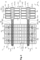
Figure 2 is a partial bottom view of an electromechanical system according to a first embodiment, this electromechanical system comprising capacitive detection or actuation means; -
Figure 3 is a partial top view of the capacitive detection or actuation means of the electromechanical system inFigure 2 ; -
Figure 4A is a cross-sectional view of the electromechanical system along sectional plane A-A inFigure 3 ; -
Figure 4B is a cross-sectional view of the electromechanical system along sectional plane C-C ofFigure 3 ; -
Figure 5 is a partial bottom view of an electromechanical system according to a second embodiment; -
Figure 6 is a partial top view of the electromechanical system inFigure 5 ; -
Figure 7 is a partial bottom view of an electromechanical system according to a third embodiment. - For the sake of clarity, identical or similar elements are marked by identical reference signs throughout the figures.
-
Figures 2 ,3 and4A to 4B represent a part of anelectromechanical system 2 with capacitive detection or capacitive actuation according to a first embodiment. Thiselectromechanical system 2 may form an electroacoustic transducer, for example a microphone or a loudspeaker, or a differential pressure sensor. In the following description, the example of a microphone with capacitive detection will be taken. - The
electromechanical system 2 comprises: - a
frame 10; - a
movable element 13 in contact with afirst zone 11; - capacitive detection (or measurement) means 15' comprising a
first electrode 151 movable relative to theframe 10, asecond electrode 152 movable relative to theframe 10, the first and second movable electrodes 151-152 being located in asecond zone 12 sealed from thefirst zone 11; and - a
first device 14a for transmitting movement between themovable element 13 and the first movable electrode 151 (i.e. between thefirst zone 11 and the second zone 12); and - a
second device 14b for transmitting movement between themovable element 13 and the secondmovable electrode 152. -
Figure 2 is a bottom view of theelectromechanical system 2 showingfirst portions 101 of theframe 10, themovable element 13, thetransmission devices 14a-14b and the movable electrodes 151-152 of the capacitive detection means 15'.Figure 3 is a top view showing only a part of the capacitive detection means 15' (including the first movable electrode 151).Figures 4A to 4B are different cross-sectional views of theelectromechanical system 2, respectively according to the cross-sectional planes A-Aand C-C represented inFigure 3 . They represent in part of theframe 10, thefirst transmission device 14a and the capacitive detection means 15'. - The
movable element 13, hereinafter referred to as the piston, is movable in translation relative to theframe 10, in a direction (Z) perpendicular to the plane (XY) ofFigure 2 . It preferably comprises amembrane 131 and arigidifying structure 132 for rigidifying themembrane 131, also referred to as a skeleton or armature. The role of themembrane 131 of thepiston 13 is to collect, over its entire surface, a pressure difference between its two faces, in order to deduce a variation in atmospheric pressure. - The
membrane 131 of thepiston 13 can partly delimit a closed reference volume, where a reference pressure prevails. It separates this reference volume from a cavity open to the outside environment. One face of themembrane 131 is therefore subjected to the reference pressure and an opposite face of themembrane 131 is subjected to atmospheric pressure (the variation of which is to be detected in the case of a microphone). Alternatively, the reference volume can be quasi-closed, in the sense that there is a trench around the piston (which is cut away). This trench allows the piston to move and allows air to leak between the reference volume and the outside. This leakage is small so that pressures can equalise slowly, filtering out only low-frequency pressure variations. - The
first zone 11 encompasses the cavity open to the outside environment, subjected to atmospheric pressure, and the reference volume subjected to the reference pressure. - The capacitive detection means 15' measure the displacement of the
piston 13, and therefore the pressure difference between its two faces. In addition to the first and second movable electrodes 151-152, they comprise at least one fixed electrode (relative to the frame 10), separated from the firstmovable electrode 151 by a first dielectric medium, and at least one additional fixed electrode, separated from the secondmovable electrode 152 by a second dielectric medium. - Each movable electrode and associated fixed electrode(s) form the armatures of one or several capacitors whose capacitance varies as a function of the displacement of the
piston 13. The fixed electrodes may also be called "counter-electrodes". - The first dielectric medium and the second dielectric medium are not solid (but are preferably constituted by a gas or a mixture of gases), so as not to hinder the movement of the
movable electrodes 151. The second dielectric medium is identical to the first dielectric medium, as the movable electrodes 151-152 are both located in thesecond zone 12. - Advantageously, the
second zone 12 is a controlled atmosphere chamber to reduce the phenomena of viscous friction and the associated acoustic noise. By "controlled atmosphere chamber" we mean a chamber under reduced pressure, typically less than 1000 mbar, and preferably less than 1 mbar. In this way, thesecond zone 12 is subjected to a pressure well below atmospheric pressure or the reference pressure. - The
first transmission device 14a is mounted so as to be rotatably movable relative to theframe 10, by means of several first pivot hinges 16a. It comprises afirst transmission shaft 144a and one or severalfirst transmission arms 145a, also known as lever arms. - The
first transmission shaft 144a has a first longitudinal axis of rotation Xa (hereinafter referred to as the first axis Xa), which extends in a first direction X. In other words, thefirst transmission shaft 144a can pivot on itself, about the first axis Xa. It extends opposite thepiston 13, opposite a zone located between thepiston 13 and the firstmovable electrode 151 and opposite the firstmovable electrode 151. - Advantageously, the first
movable electrode 151 is integral with thefirst transmission shaft 144a, which means that there is no relative movement between the firstmovable electrode 151 and thefirst transmission shaft 144a. The firstmovable electrode 151 is therefore also mounted so as to be rotatably movable about the first axis Xa. - The
electromechanical system 2 is thus devoid of movement transformation devices between thefirst transmission device 14a and the firstmovable electrode 151, such as torsion blades for switching from rotation to translation. As a result, no energy is lost in these transformation members (for example, by deformation of the torsion blades). - The
first transmission arms 145a, for example three in number inFigure 2 , can extend perpendicularly to the first axis Xa, in other words in a second direction Y perpendicular to the first direction X. The first and second directions X-Y, together with a third perpendicular direction Z, constitute an orthogonal reference frame. - Each
first transmission arm 145a comprises a first end coupled to thepiston 13 and a second end integral with thefirst transmission shaft 144a. One orseveral coupling elements 133 connect therigidifying structure 132 for thepiston 13 to the first end of eachfirst transmission arm 145a. A part at least of the coupling elements 133 (for example torsion blades) allow the transition from a translational movement (piston 13) to a rotational movement (first transmission shaft 144a and first movable electrode 151) while strongly coupling their displacement along the third direction Z. Thesecoupling elements 133 are capable of elastic deformation. - The translational movement of the
piston 13 causes thefirst transmission arms 145a, and therefore thefirst transmission shaft 144a, to rotate about the first axis Xa. This rotational movement is then transmitted to the firstmovable electrode 151. - The first pivot hinges 16a, for example six in number, are aligned, here in the first direction X. Preferably, one of the first pivot hinges 16a is located at the end of the
first transmission shaft 144a, on thepiston 13 side (i.e. opposite the first movable electrode 151), while other first pivot hinges 16a are located on the firstmovable electrode 151 side. As will be described in detail below, the firstmovable electrode 151 is preferably connected to thefirst transmission shaft 144a at these other first pivot hinges 16a. - The
second transmission device 14b is also mounted so as to be rotatably movable relative to theframe 10, by means of second pivot hinges 16b. It is constructed in the same way as thefirst transmission device 14a. More particularly, it comprises asecond transmission shaft 144b having a second longitudinal axis of rotation Xb (hereinafter referred to as the second axis Xb) andsecond transmission arms 145b (three, for example). Eachsecond transmission arm 145b comprises a first end coupled (via one or several coupling elements 133) to thepiston 13 and a second end integral with thesecond transmission shaft 144b. Thesecond transmission arms 145b preferably extend perpendicularly to the second axis Xb. - The second
movable electrode 152 is advantageously integral with thesecond transmission shaft 144b and therefore rotates about the second axis Xb. - The second pivot hinges 16b are preferably distributed along the second axis Xb in the same way as the first pivot hinges 16a are distributed along the first axis Xa (one of them is located at the end of the
second transmission shaft 144b and others are located at the second movable electrode 152). - The
first transmission arms 145a are coupled to a first half of the piston 13 (the upper half inFigure 2 ) and thesecond transmission arms 145b are coupled to a second half of the piston 13 (the lower half inFigure 2 ). In this way, thetransmission devices 14a-14b support thepiston 13 and hold it in translation. Preferably, thepiston 13 is held solely by the first andsecond transmission arms 145a-145b. In this way, a greater proportion of the energy collected by thepiston 13 is transmitted to the movable electrodes 151-152. - As illustrated in
Figure 2 , the first axis Xa and the second axis Xb are advantageously parallel. This helps to reduce the overall dimensions of theelectromechanical system 2 and provides uniform support for the piston. - The first
movable electrode 151 and the secondmovable electrode 152 can be identical and arranged symmetrically with respect to a plane P separating the first and second halves of thepiston 13. This symmetry makes it possible to obtain an identical reaction on the two halves of the piston so that the latter is held securely in translation. - The
first transmission device 14a and thesecond transmission device 14b can also be symmetrical with respect to the plane P. Thefirst transmission shaft 144a and the firstmovable electrode 151 then pivot in one direction (about the first axis Xa), while thesecond transmission shaft 144b and the secondmovable electrode 152 pivot in the opposite direction (about the second axis Xb). - The
piston 13 may also be symmetrical with respect to the plane P. - The symmetries of the
piston 13 and thetransmission devices 14a-14b enable the energy collected by thepiston 13 to be distributed equally between the firstmovable electrode 151 and the secondmovable electrode 152. Indeed, the mass of thepiston 13 is distributed equally between the first and second halves, and therefore between the first andsecond transmission devices 14a-14b. - Rotating the first
movable electrode 151 and the secondmovable electrode 152, along the same axis of rotation as thefirst transmission device 14a and thesecond transmission device 14b respectively, makes it possible to obtain a greater displacement of the movable electrodes 151-152 for a given displacement of thepiston 13, without however increasing the overall dimensions of theelectromechanical system 2. The movable electrodes 151-152 can therefore be as close as possible to thepiston 13. - The change from one movable electrode (
Fig.1 ) to two movable electrodes (Fig.2 ) does not significantly increase the overall dimensions of theelectromechanical system 2 either, as the two movable electrodes 151-152 can be arranged opposite each other in the extension of thepiston 13.. - The displacement of each
movable electrode piston 13 is a function of the distance Lpist1, Lpist2 between the first end of thetransmission shafts rotating electrode - More precisely, the displacement in Z of the longitudinal edge of the first
movable electrode 151 is given by the following relationship:

where dZpist is the displacement in Z of the piston 13 (and therefore of all the first ends of the first andsecond transmission arms 145a-145b), L elec1 is the distance between the longitudinal edge of the firstmovable electrode 151 and the first axis Xa and Lpist1 is the distance between the first end of eachfirst transmission arm 145a and the first axis Xa. - The Z displacement of the longitudinal edge of the second
movable electrode 152 is given by the following relationship:

where Lelec2 is the distance between the longitudinal edge of the secondmovable electrode 152 and the second axis Xb and Lpist2 is the distance between the first end of eachsecond transmission arm 14b and the second axis Xb. - The
transmission shafts 144a-144b and thetransmission arms 145a-145b can be particularly rigid, and therefore not very sensitive to deformations which are equivalent to energy losses. This rigidity of thetransmission shafts 144a-144b and thetransmission arms 145a-145b can in particular be conferred by a large thickness (measured in the third direction Z), preferably between 5 µm and 800 µm, and more preferably between 50 µm and 200 µm. Thetransmission shafts 144a-144b and thetransmission arms 145a-145b are advantageously formed by etching a substrate. This substrate can be thinned to a thickness less than 200 µm. - As the
transmission shafts 144a-144b rotate on themselves, their inertia remains low and does not have a negative impact on the resonance frequency of theelectromechanical system 2. However, they can be apertured, as illustrated inFigure 2 , in order to optimise their stiffness to inertia ratio. Thetransmission shafts 144a-144b are preferably perforated at least in the portion facing thepiston 13. This also makes it possible to limit damping with the piston 13 (known as "squeeze film damping"), which is a source of noise. - The width of the
transmission shafts 144a-144b (measured in the first direction Y) is of the same order of magnitude as their thickness, in order to minimise their inertia. Advantageously, it is between 5 µm and 800 µm. - The capacitive detection means 15' will now be described in more detail, with reference only to the first movable electrode 151 (connected to the
first transmission device 14a). Nevertheless, this description applies mutatis mutandis to the second movable electrode 152 (connected to thesecond transmission device 14b), since it may be identical to thefirst electrode 151. Similarly, the description that will be given of the first pivot hinges 16a applies to the second pivot hinges 16b. - With reference to
Figures 2 and3 , thefirst electrode 151 may comprise amembrane 1511 and arigidifying structure 1512 of themembrane 1511. Therigidifying structure 1512 preferably comprises a plurality offirst beams 1512a extending parallel to one another. It may further comprisesecond beams 1512b connecting thefirst beams 1512a at their ends. - The
first beams 1512a preferably extend in the second direction Y, advantageously from a first edge to an opposite second edge of the firstmovable electrode 151. They are advantageously evenly spaced from one another, to rigidity themembrane 1511 uniformly. Thesecond beams 1512b preferably extend in the first direction X (i.e. perpendicularly to thefirst beams 1512a). - The first
movable electrode 151 advantageously has one or several planes of symmetry, for example a plane parallel to the XZ plane (therefore perpendicular to thefirst beams 1512a) and another plane parallel to the YZ plane. - The
rigidify structure 1512 of the firstmovable electrode 151 is advantageously anchored, or fused, to thefirst transmission device 14a at a part of the first pivot hinges 16a. Compared with the microphone 1 ofFig. 1 , theelectrostatic system 2 therefore lacks thesecond transmission arms 142 extending into thesecond zone 12. - More particularly, the
rigidify structure 1512 of the firstmovable electrode 151 is connected to thefirst transmission device 14a, and more particularly to thefirst transmission shaft 144a, bypillars 146 visible inFigures 4A and 4C. Thepillars 146 of thefirst transmission device 14a are similar to thetransmission shafts 143 ofFig. 1 , in that they extend partly into thefirst zone 11 and partly into thesecond zone 12. Indeed, the seal between thefirst zone 11 and thesecond zone 12 is also made at the level of the first pivot hinges 16a associated with the firstmovable electrode 151. - The
first transmission device 14a is thus reduced to first elements extending exclusively in the first zone 11 (thefirst transmission shaft 144a and thefirst transmission arms 145a) and to second elements (the pillars 146) which extend partly in thefirst zone 11 and partly in thesecond zone 12. This reduction of thefirst transmission device 14a makes it possible to limit energy losses. In particular, there are no more losses due to deformation of thesecond transmission arms 142. - The
electromechanical system 2 is particularly compact, as several functions, namely the rotation of thefirst transmission device 14a, the seal between the two zones 11-12 and the connection to the firstmovable electrode 151, are carried out in the same place. - Anchoring between the
rigidifying structure 1512 and thefirst transmission device 14a is preferably achieved by means of thefirst beams 1512a. A part at least of these are fused to thefirst transmission device 14a, each at a correspondingfirst pivot hinge 16a. The anchoring point of eachfirst beam 1512a is advantageously located halfway along its length. Thus, the axis of rotation of the firstmovable electrode 151 lies in one of the planes of symmetry of the first movable electrode 151 (that perpendicular to thefirst beams 1512a). The length of thefirst beams 1512a is measured in the second direction Y, while their width is measured in the first direction X. - Each
first beam 1512a merged with thefirst transmission device 14a advantageously has a width which decreases away from the correspondingfirst pivot hinge 16a. In other words, the width of thefirst beams 1512a is maximum at the level of the first pivot hinges 16a. - In this first embodiment of the
electromechanical system 2, each of thefirst beams 1512a of thestiffening structure 1512 is fused to thefirst transmission device 14a. In other words, eachfirst beam 1512a is associated with afirst pivot hinge 16a. The number of first pivot hinges 16a on the side of the firstmovable electrode 151 is therefore equal to the number offirst beams 1512a. This arrangement makes it possible to create aspace 17 between two successive first pivot hinges 16a. - For each
first pivot hinge 16a, theframe 10 may comprise two distinctfirst portions 101 arranged on either side of thefirst beam 1512a associated with the first pivot hinge. Thefirst beam 1512a is preferably connected to each of thefirst portions 101 of theframe 10 by a torsion bar 162 (seeFig. 3 ). - As represented by
Figures 3 ,4A and 4B , the capacitive detection means 15' preferably comprise two counter-electrodes 153-154 associated with the first movable electrode 151: a first counter-electrode 153 referred to as positive and asecond counter-electrode 154 referred to as negative. Preferably, at least a part of themembrane 1511 of the firstmovable electrode 151 is located between the two counter-electrodes 153-154 (seeFigs.4A-4B ). The firstmovable electrode 151 and the counter-electrodes 153-154 thus form the armatures of two capacitors whose capacitances vary in opposite directions. A differential measurement of the displacement of thepiston 13 can thus be obtained. The surfaces of the counter-electrodes 153-154 facing the firstmovable electrode 151 are advantageously identical, thanks to the symmetry of the firstmovable electrode 151 and of the counter-electrodes 153-154 with respect to the first pivot hinges 16a (the plane of symmetry coincides with the sectional plane C-C). - Advantageously, each of the counter-electrodes 153, 154 comprises a
first portion second portion membrane 1511 and on either side of the first pivot hinges 16a. Thefirst portion second portion membrane 1511 and theupper portions 153a-154a of the counter-electrodes (referred to as the upper air gap) is different from the distance between themembrane 1511 and thelower portions 153a-154a of the counter-electrodes (lower air gap). - The
lower portions 153b-154b of the counter-electrodes 153-154 extend under thefirst beams 1512a of thestiffening structure 1512, on either side of the first pivot hinges 16a. In contrast, theupper portions 153a-154a of the counter-electrodes 153-154 are preferably each divided into several blocks (or sub-portions) separated by thefirst beams 1512a, as illustrated inFigure 3 . As theupper portions 153a-154a of the counter-electrodes 153-154 are inscribed in thestiffening structure 1512, their surface zone facing themembrane 1511 is smaller than that of thelower portions 153b-154b. - With reference to
Figure 4A , thelower portions 153b-154b of the counter-electrodes 153-154 are preferably secured to anannular portion 102 of theframe 10, located at the periphery of the firstmovable electrode 151, by means ofannular seals lower portion annular seals first zone 11 and thesecond zone 12. - Alternatively, the capacitive detection means 15' may comprise (for each movable electrode) only one counter-electrode (lower or upper), two counter-electrodes (upper and lower) but located on only one side of the pivot hinges 16 (pseudo-differential detection) or even two lower or upper counter-electrodes arranged on either side of the pivot hinges 16 (differential detection).
- As previously indicated, the seal between the first and second zones 11-12 of the
electromechanical system 2 can be made at the first pivot hinges 16a located on the side of the firstmovable electrode 151. As illustrated inFigures 4A and 4B , eachfirst pivot hinge 16a associated with the firstmovable electrode 151 comprises a sealed insulatingelement 161, capable of elastically deforming under the effect of the rotational displacement of thefirst transmission device 14a. The sealed insulatingelement 161 is preferably in the form of a sealing membrane. - Each sealed insulating
element 161 is preferably traversed by an associatedpillar 146 of thefirst transmission device 14a. The sealed insulatingelement 161 extends, for example, from the associatedpillar 146 to thelower portions 153b-154b of the counter-electrodes 153-154 (seeFig. 4A ) and to thefirst portions 101 of the frame 10 (seeFig. 4B ), to which it is anchored by means of theannular seals - In addition, each
first pivot hinge 16a (associated with the first movable electrode 151) advantageously comprises two torsion blades 162 (one perfirst portion 101 of the frame 10). Thetorsion blades 162 are dimensioned so as to be able to deform in torsion and allow thefirst transmission device 14a and the firstmovable electrode 151 to rotate, while limiting their translational movements, in particular in the third Z direction (so-called "out-of-plane" translation). The twotorsion blades 162 connect therigidifying structure 1512 of the first movable electrode 151 (fused to thepillar 146 of thefirst transmission device 14a) to thefirst portions 101 of the frame 10 (see also Fig. 4C). They are preferably aligned and arranged diametrically opposite thefirst beam 1512a associated with thefirst pivot hinge 16a. - The
first pivot hinge 16a located at the end of thefirst transmission shaft 144a advantageously comprises a sealed insulating element 161 (preferably in the form of a membrane) and twotorsion blades 162, but does not participate in the sealing between the first and second zones 11-12 (being located only in the first zone 11). - The
electromechanical system 2 comprises elastic means connected to the firstmovable electrode 151 and configured to generate an elastic force which opposes the movement of the firstmovable electrode 151. The role of these elastic means is to combat the pull-in phenomenon of the firstmovable electrode 151. Their stiffness influences the collapse voltage (or "pull-in voltage" of the system), and therefore the ability to bias the firstmovable electrode 151. - The elastic "anti-pull-in" means connect (mechanically) the
rigidifying structure 1512 of the firstmovable electrode 151 to theframe 10 and/or to elements integral with the frame, such as the counter-electrodes 153-154, possibly via thepillars 146 of thefirst transmission device 14a. Thus, the stiffness of thefirst transmission device 14a or the stiffness of therigidifying structure 1512 itself are not considered to be "anti-pull-in" elastic means. - The "anti-pull-in" elastic means here comprise the sealed insulating
elements 161 and, where appropriate, thetorsion blades 162. The sealedinsulating elements 161 and thetorsion blades 162 thus perform several functions simultaneously. - The anti-pull-in elastic means are connected to the
rigidifying structure 1512 where it is most rigid, i.e. at the first pivot hinges 16a. In this way, the stiffness of the anti-pull-in spring means is not degraded by series elements of too low stiffness. This stiffness can also be easily controlled by adjusting the dimensions of the sealed insulatingelements 161 and thetorsion blades 162. The sealedinsulating elements 161 can be defined by anisotropic etching of a sacrificial layer (SiO2, for example) and are produced in a structural layer of controlled thickness. This type of etching gives good control over the dimensions of the sealed insulatingelements 161. As a result, the stiffness of the sealed insulatingelements 161 shows little dispersion (mainly between the different electromechanical systems manufactured on the same wafer or on different wafers). - The second
movable electrode 152 is advantageously connected to thesecond transmission device 14b in the same way as the firstmovable electrode 151 is connected to thefirst transmission device 14a. Thus, theelectromechanical system 2 also comprises "anti-pull-in" elastic means connected to the secondmovable electrode 152, these elastic means preferably comprising the sealed insulatingelements 161 and, where appropriate, thetorsion blades 162 of the second pivot hinges 16b. - The sealed
insulating elements 161 and, where applicable, thetorsion blades 162, advantageously constitute the only "anti-pull-in" means of theelectromechanical system 2. Theelectromechanical system 2 is therefore particularly compact. - The
electromechanical system 2 described above can be manufactured using the methods described in patentsFR3059659B1 FR3114584B1 - The substrate is used in particular to produce, by etching, the first elements of the
transmission devices 14a-14b (transmission shafts 144a-144b andtransmission arms 145a-145b), the lower portions of the counter-electrodes 153-154 and a part of theframe 10. The substrate may be made of a semiconductor material, for example silicon. - The first structural layer is used in particular to produce the
membrane 131 of thepiston 13, themembrane 1511 of the movable electrodes 151-152 and the sealed insulating elements 161 (sealing membranes). Its thickness is less than that of the substrate, preferably between 100 nm and 10 µm. It is preferably constituted from the same material as the substrate, for example silicon. - The first sacrificial layer is intended to disappear in part during manufacture of the
electromechanical system 2 to free themembrane 131 of thepiston 13, themembrane 1511 of the movable electrodes 151-152 and the sealed insulatingelements 161. In particular, its thickness defines the distance between themembrane 1511 and the lower portions of the counter-electrodes 153-154 (lower air gap). This layer also acts as a stop layer during etching of the substrate, the membrane 152a and the second structural layer (the "MEMS" layer described later). The remaining parts of the first sacrificial layer form theannular seals - As described in the aforementioned patents, a second sacrificial layer is deposited on the first structural layer and a second structural layer is formed on the second sacrificial layer, preferably by epitaxy.
- The second structural layer is etched to define at least a part of the
rigidification structure 132 of thepiston 13, therigidification structure 1512 of the movable electrodes 151-152, thetorsion blades 162, the upper portions of the counter-electrodes 153-154, thefirst portions 101 and the secondannular portion 102 of theframe 10. Advantageously, it is made of the same material as the first structural layer, for example silicon. The thickness of the second structural layer is preferably between 5 µm and 50 µm. - The
rigidifying structure 1512 of eachmovable electrode corresponding transmission device pillars 146 of thetransmission devices - The second sacrificial layer is used in particular as a stop layer during etching of the second structural layer. It is partly removed to free the
membrane 131 of thepiston 13, themembrane 1511 of the movable electrodes 151-152 and the sealed insulatingelements 161. Its thickness defines the distance between themembrane 1511 and the upper portions of the counter-electrodes 153-154 (upper air gap). The second sacrificial layer is advantageously formed from the same dielectric material as the first sacrificial layer, for example silicon oxide. Its thickness can be between 100 nm and 10 µm. -
Figures 5 and6 represent a second embodiment of theelectromechanical system 2.Figure 5 is a bottom view of a part of theelectromechanical system 2, similar toFigure 2 .Figure 6 is a top view of the same part of theelectromechanical system 2. - This second embodiment differs from the first embodiment mainly in that the
electromechanical system 2 comprises two movable elements or pistons, rather than a single one. - Thus, in addition to the
frame 10, the first andsecond transmission devices 14a-14b and the capacitive detection means 15' comprising the two movable electrodes 151-152, theelectromechanical system 2 comprises afirst piston 13a and asecond piston 13b. - The
first piston 13a is connected, on the one hand, to the firstmovable electrode 151 by thefirst transmission device 14a, and, on the other hand, to the secondmovable electrode 152 by thesecond transmission device 14b. - The
second piston 13b is connected, on the one hand, to the firstmovable electrode 151 by thefirst transmission device 14a and, on the other hand, to the secondmovable electrode 152 by thesecond transmission device 14b. - Thus, each
transmission device pistons 13a-13b to the capacitive detection means 15', and more particularly to themovable electrode transmission device - The way in which the movable electrodes 151-152 are constructed and the way in which they are connected to the
transmission devices 14a-14b have been described previously in relation toFigures 2 ,3 and4A-4B . The movable electrodes 151-152 inFigure 5 are simply smaller than those inFigure 2 , in order to best represent the two pistons. - The capacitive detection means 15' can be located between the two
pistons 13a-13b. Each of thepistons 13a-13b separates a cavity open to the outside from a reference volume. Thus, in this configuration, thefirst zone 11 comprises two cavities open to the outside and two reference volumes (which can communicate with each other). Thesecond zone 12, which contains the movable electrodes 151-152, is located between thepistons 13a-13b. - The
pistons 13a-13b are subjected to the same pressure difference. They are also mounted so that they can move relative to theframe 10 in the same way, preferably in translation along the third direction Z. Thepistons 13a-13b therefore have the same displacement. - The
pistons 13a-13b each comprise amembrane 131 and amembrane rigidifying structure 132. Thefirst piston 13a has an effective surface zone and mass equal to or approximately equal (within 5%) to those of thesecond piston 13b. The effective surface zone of a piston is defined as the surface zone in contact with the first zone 11 (in other words the surface zone that harvests the pressure difference). Theelectromechanical system 2 is therefore balanced overall. - Viewed from the front, the
pistons 13a-13b preferably have the same shape, for example rectangular with rounded corners. The dimensions (length, width) of thefirst piston 13a are equal or substantially equal (to within 5%) to those of thesecond piston 13b. The width of a piston is measured in the first direction X and its length is measured in the second direction Y. - For example, the two
pistons 13a-13b inFigure 5 have the same length (measured in Y) as thesingle piston 13 inFigure 2 , but a width (measured in X) less than or equal to half that ofpiston 13. - For an equivalent piston surface zone, the
electromechanical system 2 comprising two pistons offers better performance, particularly in terms of sensitivity and resonant frequency, because it offers a better compromise between rigidity and mass than the electromechanical system comprising a single piston (Figure 2 ). - Indeed, as the two
pistons 13a-13b are smaller than a single piston, they are more rigid, all other things being equal (thickness, rigidifying structure, etc.), and are therefore subject to less deformation. They can be more rigid for the same (cumulative) mass or be lighter for the same level of rigidity, or even lighter while being more rigid. In addition, the parts of thetransmission devices 14a-14b that hold thepistons 13a-13b (each located between two pivot hinges 16a, 16b positioned on either side of a piston) are shorter (due to the smaller width of the pistons) and can therefore be lightened without reducing their rigidity. - The
pistons 13a-13b are advantageously identical. They can be arranged symmetrically with respect to a plane passing through the movable electrodes 151-152. Similarly, thetransmission devices - As in the first embodiment (see
Fig. 2 ), thefirst transmission device 14a is mounted so as to rotate relative to theframe 10 by means of several first pivot hinges 16a. In the embodiment shown inFigure 5 , at least one of the first pivot hinges 16a is located at the firstmovable electrode 151, anotherfirst pivot hinge 16a is located at a first end of thefirst transmission device 14a (beyond thefirst piston 13a) and yet anotherfirst pivot hinge 16a is located at a second opposite end of thefirst transmission device 14a (beyond thesecond piston 13b). - The
second transmission device 14b is rotatably mounted relative to theframe 10 by means of the second pivot hinges 16b. The second pivot hinges 16b are preferably arranged in the same way as the first pivot hinges 16a. - In this second embodiment, each
transmission device - a
transmission shaft movable electrode - one or more transmission arms (or lever arms) 145a, 145b having a first end integral with the
transmission shaft first piston 13a; - one or more additional transmission arms (or lever arms) 145c, 145d having a first end integral with the
transmission shaft second piston 13b. - Advantageously, the
transmission devices - The
first piston 13a and the way in which it is connected to thetransmission devices 14a-14b will now be described in more detail. This description applies mutatis mutandis to thesecond piston 13b. - Thus, the
rigidifying structure 132 for thefirst piston 13a advantageously comprises, on the side of themembrane 131 where thetransmission devices 14a-14b are located, afirst beam 1321 which extends along the length of thefirst piston 13a. Thefirst beam 1321 can extend along the median line M of thefirst piston 13a, as represented inFigure 5 , or parallel to this median line M at a distance of less than a quarter of the width of thefirst piston 13a. Thisfirst beam 1321 advantageously has the same thickness as thetransmission shafts transmission arms - Thanks to its great thickness, the
first beam 1321 contributes greatly to rigidifying thefirst piston 13a in its greatest dimension (length) and therefore to reducing the deformation of thefirst piston 13a. It therefore provides a significant gain in sensitivity. - The
first beam 1321 preferably extends over more than 50% of the length of thefirst piston 13a. - Preferably, on this side of the
membrane 131, therigidifying structure 132 comprises only thefirst beam 1321. - On the other side of the
membrane 131, represented byFigure 6 , therigidifying structure 132 for thefirst piston 13a advantageously comprises asecond beam 1322 superimposed on thefirst beam 1321. Thissecond beam 1322 has a thickness strictly less than that of thefirst beam 1321. It can be formed in the second structural layer described above, the thickness of which is between 5 µm and 50 µm. Thesecond beam 1322 can have a length equal to that of thefirst beam 1321. - The
second beam 1322 thus extends at least part of thefirst beam 1321 in the third direction Z to reach a greater thickness. It only slightly increases the mass of thefirst piston 13a (to a lesser extent than thefirst beam 1321, due to its smaller thickness), but considerably increases the rigidity of the piston (as this varies as a function of the cube thickness). - On the same side as the
second beam 1322, therigidifying structure 132 may also compriseedges 1323 oriented perpendicularly to the first beam 1321 (so preferably parallel to the first axis Xa). Theseridges 1323 rigidity thefirst piston 13a across its width. As the width is the smallest side of thefirst piston 13a, theridges 1323 do not need to be thick (unlike the first beam 1321). Theedges 1323 preferably have the same thickness as the second beam 1322 (between 5 µm and 50 µm). In this way, they do not significantly increase the mass of thefirst piston 13a. They are also formed by etching the second structural layer. They can extend from one edge of thefirst piston 13a to the other. - A part at least of the
edges 1323 may come to bear against stop elements belonging to the frame of theelectromechanical system 2. These stop elements, for example in the form of a beam extending opposite theedges 1323, are provided to prevent the destruction of thefirst piston 13a and themovable electrodes first piston 13a is subjected to a very large pressure difference (such as during reliability tests). - Finally, the
rigidifying structure 132 may comprise a frame 1324 located at the periphery of thefirst piston 13a. This frame 1324 preferably has the same thickness as thesecond beam 1322. It may also be formed by etching the second structural layer. - Multiplying the number of pistons considerably simplifies their rigidifying structure. The mass of the two
pistons 13a-13b is reduced compared with that of thepiston 13 inFigure 2 , while their rigidity is increased. This represents a twofold gain in performance. - The
electromechanical system 2 does not necessarily comprise the two movable electrodes 151-152 and the twotransmission devices 14a-14b. It may comprise a single movable electrode and a single transmission device (seeFig.7 ), or a single movable electrode and two transmission devices connected to this single movable electrode. -
Figure 7 represents a third embodiment in which theelectromechanical system 2 comprises, in addition to the twopistons 13a-13b, a single movable electrode 151 (for example of the type represented byFigure 5 ) and asingle transmission device 14a (for example of the type represented byFigure 5 ). - The
pistons 13a-13b are here rotatably movable about an axis Xp (and not translatable), by means of pivot hinges or hinges (not represented) distinct from the first pivot hinges 16a. The rotational movement of thepistons 13a-13b (about the axis Xp) rotates thetransmission shaft 144a of thetransmission device 14a (about its own axis Xa), via thetransmission arms transmission shaft 144a moves the movable electrode 151 (here in rotation about the axis Xa). - The
electromechanical system 2 is not limited to the embodiments described in relation toFigures 2 to 7 and many alternatives and modifications of the electromechanical system will become apparent to the person skilled in the art. - In particular, the
first piston 13a and thesecond piston 13b may be connected to the capacitive detection means 15', and in particular to the first movable electrode 151 (or to the first and second movable electrodes 151-152) by two (four) separate transmission devices. - Furthermore, the
second piston 13b is not necessarily connected to the same movable electrode (or the same movable electrodes) as thefirst piston 13a. Thus, thefirst piston 13a may be connected to the firstmovable electrode 151 by a first transmission device, while thesecond piston 13b is connected to the secondmovable electrode 152 by a second transmission device. - The
transmission devices 14a-14b, and more particularly thetransmission shafts 144a-144b, can adopt other geometries. The number oftransmission arms - The
electromechanical system 2 may also comprise, for eachtransmission device transmission shaft movable electrode first zone 11 and therefore do not contribute to the seal between the two zones. - Conversely, the electromechanical system of
Figures 5 to 7 (two pistons) may include only three pivot hinges pertransmission device movable electrode transmission shaft - The
electromechanical system 2 has been described taking as an example a microphone with capacitive detection comprising one orseveral pistons membrane 131 subjected on the one hand to atmospheric pressure and on the other hand to a reference pressure. However, the electromechanical system can form other types of capacitive detection transducer, in particular a loudspeaker (sound emitter) or an ultrasound emitter (which are electroacoustic transducers), or even a differential pressure sensor. - In the case of a differential pressure sensor, the first face of the membrane 131 (of each piston) is subjected to a first pressure (not necessarily atmospheric pressure) and the second face of the
membrane 131 is subjected to a second pressure, different from the first pressure. The displacement of themembrane 131, under the effect of the pressure difference, is measured by the capacitive detection means 15'. Themembrane 131 of the piston is integral with theframe 10 so as to be sealed and therigidifying structure 132 of the piston is absent or reduced so as not to anchor it to the frame. - In the case of a loudspeaker or an ultrasound transmitter, capacitive actuation means replace the capacitive detection means 15'. These capacitive actuation means also comprise two movable electrodes and at least one counter-electrode per movable electrode. The movable electrodes are moved by an electrostatic force and this movement is transmitted by the
transmission devices piston 13 orpistons 13a-13b. The movement of themembrane 131 of the piston orpistons - The
second zone 12 may comprise two chambers under a controlled atmosphere, one containing the firstmovable electrode 151, the other containing the secondmovable electrode 152. - The first and second sealed zones 11-12 are not necessarily subjected to different pressures. The
first zone 11 may also be an aggressive environment and the movable electrodes of the capacitive means (of detection or actuation) are placed in thesecond zone 12 to protect them from this aggressive environment (in addition to reducing viscous friction, and therefore acoustic noise). - The
electromechanical system 2 may even be devoid of sealing means between the first and second zones 11-12 (which amounts to considering only one zone). More particularly, the pivot hinges 16 may not have any sealed insulatingelement 161. Indeed, thetorsion blades 162 may suffice for the rotation of thetransmission device
Claims (13)
- An electromechanical system (2) comprising:- a frame (10);- a first element (13a) movable relative to the frame (10); and- capacitive measurement or actuation means (15') comprising:∘ a first electrode (151) movable relative to the frame (10); and∘ at least one electrode (153, 154) fixed relative to the frame (10) and separated from the first movable electrode (151) by a first dielectric medium;- a first movement transmission device (14a) connecting the first movable element (13a) to the first movable electrode (151), the first transmission device (14a) being rotatably movable relative to the frame (10) by means of a plurality of first pivot hinges (16a);characterised in that it further comprises a second element (13b) movable relative to the frame (10) and in that the second movable element (13b) is connected to the capacitive measurement or actuation means (15').
- The system (2) according to claim 1, wherein the first movement transmission device (14a) further connects the second movable element (13b) to the first movable electrode (151).
- The system (2) according to claim 2, wherein the capacitive measurement or actuation means (15') further comprises:- a second electrode (152) movable relative to the frame (10); and- at least one additional electrode fixed relative to the frame (10) and separated from the second movable electrode (152) by a second dielectric medium;the system further comprising a second movement transmission device (14b) connecting the first movable element (13a) and the second movable element (13b) to the second movable electrode (152), the second transmission device (14b) being rotatably movable relative to the frame (10) by means of a plurality of second pivot hinges (16b).
- The system (2) according to one of claims 2 and 3, wherein the first transmission device (14a) comprises:- a first transmission shaft (144a) having a first longitudinal axis of rotation (Xa);- at least one first transmission arm (145a) comprising a first end coupled to the first movable element (13a) and a second end integral with the first transmission shaft (144a); and- at least one second transmission arm (145c) comprising a first end coupled to the second movable element (13b) and a second end integral with the first transmission shaft (144a).
- The system (2) according to any one of claims 1 to 4, wherein each of the first and second movable elements (13a, 13b) comprises a membrane (131) and a rigidifying structure (132) for rigidifying the membrane.
- The system (2) according to claim 5, wherein the first transmission device (14a) is located on a first side of the membrane (131) of the first movable element (13a) and wherein the rigidifying structure (132) of the first movable element comprises a first beam (1321) located on the first side of the membrane (131), the first beam (1321) extending in the length direction of the first movable element (13a), preferably along a median line (M) of the first movable element (13a).
- The system (2) according to claim 6, wherein the first beam (1321) has a length greater than or equal to 50% of the length of the first movable element (13a).
- The system (2) according to one of claims 6 and 7, wherein the rigidifying structure (132) of the first movable element (13a) further comprises a second beam (1322) located on a second opposite side of the membrane (131) and superimposed on the first beam (1321).
- The system (2) according to any one of claims 6 to 8, wherein the rigidifying structure (132) of the first movable element (13a) further comprises ridges (1323) located on a second opposite side of the membrane (131) and extending perpendicularly to the first beam (1321).
- The system (2) according to any one of claims 1 to 9, wherein the first movable element (13a) and the second movable element (13b) are identical.
- The system (2) according to any one of claims 1 to 10, wherein the capacitive measurement or actuation means (15') are located between the first movable element (13a) and the second movable element (13b).
- The system (2) according to claim 11, wherein:- at least one of the first pivot hinges (16a) is located at the first movable electrode (151),- another of the first pivot hinges (16a) is located at a first end of the first transmission device (14a);- another of the first pivot hinges (16a) is located at a second, opposite end of the first transmission device (14a).
- A system (2) according to any one of claims 1 to 12, wherein the first movable element (13a) and the second movable element (13b) are in contact with a first zone (11) and the first movable electrode (151) is located in a second zone (12) sealingly isolated from the first zone (11).
Applications Claiming Priority (1)
| Application Number | Priority Date | Filing Date | Title |
|---|---|---|---|
| FR2315317 | 2023-12-26 |
Publications (1)
| Publication Number | Publication Date |
|---|---|
| EP4578822A1 true EP4578822A1 (en) | 2025-07-02 |
Family
ID=90720854
Family Applications (1)
| Application Number | Title | Priority Date | Filing Date |
|---|---|---|---|
| EP24223160.3A Pending EP4578822A1 (en) | 2023-12-26 | 2024-12-24 | Electromechanical system comprising two movable elements and capacitive measurement or actuation means |
Country Status (3)
| Country | Link |
|---|---|
| US (1) | US20250211919A1 (en) |
| EP (1) | EP4578822A1 (en) |
| CN (1) | CN120213280A (en) |
Citations (5)
| Publication number | Priority date | Publication date | Assignee | Title |
|---|---|---|---|---|
| EP2541222A1 (en) * | 2011-07-01 | 2013-01-02 | Commissariat à l'Énergie Atomique et aux Énergies Alternatives | Pressure-measurement device with optimised sensitivity |
| EP2921836A1 (en) * | 2014-03-19 | 2015-09-23 | Commissariat à l'Énergie Atomique et aux Énergies Alternatives | Sensor for measuring microelectromechanical and/or nanoelectromechanical differential pressure |
| FR3059659B1 (en) | 2016-12-07 | 2019-05-17 | Commissariat A L'energie Atomique Et Aux Energies Alternatives | DEVICE FOR TRANSMITTING MOVEMENT AND FORCE BETWEEN TWO ZONES ISOLATED FROM EACH OTHER |
| EP3766829A1 (en) * | 2019-07-18 | 2021-01-20 | Commissariat à l'Energie Atomique et aux Energies Alternatives | Mechanical link for mems and nems device for measuring a pressure variation and device comprising such a mechanical link |
| FR3114584B1 (en) | 2020-09-29 | 2022-09-16 | Commissariat Energie Atomique | METHOD FOR MANUFACTURING AN ELECTROACOUSTIC TRANSDUCER |
-
2024
- 2024-12-23 US US18/999,173 patent/US20250211919A1/en active Pending
- 2024-12-24 EP EP24223160.3A patent/EP4578822A1/en active Pending
- 2024-12-26 CN CN202411941036.XA patent/CN120213280A/en active Pending
Patent Citations (5)
| Publication number | Priority date | Publication date | Assignee | Title |
|---|---|---|---|---|
| EP2541222A1 (en) * | 2011-07-01 | 2013-01-02 | Commissariat à l'Énergie Atomique et aux Énergies Alternatives | Pressure-measurement device with optimised sensitivity |
| EP2921836A1 (en) * | 2014-03-19 | 2015-09-23 | Commissariat à l'Énergie Atomique et aux Énergies Alternatives | Sensor for measuring microelectromechanical and/or nanoelectromechanical differential pressure |
| FR3059659B1 (en) | 2016-12-07 | 2019-05-17 | Commissariat A L'energie Atomique Et Aux Energies Alternatives | DEVICE FOR TRANSMITTING MOVEMENT AND FORCE BETWEEN TWO ZONES ISOLATED FROM EACH OTHER |
| EP3766829A1 (en) * | 2019-07-18 | 2021-01-20 | Commissariat à l'Energie Atomique et aux Energies Alternatives | Mechanical link for mems and nems device for measuring a pressure variation and device comprising such a mechanical link |
| FR3114584B1 (en) | 2020-09-29 | 2022-09-16 | Commissariat Energie Atomique | METHOD FOR MANUFACTURING AN ELECTROACOUSTIC TRANSDUCER |
Also Published As
| Publication number | Publication date |
|---|---|
| US20250211919A1 (en) | 2025-06-26 |
| CN120213280A (en) | 2025-06-27 |
Similar Documents
| Publication | Publication Date | Title |
|---|---|---|
| JP5825899B2 (en) | MEMS dynamic pressure sensor with special application to microphone manufacturing | |
| Esashi et al. | Vacuum-sealed silicon micromachined pressure sensors | |
| US8818007B2 (en) | MEMS-type pressure pulse generator | |
| US8374371B2 (en) | Miniature non-directional microphone | |
| US10807858B2 (en) | Device for transmitting a movement and a force between two zones that are insulated from one another | |
| US11337016B2 (en) | Mechanical connection for a MEMS and NEMS device for measuring a variation in pressure, and device comprising such a mechanical connection | |
| KR20170017788A (en) | System and method for a pumping speaker | |
| CN107110731B (en) | Dynamic pressure sensor with improved operation | |
| CN103518138A (en) | A method of manufacturing an inertial sensor | |
| Miani et al. | Resonant accelerometers based on nanomechanical piezoresistive transduction | |
| WO2005043173A1 (en) | Trapped charge field bias vibrating beam accelerometer | |
| CN114339558A (en) | Method of manufacturing an electroacoustic transducer | |
| US20210292158A1 (en) | Microelectromechanical microphone with reduced overall size | |
| US12634636B2 (en) | Electromechanical system comprising capacitive measurement or actuation means | |
| EP4674806A1 (en) | Electromechanical system comprising two movable elements side by side | |
| Wang et al. | Contamination-insensitive differential capacitive pressure sensors | |
| US20250211919A1 (en) | Electromechanical system comprising two movable elements and capacitive measurement or actuation means | |
| US12563347B2 (en) | Electromechanical system comprising capacitive measurement or actuation means and a transmission shaft | |
| US20250361138A1 (en) | Electromechanical system comprising a movable element provided with an opening | |
| Ozdogan et al. | A MEMS microphone using repulsive force sensors | |
| CN115931185A (en) | Capacitive micro-electromechanical sensor | |
| Okandan et al. | Optical microphone structures fabricated for broad bandwidth and low noise | |
| Bourouina et al. | Preliminary results on a silicon gyrometer based on acoustic mode coupling in small cavities | |
| Krenkel et al. | Modeling and validation of CMUTs with mechanically coupled plate actuators | |
| US20230403513A1 (en) | Electrostatic transducer and method of manufacturing electrostatic transducer |
Legal Events
| Date | Code | Title | Description |
|---|---|---|---|
| PUAI | Public reference made under article 153(3) epc to a published international application that has entered the european phase |
Free format text: ORIGINAL CODE: 0009012 |
|
| STAA | Information on the status of an ep patent application or granted ep patent |
Free format text: STATUS: REQUEST FOR EXAMINATION WAS MADE |
|
| 17P | Request for examination filed |
Effective date: 20241224 |
|
| AK | Designated contracting states |
Kind code of ref document: A1 Designated state(s): AL AT BE BG CH CY CZ DE DK EE ES FI FR GB GR HR HU IE IS IT LI LT LU LV MC ME MK MT NL NO PL PT RO RS SE SI SK SM TR |
|
| GRAP | Despatch of communication of intention to grant a patent |
Free format text: ORIGINAL CODE: EPIDOSNIGR1 |
|
| STAA | Information on the status of an ep patent application or granted ep patent |
Free format text: STATUS: GRANT OF PATENT IS INTENDED |
|
| INTG | Intention to grant announced |
Effective date: 20260617 |