EP4578797A1 - Bin - Google Patents
Bin Download PDFInfo
- Publication number
- EP4578797A1 EP4578797A1 EP24223193.4A EP24223193A EP4578797A1 EP 4578797 A1 EP4578797 A1 EP 4578797A1 EP 24223193 A EP24223193 A EP 24223193A EP 4578797 A1 EP4578797 A1 EP 4578797A1
- Authority
- EP
- European Patent Office
- Prior art keywords
- waste bin
- bin
- waste
- lid
- bag
- Prior art date
- Legal status (The legal status is an assumption and is not a legal conclusion. Google has not performed a legal analysis and makes no representation as to the accuracy of the status listed.)
- Pending
Links
Images



Classifications
-
- B—PERFORMING OPERATIONS; TRANSPORTING
- B65—CONVEYING; PACKING; STORING; HANDLING THIN OR FILAMENTARY MATERIAL
- B65F—GATHERING OR REMOVAL OF DOMESTIC OR LIKE REFUSE
- B65F1/00—Refuse receptacles; Accessories therefor
- B65F1/14—Other constructional features; Accessories
- B65F1/16—Lids or covers
-
- B—PERFORMING OPERATIONS; TRANSPORTING
- B65—CONVEYING; PACKING; STORING; HANDLING THIN OR FILAMENTARY MATERIAL
- B65F—GATHERING OR REMOVAL OF DOMESTIC OR LIKE REFUSE
- B65F1/00—Refuse receptacles; Accessories therefor
- B65F1/04—Refuse receptacles; Accessories therefor with removable inserts
- B65F1/06—Refuse receptacles; Accessories therefor with removable inserts with flexible inserts, e.g. bags or sacks
-
- B—PERFORMING OPERATIONS; TRANSPORTING
- B65—CONVEYING; PACKING; STORING; HANDLING THIN OR FILAMENTARY MATERIAL
- B65F—GATHERING OR REMOVAL OF DOMESTIC OR LIKE REFUSE
- B65F1/00—Refuse receptacles; Accessories therefor
- B65F1/14—Other constructional features; Accessories
- B65F1/16—Lids or covers
- B65F1/1607—Lids or covers with filling openings
-
- B—PERFORMING OPERATIONS; TRANSPORTING
- B65—CONVEYING; PACKING; STORING; HANDLING THIN OR FILAMENTARY MATERIAL
- B65F—GATHERING OR REMOVAL OF DOMESTIC OR LIKE REFUSE
- B65F1/00—Refuse receptacles; Accessories therefor
- B65F1/04—Refuse receptacles; Accessories therefor with removable inserts
- B65F1/06—Refuse receptacles; Accessories therefor with removable inserts with flexible inserts, e.g. bags or sacks
- B65F1/068—Refuse receptacles; Accessories therefor with removable inserts with flexible inserts, e.g. bags or sacks with means aiding the removal of the flexible insert
-
- B—PERFORMING OPERATIONS; TRANSPORTING
- B65—CONVEYING; PACKING; STORING; HANDLING THIN OR FILAMENTARY MATERIAL
- B65F—GATHERING OR REMOVAL OF DOMESTIC OR LIKE REFUSE
- B65F2210/00—Equipment of refuse receptacles
- B65F2210/129—Deodorizing means
-
- B—PERFORMING OPERATIONS; TRANSPORTING
- B65—CONVEYING; PACKING; STORING; HANDLING THIN OR FILAMENTARY MATERIAL
- B65F—GATHERING OR REMOVAL OF DOMESTIC OR LIKE REFUSE
- B65F2220/00—Properties of refuse receptacles
- B65F2220/101—Properties of refuse receptacles assembled from a plurality of panels
-
- B—PERFORMING OPERATIONS; TRANSPORTING
- B65—CONVEYING; PACKING; STORING; HANDLING THIN OR FILAMENTARY MATERIAL
- B65F—GATHERING OR REMOVAL OF DOMESTIC OR LIKE REFUSE
- B65F2250/00—Materials of refuse receptacles
- B65F2250/11—Metal
- B65F2250/111—Aluminum
-
- B—PERFORMING OPERATIONS; TRANSPORTING
- B65—CONVEYING; PACKING; STORING; HANDLING THIN OR FILAMENTARY MATERIAL
- B65F—GATHERING OR REMOVAL OF DOMESTIC OR LIKE REFUSE
- B65F2250/00—Materials of refuse receptacles
- B65F2250/114—Plastics
Definitions
- Waste bins exist in different sizes and shapes, varying from small pedal bins for domestic use to large industrial containers which are placed in public locations, offices, schools, parks and other locations.
- a typical waste bin has a lid which can vary from a simple flap, a sliding lid to a lid with a pedal or a sensor for handsfree operation. This lid helps trap odours and prevents vermin such as flies and mice from being able to reach the waste.
- bin bag also known as bin liner or trash bag, is a flexible, typically watertight bag designed specifically for keeping and collecting waste and other unwanted material therein. Bin bags are commonly used in households, offices, schools and other environments where waste is produced.
- Bin bags are usually made of strong plastic, such as polyethylene, and are available in different sizes and colours.
- the size of the bin bag can vary depending on requirements and use.
- Bin bags have an open upper side, making it easy to deposit waste therein. Some bin bags have a drawstring closure or a knot on the upper side for closing off the content and to prevent odours from escaping.
- bin bags are a convenient and hygienic way of collecting waste and transporting it to the waste bins or containers. They help keep the inside of waste bins clean and facilitate the process of waste removal.
- a bin bag and a waste bin are usually used together in order to make waste collection and management easier and more hygienic.
- the bin bag is placed in the waste bin and functions as a barrier between the waste and the inner side of the waste bin. When waste is thrown into the waste bin, this waste will thus not come into direct contact with the inner side of the waste bin, this keeping the waste bin clean. When it is deposited into the waste bin with bin bag, waste does come to lie directly in the bin bag placed in the waste bin.
- Bin bags having dimensions and a shape adapted specifically to a specific waste bin are sold in practice.
- the manufacturer of the waste bin also sells the bin bag as a refill, so stimulating repeated purchases once a one-time sale of the waste bin has been realized.
- the invention provides a waste bin for enclosing a bin bag, wherein the waste bin has a lid and has a spraying mechanism which is adapted to spray a cleaning product in the waste bin when the lid is in a closed position.
- a spraying mechanism in the waste bin provided to spray a cleaning product in the waste bin when the lid is closed, enables hygiene to be improved in different ways, optionally combined. It is thus possible to exterminate vermin such as flies, wasps and their larvae by selecting a cleaning product having this effect.
- Such a cleaning product can be dosed in the closed waste bin by means of the spraying mechanism.
- An advantage is that the dosage of such a cleaning product can be adjusted such that the exterminating effect is achieved only within the volume of the closed bin. This means that, were the waste bin to be opened and the cleaning product to find its way into the surrounding area, the dosage becomes so low owing to the greater volume of the surrounding area that it has no noticeable effect in the surrounding area. Improved hygiene can thus be achieved in a safe manner. It is also possible to dose odour-absorbing or odour-compensating cleaning products in the waste bin in order to minimize the spreading of unpleasant odours when the waste bin is opened.
- the waste bin preferably further comprises a bottom plate on which a rear wall and two side walls are provided, wherein the lid is connected pivotally to one of the rear wall and two side walls, preferably to the rear wall, so that the lid is pivotable between an upright position and a lying position, the waste bin further comprising a front wall which is connected pivotally to at least one of the side walls so that the front wall is pivotable between an open and a closed position, all this such that a front side of the waste bin is wholly accessible when the lid is in the upright position and the front wall is in the open position.
- the waste bin In order to optimize manufacture and transport of the waste bin, the waste bin is provided with a bottom plate, rear wall, side walls, lid and front wall. These parts can be packaged, stored and transported to an end user of the waste bin separately of each other, optionally together. This increases the efficiency of the logistics chain.
- the rear wall and side walls In assembled state the rear wall and side walls are provided fixedly on the bottom plate so as to form the fixed part of the waste bin.
- Both the lid and the front wall are connected pivotally to the fixed part of the waste bin. Because both the lid and the front wall can be tilted or rotated, the whole front side of the waste bin can be opened in order to remove a full bin bag from the waste bin in very simple manner and to place a new bin bag in the waste bin. Because the bin bag need no longer be lifted out of the waste bin along the upper side, the risk of tearing of the bin bag is also greatly reduced. This increases the user comfort during switching of bin bags in the waste bin.
- the rear wall and two side walls preferably comprise at least three, preferably four bag grippers for holding the bin bag in the waste bin.
- the at least three bag grippers are further preferably each provided on a spring element, such that each bag gripper is pushed toward a periphery of the waste bin by the spring element and such that the bag gripper is movable at least partially toward a centre of the waste bin in order to enable bin bags of different dimensions to be held and, in held state, be held open in the waste bin in simple manner.
- Bag grippers particularly when located on a spring element, allow different sizes, shapes and types of bin bag to be installed in the waste bin in very simple manner. This in contrast to many waste bins, which require a specific type of bag and where only this specific bag can be secured correctly and firmly in the waste bin owing to its dimensions and shape.
- the gripper on the spring element has the result that the grippers can be moved to a more central position in the waste bin when installing the bin bag. This makes it simple to grip a bin bag with an opening of a determined diameter with its edge in or around the grippers. After the edge of the bin bag has been gripped, the spring elements can be released so that the grippers are pushed toward the periphery of the waste bin by the spring elements.
- a bin bag can also be installed in the waste bin when the bin bag has a diameter smaller than that of the waste bin. In that case the spring elements will stretch the opening of the bin bag to its maximum, and will not reach the periphery of the waste bin. In this way the bin bag is also held open at all times so that waste that is thrown into the waste bin will always come to lie in the bin bag correctly.
- two times two bag grippers are connected to opposite ends of a leaf spring and a central zone of each leaf spring is mounted fixedly against one of the rear wall and two side walls, such that in unloaded state the bag grippers are situated substantially close to the periphery of the waste bin.
- Providing a leaf spring with a bag gripper at opposite ends is very simple and inexpensive.
- the leaf spring can be connected centrally to the fixed part of the waste bin so that the two bag grippers are both movable from a more central position in the waste bin to a periphery of the waste bin.
- a support plate is preferably provided in the waste bin for the purpose of supporting an underside of the bin bag, wherein the waste bin further has a support plate mounting element which is provided to mount the support plate in the waste bin at different heights.
- the waste bin preferably has a protective edge which has a substantially central waste opening and which is located substantially directly under the lid when the lid is in the lying position.
- the protective edge with the waste opening has the result that when waste is thrown into the waste bin, this waste comes to lie in the bin bag.
- the bin bag is held under the protective edge by the bag grippers.
- the at least three, preferably four bag grippers are preferably provided under the protective edge.
- the protective edge is preferably connected removably to the waste bin.
- the protective edge is alternatively connected pivotally to the waste bin. Hereby, it remains possible to open the whole front side of the waste bin in order to replace the bin bag.
- the waste bin comprises a sensor for detecting an activity in the vicinity of the waste bin and the waste bin comprises an actuator which is connected operatively to the sensor and which is connected mechanically to the lid for the purpose of pivoting the lid upward following a predetermined signal from the sensor.
- Providing a sensor and an actuator which is able to open the lid renders touching the waste bin unnecessary when depositing waste into the waste bin. This greatly improves hygiene.
- a movement can be performed near the waste bin, at a predetermined distance from the waste bin or within a predetermined area around the waste bin, this in order to trigger the sensor.
- the sensor sends a signal to the actuator, which pivots the lid upward and holds it up for a preset amount of time.
- the actuator is preferably connected to the lid via a lever mechanism.
- the lever mechanism facilitates the upward pivoting of the lid and allows for a first movement of an actuator to be converted into a pivoting of the lid, wherein forces and magnitudes of movements can be mutually adapted and balanced.
- the actuator is preferably provided to perform two different movements, wherein a first movement operates the lever mechanism and a second movement activates the spraying mechanism. This makes the actuator multifunctional. This improves the efficiency of the waste bin and reduces the costs of the waste bin. The space required for incorporating the actuator also remains limited. Maintenance is further also simple, and the number of spare parts is reduced by the dual use of the actuator.
- the actuator is preferably a motor with a cam which is positioned to push against the lever mechanism during an upward rotation of the cam in order to pivot the lid upward, and to push against a spray head of the spraying mechanism during a downward rotation of the cam in order to spray the cleaning product in the waste bin.
- the waste bin preferably further comprises an electronic circuit with a clock for controlling predetermined actions periodically.
- the electronic circuit is preferably configured to activate the spraying mechanism after the lid has been closed by the actuator, and to activate the spraying mechanism every time the lid has remained unopened for a predetermined amount of time.
- the electronic circuit allows the functionality and operation of the waste bin to be monitored and controlled. Several additional functions for influencing the operation of the waste bin can be envisaged.
- the waste bin could thus be set to open only during certain hours, for instance the opening hours of a shop. Another possible setting is for cleaning agent to be dosed in the waste bin only within a determined period, for instance at night.
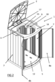
- FIG. 1 shows a waste bin 1 according to an embodiment of the invention.
- the waste bin 1 has a lid 2.
- the function of the lid 2 of waste bin 1 is to screen the content of the waste bin from external factors such as rain, insects and in order to keep unpleasant odours inside the waste bin.
- the lid contributes to the preservation of a clean and organized environment and also provides a visual barrier for the contained waste, this improving aesthetics.
- the lid 2 of waste bin 1 can be opened in different ways.
- the simplest mechanism is a manual lid opening, wherein the lid is connected to a base or frame of waste bin 1 only via one or more hinges and wherein the user opens the lid manually by taking hold of it and lifting it upward. This type of mechanism is often used in small domestic waste bins.
- a pedal control Another known way of opening the lid 2 of waste bin 1 is via a pedal control.
- Many waste bins for instance kitchen waste bins, are equipped with a pedal mechanism.
- the lid is opened by pressing down on the pedal, typically done with a foot.
- the pedal mechanism typically comprises a combination of levers and rods. This allows the waste bin to be opened without touching the lid with the hands, and is thus hygienic and convenient, especially when the user's hands are full.
- the touch control acts as a snap mechanism, wherein snapping the lid 2 downward opens a closing mechanism and thereby opens lid 2.
- the advantage hereof is that the lid will not open accidentally, and is still easily accessible.
- Lid 2 of waste bin 1 is most preferably provided with a sensor-based automation, which is further described below.
- the waste bin 1 comprises sensors which detect movement or presence. When movement or presence is detected close to the sensor, for instance by moving a hand or foot in the vicinity of the waste bin 1, the lid opens automatically. This way of opening the lid 2 also allows the bin to be opened without touching the lid with the hands, and is thus hygienic and convenient.
- Figure 1 shows a bottom plate 5 at the bottom of the waste bin.
- the bottom plate 5 is preferably an injection-moulded part from a hard plastic.
- the bottom plate 5 preferably has legs on its underside. The height of the legs is further preferably adjustable, for instance in that the legs are connected to the bottom plate 5 via a screw thread, such that the bottom plate 5 can be placed substantially horizontally on a ground surface, even when the ground surface is uneven.
- Bottom plate 5 preferably has on its upper side slots or grooves or protrusions or edges for positioning and/or attaching the upright side walls of the waste bin 1.
- Bottom plate 5 is preferably provided with an opening (not shown) so that water that finds its way into the waste bin, for instance during cleaning of the waste bin, is able to flow out of the bottom plate via the opening.
- Figure 1 shows or refers to several upright walls.
- Figure 1 thus refers to rear wall 6, the figure shows one of the side walls 7 and the figure also shows the front wall 8.
- These walls are preferably panels manufactured from plastic or aluminium or similar materials. These walls are more preferably constructed with extrusion elements or injection moulded elements.
- Figure 1 further shows an outer portion of the protective edge 14 which will be further described below.
- the rear wall 6 is preferably formed such that the waste bin 1 can be suspended from an upright structure, for instance against a wall.
- two handles 19 are further provided on the waste bin in order to simplify lifting and displacing of the waste bin.
- the handles 19 are preferably removable or collapsible, so that the handles do not prevent a waste bin 1 from being placed against a wall with its side or a plurality of waste bins from being placed against each other with their side walls.
- Figure 2 shows the waste bin 1 of figure 1 in an opened position. More specifically, in figure 2 both the lid 2 and the front wall are opened.
- the lid 2 is connected to the rear wall 6 of waste bin 1 via a hinge.
- a lever 17 Provided close to this hinge is a lever 17 which can push lid 2 upward in order to open lid 2. When the lever 17 is lowered, lid 2 will close due to the force of gravity.
- FIG. 2 shows a spraying mechanism 3 provided centrally against the rear wall 6 and directly under lid 2. It will be apparent that the spraying mechanism 3 can also be provided at other locations in the waste bin. As further elucidated below, it is advantageous to provide the spraying mechanism 3 directly under the lever 17, since the lid and the spraying mechanism 3 can hereby be operated by the same actuator.
- Figure 2 shows the protective edge 14 with the waste opening 15.
- This protective edge 14 is preferably removable, for instance by means of sliding or pivoting.
- Figure 2 shows the bottom plate 5 and two upright side walls 7.
- the front wall 8 is provided in two parts 8a and 8b, which are each connected pivotally to a side wall 7 so that the front wall 8 can be opened.
- the front wall can be formed integrally and can be connected pivotally to one of the side walls 7 or to the bottom plate 5.
- the front wall is removable in other manner, for instance pull-out or snap-out.
- the waste opening 15 is provided in the protective edge 14 for throwing waste into the waste bin. It will be described below how a bin bag can be installed in the waste bin 1.
- the waste opening 15 has dimensions and is positioned to be situated above an opening of a bin bag when the bin bag is installed in the waste bin.
- the dimensions of the waste opening 15 are selected on one hand to allow waste of a determined maximum size to pass and to ensure that waste is unable to find its way between the upright walls of the waste bin and the bin bag.
- the protective edge 14 will also form a protection for the bag grippers 9 with spring elements 10 and for the spraying mechanism 3.
- FIG. 2 shows a bag gripper 9.
- the bag gripper 9 is connected to upright walls of the waste bin, more specifically to the side wall 7. Only one bag gripper 9 is designated in the figure, but the skilled person will appreciate that a plurality of bag grippers 9 are provided at multiple locations on the upper side of waste bin 1.
- the bag gripper 9 is preferably positioned just below protective edge 14.
- Each bag gripper 9 is preferably provided on a spring element 10.
- the spring element 10 is configured to push the bag gripper 9 toward a periphery of the waste bin 1. At the same time, the spring element 10 allows the bag gripper 9 to be moved to a more central position of waste bin 1 by means of applying an external force.
- a further advantage of providing bag grippers 9 on spring elements 10 is that bin bags with an opening smaller than the peripheral opening of waste bin 1 can also be placed in the waste bin. In such a situation the spring elements 10 will not be able to push the bag grippers 9 completely to the periphery of the waste bin after the bag has been placed, but they will spread open the bin bag to the maximum extent. In other words, bin bags of different dimensions, more specifically different opening diameters, can be installed in the waste bin.
- the bag gripper 9 can be formed in different ways.
- the bag gripper 9 can thus be formed as a clamp between which the material of the bin bag is clampable.
- the bag gripper 9 can alternatively be formed as a hook behind which material of the bin bag can be hooked.
- the hook element does not take the form of a fish hook or similar hook, but rounded shapes are provided behind which an edge of a bin bag can be hung in order to thus hold the edge.
- the bag gripper 9, when it is shaped as a hook has a form similar to an edge of a standard bin-like waste receptacle. This is further shown in figure 5 .
- Figure 2 further shows a support plate 12 which is provided at the bottom of waste bin 1.
- the support plate 12 is provided on a support plate mounting element 13, shown in figure 3 , which allows the height of support plate 12 in waste bin 1 to be controlled.
- the support plate 12 preferably has a substantially flat upper side.
- Support plate 12 is preferably provided substantially horizontally in waste bin 1. In its lowest position the support plate 12 can lie on bottom plate 5. In any other position, support plate 12 will lie at a distance from bottom plate 5.
- the support plate can preferably be provided in the waste bin at a number of heights between a lowermost position where the support plate 12 lies on bottom plate 5 and an uppermost position where the support plate lies at at least one fifth of the overall height of waste bin 1, preferably at at least a quarter of the overall height of waste bin 1.
- Said number is preferably greater than 3, preferably greater than 5.
- FIG. 3 shows how the rear wall 6 and side wall 7 are provided in the bottom plate 5.
- Bottom plate 5 is preferably a plastic element manufactured by injection moulding.
- Bottom plate 5 has at the position of its periphery an edge and, inside this edge, protrusions, preferably elongate protrusions, to engage on and hold the rear wall 6 and side walls 7.
- the rear wall 6 and side walls 7 are preferably manufactured from aluminium panels which are formed by extrusion.
- Each of the rear wall 6 and side walls can be formed here by one or more aluminium panels.
- the number of different aluminium panels in one waste bin is preferably limited by reusing a determined panel in several walls.
- the aluminium panels are pressed downward into the bottom plate.
- the thus upright aluminium panels are held together by providing a top structure with the lid 2 at the top. This principle is known to the skilled person and requires no further elucidation.
- Figure 3 further shows an embodiment of the support plate mounting element 13.
- the support plate mounting element 13 comprises two upright brackets which are compatible with the support plate 12 so that support plate 12 can be mounted at multiple heights. This is illustrated with arrow 20.
- the skilled person will appreciate that alternative mechanisms can be provided in the waste bin to position the support plate 12 at different heights. Pins can for instance be provided in a series of holes in the upright walls 6, 7, on which pins the support plate 12 can rest, similar to pins which can be provided in a wardrobe for the purpose of placing a shelf.
- Figure 4 shows a preferred embodiment of a spraying mechanism 3.
- the spraying mechanism 3 is preferably provided at the top, centrally against the rear wall 6 of waste bin 1 and on the inner side of waste bin 1.
- the spraying mechanism 3 comprises a cleaning product 4, typically held in a canister or bottle or spray can.
- the cleaning product 4 can be dosed in waste bin 1 via a spray head 21.
- the spray head 21 can take the form of a nozzle (not shown) or the cleaning product 4 can be dosed to a predetermined location in the waste bin via a tube or hose.
- the spray head 21 can be active or passive, as known from spray cans for perfume and deodorant.
- a passive spray head 21 will allow passage of product when the head is pressed down, but the movement of the product is propelled elsewhere, for instance by propellant gas or another propelling mechanism.
- An active spray head 21 will pump product when the head is pressed down and will thus actively propel the product.
- the spray head 21 is pressed down by a cam 18 which is provided on an actuator 16.
- the actuator 16 is shown schematically in the figure, and the skilled person will be familiar with provision of for instance an electric motor with a cam 18 thereon, thus necessitating no further elucidation for this aspect.
- the actuator 16 is preferably an electric motor.
- the electric motor can be powered by a fixed power cable of the waste bin, so that the waste bin must be connected to a socket outlet or other electrical connection in order to function.
- a battery which powers the electric motor is alternatively provided in the waste bin.
- the head of the electric motor is connected to the cam 18 such that, when the electric motor runs in a first direction, the cam 18 is rotated downward and, when the electric motor runs in a second direction, the cam 18 is rotated upward.
- the lever 17 is positioned between the cam 18 of actuator 16 on one side and the lid 2 on the other.
- the lever 17 is also illustrated in figure 2 , and the skilled person will appreciate how pushing upward of lever 17 results in opening of lid 2.
- Lever 17 is preferably connected fixedly to lid 2 and not to cam 18. This has two advantages. The first advantage is that cam 18 is completely free to move downward for the purpose of pressing down spray head 21. This downward movement has no effect on the lever 17, and nor therefore on the lid 2. A second advantage is that lid 2 can also be lifted manually, whereby lever 17 is also lifted upward without this influencing or affecting cam 18. In order to achieve the same two advantages, it is alternatively possible for lever 17 to be connected to cam 18 but not to lid 2. In each case the lever 17 is preferably guided between lid 2 and cam 18 by a guide bush in order to maintain the position of lever 17.
- the spraying mechanism, the actuator and the lever are preferably screened at least partially by a screen 22. Removal of screen 22 allows the cleaning product 4 to be topped up and/or replaced and allows other maintenance and/or replacement work to be carried out on the above described and shown mechanisms.
- the screen 22 further provides for a centralization of the tube and spray head which lies at right angles to the front side of the shield 22.
- the spray head preferably has a specific form with a long nose in order to ensure that the head always lies in line with the tube.
- the shield 22 is further preferably mounted pivotally on the housing of the actuator, wherein the hinge (not shown) is located at the top of the shield 22 in order to allow shield 22 to pivot upward.
- the electronic circuit with the clock and the sensor are not shown in the figures because the position and form of these components are not relevant. The functions of these components were described above in a manner allowing a skilled person to realize them. The skilled person will thus appreciate that, depending on the type, the sensor can be provided at different locations in the inner side and/or on the outer side of the waste bin in order to detect a predetermined movement or presence.
- the mechanism shown in figure 4 with inter alia the spraying mechanism 3, the actuator 16 and the lever 17, can be sold separately so as to be built into existing waste bins with a hinged lid, wherein the existing waste bin can on one hand be cleaned and can on the other hand be provided with an automatic opener for the lid.
- FIG. 5 shows a preferred embodiment of the bag grippers 9 and spring elements 10.
- Each bag gripper 9 is connected via a spring element 10 to a side wall of waste bin 1.
- two spring element 10 are in each case formed by a leaf spring.
- Each of the ends carries a bag gripper 9.
- This embodiment can be manufactured in simple manner and installed inexpensively. Different types of bag gripper 9 can be connected to the spring elements 10.
Landscapes
- Engineering & Computer Science (AREA)
- Mechanical Engineering (AREA)
- Control And Other Processes For Unpacking Of Materials (AREA)
- Refuse Receptacles (AREA)
Abstract
Waste bin (1) for enclosing a bin bag, wherein the waste bin (1) has a lid (2) and has a spraying mechanism (3) which is adapted to spray a cleaning product (4) in the waste bin when the lid is in a closed position.
Description
- The invention relates to a waste bin for enclosing a bin bag. A waste bin, also known as a rubbish bin, dustbin or trash can, is a container designed specifically for collecting and storing waste and other unwanted material. Waste bins are usually made of durable material such as plastic, metal or sometimes even wood, depending on their intended use and the environment in which they are placed.
- Waste bins exist in different sizes and shapes, varying from small pedal bins for domestic use to large industrial containers which are placed in public locations, offices, schools, parks and other locations.
- A typical waste bin has a lid which can vary from a simple flap, a sliding lid to a lid with a pedal or a sensor for handsfree operation. This lid helps trap odours and prevents vermin such as flies and mice from being able to reach the waste.
- Waste bins play an essential part in promoting a clean and hygienic environment, since they enable people to discard their waste in an organized and responsible manner. Separating waste in the correct way and depositing it in the correct bin enables recycling and waste processing to be carried out more efficiently, which is favourable for the environment.
- It is important to empty and clean waste bins regularly in order to prevent them from overflowing or spreading unpleasant odours. This contributes to tidiness being maintained and enhances a healthy living environment for everyone.
- A bin bag, also known as bin liner or trash bag, is a flexible, typically watertight bag designed specifically for keeping and collecting waste and other unwanted material therein. Bin bags are commonly used in households, offices, schools and other environments where waste is produced.
- Bin bags are usually made of strong plastic, such as polyethylene, and are available in different sizes and colours. The size of the bin bag can vary depending on requirements and use.
- Bin bags have an open upper side, making it easy to deposit waste therein. Some bin bags have a drawstring closure or a knot on the upper side for closing off the content and to prevent odours from escaping.
- The use of bin bags is a convenient and hygienic way of collecting waste and transporting it to the waste bins or containers. They help keep the inside of waste bins clean and facilitate the process of waste removal.
- A bin bag and a waste bin are usually used together in order to make waste collection and management easier and more hygienic. The bin bag is placed in the waste bin and functions as a barrier between the waste and the inner side of the waste bin. When waste is thrown into the waste bin, this waste will thus not come into direct contact with the inner side of the waste bin, this keeping the waste bin clean. When it is deposited into the waste bin with bin bag, waste does come to lie directly in the bin bag placed in the waste bin.
- When the bin bag is full, or when it is time to remove the waste, it can be easily removed from the waste bin for further transport and/or processing. This makes emptying and cleaning of the waste bin a simple task.
- Bin bags having dimensions and a shape adapted specifically to a specific waste bin are sold in practice. In other words, the manufacturer of the waste bin also sells the bin bag as a refill, so stimulating repeated purchases once a one-time sale of the waste bin has been realized.
- Drawbacks of existing waste bins with bin bags are that the waste bin is typically not adapted to comprise different types and dimensions of bin bag. The limitation of odour nuisance and vermin such as flies and wasps to an acceptable level further remains sub-optimal, even when a lid is provided on the waste bin.
- It is an object of the invention to improve the hygiene of a waste bin.
- For this purpose the invention provides a waste bin for enclosing a bin bag, wherein the waste bin has a lid and has a spraying mechanism which is adapted to spray a cleaning product in the waste bin when the lid is in a closed position.
- A spraying mechanism in the waste bin, provided to spray a cleaning product in the waste bin when the lid is closed, enables hygiene to be improved in different ways, optionally combined. It is thus possible to exterminate vermin such as flies, wasps and their larvae by selecting a cleaning product having this effect. Such a cleaning product can be dosed in the closed waste bin by means of the spraying mechanism. An advantage is that the dosage of such a cleaning product can be adjusted such that the exterminating effect is achieved only within the volume of the closed bin. This means that, were the waste bin to be opened and the cleaning product to find its way into the surrounding area, the dosage becomes so low owing to the greater volume of the surrounding area that it has no noticeable effect in the surrounding area. Improved hygiene can thus be achieved in a safe manner. It is also possible to dose odour-absorbing or odour-compensating cleaning products in the waste bin in order to minimize the spreading of unpleasant odours when the waste bin is opened.
- The waste bin preferably further comprises a bottom plate on which a rear wall and two side walls are provided, wherein the lid is connected pivotally to one of the rear wall and two side walls, preferably to the rear wall, so that the lid is pivotable between an upright position and a lying position, the waste bin further comprising a front wall which is connected pivotally to at least one of the side walls so that the front wall is pivotable between an open and a closed position, all this such that a front side of the waste bin is wholly accessible when the lid is in the upright position and the front wall is in the open position.
- In order to optimize manufacture and transport of the waste bin, the waste bin is provided with a bottom plate, rear wall, side walls, lid and front wall. These parts can be packaged, stored and transported to an end user of the waste bin separately of each other, optionally together. This increases the efficiency of the logistics chain. In assembled state the rear wall and side walls are provided fixedly on the bottom plate so as to form the fixed part of the waste bin. Both the lid and the front wall are connected pivotally to the fixed part of the waste bin. Because both the lid and the front wall can be tilted or rotated, the whole front side of the waste bin can be opened in order to remove a full bin bag from the waste bin in very simple manner and to place a new bin bag in the waste bin. Because the bin bag need no longer be lifted out of the waste bin along the upper side, the risk of tearing of the bin bag is also greatly reduced. This increases the user comfort during switching of bin bags in the waste bin.
- The rear wall and two side walls preferably comprise at least three, preferably four bag grippers for holding the bin bag in the waste bin. The at least three bag grippers are further preferably each provided on a spring element, such that each bag gripper is pushed toward a periphery of the waste bin by the spring element and such that the bag gripper is movable at least partially toward a centre of the waste bin in order to enable bin bags of different dimensions to be held and, in held state, be held open in the waste bin in simple manner.
- Bag grippers, particularly when located on a spring element, allow different sizes, shapes and types of bin bag to be installed in the waste bin in very simple manner. This in contrast to many waste bins, which require a specific type of bag and where only this specific bag can be secured correctly and firmly in the waste bin owing to its dimensions and shape. The gripper on the spring element has the result that the grippers can be moved to a more central position in the waste bin when installing the bin bag. This makes it simple to grip a bin bag with an opening of a determined diameter with its edge in or around the grippers. After the edge of the bin bag has been gripped, the spring elements can be released so that the grippers are pushed toward the periphery of the waste bin by the spring elements. This opens the bin bag widely in order to maximize the opening within the boundaries of the waste bin. A bin bag can also be installed in the waste bin when the bin bag has a diameter smaller than that of the waste bin. In that case the spring elements will stretch the opening of the bin bag to its maximum, and will not reach the periphery of the waste bin. In this way the bin bag is also held open at all times so that waste that is thrown into the waste bin will always come to lie in the bin bag correctly.
- Preferably, two times two bag grippers are connected to opposite ends of a leaf spring and a central zone of each leaf spring is mounted fixedly against one of the rear wall and two side walls, such that in unloaded state the bag grippers are situated substantially close to the periphery of the waste bin. Providing a leaf spring with a bag gripper at opposite ends is very simple and inexpensive. The leaf spring can be connected centrally to the fixed part of the waste bin so that the two bag grippers are both movable from a more central position in the waste bin to a periphery of the waste bin.
- A support plate is preferably provided in the waste bin for the purpose of supporting an underside of the bin bag, wherein the waste bin further has a support plate mounting element which is provided to mount the support plate in the waste bin at different heights.
- By providing a support plate which can be mounted in the waste bin at different heights a mechanism is provided for supporting bin bags with different dimensions in the waste bin at the bottom, so that the weight of the bin bag with the waste does not end up suspended from the bag grippers. This is a great advantage when designing and using the bag grippers, this because the function of the bag grippers is limited to positioning the upper edge while the support plate provides for support of the weight of the bin bag with the waste.
- The waste bin preferably has a protective edge which has a substantially central waste opening and which is located substantially directly under the lid when the lid is in the lying position.
- The protective edge with the waste opening has the result that when waste is thrown into the waste bin, this waste comes to lie in the bin bag. The bin bag is held under the protective edge by the bag grippers. The at least three, preferably four bag grippers are preferably provided under the protective edge. As described above, it is possible to install bin bags which are smaller than the waste bin in the waste bin. With the bag grippers the bin bag is still spread open at the position of the lid. With the support plate the bin bag is still supported correctly at the position of its underside. Owing to the protective edge with waste opening, waste which is thrown into the waste bin comes to lie in the bin bag and not between the upright walls of the waste bin and the bin bag.
- The protective edge is preferably connected removably to the waste bin. The protective edge is alternatively connected pivotally to the waste bin. Hereby, it remains possible to open the whole front side of the waste bin in order to replace the bin bag.
- Preferably, the waste bin comprises a sensor for detecting an activity in the vicinity of the waste bin and the waste bin comprises an actuator which is connected operatively to the sensor and which is connected mechanically to the lid for the purpose of pivoting the lid upward following a predetermined signal from the sensor.
- Providing a sensor and an actuator which is able to open the lid renders touching the waste bin unnecessary when depositing waste into the waste bin. This greatly improves hygiene. In order to deposit waste into the waste bin a movement can be performed near the waste bin, at a predetermined distance from the waste bin or within a predetermined area around the waste bin, this in order to trigger the sensor. The sensor sends a signal to the actuator, which pivots the lid upward and holds it up for a preset amount of time. The actuator is preferably connected to the lid via a lever mechanism. The lever mechanism facilitates the upward pivoting of the lid and allows for a first movement of an actuator to be converted into a pivoting of the lid, wherein forces and magnitudes of movements can be mutually adapted and balanced.
- The actuator is preferably provided to perform two different movements, wherein a first movement operates the lever mechanism and a second movement activates the spraying mechanism. This makes the actuator multifunctional. This improves the efficiency of the waste bin and reduces the costs of the waste bin. The space required for incorporating the actuator also remains limited. Maintenance is further also simple, and the number of spare parts is reduced by the dual use of the actuator.
- The actuator is preferably a motor with a cam which is positioned to push against the lever mechanism during an upward rotation of the cam in order to pivot the lid upward, and to push against a spray head of the spraying mechanism during a downward rotation of the cam in order to spray the cleaning product in the waste bin. This shows how the same actuator, a motor, can perform two functions since the motor can be driven in two directions.
- The waste bin preferably further comprises an electronic circuit with a clock for controlling predetermined actions periodically. The electronic circuit is preferably configured to activate the spraying mechanism after the lid has been closed by the actuator, and to activate the spraying mechanism every time the lid has remained unopened for a predetermined amount of time. The electronic circuit allows the functionality and operation of the waste bin to be monitored and controlled. Several additional functions for influencing the operation of the waste bin can be envisaged. The waste bin could thus be set to open only during certain hours, for instance the opening hours of a shop. Another possible setting is for cleaning agent to be dosed in the waste bin only within a determined period, for instance at night.
- The invention will now be further described on the basis of a plurality of exemplary embodiments shown in the drawings.
- In the drawing:
-
figure 1 shows a waste bin according to a preferred embodiment of the invention in a perspective view and in a closed position; -
figure 2 shows a waste bin according to the embodiment offigure 1 in a perspective view and in an open position; -
figure 3 shows several parts of the waste bin offigure 1 ; -
figure 4 shows a spraying mechanism suitable for a waste bin according to a preferred embodiment of the invention; and -
figure 5 shows a leaf spring with bag grippers according to a preferred embodiment of the invention. - The same or similar elements are designated in the drawing with the same reference numerals.
-
Figure 1 shows awaste bin 1 according to an embodiment of the invention. Thewaste bin 1 has alid 2. The function of thelid 2 ofwaste bin 1 is to screen the content of the waste bin from external factors such as rain, insects and in order to keep unpleasant odours inside the waste bin. The lid contributes to the preservation of a clean and organized environment and also provides a visual barrier for the contained waste, this improving aesthetics. - The
lid 2 ofwaste bin 1 can be opened in different ways. The simplest mechanism is a manual lid opening, wherein the lid is connected to a base or frame ofwaste bin 1 only via one or more hinges and wherein the user opens the lid manually by taking hold of it and lifting it upward. This type of mechanism is often used in small domestic waste bins. - Another known way of opening the
lid 2 ofwaste bin 1 is via a pedal control. Many waste bins, for instance kitchen waste bins, are equipped with a pedal mechanism. The lid is opened by pressing down on the pedal, typically done with a foot. For this purpose the pedal mechanism typically comprises a combination of levers and rods. This allows the waste bin to be opened without touching the lid with the hands, and is thus hygienic and convenient, especially when the user's hands are full. - Another known way of opening the
lid 2 ofwaste bin 1 is via a mechanical touch control. The touch control acts as a snap mechanism, wherein snapping thelid 2 downward opens a closing mechanism and thereby openslid 2. The advantage hereof is that the lid will not open accidentally, and is still easily accessible. -
Lid 2 ofwaste bin 1 is most preferably provided with a sensor-based automation, which is further described below. Stated briefly, thewaste bin 1 comprises sensors which detect movement or presence. When movement or presence is detected close to the sensor, for instance by moving a hand or foot in the vicinity of thewaste bin 1, the lid opens automatically. This way of opening thelid 2 also allows the bin to be opened without touching the lid with the hands, and is thus hygienic and convenient. -
Figure 1 shows abottom plate 5 at the bottom of the waste bin. Thebottom plate 5 is preferably an injection-moulded part from a hard plastic. Thebottom plate 5 preferably has legs on its underside. The height of the legs is further preferably adjustable, for instance in that the legs are connected to thebottom plate 5 via a screw thread, such that thebottom plate 5 can be placed substantially horizontally on a ground surface, even when the ground surface is uneven.Bottom plate 5 preferably has on its upper side slots or grooves or protrusions or edges for positioning and/or attaching the upright side walls of thewaste bin 1.Bottom plate 5 is preferably provided with an opening (not shown) so that water that finds its way into the waste bin, for instance during cleaning of the waste bin, is able to flow out of the bottom plate via the opening. -
Figure 1 shows or refers to several upright walls.Figure 1 thus refers torear wall 6, the figure shows one of theside walls 7 and the figure also shows thefront wall 8. These walls are preferably panels manufactured from plastic or aluminium or similar materials. These walls are more preferably constructed with extrusion elements or injection moulded elements.Figure 1 further shows an outer portion of theprotective edge 14 which will be further described below. Therear wall 6 is preferably formed such that thewaste bin 1 can be suspended from an upright structure, for instance against a wall. - In
figure 1 twohandles 19 are further provided on the waste bin in order to simplify lifting and displacing of the waste bin. Thehandles 19 are preferably removable or collapsible, so that the handles do not prevent awaste bin 1 from being placed against a wall with its side or a plurality of waste bins from being placed against each other with their side walls. -
Figure 2 shows thewaste bin 1 offigure 1 in an opened position. More specifically, infigure 2 both thelid 2 and the front wall are opened. Thelid 2 is connected to therear wall 6 ofwaste bin 1 via a hinge. Provided close to this hinge is alever 17 which can pushlid 2 upward in order to openlid 2. When thelever 17 is lowered,lid 2 will close due to the force of gravity. -
Figure 2 shows aspraying mechanism 3 provided centrally against therear wall 6 and directly underlid 2. It will be apparent that thespraying mechanism 3 can also be provided at other locations in the waste bin. As further elucidated below, it is advantageous to provide thespraying mechanism 3 directly under thelever 17, since the lid and thespraying mechanism 3 can hereby be operated by the same actuator. -
Figure 2 shows theprotective edge 14 with thewaste opening 15. Thisprotective edge 14 is preferably removable, for instance by means of sliding or pivoting.Figure 2 shows thebottom plate 5 and twoupright side walls 7. Infigure 2 thefront wall 8 is provided in twoparts side wall 7 so that thefront wall 8 can be opened. The skilled person will appreciate that when theprotective edge 14 is removed, the whole front side ofwaste bin 1 is open whenfront wall 8 is opened andlid 2 is opened. This allows a bin bag to be placed in the waste bin and to be removed from the waste bin in extremely simple manner. The skilled person will appreciate that, in an alternative embodiment, the front wall can be formed integrally and can be connected pivotally to one of theside walls 7 or to thebottom plate 5. As further alternative, the front wall is removable in other manner, for instance pull-out or snap-out. - The
waste opening 15 is provided in theprotective edge 14 for throwing waste into the waste bin. It will be described below how a bin bag can be installed in thewaste bin 1. Thewaste opening 15 has dimensions and is positioned to be situated above an opening of a bin bag when the bin bag is installed in the waste bin. The dimensions of thewaste opening 15 are selected on one hand to allow waste of a determined maximum size to pass and to ensure that waste is unable to find its way between the upright walls of the waste bin and the bin bag. Theprotective edge 14 will also form a protection for thebag grippers 9 withspring elements 10 and for thespraying mechanism 3. -
Figure 2 shows abag gripper 9. Thebag gripper 9 is connected to upright walls of the waste bin, more specifically to theside wall 7. Only onebag gripper 9 is designated in the figure, but the skilled person will appreciate that a plurality ofbag grippers 9 are provided at multiple locations on the upper side ofwaste bin 1. Thebag gripper 9 is preferably positioned just belowprotective edge 14. Eachbag gripper 9 is preferably provided on aspring element 10. Thespring element 10 is configured to push thebag gripper 9 toward a periphery of thewaste bin 1. At the same time, thespring element 10 allows thebag gripper 9 to be moved to a more central position ofwaste bin 1 by means of applying an external force. When a plurality ofbag grippers 9 is placed onsuch spring elements 10, thebag grippers 9 can thus be moved toward each other in order to simplify engaging and releasing of a bin bag. The skilled person will understand this mechanism, and it therefore requires no further elucidation. A further advantage of providingbag grippers 9 onspring elements 10 is that bin bags with an opening smaller than the peripheral opening ofwaste bin 1 can also be placed in the waste bin. In such a situation thespring elements 10 will not be able to push thebag grippers 9 completely to the periphery of the waste bin after the bag has been placed, but they will spread open the bin bag to the maximum extent. In other words, bin bags of different dimensions, more specifically different opening diameters, can be installed in the waste bin. - The
bag gripper 9 can be formed in different ways. Thebag gripper 9 can thus be formed as a clamp between which the material of the bin bag is clampable. Thebag gripper 9 can alternatively be formed as a hook behind which material of the bin bag can be hooked. The skilled person will appreciate here that, in order to clamp a bin bag with a hook, the hook element does not take the form of a fish hook or similar hook, but rounded shapes are provided behind which an edge of a bin bag can be hung in order to thus hold the edge. In this way thebag gripper 9, when it is shaped as a hook, has a form similar to an edge of a standard bin-like waste receptacle. This is further shown infigure 5 . -
Figure 2 further shows asupport plate 12 which is provided at the bottom ofwaste bin 1. Thesupport plate 12 is provided on a supportplate mounting element 13, shown infigure 3 , which allows the height ofsupport plate 12 inwaste bin 1 to be controlled. Thesupport plate 12 preferably has a substantially flat upper side.Support plate 12 is preferably provided substantially horizontally inwaste bin 1. In its lowest position thesupport plate 12 can lie onbottom plate 5. In any other position,support plate 12 will lie at a distance frombottom plate 5. The support plate can preferably be provided in the waste bin at a number of heights between a lowermost position where thesupport plate 12 lies onbottom plate 5 and an uppermost position where the support plate lies at at least one fifth of the overall height ofwaste bin 1, preferably at at least a quarter of the overall height ofwaste bin 1. Said number is preferably greater than 3, preferably greater than 5. Providing such asupport plate 12 allows bin bags with different dimensions, more specifically with different heights, to be placed inwaste bin 1, wherein thesupport plate 12 can be positioned to support the bin bag in question at the bottom when the bin bag in question is held with its upper edge in thebag grippers 9. An advantage hereof is that the weight of the waste being thrown into the bin bag need not be carried wholly bybag grippers 9, enabling them to be manufactured considerably more flexibly and simply. The bin bag need also be considerably less strong since the weight of the waste in the bin bag, when the bin bag is in the waste bin, is carried and supported largely by thesupport plate 12. -
Figure 3 shows how therear wall 6 andside wall 7 are provided in thebottom plate 5.Bottom plate 5 is preferably a plastic element manufactured by injection moulding.Bottom plate 5 has at the position of its periphery an edge and, inside this edge, protrusions, preferably elongate protrusions, to engage on and hold therear wall 6 andside walls 7. Therear wall 6 andside walls 7 are preferably manufactured from aluminium panels which are formed by extrusion. Each of therear wall 6 and side walls can be formed here by one or more aluminium panels. The number of different aluminium panels in one waste bin is preferably limited by reusing a determined panel in several walls. During assembly ofwaste bin 1 the aluminium panels are pressed downward into the bottom plate. The thus upright aluminium panels are held together by providing a top structure with thelid 2 at the top. This principle is known to the skilled person and requires no further elucidation. -
Figure 3 further shows an embodiment of the supportplate mounting element 13. In the shown embodiment the supportplate mounting element 13 comprises two upright brackets which are compatible with thesupport plate 12 so thatsupport plate 12 can be mounted at multiple heights. This is illustrated witharrow 20. The skilled person will appreciate that alternative mechanisms can be provided in the waste bin to position thesupport plate 12 at different heights. Pins can for instance be provided in a series of holes in theupright walls support plate 12 can rest, similar to pins which can be provided in a wardrobe for the purpose of placing a shelf. -
Figure 4 shows a preferred embodiment of aspraying mechanism 3. As described above and shown infigure 2 , thespraying mechanism 3 is preferably provided at the top, centrally against therear wall 6 ofwaste bin 1 and on the inner side ofwaste bin 1. Thespraying mechanism 3 comprises acleaning product 4, typically held in a canister or bottle or spray can. The cleaningproduct 4 can be dosed inwaste bin 1 via aspray head 21. For this purpose thespray head 21 can take the form of a nozzle (not shown) or thecleaning product 4 can be dosed to a predetermined location in the waste bin via a tube or hose. - The
spray head 21 can be active or passive, as known from spray cans for perfume and deodorant. Apassive spray head 21 will allow passage of product when the head is pressed down, but the movement of the product is propelled elsewhere, for instance by propellant gas or another propelling mechanism. Anactive spray head 21 will pump product when the head is pressed down and will thus actively propel the product. - The
spray head 21 is pressed down by acam 18 which is provided on anactuator 16. Theactuator 16 is shown schematically in the figure, and the skilled person will be familiar with provision of for instance an electric motor with acam 18 thereon, thus necessitating no further elucidation for this aspect. Theactuator 16 is preferably an electric motor. The electric motor can be powered by a fixed power cable of the waste bin, so that the waste bin must be connected to a socket outlet or other electrical connection in order to function. A battery which powers the electric motor is alternatively provided in the waste bin. The head of the electric motor is connected to thecam 18 such that, when the electric motor runs in a first direction, thecam 18 is rotated downward and, when the electric motor runs in a second direction, thecam 18 is rotated upward. When the cam is positioned above thespray head 21, the downward rotation of the cam will result inspray head 21 being pressed down in order to thus spray cleaningproduct 4. When the cam is provided under alever 17, the upward rotation of the cam will result in opening of thelid 2. In this way one electric motor can control two functions inwaste bin 1 separately of each other. It will be apparent that the electric motor cannot perform the two functions simultaneously, which is however not necessary or even desirable. This configuration prevents that cleaning product can be sprayed in the waste bin whilelid 2 is open, this adding some additional safety to this configuration. - The
lever 17 is positioned between thecam 18 ofactuator 16 on one side and thelid 2 on the other. Thelever 17 is also illustrated infigure 2 , and the skilled person will appreciate how pushing upward oflever 17 results in opening oflid 2.Lever 17 is preferably connected fixedly tolid 2 and not tocam 18. This has two advantages. The first advantage is thatcam 18 is completely free to move downward for the purpose of pressing downspray head 21. This downward movement has no effect on thelever 17, and nor therefore on thelid 2. A second advantage is thatlid 2 can also be lifted manually, wherebylever 17 is also lifted upward without this influencing or affectingcam 18. In order to achieve the same two advantages, it is alternatively possible forlever 17 to be connected tocam 18 but not tolid 2. In each case thelever 17 is preferably guided betweenlid 2 andcam 18 by a guide bush in order to maintain the position oflever 17. - The spraying mechanism, the actuator and the lever are preferably screened at least partially by a
screen 22. Removal ofscreen 22 allows the cleaningproduct 4 to be topped up and/or replaced and allows other maintenance and/or replacement work to be carried out on the above described and shown mechanisms. Thescreen 22 further provides for a centralization of the tube and spray head which lies at right angles to the front side of theshield 22. The spray head preferably has a specific form with a long nose in order to ensure that the head always lies in line with the tube. Theshield 22 is further preferably mounted pivotally on the housing of the actuator, wherein the hinge (not shown) is located at the top of theshield 22 in order to allowshield 22 to pivot upward. - The electronic circuit with the clock and the sensor are not shown in the figures because the position and form of these components are not relevant. The functions of these components were described above in a manner allowing a skilled person to realize them. The skilled person will thus appreciate that, depending on the type, the sensor can be provided at different locations in the inner side and/or on the outer side of the waste bin in order to detect a predetermined movement or presence.
- The mechanism shown in
figure 4 , with inter alia thespraying mechanism 3, theactuator 16 and thelever 17, can be sold separately so as to be built into existing waste bins with a hinged lid, wherein the existing waste bin can on one hand be cleaned and can on the other hand be provided with an automatic opener for the lid. -
Figure 5 shows a preferred embodiment of thebag grippers 9 andspring elements 10. Eachbag gripper 9 is connected via aspring element 10 to a side wall ofwaste bin 1. In the embodiment offigure 5 twospring element 10 are in each case formed by a leaf spring. By providing the leaf spring with a central zone which is adapted to be connected to the side wall ofwaste bin 1 both ends of the leaf spring, on either side of the central zone, function asspring element 10 independently of each other. Each of the ends carries abag gripper 9. This embodiment can be manufactured in simple manner and installed inexpensively. Different types ofbag gripper 9 can be connected to thespring elements 10. - The above described exemplary embodiments serve solely for the purpose of illustrating the invention and are not intended to limit the scope of protection.
Claims (15)
- Waste bin for enclosing a bin bag, wherein the waste bin has a lid and has a spraying mechanism which is adapted to spray a cleaning product in the waste bin when the lid is in a closed position.
- Waste bin according to the foregoing claim, further comprising a bottom plate on which a rear wall and two side walls are provided, wherein the lid is connected pivotally to one of the rear wall and two side walls, preferably to the rear wall, so that the lid is pivotable between an upright position and a lying position, the waste bin further comprising a front wall which is connected pivotally to at least one of the side walls so that the front wall is pivotable between an open and a closed position, all this such that a front side of the waste bin is wholly accessible when the lid is in the upright position and the front wall is in the open position.
- Waste bin according to the foregoing claim, wherein the rear wall and two side walls comprise at least three, preferably four bag grippers for holding the bin bag in the waste bin.
- Waste bin according to the foregoing claim, wherein the at least three bag grippers are each provided on a spring element, such that each bag gripper is pushed toward a periphery of the waste bin by the spring element and such that the bag gripper is movable at least partially toward a centre of the waste bin in order to enable bin bags of different dimensions to be held and, in held state, be held open in the waste bin in simple manner.
- Waste bin according to the foregoing claim, wherein two times two bag grippers are connected to opposite ends of a leaf spring and wherein a central zone of each leaf spring is mounted fixedly against one of the rear wall and two side walls, such that in unloaded state the bag grippers are situated substantially close to the periphery of the waste bin.
- Waste bin according to any one of the foregoing claims, wherein a support plate is provided in the waste bin for the purpose of supporting an underside of the bin bag, wherein the waste bin further has a support plate mounting element which is provided to mount the support plate in the waste bin at different heights.
- Waste bin according to any one of the foregoing claims, wherein the waste bin has a protective edge which has a substantially central waste opening and which is located substantially directly under the lid when the lid is in the lying position.
- Waste bin according to the foregoing claim and any one of the claims 3-5, wherein the at least three, preferably four bag grippers are provided under the protective edge.
- Waste bin according to any one of the claims 7-8, wherein the protective edge is connected removably to the waste bin.
- Waste bin according to any one of the foregoing claims, wherein the waste bin comprises a sensor for detecting an activity in the vicinity of the waste bin and wherein the waste bin comprises an actuator which is connected operatively to the sensor and which is connected mechanically to the lid for the purpose of pivoting the lid upward following a predetermined signal from the sensor.
- Waste bin according to the foregoing claim, wherein the actuator is connected to the lid via a lever mechanism.
- Waste bin according to any one of the claims 10-11, wherein the actuator is provided to perform two different movements, wherein a first movement operates the lever mechanism and a second movement activates the spraying mechanism.
- Waste bin according to the foregoing claim, wherein the actuator is a motor with a cam which is positioned to push against the lever mechanism during an upward rotation of the cam in order to pivot the lid upward, and to push against a spray head of the spraying mechanism during a downward rotation of the cam in order to spray the cleaning product in the waste bin.
- Waste bin according to any one of the claims 10-13, wherein the waste bin further comprises an electronic circuit with a clock for controlling predetermined actions periodically.
- Waste bin according to claim 14 and claim 12 or 13, wherein the electronic circuit is configured to activate the spraying mechanism after the lid has been closed by the actuator, and to activate the spraying mechanism every time the lid has remained unopened for a predetermined amount of time.
Applications Claiming Priority (1)
| Application Number | Priority Date | Filing Date | Title |
|---|---|---|---|
| BE20236089A BE1032305B1 (en) | 2023-12-29 | 2023-12-29 | Bin |
Publications (1)
| Publication Number | Publication Date |
|---|---|
| EP4578797A1 true EP4578797A1 (en) | 2025-07-02 |
Family
ID=89474705
Family Applications (1)
| Application Number | Title | Priority Date | Filing Date |
|---|---|---|---|
| EP24223193.4A Pending EP4578797A1 (en) | 2023-12-29 | 2024-12-24 | Bin |
Country Status (2)
| Country | Link |
|---|---|
| EP (1) | EP4578797A1 (en) |
| BE (1) | BE1032305B1 (en) |
Citations (5)
| Publication number | Priority date | Publication date | Assignee | Title |
|---|---|---|---|---|
| GB2326814A (en) * | 1997-06-30 | 1999-01-06 | Richard John Rand | Ventilation of material, such as refuse, in a container |
| US20170313503A1 (en) * | 2016-04-27 | 2017-11-02 | Busch Systems International Inc. | Container system with supportable liner |
| KR101871440B1 (en) * | 2018-01-09 | 2018-06-26 | 일월정밀 주식회사 | Food Waste Collection Device |
| US20200207544A1 (en) * | 2019-01-02 | 2020-07-02 | Forever Gifts, Inc. | Touchless receptacle with active fragrancing |
| US20200391940A1 (en) * | 2019-06-13 | 2020-12-17 | Nine Stars Group (U.S.A.) Inc. | Artificial Intelligent Trash Container with Sanitary and Health Control Arrangement |
-
2023
- 2023-12-29 BE BE20236089A patent/BE1032305B1/en active IP Right Grant
-
2024
- 2024-12-24 EP EP24223193.4A patent/EP4578797A1/en active Pending
Patent Citations (5)
| Publication number | Priority date | Publication date | Assignee | Title |
|---|---|---|---|---|
| GB2326814A (en) * | 1997-06-30 | 1999-01-06 | Richard John Rand | Ventilation of material, such as refuse, in a container |
| US20170313503A1 (en) * | 2016-04-27 | 2017-11-02 | Busch Systems International Inc. | Container system with supportable liner |
| KR101871440B1 (en) * | 2018-01-09 | 2018-06-26 | 일월정밀 주식회사 | Food Waste Collection Device |
| US20200207544A1 (en) * | 2019-01-02 | 2020-07-02 | Forever Gifts, Inc. | Touchless receptacle with active fragrancing |
| US20200391940A1 (en) * | 2019-06-13 | 2020-12-17 | Nine Stars Group (U.S.A.) Inc. | Artificial Intelligent Trash Container with Sanitary and Health Control Arrangement |
Also Published As
| Publication number | Publication date |
|---|---|
| BE1032305A1 (en) | 2025-07-31 |
| BE1032305B1 (en) | 2025-08-12 |
Similar Documents
| Publication | Publication Date | Title |
|---|---|---|
| US10723549B2 (en) | Trash cans with adaptive dampening | |
| US5090785A (en) | Multi-compartment container | |
| US20150351378A1 (en) | Self emptying rat trap for dumpsters and residential waste carts | |
| EP2107014A1 (en) | Compacting bin | |
| US5398374A (en) | Handle assembly for trash bin | |
| CN106185121B (en) | A kind of Odourproof refuse receptacle | |
| EP1904386A1 (en) | Automated insect deterrent pump spray applicator | |
| US20030183633A1 (en) | Container lid lifting device | |
| US20060169214A1 (en) | Animal waste receptacle | |
| US11884484B2 (en) | Bin aid | |
| BE1032305B1 (en) | Bin | |
| KR20120016391A (en) | Recyclable Separate Collection Mobile Puzzle Bins | |
| EP2768748B1 (en) | Vented receptacle for storing a plurality of waste types | |
| US11097894B2 (en) | Knee operated and/or motor operated waste bin | |
| JP2025524781A (en) | Sanitary device for trash can lids | |
| CN111017430A (en) | Two kinds of novel garbage cans | |
| US20160159572A1 (en) | Recycling and Garbage Chute Assembly | |
| ZA200501205B (en) | Waste disposal mechanism | |
| KR200411612Y1 (en) | Food waste bin with scaffolding and fully open lid | |
| CN205327916U (en) | Intelligent garbage bin | |
| KR20160132235A (en) | Infection prevention wastebasket | |
| CN216862523U (en) | Novel garbage can | |
| CA3147117C (en) | Bin aid | |
| KR200419036Y1 (en) | Food waste bin with fully open lid | |
| WO2012139585A1 (en) | Trap for rodents |
Legal Events
| Date | Code | Title | Description |
|---|---|---|---|
| PUAI | Public reference made under article 153(3) epc to a published international application that has entered the european phase |
Free format text: ORIGINAL CODE: 0009012 |
|
| STAA | Information on the status of an ep patent application or granted ep patent |
Free format text: STATUS: THE APPLICATION HAS BEEN PUBLISHED |
|
| AK | Designated contracting states |
Kind code of ref document: A1 Designated state(s): AL AT BE BG CH CY CZ DE DK EE ES FI FR GB GR HR HU IE IS IT LI LT LU LV MC ME MK MT NL NO PL PT RO RS SE SI SK SM TR |
|
| STAA | Information on the status of an ep patent application or granted ep patent |
Free format text: STATUS: THE APPLICATION IS DEEMED TO BE WITHDRAWN |