EP4578788A1 - Shaft assembly for split torque gear box - Google Patents
Shaft assembly for split torque gear box Download PDFInfo
- Publication number
- EP4578788A1 EP4578788A1 EP24217873.9A EP24217873A EP4578788A1 EP 4578788 A1 EP4578788 A1 EP 4578788A1 EP 24217873 A EP24217873 A EP 24217873A EP 4578788 A1 EP4578788 A1 EP 4578788A1
- Authority
- EP
- European Patent Office
- Prior art keywords
- shaft
- gear
- lock mechanism
- coupled
- retaining extension
- Prior art date
- Legal status (The legal status is an assumption and is not a legal conclusion. Google has not performed a legal analysis and makes no representation as to the accuracy of the status listed.)
- Pending
Links
Images


Classifications
-
- B—PERFORMING OPERATIONS; TRANSPORTING
- B64—AIRCRAFT; AVIATION; COSMONAUTICS
- B64D—EQUIPMENT FOR FITTING IN OR TO AIRCRAFT; FLIGHT SUITS; PARACHUTES; ARRANGEMENT OR MOUNTING OF POWER PLANTS OR PROPULSION TRANSMISSIONS IN AIRCRAFT
- B64D35/00—Transmitting power from power plants to propellers or rotors; Arrangements of transmissions
-
- B—PERFORMING OPERATIONS; TRANSPORTING
- B64—AIRCRAFT; AVIATION; COSMONAUTICS
- B64C—AEROPLANES; HELICOPTERS
- B64C27/00—Rotorcraft; Rotors peculiar thereto
- B64C27/04—Helicopters
- B64C27/12—Rotor drives
-
- B—PERFORMING OPERATIONS; TRANSPORTING
- B64—AIRCRAFT; AVIATION; COSMONAUTICS
- B64C—AEROPLANES; HELICOPTERS
- B64C27/00—Rotorcraft; Rotors peculiar thereto
- B64C27/04—Helicopters
- B64C27/08—Helicopters with two or more rotors
- B64C27/10—Helicopters with two or more rotors arranged coaxially
-
- B—PERFORMING OPERATIONS; TRANSPORTING
- B64—AIRCRAFT; AVIATION; COSMONAUTICS
- B64D—EQUIPMENT FOR FITTING IN OR TO AIRCRAFT; FLIGHT SUITS; PARACHUTES; ARRANGEMENT OR MOUNTING OF POWER PLANTS OR PROPULSION TRANSMISSIONS IN AIRCRAFT
- B64D35/00—Transmitting power from power plants to propellers or rotors; Arrangements of transmissions
- B64D35/04—Transmitting power from power plants to propellers or rotors; Arrangements of transmissions characterised by the transmission driving a plurality of propellers or rotors
- B64D35/06—Transmitting power from power plants to propellers or rotors; Arrangements of transmissions characterised by the transmission driving a plurality of propellers or rotors the propellers or rotors being counter-rotating
-
- F—MECHANICAL ENGINEERING; LIGHTING; HEATING; WEAPONS; BLASTING
- F16—ENGINEERING ELEMENTS AND UNITS; GENERAL MEASURES FOR PRODUCING AND MAINTAINING EFFECTIVE FUNCTIONING OF MACHINES OR INSTALLATIONS; THERMAL INSULATION IN GENERAL
- F16B—DEVICES FOR FASTENING OR SECURING CONSTRUCTIONAL ELEMENTS OR MACHINE PARTS TOGETHER, e.g. NAILS, BOLTS, CIRCLIPS, CLAMPS, CLIPS OR WEDGES; JOINTS OR JOINTING
- F16B7/00—Connections of rods or tubes, e.g. of non-circular section, mutually, including resilient connections
- F16B7/04—Clamping or clipping connections
- F16B7/0406—Clamping or clipping connections for rods or tubes being coaxial
- F16B7/0413—Clamping or clipping connections for rods or tubes being coaxial for tubes using the innerside thereof
-
- F—MECHANICAL ENGINEERING; LIGHTING; HEATING; WEAPONS; BLASTING
- F16—ENGINEERING ELEMENTS AND UNITS; GENERAL MEASURES FOR PRODUCING AND MAINTAINING EFFECTIVE FUNCTIONING OF MACHINES OR INSTALLATIONS; THERMAL INSULATION IN GENERAL
- F16C—SHAFTS; FLEXIBLE SHAFTS; ELEMENTS OR CRANKSHAFT MECHANISMS; ROTARY BODIES OTHER THAN GEARING ELEMENTS; BEARINGS
- F16C3/00—Shafts; Axles; Cranks; Eccentrics
- F16C3/02—Shafts; Axles
-
- F—MECHANICAL ENGINEERING; LIGHTING; HEATING; WEAPONS; BLASTING
- F16—ENGINEERING ELEMENTS AND UNITS; GENERAL MEASURES FOR PRODUCING AND MAINTAINING EFFECTIVE FUNCTIONING OF MACHINES OR INSTALLATIONS; THERMAL INSULATION IN GENERAL
- F16D—COUPLINGS FOR TRANSMITTING ROTATION; CLUTCHES; BRAKES
- F16D1/00—Couplings for rigidly connecting two coaxial shafts or other movable machine elements
- F16D1/10—Quick-acting couplings in which the parts are connected by simply bringing them together axially
- F16D1/108—Quick-acting couplings in which the parts are connected by simply bringing them together axially having retaining means rotating with the coupling and acting by interengaging parts, i.e. positive coupling
-
- F—MECHANICAL ENGINEERING; LIGHTING; HEATING; WEAPONS; BLASTING
- F16—ENGINEERING ELEMENTS AND UNITS; GENERAL MEASURES FOR PRODUCING AND MAINTAINING EFFECTIVE FUNCTIONING OF MACHINES OR INSTALLATIONS; THERMAL INSULATION IN GENERAL
- F16H—GEARING
- F16H1/00—Toothed gearings for conveying rotary motion
- F16H1/02—Toothed gearings for conveying rotary motion without gears having orbital motion
- F16H1/20—Toothed gearings for conveying rotary motion without gears having orbital motion involving more than two intermeshing members
-
- F—MECHANICAL ENGINEERING; LIGHTING; HEATING; WEAPONS; BLASTING
- F16—ENGINEERING ELEMENTS AND UNITS; GENERAL MEASURES FOR PRODUCING AND MAINTAINING EFFECTIVE FUNCTIONING OF MACHINES OR INSTALLATIONS; THERMAL INSULATION IN GENERAL
- F16H—GEARING
- F16H57/00—General details of gearing
- F16H57/0018—Shaft assemblies for gearings
- F16H57/0025—Shaft assemblies for gearings with gearing elements rigidly connected to a shaft, e.g. securing gears or pulleys by specially adapted splines, keys or methods
-
- F—MECHANICAL ENGINEERING; LIGHTING; HEATING; WEAPONS; BLASTING
- F16—ENGINEERING ELEMENTS AND UNITS; GENERAL MEASURES FOR PRODUCING AND MAINTAINING EFFECTIVE FUNCTIONING OF MACHINES OR INSTALLATIONS; THERMAL INSULATION IN GENERAL
- F16C—SHAFTS; FLEXIBLE SHAFTS; ELEMENTS OR CRANKSHAFT MECHANISMS; ROTARY BODIES OTHER THAN GEARING ELEMENTS; BEARINGS
- F16C2326/00—Articles relating to transporting
- F16C2326/43—Aeroplanes; Helicopters
Definitions
- Exemplary embodiments relate to torque transmission for a coaxial rotary-wing aircraft, and more particularly, to a coaxial split torque gearbox with sequential load distribution.
- a rotary wing aircraft gearbox transfers power from an engine, or multiple engines, for example, a turbine engine, to the rotor system, which may include one or more rotors of an aircraft.
- the gearbox is the primary mechanism for power transfer from the engines to the main rotors, and in some embodiments a portion of the power from the engines is transferred to a propulsor or thrust propeller.
- a conventional gearbox directs power from the engine to a single rotor system, including a plurality of rotor blades. As the rotational velocity of the rotor is typically lower than the rotational velocity of the engine, the gearbox is used to reduce the rotational velocity of the turbine engine. Torque is subsequently increased through a series of intermediate gear stages and shafts, with an output velocity provided to the rotor system.
- gearbox In other rotary wing aircraft with more complex rotor systems, the complexity of the gearbox typically also increases.
- a coaxial rotary wing aircraft has two coaxial counter-rotating main rotor assemblies.
- the gearbox is configured to transfer engine power to both rotor assemblies at the required directions of rotation, requiring two large final reduction stages.
- the gearbox is further utilized to transfer power to a propulsor, typically located at a tail of the rotary wing aircraft, to provide additional forward thrust.
- a coaxial rotary-wing aircraft including a first rotor rotatable about a first axis in a first direction, a second rotor rotatable about the first axis in a second direction to provide lift, and a gearbox.
- the gearbox includes a first gear oriented to rotate about an axis, a second gear spaced from the first gear and oriented to rotate about the axis, and a shaft assembly extending between the first gear and the second gear.
- the shaft assembly includes a shaft, a lock mechanism, and a retaining extension.
- the shaft has a first end coupled with the first gear and a second end coupled with the second gear, the second end including at least one recess formed on an end face.
- the lock mechanism is removably coupled to the second end of the shaft, the lock mechanism including a first side and a second side, the first side including a first projecting portion configured to engage with the at least one recess on the shaft, and the second side including a second projecting portion.
- the retaining extension includes an aperture configured to receive the second projecting portion of the lock mechanism through the aperture.
- a coaxial split torque gearbox including a first gear oriented to rotate about an axis, a second gear spaced from the first gear and oriented to rotate about the axis, and a shaft assembly extending between the first gear and the second gear.
- the shaft assembly includes a shaft, a lock mechanism, and a retaining extension.
- the shaft has a first end coupled with the first gear and a second end coupled with the second gear, the second end including at least one recess formed on an end face.
- the lock mechanism is removably coupled to the second end of the shaft, the lock mechanism including a first side and a second side, the first side including a first projecting portion configured to engage with the at least one recess on the shaft, and the second side including a second projecting portion.
- the retaining extension includes an aperture configured to receive the second projecting portion of the lock mechanism through the aperture.
- a shaft assembly for a gearbox including a shaft, a lock mechanism, and a retaining extension.
- the shaft has a first end and a second end, the second end including at least one recess formed on an end face.
- the lock mechanism is removably coupled to the second end of the shaft, the lock mechanism including a first side and a second side, the first side including a first projecting portion configured to engage with the at least one recess on the shaft, and the second side including a second projecting portion.
- the retaining extension includes an aperture configured to receive the second projecting portion of the lock mechanism through the aperture.
- Exemplary embodiments address these issues by providing the required functionality of a shaft gear assembly while also eliminating the large length over diameter ratio rod that is often used to retain parts together.
- the shaft gear assembly includes integrated locking features built upon a stiff shaft with a smaller length over diameter ratio.
- the exemplary embodiments described herein provide a lightweight solution, that reduces production costs while also increasing reliability of the system.
- FIG. 1 Shown in FIG. 1 is a schematic view of an embodiment of a rotary-wing aircraft 10.
- the coaxial rotary-wing aircraft 10 includes an airframe 12 with an extending tail 14.
- a dual, counter-rotating coaxial main rotor assembly 18 is located at the airframe 12 and rotates about a main rotor axis or first axis 20.
- the main rotor assembly 18 is driven by a power source, for example, an engine 24 via a gearbox 36 ( FIG. 2 ).
- the main rotor assembly 18 includes an upper rotor assembly 28 driven in a first direction 30 about the main rotor axis 20, and a lower rotor assembly 32 driven in a second direction 34 about the main rotor axis 20, opposite, but at the same or substantially same rotational speed, to the first direction 30.
- the rotary-wing aircraft 10 further includes a translational thrust system 41 located at the extending tail 14 to provide translational thrust for the rotary-wing aircraft 10.
- the translational thrust system 41 includes a propeller rotor 42 connected to and driven by the engine 24 via the gearbox 36 or additional transmission systems.
- a second gearbox may be separately mounted from the gearbox 36 (e.g., in the tail 14) to provide power to the translational thrust system 41. While shown in the context of a pusher-prop configuration, it is understood that the propeller rotor 42 could also be a puller prop or could be variably facing so as to provide torque in addition to or instead of translational thrust. It should be appreciated that although FIG. 1 depicts a coaxial rotary-wing aircraft 10 with a propeller rotor 42, the herein described gearbox 36 arranged is operable to function in connection with a rotary-wing aircraft that does not include a propeller rotor 42 or in a non-coaxial aircraft having a single rotor assembly and tail rotor.
- FIG. 2 Shown in FIG. 2 is a perspective view of the gearbox 36 according to one embodiment and in mechanical communication with an input mechanism (i.e., a motor output shaft).
- the gearbox 36 includes more than one shaft assembly.
- a first shaft assembly 40a engages with the an upper bull gear 39, which is coupled with and drives the lower rotor assembly 32 of FIG. 1 .
- a second shaft assembly 40b engages with the a lower bull gear 43 which is coupled with and drivers the upper rotor assembly 28 of FIG. 1 .
- FIG. 2 illustrates two shaft assemblies; however, in further embodiments of the invention the gearbox 36 may include fewer or more shaft assemblies.
- the first shaft assembly 40a is described in detail below, it should be appreciated that the second shaft assembly 40b includes the same structure with differences described herein.
- the shaft assembly 40a includes an elongated shaft 60, a first, upper retaining extension 76, a second, lower retaining extension 84, and a lock mechanism 80.
- the shaft 60 is a quill shaft.
- the shaft 60 is generally hollow and extends along the central axis 56 between a first end 64 and a second end 68.
- a central aperture 72 extends from the first end 64 to the second end 68.
- the shaft 60 is generally cylindrical in shape, however, in further embodiments, the shaft 60 may be any of a plurality of different shapes.
- the central aperture 72 allows for connecting the upper retaining extension 76 to the first end 64 of the shaft 60.
- the first end 64 of the shaft 60 is coupled to the upper retaining extension 76 by a fastening mechanism 77 ( FIG. 4 ), such as a nut.
- a fastening mechanism 77 such as a nut.
- An end portion 73 of the upper retaining extension 76 extends into the central aperture 72 of the shaft 60, and the fastening mechanism 77 is threaded to the end portion 73 to couple the upper retaining extension 76 to the shaft 60.
- different types of fastening mechanisms may be used to couple the upper retaining extension 76 to the shaft 60.
- the second end 68 of the shaft 60 is coupled to the lock mechanism 80, and the lock mechanism 80 removably couples the shaft 60 to the lower retaining extension 84.
- the upper retaining extension 76 and the lower retaining extension 84 are coaxial with the shaft 60 and both generally cylindrical in shape; however, in further embodiments, the upper retaining extension 76 and the lower retaining extension 84 may be any of a plurality of different shapes.
- the shaft assembly 40a is coupled with a geartrain 44 of the gearbox 36 that includes a first gear 48, which is a pinion in the illustrated embodiment, and a second gear 52, which is a driving gear in the illustrated embodiment.
- the first gear 48 may be a double helical pinion and the second gear 52 may be a spur gear.
- the first gear 48 and the second gear 52 may be any of a plurality of different types of gears (i.e., pinion, bevel, etc.).
- the shaft assembly 40a, as well as the first gear 48 and the second gear 52 rotate about a central axis 56. During operation, power from the engine 24 rotates a first stage of gears (not shown) which causes rotation of the second gear 52.
- Rotation of the second gear 52 rotates the shaft assembly 40a and thereby rotation of the first gear 48 therewith.
- Rotation of the first gear 48 rotates the upper bull gear 39, which causes rotation of the lower rotor assembly 32
- the second shaft assembly 40b is similarly coupled with a third gear 49 and a fourth gear 50.
- the shaft assembly 40b as well as the third gear 49 and the fourth gear 50 rotate about a second central axis 57.
- rotation of the fourth gear 50 rotates the shaft assembly 40b and thereby rotation of the third gear 49 therewith.
- Rotation of the third gear 49 rotates the lower bull gear 43, which causes rotation of the upper rotor assembly 28.
- first gear 48 surrounds and is coupled with the shaft 60 and the upper retaining extension 76
- second gear 52 surrounds and is coupled with the shaft 60 and the lower retaining extension 84.
- the first gear 48 is coupled to the first end 64 of the shaft 60 and the upper retaining extension 76 for rotation with the shaft assembly 40a.
- the second gear 52 is coupled to the second end 68 of the shaft 60 and the lower retaining mechanism 84 for rotation with the shaft assembly 40a.
- each of the first gear 48 and the second gear 52 are coupled to the respective end 64, 68 of the shaft 60 and retaining extension 76, 84 by a spline arrangement.
- first gear 48 may be coupled with only the shaft 60 or only the upper retaining mechanism 76.
- second gear 52 may be coupled with only the shaft 60 or only the lower retaining extension 84.
- the shaft assembly 40a transfers rotational energy from the second gear 52 to the first gear 48 and in some implementations is under a torsional force.
- the gears are concentrically located to rotate about the central axis 56 with the shaft assembly 40a, however the invention is not limited thereto.
- FIGS. 3 and 4 illustrate the shaft assembly 40a including the shaft 60, the upper retaining extension 76, the lock mechanism 80, and the lower retaining extension 84.
- the central axis 56 of the shaft assembly 40a extends through the shaft 60, the upper retaining extension 76, the lock mechanism 80, and the lower retaining extension 84, which are coaxially arranged along the central axis 56.
- the first end 64 of the shaft 60 includes a first spline portion 88 and the second end 68 of the shaft 60 includes a second spline portion 92.
- the first spline portion 88 and the second spline portion 92 are each defined by a plurality of splines 96 extending circumferentially around an outer surface of the shaft 60.
- the first spline portion 88 is splined with the first gear 48
- the second spline portion 92 is splined with the second gear 52.
- retaining extensions of a different length 120 may be used based upon the relative position between the shaft 60 and the respective rotor assembly (i.e., the distance needed to couple the shaft 60 to the associated rotor assembly). For example, in the first shaft assembly 40a, which engages with the upper bull gear 39, the length 120 of the upper retaining extension 76 is greater than a length of the upper retaining extension in the second shaft assembly 40b, which engages with the lower bull gear 43. Referring to FIG. 2 , the upper retaining extension shown of the second shaft assembly 40b is a disc.
- the opening 139 includes four recesses 144 that extend radially from the central aperture 72 of the shaft 60.
- Each recess 144 is generally rectangular in shape with rounded off edges.
- the central aperture 72 of the shaft 60 extends through the end face 140.
- the opening 139 of the end face 140 is therefore defined by a circle with four equally spaced recesses 144 extending around the circle.
- the opening 139 may have other shapes and may include fewer or more recesses 144.
- the lower retaining extension 84 is generally cylindrical in shape and includes a hollow interior 200.
- the lower retaining extension 84 includes a body 192 defining the interior 200 and having a first end 149 defining an end face 141 and a second end 153 opposite the first end 149.
- the end face 141 includes an aperture 180 for receiving the second projecting portion 164 of the lock mechanism 80.
- the lower retaining extension 84 further includes a plurality of retaining protrusions 184 extending axially from the end face 141.
- the retaining protrusions 184 are arranged radially outward from and circumferentially around the central axis 56 of the lower retaining extension 84.
- the retaining protrusions 184 are receivable through the holes 176 located on the lock mechanism 80 for securing the lock mechanism 80 to the lower retaining extension 84.
- the retaining protrusions 184 include retaining protrusions 184a having a first axial length along the central axis 56 and retaining protrusions 184b having a second axial length along the central axis 56 shorter than the first length.
- the lower retaining extension 84 includes four long retaining protrusions 184a and four short retaining protrusions 184b.
- the retaining protrusions 184 are each generally rectangular in shape with rounded edges.
- the retaining protrusions 184 are an inverse shape and complementary to the shape of the holes 176 formed on the base plate 156 of the lock mechanism 80.
- the second end 153 of the lower retaining extension 84 includes a shoulder 188 extending radially outward from the body 192.
- a chamfer 196 extends between the body 192 and the shoulder 188.
- the lower retaining extension 84 is open at the second end 153 such that a hollow interior 200 is accessible.
- the second end 152 of the lower retaining extension 84 further includes the exterior portion 124 defined by the shoulder 188 and the body 192. The exterior portion 124 receives the lock ring 128 to secure the shaft assembly 40a together.
- the lock mechanism 80 is inserted into the second end 68 of the shaft 60 such that the arms 172 are seated within the recesses 144 of the opening 139 on the end face 140 of the shaft 60.
- the lock mechanism 80 is in an unlocked position, which permits removal of the lock mechanism 80 from the second end 68 of the shaft 60.
- the lock mechanism 80 is then rotated within the second end 68 such that the recesses 144 no longer align with the arms 172. In this instance, the lock mechanism 80 is in a locked position, which prohibits removal of the lock mechanism 80 from the second end 68 of the shaft 60.
- the retaining protrusions 184 of the lower retaining extension 84 are inserted into the holes 176 of the lock mechanism 80.
- the lower retaining extension 84 is further coupled to the lock mechanism 80 by a fastening mechanism 177, such as a nut.
- the fastening mechanism 177 is threaded to the second projecting portion 164 of the lock mechanism 80 to connect the lower retaining extension 80 to the lock mechanism 80.
Landscapes
- Engineering & Computer Science (AREA)
- Mechanical Engineering (AREA)
- General Engineering & Computer Science (AREA)
- Aviation & Aerospace Engineering (AREA)
- Ocean & Marine Engineering (AREA)
- General Details Of Gearings (AREA)
Abstract
A coaxial rotary-wing aircraft including a first rotor rotatable about a first axis in a first direction, a second rotor rotatable about the first axis in a second direction to provide lift, and a gearbox. The gearbox includes a first gear oriented to rotate about an axis, a second gear spaced from the first gear and oriented to rotate about the axis, and a shaft assembly extending between the first gear and the second gear. The shaft assembly includes a shaft, a lock mechanism, and a retaining extension. The shaft has a first end coupled with the first gear and a second end coupled with the second gear, the second end including at least one recess formed on an end face. The lock mechanism is removably coupled to the second end of the shaft.
Description
- This invention was made with U.S. Government support under Agreement No. W911 W6-19-9-0005 awarded by the U.S. Army. The Government has certain rights in the invention.
- Exemplary embodiments relate to torque transmission for a coaxial rotary-wing aircraft, and more particularly, to a coaxial split torque gearbox with sequential load distribution.
- A rotary wing aircraft gearbox transfers power from an engine, or multiple engines, for example, a turbine engine, to the rotor system, which may include one or more rotors of an aircraft. The gearbox is the primary mechanism for power transfer from the engines to the main rotors, and in some embodiments a portion of the power from the engines is transferred to a propulsor or thrust propeller. A conventional gearbox directs power from the engine to a single rotor system, including a plurality of rotor blades. As the rotational velocity of the rotor is typically lower than the rotational velocity of the engine, the gearbox is used to reduce the rotational velocity of the turbine engine. Torque is subsequently increased through a series of intermediate gear stages and shafts, with an output velocity provided to the rotor system.
- In other rotary wing aircraft with more complex rotor systems, the complexity of the gearbox typically also increases. For example, a coaxial rotary wing aircraft has two coaxial counter-rotating main rotor assemblies. As such, the gearbox is configured to transfer engine power to both rotor assemblies at the required directions of rotation, requiring two large final reduction stages. Furthermore, in some aircrafts, the gearbox is further utilized to transfer power to a propulsor, typically located at a tail of the rotary wing aircraft, to provide additional forward thrust.
- One embodiment according to the present disclosure provides a coaxial rotary-wing aircraft including a first rotor rotatable about a first axis in a first direction, a second rotor rotatable about the first axis in a second direction to provide lift, and a gearbox. The gearbox includes a first gear oriented to rotate about an axis, a second gear spaced from the first gear and oriented to rotate about the axis, and a shaft assembly extending between the first gear and the second gear. The shaft assembly includes a shaft, a lock mechanism, and a retaining extension. The shaft has a first end coupled with the first gear and a second end coupled with the second gear, the second end including at least one recess formed on an end face. The lock mechanism is removably coupled to the second end of the shaft, the lock mechanism including a first side and a second side, the first side including a first projecting portion configured to engage with the at least one recess on the shaft, and the second side including a second projecting portion. The retaining extension includes an aperture configured to receive the second projecting portion of the lock mechanism through the aperture.
- Another embodiment provides a coaxial split torque gearbox including a first gear oriented to rotate about an axis, a second gear spaced from the first gear and oriented to rotate about the axis, and a shaft assembly extending between the first gear and the second gear. The shaft assembly includes a shaft, a lock mechanism, and a retaining extension. The shaft has a first end coupled with the first gear and a second end coupled with the second gear, the second end including at least one recess formed on an end face. The lock mechanism is removably coupled to the second end of the shaft, the lock mechanism including a first side and a second side, the first side including a first projecting portion configured to engage with the at least one recess on the shaft, and the second side including a second projecting portion. The retaining extension includes an aperture configured to receive the second projecting portion of the lock mechanism through the aperture.
- Another embodiment provides a shaft assembly for a gearbox, the shaft assembly including a shaft, a lock mechanism, and a retaining extension. The shaft has a first end and a second end, the second end including at least one recess formed on an end face. The lock mechanism is removably coupled to the second end of the shaft, the lock mechanism including a first side and a second side, the first side including a first projecting portion configured to engage with the at least one recess on the shaft, and the second side including a second projecting portion. The retaining extension includes an aperture configured to receive the second projecting portion of the lock mechanism through the aperture.
- Other aspects will become apparent by consideration of the detailed description and accompanying drawings.
-
FIG. 1 depicts a side view of a coaxial rotary-wing aircraft in accordance with an exemplary embodiment. -
FIG. 2 depicts a cross section of a gear train utilizing a shaft assembly for the coaxial rotary-wing aircraft ofFIG. 1 . -
FIG. 3 depicts a perspective view of a shaft assembly for the gear train shown inFIG. 2 . -
FIG. 4 depicts an exploded perspective view of the shaft assembly ofFIG. 3 . -
FIG. 5 depicts an end view of a shaft of the shaft assembly shown inFIG. 3 . -
FIGS. 6A and 6B depict first and second perspective views, respectively, of a lock mechanism of the shaft assembly shown inFIG. 3 . -
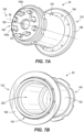
FIGS. 7A and 7B depict first and second perspective views of a lower retaining extension of the shaft assembly shown inFIG. 3 . -
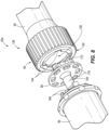
FIG. 8 depicts an exploded perspective view of a lower portion of the shaft assembly shown inFIG. 3 - Before any embodiments are explained in detail, it is to be understood that the embodiments described herein are provided as examples and the details of construction and the arrangement of the components described herein or illustrated in the accompanying drawings should not be considered limiting. Also, it is to be understood that the phraseology and terminology used herein is for the purpose of description and should not be regarded as limited. The use of "including," "comprising" or "having" and variations thereof herein is meant to encompass the items listed thereafter and equivalents thereof as well as additional items. The terms "mounted," "connected" and "coupled" are used broadly and encompass both direct and indirect mounting, connecting and coupling. Further, "connected" and "coupled" are not restricted to physical or mechanical connections or couplings, and may include electrical connections or couplings, whether direct or indirect. Also, electronic communications and notifications may be performed using any known means including direct connections, wireless connections, and the like.
- Split-torque gearboxes require a large number of gears, bearings, and shafts to run multi-path power transmission from input shafts to output shafts. Many gearboxes require a rod housed within the shaft to retain components that transfer of rotational energy from one gear to another. However, the rods often have a large length over diameter ratio. This large length over diameter ratio may cause the rod to vibrate as vibration frequencies cross a critical mode. This vibration causes high stress in the rod.
- Exemplary embodiments address these issues by providing the required functionality of a shaft gear assembly while also eliminating the large length over diameter ratio rod that is often used to retain parts together. The shaft gear assembly includes integrated locking features built upon a stiff shaft with a smaller length over diameter ratio.
- With the elimination of the resonance sensitive rod, the number of parts and the weight of the design is reduced. The reduced number of parts also allows for reduced production cost and reduced development time. Additionally, by eliminating the large length over diameter ratio of the rod, the entire split-torque gearbox system has a higher reliability. As such, the exemplary embodiments described herein provide a lightweight solution, that reduces production costs while also increasing reliability of the system.
- Shown in
FIG. 1 is a schematic view of an embodiment of a rotary-wing aircraft 10. The coaxial rotary-wing aircraft 10 includes anairframe 12 with an extendingtail 14. A dual, counter-rotating coaxialmain rotor assembly 18 is located at theairframe 12 and rotates about a main rotor axis orfirst axis 20. Themain rotor assembly 18 is driven by a power source, for example, anengine 24 via a gearbox 36 (FIG. 2 ). Themain rotor assembly 18 includes anupper rotor assembly 28 driven in afirst direction 30 about themain rotor axis 20, and alower rotor assembly 32 driven in asecond direction 34 about themain rotor axis 20, opposite, but at the same or substantially same rotational speed, to thefirst direction 30. - While the
first direction 30 is illustrated as counterclockwise and thesecond direction 34 is illustrated as counterclockwise, it is to be appreciated that in some embodiments, the directions of rotation of theupper rotor assembly 28 andlower rotor assembly 32 may be reversed. Each of theupper rotor assembly 28 and thelower rotor assembly 32 include a plurality ofrotor blades 35 secured to arespective rotor hub 38. In some embodiments, the rotary-wing aircraft 10 further includes atranslational thrust system 41 located at the extendingtail 14 to provide translational thrust for the rotary-wing aircraft 10. Thetranslational thrust system 41 includes apropeller rotor 42 connected to and driven by theengine 24 via thegearbox 36 or additional transmission systems. In some embodiments, a second gearbox may be separately mounted from the gearbox 36 (e.g., in the tail 14) to provide power to thetranslational thrust system 41. While shown in the context of a pusher-prop configuration, it is understood that thepropeller rotor 42 could also be a puller prop or could be variably facing so as to provide torque in addition to or instead of translational thrust. It should be appreciated that althoughFIG. 1 depicts a coaxial rotary-wing aircraft 10 with apropeller rotor 42, the herein describedgearbox 36 arranged is operable to function in connection with a rotary-wing aircraft that does not include apropeller rotor 42 or in a non-coaxial aircraft having a single rotor assembly and tail rotor. - Shown in
FIG. 2 is a perspective view of thegearbox 36 according to one embodiment and in mechanical communication with an input mechanism (i.e., a motor output shaft). In the illustrated embodiment, thegearbox 36 includes more than one shaft assembly. Afirst shaft assembly 40a engages with the anupper bull gear 39, which is coupled with and drives thelower rotor assembly 32 ofFIG. 1 . Asecond shaft assembly 40b engages with the alower bull gear 43 which is coupled with and drivers theupper rotor assembly 28 ofFIG. 1 .FIG. 2 illustrates two shaft assemblies; however, in further embodiments of the invention thegearbox 36 may include fewer or more shaft assemblies. Although only thefirst shaft assembly 40a is described in detail below, it should be appreciated that thesecond shaft assembly 40b includes the same structure with differences described herein. - The
shaft assembly 40a includes anelongated shaft 60, a first, upper retainingextension 76, a second, lower retainingextension 84, and alock mechanism 80. In the illustrated embodiment, theshaft 60 is a quill shaft. Theshaft 60 is generally hollow and extends along thecentral axis 56 between afirst end 64 and asecond end 68. Acentral aperture 72 extends from thefirst end 64 to thesecond end 68. Theshaft 60 is generally cylindrical in shape, however, in further embodiments, theshaft 60 may be any of a plurality of different shapes. Thecentral aperture 72 allows for connecting the upper retainingextension 76 to thefirst end 64 of theshaft 60. - The
first end 64 of theshaft 60 is coupled to the upper retainingextension 76 by a fastening mechanism 77 (FIG. 4 ), such as a nut. Anend portion 73 of the upper retainingextension 76 extends into thecentral aperture 72 of theshaft 60, and thefastening mechanism 77 is threaded to theend portion 73 to couple the upper retainingextension 76 to theshaft 60. In further embodiments, different types of fastening mechanisms may be used to couple the upper retainingextension 76 to theshaft 60. Thesecond end 68 of theshaft 60 is coupled to thelock mechanism 80, and thelock mechanism 80 removably couples theshaft 60 to thelower retaining extension 84. In the illustrated embodiments, the upper retainingextension 76 and thelower retaining extension 84 are coaxial with theshaft 60 and both generally cylindrical in shape; however, in further embodiments, the upper retainingextension 76 and thelower retaining extension 84 may be any of a plurality of different shapes. - The
shaft assembly 40a is coupled with ageartrain 44 of thegearbox 36 that includes afirst gear 48, which is a pinion in the illustrated embodiment, and asecond gear 52, which is a driving gear in the illustrated embodiment. In further embodiments, thefirst gear 48 may be a double helical pinion and thesecond gear 52 may be a spur gear. Alternatively, thefirst gear 48 and thesecond gear 52 may be any of a plurality of different types of gears (i.e., pinion, bevel, etc.). Theshaft assembly 40a, as well as thefirst gear 48 and thesecond gear 52, rotate about acentral axis 56. During operation, power from theengine 24 rotates a first stage of gears (not shown) which causes rotation of thesecond gear 52. Rotation of thesecond gear 52 rotates theshaft assembly 40a and thereby rotation of thefirst gear 48 therewith. Rotation of thefirst gear 48 rotates theupper bull gear 39, which causes rotation of the lower rotor assembly 32Thesecond shaft assembly 40b is similarly coupled with athird gear 49 and afourth gear 50. Theshaft assembly 40b as well as thethird gear 49 and thefourth gear 50 rotate about a secondcentral axis 57. During operation of thesecond shaft assembly 40b, rotation of thefourth gear 50 rotates theshaft assembly 40b and thereby rotation of thethird gear 49 therewith. Rotation of thethird gear 49 rotates thelower bull gear 43, which causes rotation of theupper rotor assembly 28. - In the illustrated embodiment, the
first gear 48 surrounds and is coupled with theshaft 60 and the upper retainingextension 76, and thesecond gear 52 surrounds and is coupled with theshaft 60 and thelower retaining extension 84. Thefirst gear 48 is coupled to thefirst end 64 of theshaft 60 and the upper retainingextension 76 for rotation with theshaft assembly 40a. Likewise, thesecond gear 52 is coupled to thesecond end 68 of theshaft 60 and thelower retaining mechanism 84 for rotation with theshaft assembly 40a. In the illustrated embodiment, each of thefirst gear 48 and thesecond gear 52 are coupled to therespective end shaft 60 and retainingextension first gear 48 may be coupled with only theshaft 60 or only theupper retaining mechanism 76. Likewise, thesecond gear 52 may be coupled with only theshaft 60 or only thelower retaining extension 84. Theshaft assembly 40a transfers rotational energy from thesecond gear 52 to thefirst gear 48 and in some implementations is under a torsional force. As shown, the gears are concentrically located to rotate about thecentral axis 56 with theshaft assembly 40a, however the invention is not limited thereto. -
FIGS. 3 and4 illustrate theshaft assembly 40a including theshaft 60, the upper retainingextension 76, thelock mechanism 80, and thelower retaining extension 84. Thecentral axis 56 of theshaft assembly 40a extends through theshaft 60, the upper retainingextension 76, thelock mechanism 80, and thelower retaining extension 84, which are coaxially arranged along thecentral axis 56. - The
first end 64 of theshaft 60 includes afirst spline portion 88 and thesecond end 68 of theshaft 60 includes asecond spline portion 92. Thefirst spline portion 88 and thesecond spline portion 92 are each defined by a plurality ofsplines 96 extending circumferentially around an outer surface of theshaft 60. Thefirst spline portion 88 is splined with thefirst gear 48, and thesecond spline portion 92 is splined with thesecond gear 52. - The
shaft 60 has ashaft length 100 spanning from thefirst end 64 to thesecond end 68. Theshaft 60 also has ashaft diameter 104. Theshaft diameter 104 is the diameter of theshaft 60 at amidpoint 108 of theshaft 60, which is halfway between thefirst end 64 and thesecond end 68. In the illustrated embodiment, a diameter at thefirst end 64 of theshaft 60 and a diameter at thesecond end 68 of theshaft 60 are similar. The shaft diameter 104 (i.e., the diameter at themidpoint 108 of the shaft 60) is less than the diameters of thefirst end 64 of theshaft 60 and thesecond end 68 of theshaft 60. Theshaft 60 has a length over diameter ratio that is calculated by dividing theshaft length 100 by theshaft diameter 104. Theshaft length 100 and theshaft diameter 104 may vary greatly, however, theshaft 60 is configured such that torsional wind up of thequill shaft 60 is sufficient for desired load sharing between redundant gears of thesplit torque gearbox 36. The redundant gears may be any of a plurality of gears within thegeartrain 44. Additionally or alternately, the redundant gears may be operably connected with thefirst gear 48 or thesecond gear 52. In the present embodiment, theshaft diameter 104 is between 1 and 3 inches. In the present embodiment, theshaft length 100 is between 6 and 15 inches, and the shaft length over diameter ratio ranges between 15:1 to 2:1. In other embodiments, theshaft diameter 104 may have other nominal diameters. - The
upper retaining extension 76 includes theend portion 73 receivable by thecentral aperture 72 on thefirst end 64 of theshaft 60. Theend portion 73 may be generally cylindrical in shape. Anoil dam sleeve 116 is coupled with thefirst end 64 of theshaft 60 and the upper retainingextension 76. Theoil dam 116 provides oil to thesplines 96 to lubricate thesplines 96 and resist fretting of thesplines 96. Theupper retaining extension 76 has anupper extension length 120. Theupper extension length 120 extends from thefirst end 64 of theshaft 60 to a top end of the upper retainingextension 76. In further embodiments, retaining extensions of adifferent length 120 may be used based upon the relative position between theshaft 60 and the respective rotor assembly (i.e., the distance needed to couple theshaft 60 to the associated rotor assembly). For example, in thefirst shaft assembly 40a, which engages with theupper bull gear 39, thelength 120 of the upper retainingextension 76 is greater than a length of the upper retaining extension in thesecond shaft assembly 40b, which engages with thelower bull gear 43. Referring toFIG. 2 , the upper retaining extension shown of thesecond shaft assembly 40b is a disc. - The
lower retaining extension 84 includes anexterior portion 124 that receives a retainingring 136 for providing a connection between thelower retaining extension 84 and thefirst gear 48. Thelower retaining extension 84 has alower extension length 132. Thelower extension length 132 extends from thesecond end 68 of theshaft 60 to a bottom end of thelower retaining extension 84. In further embodiments, lower retaining extensions of adifferent length 132 may be used based upon the relative position between theshaft 60 and therespective rotor assembly 28, 32 (i.e., the distance needed to couple theshaft 60 to the associated rotor assembly). For example, in thefirst shaft assembly 40a, which engages with thelower rotor assembly 32, thelength 132 of thelower retaining extension 84 is greater than a length of thelower retaining extension 84 in thesecond shaft assembly 40b, which engages with theupper rotor assembly 28. - Providing the retaining
extensions first gear 48 and thesecond gear 52 can float along theaxis 56 to accommodate gearbox component misalignment due to deflection under varying loads. In some embodiments, theshaft assembly 40a, and thereby the retainingextensions - As shown in
FIG. 4 , theshaft assembly 40a includes a plurality of retainingrings 136 to facilitate retention of the upper andlower retaining extensions shaft 60. Retaining rings 136 are received by the upper retainingextension 76 as well as thelower retaining extension 84. The retaining rings 136 retain the upper retainingextension 76 and thelower retaining extension 84 to theshaft 60 by filling any gaps between the retainingextension 76 and theshaft 60. In further embodiments, retainingrings 136 may not be included in theshaft assembly 40a. Alternately, a different number of retaining rings 136 may be included in the shaft assembly 40. -
FIGS. 5-8 illustrate alower portion 138 of theshaft assembly 40a including the attachment of thesecond end 68 of theshaft 60 to thelower retaining extension 84 by thelock mechanism 80. Thesecond end 68 of theshaft 60 includes anend face 140 defining anopening 139 to thecentral aperture 72 for receiving thelock mechanism 80. Theopening 139 includes a plurality ofrecesses 144 formed on theend face 140 that define an interface for receiving thelock mechanism 80. Referring toFIG. 5 , therecesses 144 formed on theend face 140 of thesecond end 68 of theshaft 60 are positioned circumferentially around thecentral axis 56, which corresponds with the center of theend face 140. In the illustrated embodiment, theopening 139 includes fourrecesses 144 that extend radially from thecentral aperture 72 of theshaft 60. Eachrecess 144 is generally rectangular in shape with rounded off edges. Thecentral aperture 72 of theshaft 60 extends through theend face 140. Theopening 139 of theend face 140 is therefore defined by a circle with four equally spacedrecesses 144 extending around the circle. In further embodiments, theopening 139 may have other shapes and may include fewer or more recesses 144. - As shown in
FIG. 6A and 6B , thelock mechanism 80 is generally circular in shape, however, in further embodiments, thelock mechanism 80 may be another shape, including those complementary to the shape of theopening 139. In the present embodiment, the lock mechanism is a retaining plug configured to retain thelower retaining extension 84 to theshaft 60. Thelock mechanism 80 can be coupled with thelower retaining extension 84 and with theshaft 60 to couple the two together. Thelock mechanism 80 includes abase plate 156 having afirst side 148 and asecond side 152. Thefirst side 148 of thelock mechanism 80 is removably coupled with theshaft 60 and thesecond side 152 is removably coupled with thelower retaining extension 84. - The
first side 148 of thebase plate 156 includes a first projectingportion 160 extending axially therefrom for coupling with theshaft 60, and thesecond side 152 includes a second projectingportion 164 extending axially therefrom for coupling with thelower retaining extension 84. In the illustrated embodiment, the first projectingportion 160 is defined by acenter portion 168 with four equally spaced-apart arms 172 extending circumferentially around thecenter portion 168. Thearms 172 are sized and shaped to be received within therecesses 144 on theshaft 60. In other words, the first projectingportion 160 on thelock mechanism 80 is an inverse shape to that of theopening 139 formed on theend face 140 of theshaft 60. The spaced-apartarms 172 are generally rectangular in shape with rounded off edges. In further embodiments, there may be fewer ormore arms 172, or the shape of the protrusion may be different. In still further embodiments, the projectingportion 160 may have other shapes that complement and fit within theopening 139 of theshaft 60. - The
base plate 156 of thelock mechanism 80 includes a plurality ofholes 176 extending radially around thecentral axis 56 and along an outer edge of thebase plate 156. In the illustrated embodiment, thebase plate 156 includes eightholes 176, each generally rectangular in shape with rounded edges. However, in further embodiments, thebase plate 156 may include fewer ormore holes 176 and/or the shape of theholes 176 may have a different shape. - The second projecting
portion 164 of thelock mechanism 80 extends axially from thesecond side 148 of thebase plate 156 and along thecentral axis 56. The second projectingportion 164 is generally cylindrical; however, in further embodiments, the second projectingportion 164 may be other shapes. - As shown in
FIGS. 7A and 7B , thelower retaining extension 84 is generally cylindrical in shape and includes ahollow interior 200. Thelower retaining extension 84 includes abody 192 defining the interior 200 and having afirst end 149 defining anend face 141 and asecond end 153 opposite thefirst end 149. Theend face 141 includes anaperture 180 for receiving the second projectingportion 164 of thelock mechanism 80. Thelower retaining extension 84 further includes a plurality of retainingprotrusions 184 extending axially from theend face 141. The retainingprotrusions 184 are arranged radially outward from and circumferentially around thecentral axis 56 of thelower retaining extension 84. The retainingprotrusions 184 are receivable through theholes 176 located on thelock mechanism 80 for securing thelock mechanism 80 to thelower retaining extension 84. The retainingprotrusions 184 include retainingprotrusions 184a having a first axial length along thecentral axis 56 and retainingprotrusions 184b having a second axial length along thecentral axis 56 shorter than the first length. In the present embodiment, thelower retaining extension 84 includes fourlong retaining protrusions 184a and fourshort retaining protrusions 184b. The retainingprotrusions 184 are each generally rectangular in shape with rounded edges. The retainingprotrusions 184 are an inverse shape and complementary to the shape of theholes 176 formed on thebase plate 156 of thelock mechanism 80. - The
second end 153 of thelower retaining extension 84 includes ashoulder 188 extending radially outward from thebody 192. Achamfer 196 extends between thebody 192 and theshoulder 188. Thelower retaining extension 84 is open at thesecond end 153 such that ahollow interior 200 is accessible. Thesecond end 152 of thelower retaining extension 84 further includes theexterior portion 124 defined by theshoulder 188 and thebody 192. Theexterior portion 124 receives the lock ring 128 to secure theshaft assembly 40a together. - During assembly, the
lock mechanism 80 is inserted into thesecond end 68 of theshaft 60 such that thearms 172 are seated within therecesses 144 of theopening 139 on theend face 140 of theshaft 60. When therecesses 144 are aligned with thearms 172, thelock mechanism 80 is in an unlocked position, which permits removal of thelock mechanism 80 from thesecond end 68 of theshaft 60. Thelock mechanism 80 is then rotated within thesecond end 68 such that therecesses 144 no longer align with thearms 172. In this instance, thelock mechanism 80 is in a locked position, which prohibits removal of thelock mechanism 80 from thesecond end 68 of theshaft 60. Once thelock mechanism 80 is inserted and in the locked position, the retainingprotrusions 184 of thelower retaining extension 84 are inserted into theholes 176 of thelock mechanism 80. Thelower retaining extension 84 is further coupled to thelock mechanism 80 by afastening mechanism 177, such as a nut. Thefastening mechanism 177 is threaded to the second projectingportion 164 of thelock mechanism 80 to connect thelower retaining extension 80 to thelock mechanism 80. - Various features and advantages of the embodiment described herein are set forth in the following claims.
Claims (15)
- A shaft assembly for a gearbox, the shaft assembly comprising:a shaft having a first end and a second end, the second end including at least one recess formed on an end face;a lock mechanism removably coupled to the second end of the shaft, the lock mechanism including a first side and a second side, the first side including a first projecting portion configured to engage with the at least one recess on the shaft, and the second side including a second projecting portion; anda retaining extension including an aperture configured to receive the second projecting portion of the lock mechanism through the aperture.
- The shaft assembly of claim 1, wherein the first projecting portion includes a central portion with arms radially extending therefrom, the arms configured for receipt by the at least one recess for coupling the shaft to the retaining extension.
- The shaft assembly of claim 2, wherein when the recesses are aligned with the arms, the lock mechanism is in an unlocked position, and when the lock mechanism is rotated within the second end such that the recesses no longer align with the arms, the lock mechanism is in a locked position.
- The shaft assembly of claim 3, wherein the unlocked position permits removal of the lock mechanism, and the locked position prohibits removal of the lock mechanism from the second end of the shaft.
- The shaft assembly of one of claims 1-4, wherein the retaining extension is a lower retaining extension and further comprising an upper retaining extension configured to be coupled with the first end of the shaft.
- A split torque gearbox comprising:a first gear oriented to rotate about an axis;a second gear spaced from the first gear and oriented to rotate about the axis; anda shaft assembly according to one of claims 1-5 extending between the first gear and the second gear, the shaft assembly including the shaft having the first end coupled with the first gear and the second end coupled with the second gear.
- The split torque gearbox of claim 6, wherein the shaft has a shaft length over shaft diameter ratio that ranges between 15:1 to 2:1.
- The split torque gearbox of claim 6 or 7, wherein the retaining extension is a lower retaining extension and further comprising an upper retaining extension configured to be coupled with the first end.
- The split torque gearbox of one of claims 6-8, wherein the first end of the shaft is surrounded by and coupled with the first gear and the first gear is a double helical pinion, and the second end of the shaft is surrounded by and coupled with the second gear and the second gear is a spur gear.
- A rotary-wing aircraft comprising:a first rotor rotatable about a first axis in a first direction to provide lift; anda gearbox according to one of claims 6-9.
- The rotary-wing aircraft of claim 10, wherein the first end of the shaft is surrounded by and coupled with the first gear and the first gear is a double helical pinion.
- The rotary-wing aircraft of claim 10 or 11, wherein the second end of the shaft is surrounded by and coupled with the second gear and the second gear is a spur gear.
- The rotary-wing aircraft of one of claims 10-12 wherein the first projecting portion includes a central portion with arms radially extending therefrom, the arms configured for receipt by the at least one recess for coupling the shaft to the retaining extension.
- The rotary-wing aircraft of one of claims 10-13, wherein the retaining extension is coupled to the lock mechanism by a fastening mechanism.
- The rotary-wing aircraft of claim 14, wherein the fastening mechanism is a nut that is threaded to the second projecting portion of the lock mechanism.
Applications Claiming Priority (1)
| Application Number | Priority Date | Filing Date | Title |
|---|---|---|---|
| US18/400,698 US12448120B2 (en) | 2023-12-29 | 2023-12-29 | Shaft assembly for split torque gear box |
Publications (1)
| Publication Number | Publication Date |
|---|---|
| EP4578788A1 true EP4578788A1 (en) | 2025-07-02 |
Family
ID=93840633
Family Applications (1)
| Application Number | Title | Priority Date | Filing Date |
|---|---|---|---|
| EP24217873.9A Pending EP4578788A1 (en) | 2023-12-29 | 2024-12-05 | Shaft assembly for split torque gear box |
Country Status (2)
| Country | Link |
|---|---|
| US (1) | US12448120B2 (en) |
| EP (1) | EP4578788A1 (en) |
Citations (6)
| Publication number | Priority date | Publication date | Assignee | Title |
|---|---|---|---|---|
| WO2012024677A2 (en) * | 2010-08-20 | 2012-02-23 | Redviking Group, Llc | Transmission test system |
| US20150114772A1 (en) * | 2013-10-30 | 2015-04-30 | Sikorsky Aircraft Corporation | Rotor brake |
| US20160152342A1 (en) * | 2013-09-04 | 2016-06-02 | Sikorsky Aircraft Corporation | Torque split gearbox for rotary wing aircraft |
| CN108696048A (en) * | 2018-07-11 | 2018-10-23 | 浙江联宜电机有限公司 | Wheel hub and motor output shaft releasing mechanism |
| WO2023144157A1 (en) * | 2022-01-28 | 2023-08-03 | Brp-Rotax Gmbh & Co. Kg | Aircraft propeller drive system |
| US11787551B1 (en) * | 2022-10-06 | 2023-10-17 | Archer Aviation, Inc. | Vertical takeoff and landing aircraft electric engine configuration |
Family Cites Families (10)
| Publication number | Priority date | Publication date | Assignee | Title |
|---|---|---|---|---|
| US2610786A (en) | 1946-06-25 | 1952-09-16 | Gen Electric | Axial flow compressor |
| FR2317501A1 (en) * | 1975-07-09 | 1977-02-04 | Snecma | COUPLING DEVICE FOR GAS TURBINE ENGINE |
| US5462410A (en) | 1994-11-10 | 1995-10-31 | United Technologies Corporation | Damper and seal for propeller quill shaft |
| FR2756542B1 (en) * | 1996-11-29 | 1999-02-12 | Eurocopter France | INSTALLATION FOR MOUNTING A MOTOR ON A FLOOR AND CONNECTING ITS OUTPUT SHAFT WITH AT LEAST ONE DRIVEN MECHANISM |
| US7144349B2 (en) * | 2004-04-06 | 2006-12-05 | Pratt & Whitney Canada Corp. | Gas turbine gearbox |
| US10746253B2 (en) | 2015-08-20 | 2020-08-18 | Sikorsky Aircraft Corporation | Vibration damping device for an elongated member |
| FR3047471B1 (en) * | 2016-02-08 | 2018-02-16 | Safran Transmission Systems | CHAIN MOTOR |
| US10648519B2 (en) * | 2018-03-07 | 2020-05-12 | Textron Innovations Inc. | Torque path coupling assemblies for tiltrotor aircraft |
| US11480212B2 (en) * | 2019-09-11 | 2022-10-25 | Pratt & Whitney Canada Corp. | Nut locking feature |
| US12187419B2 (en) * | 2022-08-25 | 2025-01-07 | Lockheed Martin Corporation | Rotary shaft for an aircraft |
-
2023
- 2023-12-29 US US18/400,698 patent/US12448120B2/en active Active
-
2024
- 2024-12-05 EP EP24217873.9A patent/EP4578788A1/en active Pending
Patent Citations (6)
| Publication number | Priority date | Publication date | Assignee | Title |
|---|---|---|---|---|
| WO2012024677A2 (en) * | 2010-08-20 | 2012-02-23 | Redviking Group, Llc | Transmission test system |
| US20160152342A1 (en) * | 2013-09-04 | 2016-06-02 | Sikorsky Aircraft Corporation | Torque split gearbox for rotary wing aircraft |
| US20150114772A1 (en) * | 2013-10-30 | 2015-04-30 | Sikorsky Aircraft Corporation | Rotor brake |
| CN108696048A (en) * | 2018-07-11 | 2018-10-23 | 浙江联宜电机有限公司 | Wheel hub and motor output shaft releasing mechanism |
| WO2023144157A1 (en) * | 2022-01-28 | 2023-08-03 | Brp-Rotax Gmbh & Co. Kg | Aircraft propeller drive system |
| US11787551B1 (en) * | 2022-10-06 | 2023-10-17 | Archer Aviation, Inc. | Vertical takeoff and landing aircraft electric engine configuration |
Also Published As
| Publication number | Publication date |
|---|---|
| US12448120B2 (en) | 2025-10-21 |
| US20250214699A1 (en) | 2025-07-03 |
Similar Documents
| Publication | Publication Date | Title |
|---|---|---|
| EP3066007B1 (en) | Counter-rotating rotor system with stationary standpipe | |
| RU2716718C2 (en) | Airborne vehicle and planetary gear systems | |
| US5807202A (en) | Differential speed transmission | |
| WO1989002041A1 (en) | Compound planetary gear assembly | |
| US11982320B2 (en) | Transmission | |
| EP3041737A1 (en) | Torque split gearbox for rotary wing aircraft | |
| WO1998016762A1 (en) | Concentric face gear transmission assembly | |
| US10875634B2 (en) | Drive train | |
| US4118997A (en) | Bevel gearing | |
| CN101535128B (en) | Multiple drive-path transmission with torque-splitting differential mechanism | |
| EP3921231A1 (en) | Drive, in particular for the main rotor of a rotary craft | |
| EP2873613B1 (en) | Counter-rotating rotor system with static mast | |
| US12448120B2 (en) | Shaft assembly for split torque gear box | |
| US10724625B2 (en) | Torsionally compliant geartrain carrier assembly | |
| US8550950B2 (en) | Planetary reduction gearbox | |
| EP3137377B1 (en) | Radially compliant quill shaft | |
| EP1295788A2 (en) | Hybrid power input quill for transmissions | |
| EP4328133B1 (en) | Rotary shaft for an aircraft | |
| US12054276B2 (en) | Installation of gear assemblies in aircraft gearboxes | |
| US10941836B2 (en) | Rotorcraft internal transfer member transmission | |
| EP4459156B1 (en) | Gearbox assembly for an aircraft propulsion system | |
| US10393218B2 (en) | Viscous damper | |
| US20100197415A1 (en) | Coupling with slack-takeup, a rotor, and a rotary wing aircraft | |
| EP4715188A2 (en) | Clutch assembly for an aircraft propulsion system gear train | |
| EP4497677A1 (en) | Rotary actuator assembly |
Legal Events
| Date | Code | Title | Description |
|---|---|---|---|
| PUAI | Public reference made under article 153(3) epc to a published international application that has entered the european phase |
Free format text: ORIGINAL CODE: 0009012 |
|
| STAA | Information on the status of an ep patent application or granted ep patent |
Free format text: STATUS: THE APPLICATION HAS BEEN PUBLISHED |
|
| AK | Designated contracting states |
Kind code of ref document: A1 Designated state(s): AL AT BE BG CH CY CZ DE DK EE ES FI FR GB GR HR HU IE IS IT LI LT LU LV MC ME MK MT NL NO PL PT RO RS SE SI SK SM TR |
|
| STAA | Information on the status of an ep patent application or granted ep patent |
Free format text: STATUS: REQUEST FOR EXAMINATION WAS MADE |
|
| 17P | Request for examination filed |
Effective date: 20251219 |
|
| STAA | Information on the status of an ep patent application or granted ep patent |
Free format text: STATUS: EXAMINATION IS IN PROGRESS |