EP4578786A1 - Centralized multi engine startup system for palletized applications - Google Patents
Centralized multi engine startup system for palletized applications Download PDFInfo
- Publication number
- EP4578786A1 EP4578786A1 EP24221872.5A EP24221872A EP4578786A1 EP 4578786 A1 EP4578786 A1 EP 4578786A1 EP 24221872 A EP24221872 A EP 24221872A EP 4578786 A1 EP4578786 A1 EP 4578786A1
- Authority
- EP
- European Patent Office
- Prior art keywords
- gas
- umbilical
- vehicle
- energized
- startup system
- Prior art date
- Legal status (The legal status is an assumption and is not a legal conclusion. Google has not performed a legal analysis and makes no representation as to the accuracy of the status listed.)
- Pending
Links
Images

Classifications
-
- B—PERFORMING OPERATIONS; TRANSPORTING
- B64—AIRCRAFT; AVIATION; COSMONAUTICS
- B64D—EQUIPMENT FOR FITTING IN OR TO AIRCRAFT; FLIGHT SUITS; PARACHUTES; ARRANGEMENT OR MOUNTING OF POWER PLANTS OR PROPULSION TRANSMISSIONS IN AIRCRAFT
- B64D1/00—Dropping, ejecting, releasing or receiving articles, liquids, or the like, in flight
- B64D1/02—Dropping, ejecting, or releasing articles
- B64D1/04—Dropping, ejecting, or releasing articles the articles being explosive, e.g. bombs
-
- F—MECHANICAL ENGINEERING; LIGHTING; HEATING; WEAPONS; BLASTING
- F02—COMBUSTION ENGINES; HOT-GAS OR COMBUSTION-PRODUCT ENGINE PLANTS
- F02C—GAS-TURBINE PLANTS; AIR INTAKES FOR JET-PROPULSION PLANTS; CONTROLLING FUEL SUPPLY IN AIR-BREATHING JET-PROPULSION PLANTS
- F02C7/00—Features, components parts, details or accessories, not provided for in, or of interest apart form groups F02C1/00 - F02C6/00; Air intakes for jet-propulsion plants
- F02C7/32—Arrangement, mounting, or driving, of auxiliaries
-
- B—PERFORMING OPERATIONS; TRANSPORTING
- B64—AIRCRAFT; AVIATION; COSMONAUTICS
- B64D—EQUIPMENT FOR FITTING IN OR TO AIRCRAFT; FLIGHT SUITS; PARACHUTES; ARRANGEMENT OR MOUNTING OF POWER PLANTS OR PROPULSION TRANSMISSIONS IN AIRCRAFT
- B64D1/00—Dropping, ejecting, releasing or receiving articles, liquids, or the like, in flight
- B64D1/02—Dropping, ejecting, or releasing articles
- B64D1/08—Dropping, ejecting, or releasing articles the articles being load-carrying devices
- B64D1/12—Releasing
-
- F—MECHANICAL ENGINEERING; LIGHTING; HEATING; WEAPONS; BLASTING
- F41—WEAPONS
- F41F—APPARATUS FOR LAUNCHING PROJECTILES OR MISSILES FROM BARRELS, e.g. CANNONS; LAUNCHERS FOR ROCKETS OR TORPEDOES; HARPOON GUNS
- F41F3/00—Rocket or torpedo launchers
- F41F3/04—Rocket or torpedo launchers for rockets
- F41F3/06—Rocket or torpedo launchers for rockets from aircraft
-
- F—MECHANICAL ENGINEERING; LIGHTING; HEATING; WEAPONS; BLASTING
- F05—INDEXING SCHEMES RELATING TO ENGINES OR PUMPS IN VARIOUS SUBCLASSES OF CLASSES F01-F04
- F05D—INDEXING SCHEME FOR ASPECTS RELATING TO NON-POSITIVE-DISPLACEMENT MACHINES OR ENGINES, GAS-TURBINES OR JET-PROPULSION PLANTS
- F05D2220/00—Application
- F05D2220/30—Application in turbines
- F05D2220/32—Application in turbines in gas turbines
- F05D2220/323—Application in turbines in gas turbines for aircraft propulsion, e.g. jet engines
Definitions
- the present disclosure is directed to the improved launch capability for vehicles with turbojet engines arranged on pallets for launch from an aircraft. Particularly, a centralized approach to starting the vehicle turbojet engines is employed.
- centralized multi engine startup system comprising a pallet structure; an energized gas source supported by the pallet structure; an umbilical gas line fluidly coupled to the energized gas source; and a vehicle in operative communication with the umbilical gas line, wherein each of the energized gas source and umbilical gas line are coupled to the pallet structure and remain with the pallet structure responsive to a vehicle launch from the pallet structure.
- Particular embodiments further may include at least one, or a plurality of, the following optional features, alone or in combination with each other:
- a further embodiment of any of the foregoing embodiments may additionally and/or alternatively include the energized gas source comprises at least one of a gas generator and a start cartridge.
- a further embodiment of any of the foregoing embodiments may additionally and/or alternatively include the gas generator and a start cartridge are configured to produce an energized gas configured to start a gas turbine engine associated with the vehicle.
- a further embodiment of any of the foregoing embodiments may additionally and/or alternatively include the umbilical gas line is fluidly coupled to a propulsion module in operative communication with the vehicle.
- a further embodiment of any of the foregoing embodiments may additionally and/or alternatively include the centralized multi engine startup system further comprising multiple vehicles supported within the pallet structure, wherein the multiple vehicles are each fluidly coupled to the umbilical gas line.
- a further embodiment of any of the foregoing embodiments may additionally and/or alternatively include the centralized multi engine startup system according further comprising a quick release interface in fluid communication with the umbilical gas line, the quick release in operative communication with a propulsion module associated with the vehicle.
- a further embodiment of any of the foregoing embodiments may additionally and/or alternatively include the pallet structure being configured to support multiple vehicles for deployment from an aircraft.
- a centralized multi engine startup system comprising a pallet structure; an energized gas source supported by the pallet structure; an umbilical gas line fluidly coupled to the energized gas source; and at least one vehicle in operative communication with the umbilical gas line; a propulsion module fluidly coupled to the umbilical gas line; the propulsion module in operative communication with the at least one vehicle, wherein each of the energized gas source and umbilical gas line are coupled to the pallet structure and remain with the pallet structure responsive to a vehicle launch from the pallet structure.
- Particular embodiments further may include at least one, or a plurality of, the following optional features, alone or in combination with each other:
- a further embodiment of any of the foregoing embodiments may additionally and/or alternatively include the propulsion module comprises a gas turbine engine.
- a further embodiment of any of the foregoing embodiments may additionally and/or alternatively include the energized gas source comprises at least one of a gas generator and a start cartridge.
- a further embodiment of any of the foregoing embodiments may additionally and/or alternatively include the gas generator and a start cartridge are configured to produce an energized gas configured to start a gas turbine engine associated with the vehicle.
- a further embodiment of any of the foregoing embodiments may additionally and/or alternatively include the centralized multi engine startup system further comprising multiple vehicles supported within the pallet structure, wherein the multiple vehicles are each fluidly coupled to the umbilical gas line.
- a process for employing a centralized multi engine startup system comprising a pallet structure; supporting an energized gas source with the pallet structure; fluidly coupling an umbilical gas line to the energized gas source; configuring at least one vehicle in operative communication with the umbilical gas line; fluidly coupling a propulsion module with the umbilical gas line; configuring the propulsion module in operative communication with the at least one vehicle; and fixing each of the energized gas source and umbilical gas line to the pallet structure responsive to a vehicle launch from the pallet structure.
- Particular embodiments further may include at least one, or a plurality of, the following optional features, alone or in combination with each other:
- a further embodiment of any of the foregoing embodiments may additionally and/or alternatively include the energized gas source comprises at least one of a gas generator and a start cartridge.
- a further embodiment of any of the foregoing embodiments may additionally and/or alternatively include the process further comprising producing an energized gas from at least one of the gas generator and the start cartridge; and configuring the energized gas to start a gas turbine engine associated with the vehicle.
- a further embodiment of any of the foregoing embodiments may additionally and/or alternatively include the propulsion module comprises a gas turbine engine.
- a further embodiment of any of the foregoing embodiments may additionally and/or alternatively include the process further comprising configuring a quick release interface in fluid communication with the umbilical gas line, the quick release in operative communication with the propulsion module associated with the at least one vehicle.
- a further embodiment of any of the foregoing embodiments may additionally and/or alternatively include the process further comprising supporting multiple vehicles within the pallet structure; fluidly coupling the multiple vehicles to the umbilical gas line.
- a further embodiment of any of the foregoing embodiments may additionally and/or alternatively include the pallet structure being configured to support multiple vehicles for deployment from an aircraft.
- the centralized multi engine startup system 10 can include an energized gas source 12 fluidly coupled to an umbilical gas line 14.
- the umbilical gas line 14 is fluidly coupled to at least one vehicle 16.
- multiple vehicles 16 are supported by a storage structure 18 (e.g., pallet structure 18, or the like).
- the pallet structure 18 is configured to rack and stack multiple vehicles 16 for deployment from an aircraft 20.
- the centralized multi engine startup system 10 is in operative communication with the pallet structure 18.
- the umbilical gas line 14 is manifolded and fluidly coupled to each vehicle 16 and configured to supply energized gas 22 from the energized gas source 12 connected to a propulsion module 24 of the vehicle 16, providing necessary gas supplies to start the engine 26 of each vehicle 16 during palletized delivery.
- the centralized multi engine startup system 10 is configured to provide energized gas 22 for ignition and gas expansion along with an oxygen supply required to enrich the combustor air of the engine 26.
- the energized gas 22 includes rapidly expanding gas and oxygen.
- the umbilical gas line 14 is fluidly coupled with a quick release interface 34.
- the quick release interface 34 is configured to remain coupled during energized gas 22 injection but then decouple upon vehicle safe separation mode.
- the quick release interface 34 is fluidly coupled to the engine turbine rotor as well as the combustor of the engine 26. At this point of the deployment, the engine 26 starts and is in an idle mode.
- the vehicle(s) 16 can be released from the pallet structure 18 under the safe separation mode.
- the Fig. 4 shows the various stages of deployment, safe separation, engine start, full start and wing deployment so that the vehicle can proceed with the predetermined mission.
- a technical advantage of the disclosed centralized multi engine startup system can include combining the starting elements of each of the engines for the vehicles onto a central pallet location.
Landscapes
- Engineering & Computer Science (AREA)
- Aviation & Aerospace Engineering (AREA)
- Chemical & Material Sciences (AREA)
- Combustion & Propulsion (AREA)
- General Engineering & Computer Science (AREA)
- Mechanical Engineering (AREA)
- Filling Or Discharging Of Gas Storage Vessels (AREA)
- Control Of Vehicle Engines Or Engines For Specific Uses (AREA)
Abstract
Description
- The present disclosure is directed to the improved launch capability for vehicles with turbojet engines arranged on pallets for launch from an aircraft. Particularly, a centralized approach to starting the vehicle turbojet engines is employed.
- Vehicles using small turbojets are being actively pursued for palletized launch. Effectively, a configuration of vehicles is arranged on a pallet which is deployed at altitude from an aircraft. Each vehicle possesses its own start-up capability which is initiated as the vehicle drops from the pallet. The architecture for engine start-up remains on the vehicle for the duration of the mission. Start-up hardware can be expensive and takes up volume in the vehicle. Typically start cartridges and O2 bottles are required to commence engine operation and both elements contain ancillary hardware to attach the module to the engine.
- In accordance with the present disclosure, there is provided centralized multi engine startup system comprising a pallet structure; an energized gas source supported by the pallet structure; an umbilical gas line fluidly coupled to the energized gas source; and a vehicle in operative communication with the umbilical gas line, wherein each of the energized gas source and umbilical gas line are coupled to the pallet structure and remain with the pallet structure responsive to a vehicle launch from the pallet structure.
- Particular embodiments further may include at least one, or a plurality of, the following optional features, alone or in combination with each other:
- A further embodiment of any of the foregoing embodiments may additionally and/or alternatively include the energized gas source comprises at least one of a gas generator and a start cartridge.
- A further embodiment of any of the foregoing embodiments may additionally and/or alternatively include the gas generator and a start cartridge are configured to produce an energized gas configured to start a gas turbine engine associated with the vehicle.
- A further embodiment of any of the foregoing embodiments may additionally and/or alternatively include the umbilical gas line is fluidly coupled to a propulsion module in operative communication with the vehicle.
- A further embodiment of any of the foregoing embodiments may additionally and/or alternatively include the centralized multi engine startup system further comprising multiple vehicles supported within the pallet structure, wherein the multiple vehicles are each fluidly coupled to the umbilical gas line.
- A further embodiment of any of the foregoing embodiments may additionally and/or alternatively include the centralized multi engine startup system according further comprising a quick release interface in fluid communication with the umbilical gas line, the quick release in operative communication with a propulsion module associated with the vehicle.
- A further embodiment of any of the foregoing embodiments may additionally and/or alternatively include the pallet structure being configured to support multiple vehicles for deployment from an aircraft.
- In accordance with the present disclosure, there is provided a centralized multi engine startup system comprising a pallet structure; an energized gas source supported by the pallet structure; an umbilical gas line fluidly coupled to the energized gas source; and at least one vehicle in operative communication with the umbilical gas line; a propulsion module fluidly coupled to the umbilical gas line; the propulsion module in operative communication with the at least one vehicle, wherein each of the energized gas source and umbilical gas line are coupled to the pallet structure and remain with the pallet structure responsive to a vehicle launch from the pallet structure.
- Particular embodiments further may include at least one, or a plurality of, the following optional features, alone or in combination with each other:
- A further embodiment of any of the foregoing embodiments may additionally and/or alternatively include the propulsion module comprises a gas turbine engine.
- A further embodiment of any of the foregoing embodiments may additionally and/or alternatively include the energized gas source comprises at least one of a gas generator and a start cartridge.
- A further embodiment of any of the foregoing embodiments may additionally and/or alternatively include the gas generator and a start cartridge are configured to produce an energized gas configured to start a gas turbine engine associated with the vehicle.
- A further embodiment of any of the foregoing embodiments may additionally and/or alternatively include the centralized multi engine startup system further comprising multiple vehicles supported within the pallet structure, wherein the multiple vehicles are each fluidly coupled to the umbilical gas line.
- A further embodiment of any of the foregoing embodiments may additionally and/or alternatively include the centralized multi engine startup system further comprising a quick release interface in fluid communication with the umbilical gas line, the quick release in operative communication with the propulsion module associated with the at least one vehicle.
- In accordance with the present disclosure, there is provided a process for employing a centralized multi engine startup system comprising a pallet structure; supporting an energized gas source with the pallet structure; fluidly coupling an umbilical gas line to the energized gas source; configuring at least one vehicle in operative communication with the umbilical gas line; fluidly coupling a propulsion module with the umbilical gas line; configuring the propulsion module in operative communication with the at least one vehicle; and fixing each of the energized gas source and umbilical gas line to the pallet structure responsive to a vehicle launch from the pallet structure.
- Particular embodiments further may include at least one, or a plurality of, the following optional features, alone or in combination with each other:
- A further embodiment of any of the foregoing embodiments may additionally and/or alternatively include the energized gas source comprises at least one of a gas generator and a start cartridge.
- A further embodiment of any of the foregoing embodiments may additionally and/or alternatively include the process further comprising producing an energized gas from at least one of the gas generator and the start cartridge; and configuring the energized gas to start a gas turbine engine associated with the vehicle.
- A further embodiment of any of the foregoing embodiments may additionally and/or alternatively include the propulsion module comprises a gas turbine engine.
- A further embodiment of any of the foregoing embodiments may additionally and/or alternatively include the process further comprising configuring a quick release interface in fluid communication with the umbilical gas line, the quick release in operative communication with the propulsion module associated with the at least one vehicle.
- A further embodiment of any of the foregoing embodiments may additionally and/or alternatively include the process further comprising supporting multiple vehicles within the pallet structure; fluidly coupling the multiple vehicles to the umbilical gas line.
- A further embodiment of any of the foregoing embodiments may additionally and/or alternatively include the pallet structure being configured to support multiple vehicles for deployment from an aircraft.
- Other details of the centralized multi engine startup system are set forth in the following detailed description and the accompanying drawings wherein like reference numerals depict like elements.
-
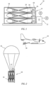
Fig. 1 is a schematic representation of an exemplary centralized multi engine startup system. -
Fig. 2 is a schematic representation of an exemplary centralized multi engine startup system being deployed. -
Fig. 3 is a schematic representation of an exemplary centralized multi engine startup system being deployed. -
Fig. 4 is a schematic representation of an exemplary centralized multi engine startup system being deployed. - Referring now to
Fig. 1 through Fig. 4 , there is illustrated an exemplary centralized multiengine startup system 10. The centralized multiengine startup system 10 can include anenergized gas source 12 fluidly coupled to anumbilical gas line 14. Theumbilical gas line 14 is fluidly coupled to at least onevehicle 16. In the embodiment shown,multiple vehicles 16 are supported by a storage structure 18 (e.g.,pallet structure 18, or the like). Thepallet structure 18 is configured to rack and stackmultiple vehicles 16 for deployment from anaircraft 20. The centralized multiengine startup system 10 is in operative communication with thepallet structure 18. - The
umbilical gas line 14 is manifolded and fluidly coupled to eachvehicle 16 and configured to supply energizedgas 22 from theenergized gas source 12 connected to apropulsion module 24 of thevehicle 16, providing necessary gas supplies to start theengine 26 of eachvehicle 16 during palletized delivery. The centralized multiengine startup system 10 is configured to provide energizedgas 22 for ignition and gas expansion along with an oxygen supply required to enrich the combustor air of theengine 26. - In an exemplary embodiment, the
energized gas source 12 can include agas generator 28 and/orstart cartridge 30 configured to generate the energizedgas 22. Thestart cartridge 30 can include a chemical mixture that reacts upon ignition to generate the energizedgas 22. In exemplary embodiments, thegas generator 28 and/orstart cartridge 30 can be a tank with compressed gas or any device configured to produce the energizedgas 22 to spin theengine 26. - Referring also to
Fig. 2 through Fig. 4 , in operation, the centralized multiengine startup system 10 is employed with thepallet structure 18 and remains with thepallet structure 18. As thepallet structure 18 containingmultiple vehicles 16 is deployed from theaircraft 20, thepallet structure 18 can be ejected from theaircraft 20. A drag-chute 32 deploys and orients thepallet structure 18 for proper alignment relative to gravitational forces and aerodynamic forces optimal for launching thevehicles 16. In another exemplary embodiment, as shown inFig. 2 , it is possible for thepallet structure 18 to remain onboard theaircraft 20. During deployment, pallet ejection and orientation, thepropulsion module 24 remains inactive. Upon proper initiation conditions, thegas generator 28 engages and supplies the energizedgas 22 through theumbilical gas line 14 to eachindividual vehicle 16. The energizedgas 22 includes rapidly expanding gas and oxygen. Theumbilical gas line 14 is fluidly coupled with aquick release interface 34. Thequick release interface 34 is configured to remain coupled during energizedgas 22 injection but then decouple upon vehicle safe separation mode. Thequick release interface 34 is fluidly coupled to the engine turbine rotor as well as the combustor of theengine 26. At this point of the deployment, theengine 26 starts and is in an idle mode. - After engine idle mode has been attained, the vehicle(s) 16 can be released from the
pallet structure 18 under the safe separation mode. TheFig. 4 , shows the various stages of deployment, safe separation, engine start, full start and wing deployment so that the vehicle can proceed with the predetermined mission. - The
energized gas source 12 along with thegas generator 28 and/orstart cartridge 30 andumbilical gas line 14 remain with thepallet structure 18. Thepallet structure 18 can be retained and reused for additional missions. - A technical advantage of the disclosed centralized multi engine startup system can include combining the starting elements of each of the engines for the vehicles onto a central pallet location.
- Another technical advantage of the disclosed centralized multi engine startup system can include weight reduction in each vehicle.
- Another technical advantage of the disclosed centralized multi engine startup system can include less costly vehicle engine start system components.
- Another technical advantage of the disclosed centralized multi engine startup system can include allowance for more space on the vehicle for use with additional fuel storage and/or more electronics.
- There has been provided a centralized multi engine startup system. While the centralized multi engine startup system has been described in the context of specific embodiments thereof, other unforeseen alternatives, modifications, and variations may become apparent to those skilled in the art having read the foregoing description. Accordingly, it is intended to embrace those alternatives, modifications, and variations which fall within the broad scope of the appended claims.
Claims (15)
- A centralized multi engine startup system comprising:a pallet structure;an energized gas source supported by the pallet structure;an umbilical gas line fluidly coupled to the energized gas source; andat least one vehicle in operative communication with the umbilical gas line, wherein each of the energized gas source and umbilical gas line are coupled to the pallet structure and remain with the pallet structure responsive to a vehicle launch from the pallet structure.
- The centralized multi engine startup system according to claim 1, wherein the energized gas source comprises at least one of a gas generator and a start cartridge.
- The centralized multi engine startup system according to claim 2, wherein the gas generator and a start cartridge are configured to produce an energized gas configured to start a gas turbine engine associated with the vehicle.
- The centralized multi engine startup system according to any of claims 1 to 3, wherein the umbilical gas line is fluidly coupled to a propulsion module in operative communication with the vehicle.
- The centralized multi engine startup system according to any of claims 1 to 4, further comprising:
two or more vehicles supported within the pallet structure, wherein the two or more vehicles are each fluidly coupled to the umbilical gas line. - The centralized multi engine startup system according to any of claims 1 to 5, further comprising:
a quick release interface in fluid communication with the umbilical gas line, the quick release in operative communication with a propulsion module associated with the vehicle. - The centralized multi engine startup system according to any of claims 1 to 6, wherein the pallet structure is configured to support two or more vehicles for deployment from an aircraft.
- The centralized multi engine startup system according to any of claims 1 to 7, wherein:the pallet structure comprises a storage structure;the energized gas source is supported by the storage structure; anda propulsion module is fluidly coupled to the umbilical gas line; the propulsion module in operative communication with the at least one vehicle, wherein each of the energized gas source and umbilical gas line are coupled to the storage structure and remain with the storage structure responsive to a vehicle launch from the storage structure.
- The centralized multi engine startup system according to any of claims 4 to 8, wherein the propulsion module comprises a gas turbine engine.
- A process for employing a centralized multi engine startup system comprising:a storage structure;supporting an energized gas source with the storage structure;fluidly coupling an umbilical gas line to the energized gas source;configuring at least one vehicle in operative communication with the umbilical gas line;fluidly coupling a propulsion module with the umbilical gas line;configuring the propulsion module in operative communication with the at least one vehicle; andfixing each of the energized gas source and umbilical gas line to the storage structure responsive to a vehicle launch from the storage structure.
- . The process of claim 10, wherein the energized gas source comprises at least one of a gas generator and a start cartridge
- The process of claim 11, further comprising:producing an energized gas from at least one of the gas generator and the start cartridge; andconfiguring the energized gas to start a gas turbine engine associated with the vehicle.
- The process of any of claims 10 to 12, wherein the propulsion module comprises a gas turbine engine.
- The process of any of claims 10 to 13, further comprising:
configuring a quick release interface in fluid communication with the umbilical gas line, the quick release in operative communication with the propulsion module associated with the at least one vehicle. - The process of any of claims 10 to 14, further comprising:supporting two or more vehicles within the storage structure;fluidly coupling the two or more vehicles to the umbilical gas line; and/orwherein the storage structure is configured to support two or more vehicles for deployment from an aircraft.
Applications Claiming Priority (1)
| Application Number | Priority Date | Filing Date | Title |
|---|---|---|---|
| US18/399,816 US12345207B1 (en) | 2023-12-29 | 2023-12-29 | Centralized multi engine startup system for palletized applications |
Publications (1)
| Publication Number | Publication Date |
|---|---|
| EP4578786A1 true EP4578786A1 (en) | 2025-07-02 |
Family
ID=93925464
Family Applications (1)
| Application Number | Title | Priority Date | Filing Date |
|---|---|---|---|
| EP24221872.5A Pending EP4578786A1 (en) | 2023-12-29 | 2024-12-19 | Centralized multi engine startup system for palletized applications |
Country Status (2)
| Country | Link |
|---|---|
| US (1) | US12345207B1 (en) |
| EP (1) | EP4578786A1 (en) |
Citations (3)
| Publication number | Priority date | Publication date | Assignee | Title |
|---|---|---|---|---|
| GB818383A (en) * | 1955-01-31 | 1959-08-19 | Fairey Aviat Co Ltd | Improvements relating to the launching of objects from aircraft |
| US4208949A (en) * | 1978-05-03 | 1980-06-24 | Boeing Commercial Airplane Company | Missile carrier airplane |
| US4489638A (en) * | 1983-03-14 | 1984-12-25 | General Dynamics, Pomona Division | Quick conversion missile system for widebody aircraft |
Family Cites Families (21)
| Publication number | Priority date | Publication date | Assignee | Title |
|---|---|---|---|---|
| FR67251E (en) * | 1950-04-20 | 1958-02-19 | Apparatus for launching rocket bombs from an aircraft | |
| US3998408A (en) * | 1976-02-19 | 1976-12-21 | The United States Of America As Represented By The Secretary Of The Navy | Remote elevated platform |
| US4161301A (en) * | 1978-02-27 | 1979-07-17 | Lockheed Corporation | Deployment apparatus for stores from vehicles |
| US4256012A (en) * | 1978-11-20 | 1981-03-17 | Lockheed Corporation | Missile launcher for aircraft |
| US5136838A (en) | 1989-12-07 | 1992-08-11 | Sundstrand Corporation | Stored energy, wide energy range turbine starting system |
| US6070832A (en) * | 1994-02-08 | 2000-06-06 | The United States Of America As Represented By The Secretary Of The Air Force | Ultrasonic angular measurement system |
| US6868769B1 (en) * | 2004-01-02 | 2005-03-22 | James E. Wright | Containerized rocket assisted payload (RAP) launch system |
| US7338015B1 (en) * | 2005-11-16 | 2008-03-04 | Airlaunch Llc | Gravity extraction air launch system for launch vehicle |
| DE102006001189A1 (en) * | 2006-01-10 | 2007-07-19 | Lfk-Lenkflugkörpersysteme Gmbh | Extension platform for dropping of weapons from military transport aircraft over recessed, rear loading ramp by an extension fall parachute, comprises a weapons-pylon mounted at bottom of the platform for the reception of weapons |
| DE102006029147A1 (en) * | 2006-06-24 | 2008-01-03 | Lfk-Lenkflugkörpersysteme Gmbh | Device for deploying unmanned aerial vehicles from an aircraft |
| US8979031B2 (en) * | 2008-06-10 | 2015-03-17 | Roy L. Fox, Jr. | Aerial delivery system with munition adapter and latching release |
| US7681482B1 (en) * | 2008-09-03 | 2010-03-23 | The Boeing Company | Automatic connector system |
| US20110168838A1 (en) * | 2009-04-27 | 2011-07-14 | Irvine Sensors Corporation | Launch tube deployable surveillance and reconnaissance system |
| CN102596722B (en) * | 2009-09-09 | 2016-08-03 | 威罗门飞行公司 | Systems and apparatus for detonation-suppressed transmitters with portable RF transparent transmitter tubes for remote-working unmanned aerial vehicles |
| FR2953809B1 (en) * | 2009-12-16 | 2012-04-06 | Mbda France | LOADING AND LOADING SYSTEM FOR TRANSPORT PLANE |
| EP2641053B1 (en) * | 2010-11-19 | 2019-06-26 | Saab AB | A pyrotechnic countermeasure dispensing system |
| WO2013126111A2 (en) * | 2011-11-29 | 2013-08-29 | Aerovironment, Inc. | Launch tube restraint system for unmanned aerial vehicle (uav) |
| US10266267B2 (en) * | 2016-06-07 | 2019-04-23 | The Boeing Company | Systems and methods for in-flight retrieval of unmanned aerial vehicles |
| RU2664812C1 (en) | 2017-10-06 | 2018-08-22 | Акционерное Общество "Государственное Машиностроительное Конструкторское Бюро "Радуга" Имени А.Я. Березняка" | Method of separation of the group of unmanned aerial vehicles from the aircraft planer |
| US11591050B2 (en) | 2021-01-21 | 2023-02-28 | Eagle Technology, Llc | Sonobuoy deployable resources |
| US11709035B2 (en) * | 2021-08-12 | 2023-07-25 | Raytheon Company | Translating harness with passive disconnect |
-
2023
- 2023-12-29 US US18/399,816 patent/US12345207B1/en active Active
-
2024
- 2024-12-19 EP EP24221872.5A patent/EP4578786A1/en active Pending
Patent Citations (3)
| Publication number | Priority date | Publication date | Assignee | Title |
|---|---|---|---|---|
| GB818383A (en) * | 1955-01-31 | 1959-08-19 | Fairey Aviat Co Ltd | Improvements relating to the launching of objects from aircraft |
| US4208949A (en) * | 1978-05-03 | 1980-06-24 | Boeing Commercial Airplane Company | Missile carrier airplane |
| US4489638A (en) * | 1983-03-14 | 1984-12-25 | General Dynamics, Pomona Division | Quick conversion missile system for widebody aircraft |
Also Published As
| Publication number | Publication date |
|---|---|
| US20250215832A1 (en) | 2025-07-03 |
| US12345207B1 (en) | 2025-07-01 |
Similar Documents
| Publication | Publication Date | Title |
|---|---|---|
| US9273634B2 (en) | Rocket stage and method of improving an existing rocket stage | |
| CN114439615B (en) | Hydrogen fuel system | |
| US8430361B2 (en) | Method and device enabling a rocket engine pump to be driven by an internal combustion engine | |
| US20100326045A1 (en) | Multiple-use rocket engines and associated systems and methods | |
| US6314978B1 (en) | Reciprocating feed system for fluids | |
| CN109764774B (en) | Test device for simulating rocket return landing process | |
| RU2011130510A (en) | MULTI-TIME APPLICATION MODULE FOR CARRIER ROCKET | |
| US12345217B2 (en) | Ramjet propulsion method | |
| JP6280139B2 (en) | Starting devices for rockets, motors and turbo pumps | |
| US20170233109A1 (en) | Reusable Staging System For Launch Vehicles | |
| WO1989008582A1 (en) | Rocket-powered, air-deployed, lift-assisted booster vehicle for orbital, supraorbital and suborbital flight | |
| JP3842207B2 (en) | Reusable space transport system | |
| US12345207B1 (en) | Centralized multi engine startup system for palletized applications | |
| CN115875158A (en) | Suborbital multipurpose carrier variable-thrust engine system | |
| US7328571B2 (en) | Semi-axisymmetric scramjet flowpath with conformal nozzle | |
| EP3736427B1 (en) | Power modules for hypersonic vehicles | |
| US11312501B1 (en) | Deployable power pack for a dual mode high speed propulsion system | |
| EP1669587B1 (en) | Propulsion system | |
| EP4431399A1 (en) | Aircraft fuel system with removable fuel tank | |
| RU2331550C1 (en) | Carrier rocket | |
| RU2025645C1 (en) | Rocket for space mission | |
| Koerner | Recent developments in aircraft emergency power | |
| US20050217530A1 (en) | Gas generator and turbojet fitted with such a generator for starting | |
| RU2796178C1 (en) | Launch facility for launch of carrier rocket with solid fuel accelerators | |
| CN121263595A (en) | System for supplying a combustion chamber from a fuel cartridge |
Legal Events
| Date | Code | Title | Description |
|---|---|---|---|
| PUAI | Public reference made under article 153(3) epc to a published international application that has entered the european phase |
Free format text: ORIGINAL CODE: 0009012 |
|
| STAA | Information on the status of an ep patent application or granted ep patent |
Free format text: STATUS: THE APPLICATION HAS BEEN PUBLISHED |
|
| AK | Designated contracting states |
Kind code of ref document: A1 Designated state(s): AL AT BE BG CH CY CZ DE DK EE ES FI FR GB GR HR HU IE IS IT LI LT LU LV MC ME MK MT NL NO PL PT RO RS SE SI SK SM TR |
|
| STAA | Information on the status of an ep patent application or granted ep patent |
Free format text: STATUS: REQUEST FOR EXAMINATION WAS MADE |
|
| 17P | Request for examination filed |
Effective date: 20251112 |
|
| STAA | Information on the status of an ep patent application or granted ep patent |
Free format text: STATUS: EXAMINATION IS IN PROGRESS |
|
| 17Q | First examination report despatched |
Effective date: 20260414 |