EP4578785A1 - Rotor for an aircraft capable of hovering and method of adjustment of rotor blade angle pitch - Google Patents
Rotor for an aircraft capable of hovering and method of adjustment of rotor blade angle pitch Download PDFInfo
- Publication number
- EP4578785A1 EP4578785A1 EP23220515.3A EP23220515A EP4578785A1 EP 4578785 A1 EP4578785 A1 EP 4578785A1 EP 23220515 A EP23220515 A EP 23220515A EP 4578785 A1 EP4578785 A1 EP 4578785A1
- Authority
- EP
- European Patent Office
- Prior art keywords
- hub
- axis
- controlling element
- around
- output shaft
- Prior art date
- Legal status (The legal status is an assumption and is not a legal conclusion. Google has not performed a legal analysis and makes no representation as to the accuracy of the status listed.)
- Granted
Links
Images





Classifications
-
- B—PERFORMING OPERATIONS; TRANSPORTING
- B64—AIRCRAFT; AVIATION; COSMONAUTICS
- B64C—AEROPLANES; HELICOPTERS
- B64C27/00—Rotorcraft; Rotors peculiar thereto
- B64C27/82—Rotorcraft; Rotors peculiar thereto characterised by the provision of an auxiliary rotor or fluid-jet device for counter-balancing lifting rotor torque or changing direction of rotorcraft
-
- B—PERFORMING OPERATIONS; TRANSPORTING
- B64—AIRCRAFT; AVIATION; COSMONAUTICS
- B64C—AEROPLANES; HELICOPTERS
- B64C27/00—Rotorcraft; Rotors peculiar thereto
- B64C27/54—Mechanisms for controlling blade adjustment or movement relative to rotor head, e.g. lag-lead movement
- B64C27/78—Mechanisms for controlling blade adjustment or movement relative to rotor head, e.g. lag-lead movement in association with pitch adjustment of blades of anti-torque rotor
-
- B—PERFORMING OPERATIONS; TRANSPORTING
- B64—AIRCRAFT; AVIATION; COSMONAUTICS
- B64C—AEROPLANES; HELICOPTERS
- B64C27/00—Rotorcraft; Rotors peculiar thereto
- B64C27/82—Rotorcraft; Rotors peculiar thereto characterised by the provision of an auxiliary rotor or fluid-jet device for counter-balancing lifting rotor torque or changing direction of rotorcraft
- B64C2027/8209—Electrically driven tail rotors
-
- B—PERFORMING OPERATIONS; TRANSPORTING
- B64—AIRCRAFT; AVIATION; COSMONAUTICS
- B64C—AEROPLANES; HELICOPTERS
- B64C27/00—Rotorcraft; Rotors peculiar thereto
- B64C27/82—Rotorcraft; Rotors peculiar thereto characterised by the provision of an auxiliary rotor or fluid-jet device for counter-balancing lifting rotor torque or changing direction of rotorcraft
- B64C2027/8227—Rotorcraft; Rotors peculiar thereto characterised by the provision of an auxiliary rotor or fluid-jet device for counter-balancing lifting rotor torque or changing direction of rotorcraft comprising more than one rotor
-
- B—PERFORMING OPERATIONS; TRANSPORTING
- B64—AIRCRAFT; AVIATION; COSMONAUTICS
- B64C—AEROPLANES; HELICOPTERS
- B64C27/00—Rotorcraft; Rotors peculiar thereto
- B64C27/82—Rotorcraft; Rotors peculiar thereto characterised by the provision of an auxiliary rotor or fluid-jet device for counter-balancing lifting rotor torque or changing direction of rotorcraft
- B64C2027/8254—Shrouded tail rotors, e.g. "Fenestron" fans
Definitions
- the present invention relates to a rotor for an aircraft capable of hovering.
- the present invention also relates to a method for adjusting the angle of attack of the blades of the aforementioned rotor.
- the rotor is an anti-torque rotor of a helicopter.
- the anti-torque rotor comprises, in a known manner:
- the sliding of the rod varies the inclination of the levers with respect to the first axis and consequently adjusts the angles of attack of the corresponding blades.
- Each blade further comprises, for a predetermined direction of rotation, a more forward leading edge and a more backward trailing edge.
- each aforementioned rotor is operated by a respective electric motor with a rotational speed selectively adjustable in a manner independent of the operating conditions of the main rotor.
- the blades are mounted on the respective output shafts with fixed angles of attack, so as not to require the presence of the connection member.
- the reduction in the rotational speed of the relative output shaft determines a reduction in the external noise or an increase in the passband.
- the increase in the rotational speed of the output shaft reduces the energy lost by Joule effect proportional to the ratio between torque generated and current absorbed by the rotor, and improves the cooling of the rotor.
- the rotors with fixed angles of attack of the blades require inverting the direction of rotation of the output shaft in order to invert the direction of the thrust and, therefore, of the counter torque generated by the anti-torque rotor.
- the aircrafts with multiple rotors comprise a plurality of rotors, some of which with respective first fixed axes and some of which with respective inclinable axes, so as to be able to assume both the "airplane” configuration and the “helicopter” configuration.
- the object of the present invention is to manufacture a rotor for an aircraft capable of hovering, which allows satisfying at least one of the above-specified needs in a simple and cost-effective manner.
- a rotor for an aircraft capable of hovering comprising a plurality of blades, as claimed in claim 1.
- the present invention also relates to a method for adjusting the angle of attack of the blades of a rotor of an aircraft capable of hovering, according to what claimed in claim 13.
- reference numeral 1 indicates a helicopter.
- the operation of the rotor 4 allows adjusting the lift acting on the helicopter 1 and consequently varying the altitude of the helicopter 1.
- the blades 11 are articulated so as to be able to vary the inclination of the rotor disc, i.e. of the ideal disc defined by the free ends of the blades 11 opposite the axis A.
- the rotor 4 controls the forward/backward movement and the lateral shifting of the helicopter 1.
- the rotation of the blades 11 around the axis A determines the application of a first torque C1 on the fuselage 2. Such first torque C1 would tend to determine the rotation of the helicopter 1 around the axis A.
- the anti-torque system 10 is provided for generating a second torque C2 of adjustable modulus and having a main component with a direction opposite the first torque C1, so as to be able to adjust the yaw angle of the helicopter 1.
- the anti-torque system 10 prevents the rotation of the helicopter 1 around a yaw axis substantially parallel to the axis A and passing through the centre of gravity of the helicopter 1.
- the anti-torque system 10 determines a variation of the yaw angle of the helicopter 1, i.e. the rotation of the helicopter 1 with respect to the yaw axis.
- the anti-torque system 10 In some manoeuvres to be performed in a particularly quick time, the anti-torque system 10 generates a second torque C2 in accordance with the first torque C1, so as to quickly rotate the helicopter 1 in the same direction of the first torque C1.
- one single rotor 17 is described with reference to the relative motor 16, being the rotors 17 and the respective motors 16 identical to one another.
- the rotor 17 essentially comprises, in turn:
- hub means a component of the rotor 17 rotatable around the axis C integrally with the blades 25 in every operating condition of the rotor 17.
- the shaft 18 is driven into rotation by the motor 16 with an acceleration a of adjustable modulus.
- the controlling element 20 is spaced apart from the hub 19 parallel to the axis C.
- the rotor 17 further comprises:
- connection members 21 are operable for determining the rotation of the blades 25 around the respective axes D, so as to adjust the respective angles of attack ⁇ , ⁇ , ⁇ ( Figure 12 );
- constraining means 23 are configured to:
- connection members 21 are rods each having:
- the rotation of the hub 19 relative to the controlling element 20 around the axis C determines the rotation of the blades 25 around the relative axes D and the consequent variation of the angle of attack ⁇ , ⁇ , ⁇ of the blades 25 between the aforementioned first value ⁇ , second value ⁇ and a third value ⁇ not illustrated in Figure 12 .
- the shaft 18 is angularly integral with the controlling element 20.
- the hub 19 has a first moment of inertia around the axis C greater than a second moment of inertia around the axis C of the controlling element 20.
- Such backward movement of the hub 19 in the first (second) direction corresponds to a forward movement of the hub 19 in the second (first) direction of rotation around the axis C.
- the constraining means 23 essentially comprise ( Figures 4 to 8 ):
- the bushing 30 is coupled to the shaft 18 by means of a grooved profile 32.
- the bushing 30 comprises, in turn ( Figure 8 ):
- the rotor 17 further comprises:
- the rings 40 are coaxial to the axis C and axially superimposed with respect to one another.
- the rings 40 are arranged in abutment against one another.
- the ring 40 axially closest to the controlling element 20 is arranged in abutment against the ring 46.
- the ring 40 axially closest to the bushing 30 is arranged in abutment against the flange 41.
- the hub 19 comprises:
- the projections 35 are carried by the circular rim 60.
- Each projection 35 is associated with a respective blade 25 and a corresponding tooth 31.
- the projections 35 are arranged in sequence with respect to one another, proceeding circumferentially around the axis C.
- Each projection 35 comprises, in particular ( Figure 8 ):
- the surface 80 is arranged at a first distance from the controlling element 20, parallel to the axis C.
- the surfaces 81 are arranged at a second distance greater than said first distance from the controlling element 20, parallel to the axis C.
- the surfaces 82 are arranged at a third intermediate distance between the first and second distances from the controlling element 20, parallel to the axis C.
- the rings 40 are elastically deformed so as to be tapered starting from the bushing 30 towards the ring 46.
- the hub 19 is driven into rotation by the torque caused by the friction existing between the surfaces 82 of the projections 35 and the corresponding teeth 31.
- the inertia torque exceeds the torque caused by the friction.
- the relative position between axis E and the seat 26 of the controlling element 20 is such that the angle of attack ⁇ , ⁇ , ⁇ of the blades 25 assumes the second value ⁇ .
- the hub 19 is driven into rotation integrally with the shaft 18 by the torque caused by the friction existing between the surfaces 82 of the projections 35 and the corresponding teeth 31.
- the acceleration a of the shaft 18 increases from the negative value up to a positive value smaller than the threshold value Ta, so as to bring the rotational speed ⁇ of the shaft 18 to a positive value, i.e. in accordance with the first direction of rotation, and keep the thrust of the rotor 17 in the fourth direction.
- the acceleration a of the shaft 18 is brought to a value greater than Ta, i.e. in accordance with the first direction of rotation around the axis C, so that the hub 19 moves backward with respect to the controlling element 20 with reference to the aforementioned first direction of rotation.
- the rotor 17' is similar to the rotor 17 and will be described in the following only with regard to what differs from the later; identical or equivalent parts of the rotors 17, 17' will be indicated, if possible, by the same reference numerals.
- the rotor 17' further differs from the rotor 17 due to the fact that the hub 19' comprises ( Figure 10 ):
- the controlling element 20' is shaped like a flywheel essentially comprising:
- the rotor 17' further comprises a nut 132' screwed on a thread 133' of the tubular element 130' arranged at an axial end of the tubular element 130' opposite the shaft 18.
- the nut 132' is in axial abutment against the controlling element 20' so as to make the shaft 18 and the controlling element 20' axially integral with one another with respect to the axis C.
- connection member 21' further comprises a pinion 140' carried by the relative blade 25.
- the pinion 140' is a cone-shaped pinion.
- the controlling element 20' further comprises a toothing 141' facing the pinion 140' and meshing with the pinion 140'.
- the hub 19' further comprises a toothing 142' carried by the flange 121', facing the pinion 140' and meshing with the pinion 140' on the opposite side of the toothing 141'.
- the constraining means 23' differ from the constraining means 23 due to the fact of comprising ( Figures 10 and 11 ):
- the seats 101', 102' are obtained on the flange 120' of the hub 19'.
- Each pair of seats 101', 102' is associated with a respective pin 100'.
- the rotor 17, 17' could be used in an aircraft having multiple rotors.
- the axis C could be fixed or inclinable so as to allow the aircraft to assume both an "airplane” position and a "helicopter” position.
Landscapes
- Engineering & Computer Science (AREA)
- Mechanical Engineering (AREA)
- Aviation & Aerospace Engineering (AREA)
- Transmission Devices (AREA)
- Toys (AREA)
Abstract
Description
- The present invention relates to a rotor for an aircraft capable of hovering.
- The present invention also relates to a method for adjusting the angle of attack of the blades of the aforementioned rotor.
- In particular, the rotor is an anti-torque rotor of a helicopter.
- Helicopters are known comprising:
- a fuselage;
- a main rotor adapted to generate the lift necessary for supporting and manoeuvring the helicopter, and generating, following its operation, a reaction torque on the fuselage; and
- an anti-torque rotor adapted to generate a thrust and, therefore, a counter torque which balances the reaction torque generated on the fuselage by the main rotor.
- In the traditional solutions, helicopters comprise one or more turbines operatively connected to the main rotor by means of a transmission assembly.
- The anti-torque rotor comprises, in a known manner:
- an output shaft driven into rotation around a first axis by a gear chain of the transmission assembly;
- a plurality of articulated blades with variable angles of attack on the output shaft; and
- a controlling element operable for varying the angle of attack of the aforementioned blades and consequently adjusting the thrust value generated by the rotor.
- In the solutions of known type, the controlling element essentially comprises:
- a rod slidable along the first axis of the output shaft with respect to the output shaft and rotatable around the aforementioned first axis integrally with the output shaft and the blades;
- a ring integral with the control rod and axially spaced apart from the hub; and
- a plurality of levers hinged, at respective ends opposite one another, to the ring and to respective blades in a position eccentric to second longitudinal extension axes of the respective blades.
- Very briefly, the sliding of the rod varies the inclination of the levers with respect to the first axis and consequently adjusts the angles of attack of the corresponding blades.
- Each blade further comprises, for a predetermined direction of rotation, a more forward leading edge and a more backward trailing edge.
- Recently, anti-torque systems formed by a plurality of electrically operated rotors have been introduced, for example by patent application
EP-A-3501983 by the Applicant. - More specifically, the output shaft of each aforementioned rotor is operated by a respective electric motor with a rotational speed selectively adjustable in a manner independent of the operating conditions of the main rotor.
- In order to simplify the manufacturing of the rotor, the blades are mounted on the respective output shafts with fixed angles of attack, so as not to require the presence of the connection member.
- Consequently, the part of reaction torque generated by each rotor is adjustable exclusively by acting on the rotational speed of the relative output shaft.
- The need is felt in the sector to be able to quickly adjust the counter torque generated by each anti-torque rotor without varying the rotational speed of the relative output shaft for a substantial time interval while maintaining the greatest simplicity possible with regard to the manufacturing of the rotor.
- In fact, for a given thrust generated by the anti-torque rotor, the reduction in the rotational speed of the relative output shaft determines a reduction in the external noise or an increase in the passband.
- On the contrary, the increase in the rotational speed of the output shaft reduces the energy lost by Joule effect proportional to the ratio between torque generated and current absorbed by the rotor, and improves the cooling of the rotor.
- Moreover, the rotors with fixed angles of attack of the blades require inverting the direction of rotation of the output shaft in order to invert the direction of the thrust and, therefore, of the counter torque generated by the anti-torque rotor.
- Such inversion of the direction of rotation of the output shaft determines, in the solution with fixed angles of attack, the exchange between the leading and trailing edges of the blades.
- It is thus impossible to optimize the shape and the aerodynamic characteristics of the leading and trailing edges for each operating condition of the rotor.
- The same need is also felt with regard to the rotors of electrically propelled convertiplanes and to the rotors of electrically propelled multi-rotor aircrafts.
- Very briefly, convertiplanes are capable of assuming:
- an "airplane" configuration, in which the rotors are arranged with respective axes substantially parallel to a longitudinal axis of the convertiplane; or
- a "helicopter" configuration, in which the rotors are arranged with the respective axes substantially vertical and transversal to the aforementioned longitudinal axis of the convertiplane.
- Whereas, the aircrafts with multiple rotors comprise a plurality of rotors, some of which with respective first fixed axes and some of which with respective inclinable axes, so as to be able to assume both the "airplane" configuration and the "helicopter" configuration.
- The object of the present invention is to manufacture a rotor for an aircraft capable of hovering, which allows satisfying at least one of the above-specified needs in a simple and cost-effective manner.
- According to the invention, this object is achieved by a rotor for an aircraft capable of hovering, comprising a plurality of blades, as claimed in claim 1.
- The present invention also relates to a method for adjusting the angle of attack of the blades of a rotor of an aircraft capable of hovering, according to what claimed in claim 13.
- In order to better understand the present invention, two preferred non-limiting embodiments thereof are described in the following, by way of mere example and with the aid of the accompanying drawings, wherein:
-
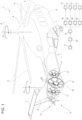
Figure 1 is a perspective view of a helicopter with a plurality of rotors manufactured according to the teachings of the present invention; -
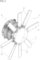
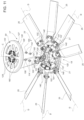
Figure 2 is a perspective view according to a first visual angle of the rotor ofFigure 1 on a greatly enlarged scale; -
Figure 3 is a perspective view according to a further visual angle of the rotor ofFigure 2 , with parts removed for clarity; -
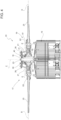
Figure 4 is a partial section along line IV-IV ofFigure 3 of some details of the rotor ofFigures 2 to 3 in a first operating position; -
Figure 5 illustrates on an enlarged scale some details ofFigure 4 ; -
Figure 6 illustrates on a still further enlarged scale and in section along line IV-IV ofFigure 2 some details of the rotor ofFigures 2 and3 in a second operating position; -
Figure 7 is an exploded view of the rotor ofFigures 2 to 6 , with parts not illustrated for clarity; -
Figure 8 illustrates on a still further enlarged scale some details of the rotor ofFigures 2 to 7 ; -
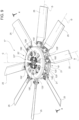
Figure 9 is a perspective view of a rotor according to a different embodiment of the invention; -
Figure 10 is a section along line X-X ofFigure 9 ; -
Figure 11 illustrates further details of the rotor ofFigures 9 and10 ; and -
Figure 12 qualitatively illustrates the time trend of some parameters of the rotor ofFigures 1 to 11 . - With reference to
Figure 1 , reference numeral 1 indicates a helicopter. - The helicopter 1 essentially comprises:
- a
fuselage 2 with anose 3 arranged at the front; - a drive unit 12 (only schematically illustrated in
Figure 1 ); - a
main rotor 4 provided with a plurality ofblades 11 placed at the top of thefuselage 2, operated by thedrive unit 12 and rotatable around an axis A; - a
tail portion 5 arranged on the opposite side of thefuselage 2 with respect to thenose 3 and comprising afin 6 and atailplane 7 protruding cantilevered from both sides of thefin 6; and - an
anti-torque system 10 carried by thetail portion 5. - As is known, the operation of the
rotor 4 allows adjusting the lift acting on the helicopter 1 and consequently varying the altitude of the helicopter 1. - In a known manner, the
blades 11 are articulated so as to be able to vary the inclination of the rotor disc, i.e. of the ideal disc defined by the free ends of theblades 11 opposite the axis A. - In such manner, the
rotor 4 controls the forward/backward movement and the lateral shifting of the helicopter 1. - The rotation of the
blades 11 around the axis A determines the application of a first torque C1 on thefuselage 2. Such first torque C1 would tend to determine the rotation of the helicopter 1 around the axis A. - The
anti-torque system 10 is provided for generating a second torque C2 of adjustable modulus and having a main component with a direction opposite the first torque C1, so as to be able to adjust the yaw angle of the helicopter 1. - When the main component of such second torque C2 is of modulus equal to the first torque C1, the
anti-torque system 10 prevents the rotation of the helicopter 1 around a yaw axis substantially parallel to the axis A and passing through the centre of gravity of the helicopter 1. - When the main component of such second torque C2 is of modulus smaller or greater than the first torque C1, the
anti-torque system 10 determines a variation of the yaw angle of the helicopter 1, i.e. the rotation of the helicopter 1 with respect to the yaw axis. - In some manoeuvres to be performed in a particularly quick time, the
anti-torque system 10 generates a second torque C2 in accordance with the first torque C1, so as to quickly rotate the helicopter 1 in the same direction of the first torque C1. - The
anti-torque system 10 comprises (Figure 1 ): - an electric power supply unit 15 (only schematically illustrated);
- a plurality of electric motors 16 (only schematically illustrated) operated by the
unit 15; and - a plurality of
rotors 17 operatively connected torespective motors 16 and operated by themotors 16. - The
unit 15 could comprise an electric energy generator operatively connected to thedrive unit 12, could comprise a plurality of batteries, or could be any electric energy source whatsoever. - In particular, the
unit 15 and therotors 17 could be connected so as to allow a bidirectional flow of electric energy/power. - In the following, one
single rotor 17 is described with reference to therelative motor 16, being therotors 17 and therespective motors 16 identical to one another. - With reference to
Figures 2 to 8 , therotor 17 essentially comprises, in turn: - a
shaft 18 rotatable around an axis C and coming out of themotor 16; - a
hub 19 rotatable around the axis C, coupled to theshaft 18 and on which a plurality, eight in the illustrated case, ofblades 25 are articulated extending along respective axes D transversal to the axis C; and - a controlling
element 20 also rotatable around the axis C. - In the following of the present description, the term "hub" means a component of the
rotor 17 rotatable around the axis C integrally with theblades 25 in every operating condition of therotor 17. - The
shaft 18 is driven into rotation by themotor 16 with an acceleration a of adjustable modulus. - The controlling
element 20 is spaced apart from thehub 19 parallel to the axis C. - The
rotor 17 further comprises: - a plurality of
connection members 21 hinged to the controllingelement 20 and torespective blades 25 around axes parallel to one another; and - constraining means 23 adapted to constrain the
hub 19 and the controllingelement 20 to one another. - Advantageously, the
connection members 21 are operable for determining the rotation of theblades 25 around the respective axes D, so as to adjust the respective angles of attack α, β, γ (Figure 12 );
the constrainingmeans 23 are configured to: - keep the
controlling element 20 andhub 19 angularly integral with one another around the axis C and in a first relative position (Figures 4 and5 ) with respect to one another, when the absolute value of the acceleration a of theelectric motor 16 is smaller than a threshold value Ta, so that the angles of attack α, β, γ assume respective first values α; - keep the
controlling element 20 andhub 19 angularly integral with one another around the axis C and in a second relative position (Figure 6 ) with respect to one another, when the absolute value of the acceleration a of theelectric motor 16 is greater than a threshold value Ta, so that the angles of attack α, β, γ assume respective second values β; and - allow the relative rotation between the controlling
element 20 andhub 19 between the aforementioned first and second positions when the absolute value of the acceleration a reaches the threshold value Ta. - More specifically, the
connection members 21 are rods each having: - an
end 22 slidable inside arespective seat 26 of the controllingelement 20; and - an
end 24 opposite theend 22 hinged to therelative blade 25 around an axis E eccentric with respect to the axis D of therelative blade 25. - The rotation of the
hub 19 relative to the controllingelement 20 around the axis C determines the rotation of theblades 25 around the relative axes D and the consequent variation of the angle of attack α, β, γ of theblades 25 between the aforementioned first value α, second value β and a third value γ not illustrated inFigure 12 . - With reference to
Figures 4 and5 , theshaft 18 is angularly integral with the controllingelement 20. - The
hub 19 has a first moment of inertia around the axis C greater than a second moment of inertia around the axis C of the controllingelement 20. - Consequently, when the absolute value of the acceleration a reaches the threshold value Ta, in case of rotation in the first (second) direction of the
output shaft 18, the inertia torque acting on thehub 19 tends to determine a relative rotation resulting in a backward movement of thehub 19 with respect to theoutput shaft 18 with reference to the first (second) direction of rotation for an observer integral with thefuselage 2 and, therefore, rotationally fixed with respect to the axis C. - Such backward movement of the
hub 19 in the first (second) direction corresponds to a forward movement of thehub 19 in the second (first) direction of rotation around the axis C. - The constraining means 23 essentially comprise (
Figures 4 to 8 ): - a
bushing 30 angularly fixed and axially movable with reference to the axis C with respect to theshaft 18, and provided with a plurality ofteeth 31 with a mainly axial development; and - a plurality of
projections 35 protruding cantilevered from thehub 19 and adapted to define respective abutment surfaces for correspondingteeth 31. - More specifically, the
bushing 30 is coupled to theshaft 18 by means of agrooved profile 32. - The
bushing 30 comprises, in turn (Figure 8 ): - a
flange 41 of axial end delimiting thebushing 30 on the side of the controllingelement 20 and from which a plurality, eight in the illustrated case, ofteeth 31 axially protrude cantilevered towards thehub 19; and - a
tubular body 42 protruding cantilevered from theflange 41 towards thehub 19 and on the radially internal lateral surface of which thegrooved profile 32 is obtained. - The
rotor 17 further comprises: - a plurality of
rings 40 made of elastically deformable material and axially interposed between thebushing 30 and theshaft 18; and - a
cylindrical ring 45 and a truncated cone-shapedring 46 fit on theshaft 18 in a position axially interposed between the controllingelement 20 and therings 40. - In particular, the
rings 40 are coaxial to the axis C and axially superimposed with respect to one another. - The
ring 45 is arranged on the side of the controllingelement 20 and thering 46 is arranged on the side of therings 40. - The
rings 40 are arranged in abutment against one another. - The
ring 40 axially closest to the controllingelement 20 is arranged in abutment against thering 46. - The
ring 40 axially closest to thebushing 30 is arranged in abutment against theflange 41. - With particular reference to
Figure 7 , thehub 19 comprises: - a radially internal
circular rim 60 passed through by theshaft 18 and by thebushing 30; - a radially external
circular rim 61 opposite thecircular rim 60 and passed through by theblades 25; and - a plurality, eight in the illustrated case, of pairs of
spokes 62, radially extending between thecircular rims respective seats 63 engaged by correspondingblades 25. - With reference to
Figure 8 , theprojections 35 are carried by thecircular rim 60. - Each
projection 35 is associated with arespective blade 25 and a correspondingtooth 31. - The
projections 35 are arranged in sequence with respect to one another, proceeding circumferentially around the axis C. - Each
projection 35 comprises, in particular (Figure 8 ): - a
flat surface 80 orthogonal to the axis C; and - three
concave surfaces 81 and twoconvex surfaces 82 circumferentially alternated with respect to one another around the axis C. - The
surface 80 is arranged at a first distance from the controllingelement 20, parallel to the axis C. - The
surfaces 81 are arranged at a second distance greater than said first distance from the controllingelement 20, parallel to the axis C. - The
surfaces 82 are arranged at a third intermediate distance between the first and second distances from the controllingelement 20, parallel to the axis C. - When the absolute value of the acceleration a of the
shaft 18 is smaller than the threshold value Ta, theteeth 31 of thebushing 30 are in axial abutment against thesurfaces 82 of the correspondingprojections 35 according to what is illustrated inFigures 4 and5 . - When the absolute value of the acceleration a is smaller than the threshold value Ta, the relative position between each axis E and the
relative seat 26 of the controllingelement 20 is such that the angle of attack α, β of theblades 25 assumes the first value α. - The
rings 40 are elastically deformed so as to be tapered starting from thebushing 30 towards thering 46. - More in particular, the
hub 19 is driven into rotation by the torque caused by the friction existing between thesurfaces 82 of theprojections 35 and the correspondingteeth 31. - In such condition, the torque caused by the friction in accordance with the direction of rotation of the
shaft 18 around the axis C exceeds the inertia torque acting on thehub 19 not in accordance with the aforementioned direction of rotation. - Upon the reaching of the threshold value Ta, the inertia torque exceeds the torque caused by the friction.
- Consequently, the
surfaces 82 move backward with respect to therespective teeth 31, and correspondingly thehub 19 moves backward with respect to theshaft 18 and the controllingelement 20, with reference to the direction of rotation around the axis C. - Then, the
teeth 31 of thebushing 30 axially abut against thesurfaces 80 of the correspondingprojections 35, according to what is illustrated inFigure 6 . - In such condition, the
hub 19 and theshaft 18 are again angularly integral with one another around the axis C. - When the acceleration a of the
shaft 18 is greater than the threshold value Ta, the relative position between axis E and theseat 26 of the controllingelement 20 is such that the angle of attack α, β, γ of theblades 25 assumes the second value β. - The
rings 40 are further substantially elastically undeformed so as to be flat and orthogonal to the axis C. - Still with reference to
Figures 4 and5 , in a further range of values of acceleration a of theshaft 18 not illustrated inFigure 12 , theteeth 31 of the controllingelement 20 are in abutment against thesurfaces 81 of therespective projections 35. - In such condition, the
hub 19 and theshaft 18 are again angularly integral with one another around the axis C. - In such further range, the relative position between axis E and
seat 26 of the controllingelement 20 is such that the angle of attack α, β, γ of theblades 25 assumes the third value γ. -
Figure 12 illustrates, in an exemplifying and non-limiting manner, the time course of the acceleration a of theoutput shaft 18, of the value of the angle of attack α, β of theblades 25, of the instantaneous rotational speed ω of theshaft 18, of the current i supplying theelectric motor 16, and threshold value Ta of the acceleration a according to a particular control law of theelectric motor 15. - Without any loss of generality, the control law provides for varying the angle of attack α, β, γ of the
blades 25 between the sole values α, β opposite one another. - In use, the operation of the
rotor 4 allows the lifting/lowering, the forward/backward movement and the lateral shifting of the helicopter 1. - The operation of the
rotor 4 generates the first torque C1 on thefuselage 2, which would determine the rotation of the helicopter 1 around the yaw axis. - The operation of the
anti-torque system 10 generates a second torque C2 on thefuselage 2 in a direction opposite the first torque C1. - Such second torque C2 determines the yaw angle of the helicopter 1.
- More specifically, the
unit 15 controls theelectric motors 16, so as to determine the rotation of therespective rotors 17 with respective directions of rotation and respective rotational speeds ω. - In such manner, the
rotors 17 generate respective forces on thefuselage 2 and, therefore, theanti-torque system 10 generates the second torque C2. - The difference between the second torque C2 and the first torque C1 adjusts the yaw angle of the helicopter 1.
- The operation of the helicopter 1 is described in the following with reference to one
single rotor 17 and to the relativeelectric motor 16. - The operation of the helicopter 1 is also described starting from a condition in which the angular speed ω of the
shaft 18 is directed in the first direction, and the absolute value of the acceleration a of theshaft 18 is smaller than the threshold value Ta and the angles of attack α, β, γ of theblades 25 assume a first value α (Figure 12 ). - In such condition, the
teeth 31 of thebushing 30 are in axial abutment against thesurfaces 82 of the correspondingprojections 35 according to what is illustrated inFigures 4 and5 . - The
rings 40 are elastically deformed so as to be tapered starting from thebushing 30 towards thering 46. Therefore, therings 40 elastically load thebushing 30 and therespective teeth 31 against thesurfaces 82 of the correspondingprojections 35. - More in particular, the
hub 19 is driven into rotation integrally with theshaft 18 by the torque caused by the friction existing between thesurfaces 82 of theprojections 35 and the correspondingteeth 31. - In such condition, the torque caused by the friction in accordance with the direction of rotation of the
shaft 18 around the axis C exceeds the inertia torque acting on thehub 19 not in accordance with the aforementioned direction of rotation. - Upon the reaching of the threshold value Ta, the inertia torque exceeds the torque caused by the friction.
- Consequently, the
surfaces 82 move backward with respect to therespective teeth 31, and correspondingly thehub 19 moves backward with respect to theshaft 18 and the controllingelement 20, with reference to the rotation of theshaft 18 in the first direction around the axis C. - The backward movement of the
hub 19 with respect to theshaft 18 determines the backward movement of the axis E with respect to theend 22 with reference to the rotation around the axis C. - This determines the variation of the angle of attack α, β, γ of the
blades 25 from the first value α to the second value β. - In the following, the
teeth 31 of thebushing 30 axially abut against thesurfaces 80 of the correspondingprojections 35, according to what is illustrated inFigure 6 . - In such condition, the
hub 19 and theshaft 18 are again angularly integral with one another around the axis C. - When the absolute value of the acceleration a of the
shaft 18 exceeds the threshold value Ta, therings 40 are substantially elastically undeformed so as to be flat and orthogonal to the axis C. - In a further range of values of acceleration a of the
shaft 18 not illustrated inFigure 12 , theteeth 31 of the controllingelement 20 are in abutment against thesurfaces 81 of therespective projections 35. - In such condition, the
hub 19 and theshaft 18 are again angularly integral with one another around the axis C. - In the following, by way of mere non-limiting example, some strategies for controlling the thrust generated by the
rotor 17 are described. - For example, starting from a condition in which the angle of attack α, β, γ is positive - i.e. is such that the
rotor 17 generates a thrust in a third direction - and theshaft 18 rotates in the first direction of rotation, it is possible to invert the direction of rotation of the thrust of therotor 17, reducing the acceleration a of theshaft 18 to a negative value smaller than -Ta. Consequently, theoutput shaft 18 rotates in the second direction of rotation around the axis C and thehub 19 angularly moves forward with respect to theshaft 18 with reference to the first direction of rotation around the axis C and, therefore, is angularly moved forward with respect to theshaft 18 still with reference to the first direction of rotation around the axis C. - The variation of the angle of attack α, β, γ of the
blades 25 up to the second negative value is thus determined, i.e. such that therotor 17 generates a thrust in a fourth direction opposite the third direction. - Then, the acceleration a of the
shaft 18 increases from the negative value up to a positive value smaller than the threshold value Ta, so as to bring the rotational speed ω of theshaft 18 to a positive value, i.e. in accordance with the first direction of rotation, and keep the thrust of therotor 17 in the fourth direction. - Alternatively, starting from a condition in which the first value of the angle of attack α, β, γ is negative, and the
shaft 18 rotates in the second direction of rotation, it is possible to reduce the rotational speed ω of theshaft 18, so as to reduce the aerodynamic forces acting on theblades 25 of therotor 17. - Then, the acceleration a of the
shaft 18 is brought to a value greater than Ta, i.e. in accordance with the first direction of rotation around the axis C, so that thehub 19 moves backward with respect to the controllingelement 20 with reference to the aforementioned first direction of rotation. - The variation of the angle of attack α, β, γ of the
blades 25 up to the second positive value and the inversion of the thrust generated by therotor 17 from the third direction of rotation to the fourth direction of rotation are thus determined. - With reference to
Figures 9 to 11 , reference numeral 17' indicates a rotor according to a different embodiment of the invention. - The rotor 17' is similar to the
rotor 17 and will be described in the following only with regard to what differs from the later; identical or equivalent parts of therotors 17, 17' will be indicated, if possible, by the same reference numerals. - In particular, the rotor 17' differs from the
rotor 17 due to the fact that: - the
shaft 18 is angularly integral with the hub 19' around the axis C; - the moment of inertia of the controlling element 20' is greater than the moment of inertia of the hub 19' with reference to the rotation around the axis C; and
- the controlling element 20' angularly moves backward with respect to the hub 19' with reference to the rotation around the axis C in the first (second) direction, when the threshold value Ta of the acceleration a of the
shaft 18 reaches the threshold value Ta. - The rotor 17' further differs from the
rotor 17 due to the fact that the hub 19' comprises (Figure 10 ): - an axial end flange 120' fixed to the
shaft 18 and with a bell-shaped body facing the controlling element 20'; - an axial end flange 121' opposite the flange 120'; and
- a tubular body 122' axially interposed between the flanges 120', 121'.
- The controlling element 20' is shaped like a flywheel essentially comprising:
- a radially internal circular rim 126' delimiting a hole 125' of axis C;
- a radially external circular rim 127' from which an annular edge 128' protrudes facing the
shaft 18; and - a plurality of spokes 129' radially extending between the circular rims 126', 127'.
- The rotor 17' further comprises:
- a tubular element 130' coaxially accommodated inside the tubular body 122', so as to result rotatable around the axis C integrally with the hub 19' and passing through the hole 125' of the controlling element 20' with a radial clearance; and
- a bearing 131' accommodated inside the hole 125' and radially interposed between the tubular element 130' and the tubular body 122'.
- The rotor 17' further comprises a nut 132' screwed on a thread 133' of the tubular element 130' arranged at an axial end of the tubular element 130' opposite the
shaft 18. - The nut 132' is in axial abutment against the controlling element 20' so as to make the
shaft 18 and the controlling element 20' axially integral with one another with respect to the axis C. - Each connection member 21' further comprises a pinion 140' carried by the
relative blade 25. In the illustrated case, the pinion 140' is a cone-shaped pinion. - The controlling element 20' further comprises a toothing 141' facing the pinion 140' and meshing with the pinion 140'.
- The hub 19' further comprises a toothing 142' carried by the flange 121', facing the pinion 140' and meshing with the pinion 140' on the opposite side of the toothing 141'.
- The coupling between the toothings 141', 142' and the relative pinions 140' holds the
blades 25 in the correct radial position with respect to the hub 19' against the action of the centrifugal force, thanks to the fact that the hub 19' and the controlling element 20' are axially integral with one another. - When the controlling element 20' and the hub 19' are angularly integral with one another around the axis C in the first and second positions, the coupling between the toothings 141', 142' and the relative pinions 140' determines the rotation of the
blades 25 around the axis C integrally with the output shaft 18' and the hub 19'. - When the controlling element 20' rotates with respect to the axis C from the first position to the second position, the pinions 140' rotate around the relative axes D due to the meshing with the toothing 141' consequently varying the angles of attack α, β of the
corresponding blades 25. - In other words, the controlling element 20' differs from the controlling
element 20 due to the fact of comprising the toothings 141', 142' and the pinions 140'. - The constraining means 23' differ from the constraining means 23 due to the fact of comprising (
Figures 10 and11 ): - a plurality of angularly fixed pins 100' axially movable with respect to the controlling element 20' and with reference to the axis C; and
- a plurality, four in the illustrated case, of pairs of seats 101', 102' defined by the hub 19' and open towards the controlling element 20'.
- In particular, the seats 101', 102' are obtained on the flange 120' of the hub 19'.
- Each pair of seats 101', 102' is associated with a respective pin 100'.
- The pairs of seats 101', 102' are angularly equally spaced apart around the axis C.
- The angle between homologous points of the seats 101', 102' of the same pair is smaller than the angle between homologous points of seats 101' (or 102') immediately consecutive with respect to one another, with reference to the axis C.
- The seats 101', 102' define respective surfaces 103', 104' shaped as respective hemispheres open towards the controlling
element 20. - Each pin 100' comprises, in turn:
- a stem 110' elongated parallel to the axis C;
- an axial end head 111' arranged on the side of the hub 19', shaped like a hemisphere and engaging the respective seat 101', 102';
- an end 112' opposite the head 111' and accommodated inside a respective seat 113' defined by the controlling element 20'; and
- an appendage 114' radially protruding from the stem 110' in a position axially interposed between the respective head 111' and end 112'.
- The rotor 17' further comprises a plurality of cup-shaped springs 115', axially interposed between the appendage 114' of the relative pin 100' and the controlling element 20'.
- In the illustrated case, the rotor 17' comprises a plurality, four in the illustrated case, of
inserts 180' fixed to the controlling element 20' in respective positions angularly equally spaced apart around the axis C. Eachinsert 180' accommodates a relative pin 100' and the relative spring 115'. - The operation of the rotor 17' is similar to that of the
rotor 17 and is described in the following only with regard to what differs from therotor 17. - In particular, the operation of the rotor 17' differs from the operation of the
rotor 17 due to the fact that theshaft 18 drives the hub 19' into rotation around the axis C. - The
shaft 18 is further axially integral with the controlling element 20', thanks to the fact that the nut 132' is screwed on the thread 133' of the tubular element 130' and is axially arranged in abutment against the controlling element 20'. - The coupling between the toothings 141', 142' and the relative pinions 140' holds the
blades 25 in the correct radial position with respect to the hub 19' against the action of the centrifugal force. - When the absolute value of the acceleration a of the
shaft 18 is smaller than the threshold value Ta, the controlling element 20' and the hub 19' are angularly integral with one another around the axis C in the first position, thanks to the fact that the pins 100' are accommodated in the seats 101' and kept inside them by the springs 115'. - More in particular, when the absolute value of the acceleration a is smaller than the threshold value Ta, the controlling element 20' is driven into rotation integrally with the
shaft 18 by the torque caused by the friction existing between the pins 100' and the seats 101'. - In such condition, the torque caused by the friction in accordance with the direction of rotation of the
shaft 18 around the axis C exceeds the inertia torque acting on the controllingelement 20 not in accordance with the aforementioned direction of rotation. - When the absolute value of the acceleration a reaches the threshold value Ta, the inertia torque exceeds the torque caused by the friction.
- Consequently, the pins 100' move away parallel to the axis C from the respective seats 101' against the action of the respective springs 115' and once they come out of the seats 101' they move backward integrally with the controlling element 20' with respect to the hub 19' with reference to a rotation around the axis C in the first direction.
- The backward movement of the controlling element 20' with respect to the hub 19' determines the backward movement of the toothing 141' with respect to the relative pinions 140', with reference to the rotation around the axis D.
- The pinions 140' thus rotate around the relative axes D due to the meshing with the toothing 141' consequently varying the angles of attack α, β of the
corresponding blades 25 from the first value to the second value. - Then, the pins 100' are pushed inside the seats 102' by the springs 115'.
- In such condition, the controlling
element 20 and theshaft 18 are again angularly integral with one another around the axis C. - By examining a
rotor 17; 17' according to the present invention, the advantages that the later allows obtaining are evident. - More specifically, the
hub 19; 19' and the controllingelement 20; 20' of therotor 17; 17' are angularly integral with one another around the axis C in the first position and in the second position when the value of the acceleration a of theoutput shaft 18 is smaller than the threshold value Ta, are angularly movable with respect to one another between the first and second positions when the absolute value of the acceleration a reaches and exceeds the threshold value Ta. - In such manner, it is possible to exploit the relative angular shifting between
hub 19; 19' andoutput shaft 18 for varying the angle of attack α, β, γ; α, β of theblades 25 between the first value α and the second value β. - It is thus possible to adjust the
rotor 17; 17' so as to generate a first thrust value parallel to the axis C at the first value α of the angle of attack α, β, γ; α, β of theblades 25 and a second thrust value parallel to the axis C at the second value β of the angle of attack α, β, γ; α, β of theblades 25, varying the rotational speed ω of theshaft 18 only for limited time intervals. Alternatively, it is possible to keep the thrust value generated by therotor 17; 17' constant by varying the rotational speed ω of theshaft 18, unlike the rotor solutions with fixed angles of attack discussed in the introduction of the present description. - Furthermore, the direction of the thrust of the
rotor 17; 17' can be easily inverted by simply configuring theconnection members 21; 21', so that the first value α of the angle of attack α, β, γ; α, β of theblades 25 is positive (negative) and the second value β of the aforementioned angle of attack α of theblades 25 is negative (positive). It is thus not necessary to invert the direction of rotation of theshaft 18 and consequently exchange the leading edge and the trailing edge of theblades 25. - With reference to the
rotor 17, theteeth 31 are kept by therings 40 in abutment against thesurfaces projections 35, when the absolute value of the acceleration a of theshaft 18 is respectively smaller or greater than the threshold value Ta. - With reference to the rotor 17', the pins 100' are kept by the respective springs 115' inside the respective seats 101', 102', when the absolute value of the acceleration a of the
shaft 18 is respectively smaller or greater than the threshold value Ta. - In such manner, it is possible to limit the relative angle of rotation between
hub 19, 19' and controllingelement 20, 20', thus also limiting the variation of the angle of attack α of theblades 25 between the first, second and third values α, β, γ for therotor 17 or between the first and second values α, β for the rotor 17'. - Finally, the mass of the
hub 19 and the mass of the controlling element 20' besides generating the greater first and second moments of inertia respectively around the axis C also have a structural function of supporting the aerodynamic loads acting on theblades 25. - It is thus possible to minimize the mass of the
rotor 17; 17' so as to raise the quickness of variation of the angle of attack α, β, γ; α, β between the aforementioned first value α and second value β, simultaneously raising the payload, the total mass of the helicopter 1 at take-off being equal. - It is clear that modifications and variations can be made to the
rotors 17, 17' described and illustrated herein without thereby departing from the scope of protection defined by the claims. - In particular, the angles of attack α, β, γ; α, β of the
blades 25 of therotors 17, 17' could assume any number whatsoever, specifically greater than two, of discrete values different from one another. - Furthermore, the
rotor 17, 17' could be used in a convertiplane. In such case, the axis C would be inclinable around an axis parallel to a transversal axis of the convertiplane between: - a position parallel to a longitudinal axis of the convertiplane assumed when the convertiplane is in the "airplane" position; and
- a position parallel to an axis orthogonal to the longitudinal and transversal axes of the convertiplane assumed when the convertiplane is in the "helicopter" position.
- Furthermore, the
rotor 17, 17' could be used in an aircraft having multiple rotors. In such case, the axis C could be fixed or inclinable so as to allow the aircraft to assume both an "airplane" position and a "helicopter" position.
Claims (15)
- A rotor (17, 17') for an aircraft (1) capable of hovering, comprising:- a motor element (16) comprising, in turn, an output shaft (18) rotatable around a first axis (C) and controllable so as to drive said output shaft (18) into rotation with an acceleration (a) selectively adjustable over time;- a hub (19, 19') rotatable around said first axis (C) and operatively connected to said output shaft (18);- at least two blades (25) rotatable integrally with said hub (19, 19') around said first axis (C);- at least two connection members (21, 21') operatively connected to said respective blades (25) and operable to determine the rotation of said respective blades (25) around said corresponding second extension axes (D) of the blades (25) transversal to said first axis (C), so as to adjust the angles of attack (α, β, γ; α, β) of said blades (25);- a controlling element (20, 20') connected to said connection members (21, 21') and rotatable around said first axis (C); and- constraining means (23, 23') adapted to constrain said hub (19, 19') and controlling element (20, 20') to one another in a movable manner;characterized in that said connection members (21, 21') are constrained to said blades (25) and to said controlling element (20, 20') so as to associate the value of said angle of attack (α, β, γ; α, β) with the relative angular position between said hub (19, 19') and said controlling element (20, 20'), with reference to said first axis (C);said constraining means (23, 23') being configured to:- keep said controlling elements and hub (20, 19; 20', 19') angularly integral with one another around said first axis (C) and in at least a first relative position with respect to one another, when the absolute value of said acceleration (a) is smaller, in use, than a threshold value (Ta), so that said angles of attack (α, β, γ; α, β) assume respective first values (α);- keep said controlling element and hub (20, 19) angularly integral with one another around said first axis (C) and in at least a second relative position with respect to one another angularly spaced apart from said first position, when the absolute value of said acceleration (a) is greater, in use, than a threshold value (Ta), so that said angles of attack (α, β, γ; α, β) assume respective second values (β) different from said first values (α); and- allow the relative rotation between said controlling element and hub (20, 19; 20', 19') between said first and second positions when the absolute value of said acceleration (a) reaches, in use, said threshold value (Ta).
- The rotor according to claim 1, characterized in that said output shaft (18) is angularly integral with one (20, 19') of said controlling element (20, 20') and said hub (19, 19');said one (20, 19') of said controlling element (20, 20') and said hub (19, 19') having a first moment of inertia around said first axis (C);said other one (19, 20') of said controlling element (20, 20') and said hub (19, 19') having a second moment of inertia around said first axis (C) different from, in particular greater than, said first moment of inertia.
- The rotor according to claim 1 or 2, characterized in that said constraining means (23, 23') comprise:- at least one projection (31, 100') angularly integral with one (20, 19') of said controlling element (20, 20') and hub (19, 19');- at least a first surface (80, 101') and a second surface (82, 102') angularly integral with the other one (19, 20') of said controlling element (20, 20') and hub (19, 19');said first and second surfaces (80, 101'; 82, 102') being angularly spaced apart from one another, proceeding circumferentially to said first axis (C);said first surface (80, 101') being in abutment against said projection (31, 100'), when said controlling element (20, 20') and hub (19, 19') are in said first position;said second surface (82, 102') being in abutment against said projection (31, 100'), when said controlling element (20, 20') and hub (19, 19') are in said second position;said projection (31) rotating angularly with respect to said first and second surfaces (80, 101'; 82, 102'), when said controlling elements (20, 20') and hub (19) are free to rotate with respect to one another.
- The rotor according to claim 2 or 3, characterized in that said output shaft (18) is angularly integral with said controlling element (20) around said first axis (C);said second moment of inertia of said hub (19) being greater than said first moment of inertia of said controlling element (20);said hub (19) being free to rotate with respect to said output shaft (18), in use, with reference to a direction of rotation of said output shaft (18), during said relative rotation between said first and second positions.
- The rotor according to claim 4, characterized in that it comprises a bushing (30) angularly integral and axially slidable with respect to said output shaft (18) around said first axis (C) and from which said projection (31) protrudes cantilevered parallel to said first axis (C) ;
said hub (19) defining said first and second surfaces (80, 82), which are axially staggered with respect to one another with reference to said first axis (C). - The rotor according to any one of claims from 3 to 5, characterized in that said connection members (21) each comprise a relative lever (21) slidable inside a relative seat (26) of said controlling element (20) and hinged to said corresponding blade (25).
- The rotor according to any one of claims from 4 to 6, characterized in that it comprises elastic means (40) interposed between said bushing (30) and said controlling element (20).
- The rotor according to claim 2 or 3, characterized in that said output shaft (18) is angularly integral with said hub (19') around said first axis (C);said first moment of inertia of said controlling element (20') being greater than said second moment of inertia of said hub (19');said controlling element (20') being free to rotate, in use, with respect to said output shaft (18), with reference to a direction of rotation of said output shaft (18), during said relative rotation between said first and second positions.
- The rotor according to any one of claims 2 or 8, when dependent on claim 2, characterized in that said hub (19') defines at least a first seat (101', 102') open parallel to said first axis (C) towards said controlling element (20');
said constraining means (23') further comprising:- at least one pin (100') defining said projection (31, 100') and engaging the first seat (101') defining said first surface (80, 101') when said controlling element (20') and hub (19') are arranged in said first position, and engaging said second seat (102') defining said second surface (102') when said controlling element (20') and hub (19') are arranged, in use, in said second position; and- elastic means (115') interposed between said controlling element (20') and said pin (100'). - The rotor according to any one of claims 1, 2, 8 or 9, characterized in that said hub (19') comprises a first toothing (141') and said controlling element (20') comprises a second toothing (142');each blade (25) comprising a toothed pinion (140') simultaneously meshing with said first and second toothings (141', 142');each connection member (21') comprising said second toothing (142') and said pinion (140') of said relative blade (25);said hub (19') and said controlling element (20') being axially integral with one another parallel to said first axis (C).
- The rotor according to any one of claims 1, 2 and from 8 to 10, characterized in that said motor element (16) is an electric motor.
- A helicopter comprising:- a fuselage (2);- a main rotor (4) operable to generate a force on said fuselage (2) adapted to support and manoeuvre the helicopter; and- a plurality of anti-torque rotors (17, 17'), at least one of which is manufactured according to any one of the preceding claims.
- A method for adjusting the angle of attack (α, β, γ; α, β) of the blades (25) of a rotor (17, 17') for an aircraft (1) capable of hovering;
said rotor (17, 17') comprising, in turn:- a motor element (16) comprising, in turn, an output shaft (18) rotatable around a first axis (C) and controllable so as to drive said output shaft (18) into rotation with an acceleration (a) selectively adjustable over time;- a hub (19, 19') rotatable around said first axis (C) and operatively connected to said output shaft (18);- at least two blades (25) rotatable integrally with said hub (19, 19') around said first axis (C);- at least two connection members (21, 21') operatively connected to respective blades (25) and operable to determine the rotation of said respective blades (25) around said corresponding second extension axes (D) of the blades (25) transversal to said first axis (C), so as to adjust the angles of attack (α, β, γ; α, β) of said blades (25);- a controlling element (20, 20') connected to said connection members (21, 21') and rotatable around said first axis (C); and- constraining means (23) adapted to constrain said hub (19, 19') and controlling element (20, 20') to one another in a movable manner;characterized in that it comprises the steps of:i) associating the value of said angles of attack (α, β, γ; α, β) with the relative angular position between said hub (19, 19') and said connection members (21, 21'), with reference to said first axis (C);ii) keeping said controlling elements and hub (20, 19; 20', 19') angularly integral with one another around said first axis (C) and in at least a first relative position with respect to one another, when the absolute value of said acceleration (a) is smaller, in use, than a threshold value (Ta), so that said angles of attack (α, β, γ; α, β) assume respective first values (α);iii) keeping said controlling element and hub (20, 19) angularly integral with one another around said first axis (C) and in at least a second relative position with respect to one another angularly spaced apart from said first position, when the absolute value of said acceleration (a) is greater, in use, than a threshold value (Ta), so that said angles of attack (α, β, γ; α, β) assume respective second values (β) different from said first values (α); andiv) allowing the relative rotation between said controlling element and hub (20, 19; 20', 19') between said first and second positions when the absolute value of said acceleration (a) reaches, in use, said threshold value (Ta). - The method according to claim 13, characterized in that step iv) comprises step v) of rotating said hub (19) with respect to said output shaft (18), with reference to a direction of rotation of said output shaft (18) during said step iv);
said connection members (21, 21') each comprising a relative lever (21) movable with respect to said controlling element (20) and hinged to said corresponding blade (25). - The method according to claim 13, characterized in that step iv) comprises step vi) of rotating said controlling element (20') with respect to said output shaft (18), with reference to a direction of rotation of the output shaft (18);said hub (19') comprising a first toothing (141') and said controlling element (20') comprising a second toothing (142');each of said blades (25) comprising a toothed pinion (140') simultaneously meshing with said first and second toothings (141', 142');each of said connection members (21') comprising said second toothing (142') and said pinion (140') of said relative blade (25);said hub (19') and said controlling element (20') being axially integral with one another parallel to said first axis (C).
Priority Applications (2)
| Application Number | Priority Date | Filing Date | Title |
|---|---|---|---|
| EP23220515.3A EP4578785B1 (en) | 2023-12-28 | 2023-12-28 | Rotor for an aircraft capable of hovering and method of adjustment of rotor blade angle pitch |
| PCT/IB2024/061839 WO2025141354A1 (en) | 2023-12-28 | 2024-11-26 | Rotor for an aircraft capable of hovering and method for adjusting the angle of attack of the blades of the aforementioned rotor |
Applications Claiming Priority (1)
| Application Number | Priority Date | Filing Date | Title |
|---|---|---|---|
| EP23220515.3A EP4578785B1 (en) | 2023-12-28 | 2023-12-28 | Rotor for an aircraft capable of hovering and method of adjustment of rotor blade angle pitch |
Publications (2)
| Publication Number | Publication Date |
|---|---|
| EP4578785A1 true EP4578785A1 (en) | 2025-07-02 |
| EP4578785B1 EP4578785B1 (en) | 2026-02-25 |
Family
ID=89897966
Family Applications (1)
| Application Number | Title | Priority Date | Filing Date |
|---|---|---|---|
| EP23220515.3A Active EP4578785B1 (en) | 2023-12-28 | 2023-12-28 | Rotor for an aircraft capable of hovering and method of adjustment of rotor blade angle pitch |
Country Status (2)
| Country | Link |
|---|---|
| EP (1) | EP4578785B1 (en) |
| WO (1) | WO2025141354A1 (en) |
Citations (5)
| Publication number | Priority date | Publication date | Assignee | Title |
|---|---|---|---|---|
| US5749540A (en) * | 1996-07-26 | 1998-05-12 | Arlton; Paul E. | System for controlling and automatically stabilizing the rotational motion of a rotary wing aircraft |
| EP2982604A1 (en) * | 2014-08-08 | 2016-02-10 | AGUSTAWESTLAND S.p.A. | Helicopter anti-torque rotor |
| US20160059960A1 (en) * | 2013-03-24 | 2016-03-03 | Michael Fearn | Semi-automatic collective pitch mechanism for a rotorcraft |
| EP3501983A1 (en) | 2017-12-22 | 2019-06-26 | LEONARDO S.p.A. | Anti-torque system for a helicopter and method for controlling an anti-torque system for a helicopter |
| US11554860B1 (en) * | 2020-06-23 | 2023-01-17 | Piasecki Aircraft Corporation | Apparatus, system and method for a convertible thruster for a compound aircraft |
-
2023
- 2023-12-28 EP EP23220515.3A patent/EP4578785B1/en active Active
-
2024
- 2024-11-26 WO PCT/IB2024/061839 patent/WO2025141354A1/en active Pending
Patent Citations (5)
| Publication number | Priority date | Publication date | Assignee | Title |
|---|---|---|---|---|
| US5749540A (en) * | 1996-07-26 | 1998-05-12 | Arlton; Paul E. | System for controlling and automatically stabilizing the rotational motion of a rotary wing aircraft |
| US20160059960A1 (en) * | 2013-03-24 | 2016-03-03 | Michael Fearn | Semi-automatic collective pitch mechanism for a rotorcraft |
| EP2982604A1 (en) * | 2014-08-08 | 2016-02-10 | AGUSTAWESTLAND S.p.A. | Helicopter anti-torque rotor |
| EP3501983A1 (en) | 2017-12-22 | 2019-06-26 | LEONARDO S.p.A. | Anti-torque system for a helicopter and method for controlling an anti-torque system for a helicopter |
| US11554860B1 (en) * | 2020-06-23 | 2023-01-17 | Piasecki Aircraft Corporation | Apparatus, system and method for a convertible thruster for a compound aircraft |
Also Published As
| Publication number | Publication date |
|---|---|
| EP4578785B1 (en) | 2026-02-25 |
| WO2025141354A1 (en) | 2025-07-03 |
Similar Documents
| Publication | Publication Date | Title |
|---|---|---|
| EP3501983B2 (en) | Anti-torque system for a helicopter and method for controlling an anti-torque system for a helicopter | |
| EP2832640B1 (en) | Composite flexure for tiltrotor rotor system | |
| KR102084072B1 (en) | A rotor assembly for a rotorcraft with torque controlled collective pitch | |
| EP3034399B1 (en) | Rotor assembly apparatus | |
| US11623744B2 (en) | Rotor for a hover-capable aircraft and related method of control | |
| EP2907747A1 (en) | Cyclic pitch actuation system for counter-rotating propellers | |
| US9604729B2 (en) | Aircraft control system and method | |
| US11724802B1 (en) | Lightweight rotor conversion systems for tiltrotor aircraft | |
| US6454532B1 (en) | Harmonic drive system for the retraction/extension of variable diameter rotor systems | |
| EP4578785B1 (en) | Rotor for an aircraft capable of hovering and method of adjustment of rotor blade angle pitch | |
| EP3878739B1 (en) | Bidirectional aircraft rotor | |
| US3756743A (en) | Rotors for rotary winged aircraft | |
| US12441465B2 (en) | Anti-backlash flight control actuator system | |
| EP3929077B1 (en) | Rotor for an aircraft capable of hovering | |
| CN116981620A (en) | aircraft capable of hovering | |
| CN112319762A (en) | Multidirectional attitude control device | |
| EP4603382A1 (en) | Rotor control for a convertible aircraft | |
| CN120646223A (en) | Internally-variable pitch propeller hub structure for tilting aircraft and tilting aircraft | |
| AU2021232803A1 (en) | Torqe actuated variable pitch rotor | |
| US2568363A (en) | Helicopter | |
| TR2022018726A1 (en) | An aircraft. | |
| GB1571998A (en) | Helicopter rotors |
Legal Events
| Date | Code | Title | Description |
|---|---|---|---|
| PUAI | Public reference made under article 153(3) epc to a published international application that has entered the european phase |
Free format text: ORIGINAL CODE: 0009012 |
|
| STAA | Information on the status of an ep patent application or granted ep patent |
Free format text: STATUS: REQUEST FOR EXAMINATION WAS MADE |
|
| 17P | Request for examination filed |
Effective date: 20240528 |
|
| AK | Designated contracting states |
Kind code of ref document: A1 Designated state(s): AL AT BE BG CH CY CZ DE DK EE ES FI FR GB GR HR HU IE IS IT LI LT LU LV MC ME MK MT NL NO PL PT RO RS SE SI SK SM TR |
|
| GRAP | Despatch of communication of intention to grant a patent |
Free format text: ORIGINAL CODE: EPIDOSNIGR1 |
|
| STAA | Information on the status of an ep patent application or granted ep patent |
Free format text: STATUS: GRANT OF PATENT IS INTENDED |
|
| INTG | Intention to grant announced |
Effective date: 20250711 |
|
| RIN1 | Information on inventor provided before grant (corrected) |
Inventor name: NOVEMBRINI, GIOVANNI Inventor name: DELLI PAOLI, MICHELE Inventor name: ZACCARIA, ALESSIO Inventor name: MANENTI, GIUSEPPE Inventor name: NESCI, ANDREA Inventor name: BRUNETTI, MASSIMO |
|
| GRAJ | Information related to disapproval of communication of intention to grant by the applicant or resumption of examination proceedings by the epo deleted |
Free format text: ORIGINAL CODE: EPIDOSDIGR1 |
|
| STAA | Information on the status of an ep patent application or granted ep patent |
Free format text: STATUS: REQUEST FOR EXAMINATION WAS MADE |
|
| GRAP | Despatch of communication of intention to grant a patent |
Free format text: ORIGINAL CODE: EPIDOSNIGR1 |
|
| STAA | Information on the status of an ep patent application or granted ep patent |
Free format text: STATUS: GRANT OF PATENT IS INTENDED |
|
| INTC | Intention to grant announced (deleted) | ||
| INTG | Intention to grant announced |
Effective date: 20250924 |
|
| GRAS | Grant fee paid |
Free format text: ORIGINAL CODE: EPIDOSNIGR3 |
|
| GRAA | (expected) grant |
Free format text: ORIGINAL CODE: 0009210 |
|
| STAA | Information on the status of an ep patent application or granted ep patent |
Free format text: STATUS: THE PATENT HAS BEEN GRANTED |
|
| AK | Designated contracting states |
Kind code of ref document: B1 Designated state(s): AL AT BE BG CH CY CZ DE DK EE ES FI FR GB GR HR HU IE IS IT LI LT LU LV MC ME MK MT NL NO PL PT RO RS SE SI SK SM TR |
|
| REG | Reference to a national code |
Ref country code: CH Ref legal event code: F10 Free format text: ST27 STATUS EVENT CODE: U-0-0-F10-F00 (AS PROVIDED BY THE NATIONAL OFFICE) Effective date: 20260225 Ref country code: GB Ref legal event code: FG4D |
|
| REG | Reference to a national code |
Ref country code: CH Ref legal event code: R17 Free format text: ST27 STATUS EVENT CODE: U-0-0-R10-R17 (AS PROVIDED BY THE NATIONAL OFFICE) Effective date: 20260227 |
|
| P01 | Opt-out of the competence of the unified patent court (upc) registered |
Free format text: CASE NUMBER: UPC_APP_0002476_4578785/2026 Effective date: 20260123 |
|
| REG | Reference to a national code |
Ref country code: DE Ref legal event code: R096 Ref document number: 602023012587 Country of ref document: DE |
|
| REG | Reference to a national code |
Ref country code: IE Ref legal event code: FG4D |