EP4578770A1 - Straddled vehicle - Google Patents
Straddled vehicle Download PDFInfo
- Publication number
- EP4578770A1 EP4578770A1 EP24171892.3A EP24171892A EP4578770A1 EP 4578770 A1 EP4578770 A1 EP 4578770A1 EP 24171892 A EP24171892 A EP 24171892A EP 4578770 A1 EP4578770 A1 EP 4578770A1
- Authority
- EP
- European Patent Office
- Prior art keywords
- vehicle
- ventilation hole
- disposed
- electronic control
- control unit
- Prior art date
- Legal status (The legal status is an assumption and is not a legal conclusion. Google has not performed a legal analysis and makes no representation as to the accuracy of the status listed.)
- Pending
Links
Images




Classifications
-
- B—PERFORMING OPERATIONS; TRANSPORTING
- B62—LAND VEHICLES FOR TRAVELLING OTHERWISE THAN ON RAILS
- B62J—CYCLE SADDLES OR SEATS; AUXILIARY DEVICES OR ACCESSORIES SPECIALLY ADAPTED TO CYCLES AND NOT OTHERWISE PROVIDED FOR, e.g. ARTICLE CARRIERS OR CYCLE PROTECTORS
- B62J17/00—Weather guards for riders; Fairings or stream-lining parts not otherwise provided for
- B62J17/10—Ventilation or air guiding devices forming part of fairings
-
- B—PERFORMING OPERATIONS; TRANSPORTING
- B62—LAND VEHICLES FOR TRAVELLING OTHERWISE THAN ON RAILS
- B62J—CYCLE SADDLES OR SEATS; AUXILIARY DEVICES OR ACCESSORIES SPECIALLY ADAPTED TO CYCLES AND NOT OTHERWISE PROVIDED FOR, e.g. ARTICLE CARRIERS OR CYCLE PROTECTORS
- B62J15/00—Mud-guards for wheels
-
- B—PERFORMING OPERATIONS; TRANSPORTING
- B62—LAND VEHICLES FOR TRAVELLING OTHERWISE THAN ON RAILS
- B62J—CYCLE SADDLES OR SEATS; AUXILIARY DEVICES OR ACCESSORIES SPECIALLY ADAPTED TO CYCLES AND NOT OTHERWISE PROVIDED FOR, e.g. ARTICLE CARRIERS OR CYCLE PROTECTORS
- B62J45/00—Electrical equipment arrangements specially adapted for use as accessories on cycles, not otherwise provided for
-
- B—PERFORMING OPERATIONS; TRANSPORTING
- B62—LAND VEHICLES FOR TRAVELLING OTHERWISE THAN ON RAILS
- B62K—CYCLES; CYCLE FRAMES; CYCLE STEERING DEVICES; RIDER-OPERATED TERMINAL CONTROLS SPECIALLY ADAPTED FOR CYCLES; CYCLE AXLE SUSPENSIONS; CYCLE SIDECARS, FORECARS, OR THE LIKE
- B62K11/00—Motorcycles, engine-assisted cycles or motor scooters with one or two wheels
-
- B—PERFORMING OPERATIONS; TRANSPORTING
- B62—LAND VEHICLES FOR TRAVELLING OTHERWISE THAN ON RAILS
- B62M—RIDER PROPULSION OF WHEELED VEHICLES OR SLEDGES; POWERED PROPULSION OF SLEDGES OR SINGLE-TRACK CYCLES; TRANSMISSIONS SPECIALLY ADAPTED FOR SUCH VEHICLES
- B62M7/00—Motorcycles characterised by position of motor or engine
Definitions
- the present invention relates to a straddled vehicle.
- the first ventilation hole is provided in the rear cover. Therefore, the electronic control unit inside the rear cover is efficiently cooled by air flowing in and out through the first ventilation hole. Further, the first ventilation hole is disposed facing outward in the left-right direction of the vehicle. Therefore, water or mud splashed up from the rear wheel is less likely to enter through the first ventilation hole, compared to a case where the first ventilation hole is disposed facing downward. This prevents water or mud from entering the rear cover.
- the first ventilation hole may be disposed below the electronic control unit as seen in a vehicle side view. At least a portion of the first ventilation hole may be disposed directly below the electronic control unit as seen in the vehicle side view. The first ventilation hole may be disposed outward of the electronic control unit in the left-right direction of the vehicle. Thereby, the electronic control unit inside the rear cover is efficiently cooled.
- the rear cover may include an inner rear fender and a rear side cover.
- the inner rear fender may be disposed below the internal space and may be disposed facing the rear wheel.
- the rear side cover may be disposed on a lateral side of the internal space.
- the first ventilation hole may be provided in the inner rear fender.
- the inner rear fender may include a curved surface and a first bulging portion.
- the curved surface may be curved convexly upward.
- the first bulging portion may bulge downward from the curved surface.
- the first ventilation hole may be provided in the first bulging portion. In this case, the first bulging portion allows the first ventilation hole to be easily provided so as to face outward in the left-right direction of the vehicle.
- the first ventilation hole may be provided in the rear side cover. In this case, the intrusion of water or mud into the rear cover is further suppressed.
- the rear cover may include a plurality of fins provided in the ventilation hole.
- the plurality of fins may be inclined with respect to the left-right direction of the vehicle.
- the plurality of fins may be inclined forward and outward in the left-right direction of the vehicle. In this case, the intrusion of water or mud into the rear cover is further suppressed.
- the rear cover may include a baffle plate.
- the baffle plate may be disposed inside the plurality of fins in the left-right direction of the vehicle. In this case, the intrusion of water or mud into the rear cover is further suppressed.
- FIG. 1 is a left side view of a straddled vehicle 1 according to an embodiment.
- the straddled vehicle 1 includes a vehicle body frame 2, a steering device 3, a fuel tank 4, a seat 5, a power unit 6, a front wheel 7, and a rear wheel 8.
- the front-rear, left-right, and up-down directions mean the front-rear, left-right, and up-down directions as seen from a rider seated on the seat 5.
- the vehicle body frame 2 includes a head pipe 11, a main frame 12, and a rear frame 13.
- the main frame 12 is connected to the head pipe 11.
- the main frame 12 extends rearward from the head pipe 11.
- the rear frame 13 extends diagonally rearward and upward from the main frame 12.
- the steering device 3 is rotatably supported by the head pipe 11.
- the steering device 3 rotatably supports the front wheel 7.
- the steering device 3 includes a steering shaft 14, a handle member 15, and a front fork 16.
- the steering shaft 14 is inserted into the head pipe 11.
- the handle member 15 is disposed above the head pipe 11.
- the handle member 15 extends in the left-right direction.
- the front fork 16 is connected to the steering shaft 14.
- the front fork 16 rotatably supports the front wheel 7.
- the fuel tank 4 is disposed behind the head pipe 11.
- the fuel tank 4 is supported by the main frame 12.
- the seat 5 is disposed behind the fuel tank 4.
- the seat 5 includes a main seat 5A and a tandem seat 5B.
- the tandem seat 5B is disposed behind the main seat 5A.
- the power unit 6 is disposed below the fuel tank 4.
- the power unit 6 is supported by the main frame 12.
- the power unit 6 includes, for example, an internal combustion engine.
- the rear wheel 8 is supported by the main frame 12 via a swing arm 17.
- the rear wheel 8 is rotatably supported by the swing arm 17.
- the swing arm 17 is supported by the main frame 12 so as to be able to swing up and down.
- the straddled vehicle 1 includes a rear cover 18.
- the rear cover 18 covers a part of the rear frame 13.
- the rear cover 18 is disposed behind the main seat 5A.
- the rear cover 18 is disposed below the tandem seat 5B.
- the rear cover 18 is disposed above the rear wheel 8.
- FIG. 2 is a left side view of the rear cover 18.
- FIG. 3 is a right side view of the rear cover 18.
- FIG. 4 is a top view of the rear cover 18.
- FIG. 5 is a bottom view of the rear cover 18.
- FIG. 6 is a rear view of the rear cover 18.
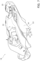
- FIGS. 7 and 8 are perspective views of the rear cover 18. Note that, as shown in FIG. 1 , a side panel 22 is attached to the rear cover 18, but the side panel 22 is omitted in FIGS. 2 to 8 .
- the rear cover 18 includes an internal space S1.
- the electronic control unit 20 is disposed in the internal space S1 of the rear cover 18.
- the rear cover 18 includes an inner rear fender 23, a left rear side cover 24, and a right rear side cover 25.
- the inner rear fender 23 is disposed below the internal space S1.
- the inner rear fender 23 covers the internal space S1 from below.
- the left rear side cover 24 is disposed on the left side of the internal space S1.
- the left rear side cover 24 covers the internal space S1 from the left side.
- the right rear side cover 25 is disposed on the right side of the internal space S1.
- the right rear side cover 25 covers the internal space S1 from the right side.
- the inner rear fender 23 is disposed directly above the rear wheel 8.
- the inner rear fender 23 is disposed facing the rear wheel 8.
- An outer rear fender 26 is disposed behind the inner rear fender 23.
- the outer rear fender 26 is connected to the rear frame 13 via a stay 27.
- the left rear side cover 24 extends upward from the inner rear fender 23.
- the left rear side cover 24 is disposed between the inner rear fender 23 and the tandem seat 5B in the vehicle vertical direction.
- the right rear side cover 25 is disposed apart from the left rear side cover 24 in the left-right direction of the vehicle.
- the right rear side cover 25 extends upward from the inner rear fender 23.
- the right rear side cover 25 is disposed between the inner rear fender 23 and the tandem seat 5B in the vehicle vertical direction.
- the left rear side cover 24 covers the electronic control unit 20 from the left side.
- the right rear side cover 25 covers the electronic control unit 20 from the right side.
- the electronic control unit 20 is disposed between the left rear side cover 24 and the right rear side cover 25 in the vehicle left-right direction. As shown in FIG. 2 , the left rear side cover 24 overlaps the electronic control unit 20 as seen in the vehicle side view. As shown in FIG. 3 , the right rear side cover 25 overlaps the electronic control unit 20 as seen in the vehicle side view.
- FIG. 9 is a sectional view taken along line IX-IX in FIG. 4 .
- the electronic control unit 20 includes a plurality of heat radiation fins 33.
- the heat radiation fins 33 extend downward from the unit body 28. Note that, in FIG. 9 , only one of the plurality of heat radiation fins 33 is designated by the reference numeral 33, and the reference numerals of the other heat radiation fins 33 are omitted.
- the inner rear fender 23 includes a curved surface 34, a first bulging portion 35, and a second bulging portion 36.
- the curved surface 34 has an upwardly curved shape.
- the curved surface 34 has a cross-sectional shape convexly curved upward as seen in the vehicle front view.
- the curved surface 34 is curved downward laterally outward from the center in the left-right direction of the vehicle.
- the curved surface 34 includes a center portion 37, a left side portion 38, and a right side portion 39.
- the center portion 37 is disposed on the vehicle center line C1 extending in the front-rear direction of the vehicle.
- the center portion 37 is disposed between the left side portion 38 and the right side portion 39 in the left-right direction of the vehicle.
- the electronic control unit 20 is disposed directly above the center portion 37.
- the electronic control unit 20 is disposed facing the center portion 37.
- the first bulging portion 35 and the second bulging portion 36 are disposed apart from each other in the left-right direction of the vehicle.
- the first bulging portion 35 and the second bulging portion 36 each bulge downward from the curved surface 34.
- the first bulging portion 35 has a shape that bulges downward as seen in the vehicle side view.
- the second bulging portion 36 has a shape that bulges downward as seen in the vehicle side view.
- the inner rear fender 23 includes a first ventilation hole 41 and a second ventilation hole 42.
- the first ventilation hole 41 and the second ventilation hole 42 communicate with the internal space S1.
- the first ventilation hole 41 and the second ventilation hole 42 extend from the outside of the rear cover 18 to the internal space S1 of the rear cover 18 through the inner rear fender 23.
- the second ventilation hole 42 is disposed laterally symmetrically with the first ventilation hole 41.
- the second ventilation hole 42 may be disposed laterally asymmetrically with respect to the first ventilation hole 41.
- at least a portion of the first ventilation hole 41 is located forward of the rotation axis X1 of the rear wheel 8.
- at least a portion of the second ventilation hole 42 is located forward of the rotation axis X1 of the rear wheel 8.
- the first ventilation hole 41 is provided in the first bulging portion 35.
- the first bulging portion 35 includes a first step portion 43.
- the first step portion 43 projects downward from the left side portion 38.
- the first ventilation hole 41 is provided in the first step portion 43.
- the second ventilation hole 42 is provided in the second bulging portion 36.
- the second bulging portion 36 includes a second step portion 44.
- the second step portion 44 projects downward from the right side portion 39.
- the second ventilation hole 42 is provided in the second step portion 44.
- the first ventilation hole 41 is disposed below the electronic control unit 20 as seen in the vehicle side view. At least a portion of the first ventilation hole 41 is disposed directly below the electronic control unit 20 as seen in the vehicle side view.
- the front end 41A of the first ventilation hole 41 is located rearward of the front surface 20A of the electronic control unit 20 as seen in the vehicle side view.
- the rear end 41B of the first ventilation hole 41 is located rearward of the rear surface 20B of the electronic control unit 20 as seen in the vehicle side view.
- the second ventilation hole 42 is disposed below the electronic control unit 20 as seen in the vehicle side view. At least a portion of the second ventilation hole 42 is disposed directly below the electronic control unit 20 as seen in the vehicle side view.
- the front end 42A of the second ventilation hole 42 is located rearward of the front surface 20A of the electronic control unit 20 as seen in the vehicle side view.
- the rear end 42B of the second ventilation hole 42 is located rearward of the rear surface 20B of the electronic control unit 20 as seen in the vehicle side view.
- the first ventilation hole 41 and the second ventilation hole 42 are disposed outward of the electronic control unit 20 in the left-right direction of the vehicle.
- the first ventilation hole 41 is disposed leftward of the electronic control unit 20 in the left-right direction of the vehicle.
- the second ventilation hole 42 is disposed rightward of the electronic control unit 20 in the left-right direction of the vehicle.
- FIG. 10 is an enlarged top view of the rear cover 18.
- the rear cover 18 includes a plurality of first fins 45 and a plurality of second fins 46. Note that in the drawings, only one of the plurality of first fins 45 is designated by the reference numeral 45, and the reference numerals of the other first fins 45 are omitted. Further, in the drawings, only one of the plurality of second fins 46 is designated by the reference numeral 46, and the reference numerals of the other second fins 46 are omitted.
- the plurality of first fins 45 and the plurality of second fins 46 protrude upward from the upper surface of the inner rear fender 23.
- the plurality of first fins 45 are disposed at intervals in the front-rear direction of the vehicle.
- the plurality of first fins 45 are provided in the first ventilation hole 41.
- the plurality of first fins 45 extend inward from the first ventilation hole 41 in the left-right direction of the vehicle.
- the plurality of first fins 45 are inclined forward and outward in the left-right direction of the vehicle.
- the rear cover 18 includes a first baffle plate 47 and a second baffle plate 48.
- the first baffle plate 47 and the second baffle plate 48 protrude upward from the upper surface of the inner rear fender 23.
- the first baffle plate 47 is disposed inside the plurality of first fins 45 in the left-right direction of the vehicle.
- the first baffle plate 47 is disposed to face the plurality of first fins 45 in the left-right direction of the vehicle.
- the front end 47A of the first baffle plate 47 is located forward of the front end 41A of the first ventilation hole 41.
- the rear end 47B of the first baffle plate 47 is located rearward of the rear end 41B of the first ventilation hole 41.
- the first baffle plate 47 has a shape that is curved inward in the left-right direction of the vehicle as seen in the vehicle top view.
- FIG. 11 is a left side view of the rear cover 18 according to a modified example. As shown in FIG. 11 , the first ventilation hole 41 may be provided in the left rear side cover 24. Although not shown in the drawings, the second ventilation hole 42 may be provided in the right rear side cover 25.
Landscapes
- Engineering & Computer Science (AREA)
- Mechanical Engineering (AREA)
- Automatic Cycles, And Cycles In General (AREA)
Abstract
Description
- The present invention relates to a straddled vehicle.
- Some straddled vehicles have an electronic control unit disposed within a rear cover disposed above the rear wheel. For example, in the straddled vehicle disclosed in
JP 2020- 164111 A - Since the electronic control unit generates heat, it is preferable that the electronic control unit is cooled by the running wind. However, when the electronic control unit is disposed within the rear cover, it is difficult to efficiently cool the electronic control unit due to the running wind. Further, when a ventilation hole is provided in the rear cover to cool the electronic control unit by the running wind while the vehicle is running, there is a concern that water or mud may enter the rear cover through the ventilation hole. In particular, since the rear cover is disposed close to the rear wheel, water or mud splashed up from the rear wheel tends to enter the rear cover through the ventilation hole.
- It is an object of the present invention to provide a straddled vehicle that can efficiently cool an electronic control unit within a rear cover and can prevent water or mud from entering the rear cover.
- According to the present invention said object is solved by a straddled vehicle having the features of
independent claim 1. Preferred embodiments are laid down in the dependent claims. - A straddled vehicle according to one aspect of the present teaching includes a rear wheel, a rear cover, and an electronic control unit. The rear cover includes an internal space and a first ventilation hole communicating with the internal space. The rear cover is disposed above the rear wheel. The electronic control unit is disposed in the internal space of the rear cover. The first ventilation hole is disposed facing outward in a left-right direction of the vehicle.
- In the straddled vehicle according to the present aspect, the first ventilation hole is provided in the rear cover. Therefore, the electronic control unit inside the rear cover is efficiently cooled by air flowing in and out through the first ventilation hole. Further, the first ventilation hole is disposed facing outward in the left-right direction of the vehicle. Therefore, water or mud splashed up from the rear wheel is less likely to enter through the first ventilation hole, compared to a case where the first ventilation hole is disposed facing downward. This prevents water or mud from entering the rear cover.
- The first ventilation hole may be disposed below the electronic control unit as seen in a vehicle side view. At least a portion of the first ventilation hole may be disposed directly below the electronic control unit as seen in the vehicle side view. The first ventilation hole may be disposed outward of the electronic control unit in the left-right direction of the vehicle. Thereby, the electronic control unit inside the rear cover is efficiently cooled.
- The rear cover may include an inner rear fender and a rear side cover. The inner rear fender may be disposed below the internal space and may be disposed facing the rear wheel. The rear side cover may be disposed on a lateral side of the internal space. The first ventilation hole may be provided in the inner rear fender.
- The inner rear fender may include a curved surface and a first bulging portion. The curved surface may be curved convexly upward. The first bulging portion may bulge downward from the curved surface. The first ventilation hole may be provided in the first bulging portion. In this case, the first bulging portion allows the first ventilation hole to be easily provided so as to face outward in the left-right direction of the vehicle.
- The inner rear fender may include a second bulging portion and a second ventilation hole. The second bulging portion may be disposed apart from the first bulging portion in the left-right direction of the vehicle. The second bulging portion may bulge downward from the curved surface. The second ventilation hole may be provided in the second bulging portion. The second ventilation hole may be disposed facing outward opposite to the first bulging portion in the left-right direction of the vehicle. In this case, the electronic control unit in the rear cover is efficiently cooled by air flowing in and out through the second ventilation hole. Furthermore, the second bulging portion allows the second ventilation hole to be easily provided so as to face outward in the left-right direction of the vehicle.
- The first ventilation hole may be provided in the rear side cover. In this case, the intrusion of water or mud into the rear cover is further suppressed.
- The rear cover may include a plurality of fins provided in the ventilation hole. The plurality of fins may be inclined with respect to the left-right direction of the vehicle. The plurality of fins may be inclined forward and outward in the left-right direction of the vehicle. In this case, the intrusion of water or mud into the rear cover is further suppressed.
- The rear cover may include a baffle plate. The baffle plate may be disposed inside the plurality of fins in the left-right direction of the vehicle. In this case, the intrusion of water or mud into the rear cover is further suppressed.
- The opening area of the first ventilation hole as seen in the vehicle side view may be larger than the opening area of the first ventilation hole as seen in a vehicle rear view. In this case, the electronic control unit in the rear cover is efficiently cooled by increasing the amount of air flowing in and out between the lateral side of the rear cover and the internal space. Furthermore, water or mud splashed up from behind the first ventilation hole by the rear wheel is prevented from entering the rear cover.
-
-
FIG. 1 is a left side view of a straddled vehicle according to an embodiment. -
FIG. 2 is a left side view of a rear cover. -
FIG. 3 is a right side view of the rear cover. -
FIG. 4 is a top view of the rear cover. -
FIG. 5 is a bottom view of the rear cover. -
FIG. 6 is a rear view of the rear cover. -
FIG. 7 is a perspective view of the rear cover. -
FIG. 8 is a perspective view of the rear cover. -
FIG. 9 is a sectional view taken along line IX-IX inFIG. 4 . -
FIG. 10 is an enlarged top view of the rear cover. -
FIG. 11 is a left side view of a rear cover according to a modified example. - Hereinafter, a straddled vehicle according to an embodiment will be described with reference to the drawings.
FIG. 1 is a left side view of a straddledvehicle 1 according to an embodiment. As shown inFIG. 1 , the straddledvehicle 1 includes avehicle body frame 2, asteering device 3, afuel tank 4, a seat 5, apower unit 6, afront wheel 7, and arear wheel 8. In the present embodiment, the front-rear, left-right, and up-down directions mean the front-rear, left-right, and up-down directions as seen from a rider seated on the seat 5. - The
vehicle body frame 2 includes ahead pipe 11, amain frame 12, and a rear frame 13. Themain frame 12 is connected to thehead pipe 11. Themain frame 12 extends rearward from thehead pipe 11. The rear frame 13 extends diagonally rearward and upward from themain frame 12. - The
steering device 3 is rotatably supported by thehead pipe 11. Thesteering device 3 rotatably supports thefront wheel 7. Thesteering device 3 includes a steeringshaft 14, ahandle member 15, and afront fork 16. The steeringshaft 14 is inserted into thehead pipe 11. Thehandle member 15 is disposed above thehead pipe 11. Thehandle member 15 extends in the left-right direction. Thefront fork 16 is connected to the steeringshaft 14. Thefront fork 16 rotatably supports thefront wheel 7. - The
fuel tank 4 is disposed behind thehead pipe 11. Thefuel tank 4 is supported by themain frame 12. The seat 5 is disposed behind thefuel tank 4. The seat 5 includes amain seat 5A and atandem seat 5B. Thetandem seat 5B is disposed behind themain seat 5A. - The
power unit 6 is disposed below thefuel tank 4. Thepower unit 6 is supported by themain frame 12. Thepower unit 6 includes, for example, an internal combustion engine. Therear wheel 8 is supported by themain frame 12 via aswing arm 17. Therear wheel 8 is rotatably supported by theswing arm 17. Theswing arm 17 is supported by themain frame 12 so as to be able to swing up and down. - The straddled
vehicle 1 includes arear cover 18. Therear cover 18 covers a part of the rear frame 13. Therear cover 18 is disposed behind themain seat 5A. Therear cover 18 is disposed below thetandem seat 5B. Therear cover 18 is disposed above therear wheel 8. - The straddled
vehicle 1 includes agenerator 19, anelectronic control unit 20, and abattery 21. Thegenerator 19 is attached to thepower unit 6. Thegenerator 19 is driven by thepower unit 6 to generate electricity. Theelectronic control unit 20 controls power supplied fromgenerator 19 tobattery 21. Theelectronic control unit 20 includes, for example, an inverter, and rectifies the current from thegenerator 19. Theelectronic control unit 20 is disposed inside therear cover 18. -
FIG. 2 is a left side view of therear cover 18.FIG. 3 is a right side view of therear cover 18.FIG. 4 is a top view of therear cover 18.FIG. 5 is a bottom view of therear cover 18.FIG. 6 is a rear view of therear cover 18.FIGS. 7 and8 are perspective views of therear cover 18. Note that, as shown inFIG. 1 , aside panel 22 is attached to therear cover 18, but theside panel 22 is omitted inFIGS. 2 to 8 . - As shown in
FIGS. 2 and4 , therear cover 18 includes an internal space S1. Theelectronic control unit 20 is disposed in the internal space S1 of therear cover 18. Therear cover 18 includes an innerrear fender 23, a leftrear side cover 24, and a rightrear side cover 25. The innerrear fender 23 is disposed below the internal space S1. The innerrear fender 23 covers the internal space S1 from below. The left rear side cover 24 is disposed on the left side of the internal space S1. The left rear side cover 24 covers the internal space S1 from the left side. The right rear side cover 25 is disposed on the right side of the internal space S1. The right rear side cover 25 covers the internal space S1 from the right side. - As shown in
FIG. 1 , the innerrear fender 23 is disposed directly above therear wheel 8. The innerrear fender 23 is disposed facing therear wheel 8. An outerrear fender 26 is disposed behind the innerrear fender 23. The outerrear fender 26 is connected to the rear frame 13 via astay 27. - The left rear side cover 24 extends upward from the inner
rear fender 23. The left rear side cover 24 is disposed between the innerrear fender 23 and thetandem seat 5B in the vehicle vertical direction. The right rear side cover 25 is disposed apart from the left rear side cover 24 in the left-right direction of the vehicle. The right rear side cover 25 extends upward from the innerrear fender 23. Although not shown, similarly to the leftrear side cover 24, the right rear side cover 25 is disposed between the innerrear fender 23 and thetandem seat 5B in the vehicle vertical direction. - The left rear side cover 24 covers the
electronic control unit 20 from the left side. The right rear side cover 25 covers theelectronic control unit 20 from the right side. Theelectronic control unit 20 is disposed between the leftrear side cover 24 and the right rear side cover 25 in the vehicle left-right direction. As shown inFIG. 2 , the left rear side cover 24 overlaps theelectronic control unit 20 as seen in the vehicle side view. As shown inFIG. 3 , the right rear side cover 25 overlaps theelectronic control unit 20 as seen in the vehicle side view. - The inner
rear fender 23 covers theelectronic control unit 20 from below. Theelectronic control unit 20 is disposed above the innerrear fender 23. As shown inFIG. 4 , theelectronic control unit 20 overlaps the innerrear fender 23 as seen in the vehicle top view. Theelectronic control unit 20 includes aunit body 28 andconnectors unit body 28 houses electronic components such as an inverter (not shown). Theelectronic control unit 20 includes mountingportions portions unit body 28 in the left-right direction of the vehicle. The mountingportions - The
connectors unit body 28. Theconnectors unit body 28. A cable extending from the above-describedgenerator 19 and a cable extending from thebattery 21 are connected to theconnectors FIG. 9 is a sectional view taken along line IX-IX inFIG. 4 . As shown inFIG. 9 , theelectronic control unit 20 includes a plurality ofheat radiation fins 33. Theheat radiation fins 33 extend downward from theunit body 28. Note that, inFIG. 9 , only one of the plurality ofheat radiation fins 33 is designated by thereference numeral 33, and the reference numerals of the otherheat radiation fins 33 are omitted. - As shown in
FIGS. 2 to 9 , the innerrear fender 23 includes acurved surface 34, a first bulgingportion 35, and a second bulgingportion 36. As shown inFIG. 9 , thecurved surface 34 has an upwardly curved shape. Thecurved surface 34 has a cross-sectional shape convexly curved upward as seen in the vehicle front view. Thecurved surface 34 is curved downward laterally outward from the center in the left-right direction of the vehicle. - As shown in
FIGS. 4 and5 , thecurved surface 34 includes acenter portion 37, aleft side portion 38, and aright side portion 39. Thecenter portion 37 is disposed on the vehicle center line C1 extending in the front-rear direction of the vehicle. Thecenter portion 37 is disposed between theleft side portion 38 and theright side portion 39 in the left-right direction of the vehicle. Theelectronic control unit 20 is disposed directly above thecenter portion 37. Theelectronic control unit 20 is disposed facing thecenter portion 37. - The first bulging
portion 35 and the second bulgingportion 36 are disposed apart from each other in the left-right direction of the vehicle. The first bulgingportion 35 and the second bulgingportion 36 each bulge downward from thecurved surface 34. As shown inFIG. 2 , the first bulgingportion 35 has a shape that bulges downward as seen in the vehicle side view. As shown inFIG. 3 , the second bulgingportion 36 has a shape that bulges downward as seen in the vehicle side view. - The first bulging
portion 35 is disposed between thecenter portion 37 and theleft side portion 38. The first bulgingportion 35 projects downward from theleft side portion 38. The second bulgingportion 36 is disposed between thecenter portion 37 and theright side portion 39. The second bulgingportion 36 projects downward from theright side portion 39. - The inner
rear fender 23 includes afirst ventilation hole 41 and asecond ventilation hole 42. Thefirst ventilation hole 41 and thesecond ventilation hole 42 communicate with the internal space S1. Thefirst ventilation hole 41 and thesecond ventilation hole 42 extend from the outside of therear cover 18 to the internal space S1 of therear cover 18 through the innerrear fender 23. Thesecond ventilation hole 42 is disposed laterally symmetrically with thefirst ventilation hole 41. However, thesecond ventilation hole 42 may be disposed laterally asymmetrically with respect to thefirst ventilation hole 41. As shown inFIG. 1 , at least a portion of thefirst ventilation hole 41 is located forward of the rotation axis X1 of therear wheel 8. Although not shown, similarly to thefirst ventilation hole 41, at least a portion of thesecond ventilation hole 42 is located forward of the rotation axis X1 of therear wheel 8. - As shown in
FIGS. 2 to 9 , thefirst ventilation hole 41 and thesecond ventilation hole 42 are disposed facing outward in the left-right direction of the vehicle. Thefirst ventilation hole 41 is disposed facing leftward. Thesecond ventilation hole 42 is disposed facing rightward. The opening area of thefirst ventilation hole 41 as seen in the vehicle side view shown inFIG. 2 is larger than the opening area of thefirst ventilation hole 41 as seen in the vehicle rear view shown inFIG. 6 . The opening area of thesecond ventilation hole 42 as seen in the vehicle side view shown inFIG. 3 is larger than the opening area of thesecond ventilation hole 42 as seen in the vehicle rear view shown inFIG. 6 . - The
first ventilation hole 41 is provided in the first bulgingportion 35. The first bulgingportion 35 includes afirst step portion 43. Thefirst step portion 43 projects downward from theleft side portion 38. Thefirst ventilation hole 41 is provided in thefirst step portion 43. Thesecond ventilation hole 42 is provided in the second bulgingportion 36. The second bulgingportion 36 includes asecond step portion 44. Thesecond step portion 44 projects downward from theright side portion 39. Thesecond ventilation hole 42 is provided in thesecond step portion 44. - As shown in
FIG. 2 , thefirst ventilation hole 41 is disposed below theelectronic control unit 20 as seen in the vehicle side view. At least a portion of thefirst ventilation hole 41 is disposed directly below theelectronic control unit 20 as seen in the vehicle side view. Thefront end 41A of thefirst ventilation hole 41 is located rearward of thefront surface 20A of theelectronic control unit 20 as seen in the vehicle side view. Therear end 41B of thefirst ventilation hole 41 is located rearward of therear surface 20B of theelectronic control unit 20 as seen in the vehicle side view. - As shown in
FIG. 3 , thesecond ventilation hole 42 is disposed below theelectronic control unit 20 as seen in the vehicle side view. At least a portion of thesecond ventilation hole 42 is disposed directly below theelectronic control unit 20 as seen in the vehicle side view. Thefront end 42A of thesecond ventilation hole 42 is located rearward of thefront surface 20A of theelectronic control unit 20 as seen in the vehicle side view. Therear end 42B of thesecond ventilation hole 42 is located rearward of therear surface 20B of theelectronic control unit 20 as seen in the vehicle side view. - As shown in
FIG. 4 , thefirst ventilation hole 41 and thesecond ventilation hole 42 are disposed outward of theelectronic control unit 20 in the left-right direction of the vehicle. Thefirst ventilation hole 41 is disposed leftward of theelectronic control unit 20 in the left-right direction of the vehicle. Thesecond ventilation hole 42 is disposed rightward of theelectronic control unit 20 in the left-right direction of the vehicle. -
FIG. 10 is an enlarged top view of therear cover 18. As shown inFIG. 10 , therear cover 18 includes a plurality offirst fins 45 and a plurality ofsecond fins 46. Note that in the drawings, only one of the plurality offirst fins 45 is designated by thereference numeral 45, and the reference numerals of the otherfirst fins 45 are omitted. Further, in the drawings, only one of the plurality ofsecond fins 46 is designated by thereference numeral 46, and the reference numerals of the othersecond fins 46 are omitted. - The plurality of
first fins 45 and the plurality ofsecond fins 46 protrude upward from the upper surface of the innerrear fender 23. The plurality offirst fins 45 are disposed at intervals in the front-rear direction of the vehicle. The plurality offirst fins 45 are provided in thefirst ventilation hole 41. The plurality offirst fins 45 extend inward from thefirst ventilation hole 41 in the left-right direction of the vehicle. The plurality offirst fins 45 are inclined forward and outward in the left-right direction of the vehicle. - The plurality of
second fins 46 are disposed at intervals in the front-rear direction of the vehicle. The plurality ofsecond fins 46 are provided in thesecond ventilation hole 42. The plurality ofsecond fins 46 extend inward from thesecond ventilation hole 42 in the left-right direction of the vehicle. The plurality ofsecond fins 46 are inclined forward and outward in the left-right direction of the vehicle. - The
rear cover 18 includes afirst baffle plate 47 and asecond baffle plate 48. Thefirst baffle plate 47 and thesecond baffle plate 48 protrude upward from the upper surface of the innerrear fender 23. Thefirst baffle plate 47 is disposed inside the plurality offirst fins 45 in the left-right direction of the vehicle. Thefirst baffle plate 47 is disposed to face the plurality offirst fins 45 in the left-right direction of the vehicle. Thefront end 47A of thefirst baffle plate 47 is located forward of thefront end 41A of thefirst ventilation hole 41. Therear end 47B of thefirst baffle plate 47 is located rearward of therear end 41B of thefirst ventilation hole 41. Thefirst baffle plate 47 has a shape that is curved inward in the left-right direction of the vehicle as seen in the vehicle top view. - The
second baffle plate 48 is disposed inside the plurality ofsecond fins 46 in the left-right direction of the vehicle. Thesecond baffle plate 48 is disposed to face the plurality ofsecond fins 46 in the left-right direction of the vehicle. Afront end 48A of thesecond baffle plate 48 is located forward of afront end 42A of thesecond ventilation hole 42. Therear end 48B of thesecond baffle plate 48 is located rearward of therear end 42B of thesecond ventilation hole 42. Thesecond baffle plate 48 has a shape that is curved inward in the left-right direction of the vehicle as seen in the vehicle top view. - In the straddled
vehicle 1 according to the present embodiment described above, thefirst ventilation hole 41 is provided in therear cover 18. Therefore, theelectronic control unit 20 inside therear cover 18 is efficiently cooled by air flowing in and out through thefirst ventilation hole 41. Further, thefirst ventilation hole 41 is disposed facing outward in the left-right direction of the vehicle. Therefore, water or mud splashed up from therear wheel 8 is less likely to enter through thefirst ventilation hole 41 than when thefirst ventilation hole 41 is disposed facing downward. This prevents water or mud from entering therear cover 18. - The straddled
vehicle 1 of the above embodiment is a so-called street motorcycle. Alternatively, the straddledvehicle 1 may be an off-road motorcycle, a scooter, an underbone, or a moped. - The
electronic control unit 20 is controlling the current from thegenerator 19. Alternatively, theelectronic control unit 20 may control an engine or an electric motor. The structure of therear cover 18 is indicated in the above embodiment. Alternatively, thefirst ventilation hole 41 and thesecond ventilation hole 42 may be disposed in the left and right directions opposite to those in the above embodiment. The arrangement or shape of thefirst ventilation hole 41 and thesecond ventilation hole 42 as indicated in the above embodiment may be changed. -
FIG. 11 is a left side view of therear cover 18 according to a modified example. As shown inFIG. 11 , thefirst ventilation hole 41 may be provided in the leftrear side cover 24. Although not shown in the drawings, thesecond ventilation hole 42 may be provided in the rightrear side cover 25. - 8: Rear wheel, 18: Rear cover, 20: Electronic control unit, 23: Inner rear fender, 24: Left rear side cover, 34: Curved surface, 35: First bulging portion, 36: Second bulging portion, 41: First ventilation hole, 42: Second ventilation hole, 45: First fin, 47: First baffle plate, S1: Internal space
Claims (14)
- A straddled vehicle (1) comprising:a rear wheel (8);a rear cover (18) including an internal space (S1) and a first ventilation hole (41) that communicates with the internal space (S1), the rear cover (18) being disposed above the rear wheel (8) with regard to an up-down direction of the vehicle; andan electronic control unit (20) disposed in the internal space (S1) of the rear cover (18), whereinthe first ventilation hole (41) is disposed such that an opening area of the first ventilation hole (41) is facing outward in left-right direction of the vehicle.
- The straddled vehicle (1) according to claim 1, wherein the first ventilation hole (41) is disposed below the electronic control unit (20) with regard to the up-down direction of the vehicle as seen in vehicle side view.
- The straddled vehicle (1) according to claim 1, wherein at least a portion of the first ventilation hole (41) is disposed directly under the electronic control unit (20) with regard to a front-rear direction of the vehicle as seen in vehicle side view.
- The straddled vehicle (1) according to at least one of the claims 1 to 3, wherein the first ventilation hole (41) is disposed outward of the electronic control unit (20) in the left-right direction of the vehicle as seen in vehicle top view.
- The straddled vehicle (1) according to at least one of the claims 1 to 4, wherein the rear cover (18) includesan inner rear fender (23) disposed below the internal space (S1) with regard to the up-down direction of the vehicle and facing the rear wheel (8), andat lest one rear side cover (24, 25) disposed on a lateral side of the internal space (S1), andthe first ventilation hole (41) is provided in the inner rear fender (23).
- The straddled vehicle (1) according to claim 5, wherein the inner rear fender (23) is disposed under the internal space (S1) with regard to the front-rear direction of the vehicle as seen in vehicle side view and is at least partly overlapping with the rear wheel (8) seen in vehicle top view.
- The straddled vehicle (1) according to claim 5 or 6, wherein the inner rear fender (23) includesa curved surface (34) convexly curved upward with regard to the up-down direction of the vehicle, anda first bulging portion (35) bulging downward from the curved surface (34) with regard to the up-down direction of the vehicle, andthe first ventilation hole (41) is provided in the first bulging portion (35).
- The straddled vehicle (1) according to claim 6, wherein the inner rear fender (23) includesa second bulging portion (36) disposed apart from the first bulging portion (35) in the left-right direction of the vehicle and bulging downward from the curved surface (34) with regard to the up-down direction of the vehicle, anda second ventilation hole (42) provided in the second bulging portion (36) and disposed such that an opening area of the second ventilation hole (41) is facing outward disposed such that an opening area of the first ventilation hole (41) is facing outward opposite to the opening area of the first ventilation hole (41) in the first bulging portion (35) in the left-right direction of the vehicle.
- The straddled vehicle (1) according to claim 1, wherein the rear cover (18) includesan inner rear fender (23) disposed below the internal space (S1) with regard to the up-down direction of the vehicle and facing the rear wheel (8),at lest one rear side cover (24, 25) disposed on a lateral side of the internal space (S1), andthe first ventilation hole (41) is provided in the rear side cover (24, 25).
- The straddled vehicle (1) according to at least one of the claims 1 to 9, wherein the rear cover (18) includes a plurality of fins (45) provided in the first ventilation hole (41).
- The straddled vehicle (1) according to claim 10, wherein the plurality of fins (45) are inclined with respect to the left-right direction of the vehicle.
- The straddled vehicle (1) according to claim 10, wherein the plurality of fins (45) are inclined forward and outward in the left-right direction of the vehicle.
- The straddled vehicle (1) according to claim 10, wherein the rear cover (18) includes a baffle plate (47) disposed inside the plurality of fins (45) in the left-right direction of the vehicle.
- The straddled vehicle (1) according to at least one of the claims 1 to 13, wherein an opening area of the first ventilation hole (41) as seen in vehicle side view is larger than an opening area of the first ventilation hole (41) as seen in vehicle rear view.
Applications Claiming Priority (1)
| Application Number | Priority Date | Filing Date | Title |
|---|---|---|---|
| JP2023219345A JP2025102110A (en) | 2023-12-26 | 2023-12-26 | Saddle-type vehicle |
Publications (1)
| Publication Number | Publication Date |
|---|---|
| EP4578770A1 true EP4578770A1 (en) | 2025-07-02 |
Family
ID=90829022
Family Applications (1)
| Application Number | Title | Priority Date | Filing Date |
|---|---|---|---|
| EP24171892.3A Pending EP4578770A1 (en) | 2023-12-26 | 2024-04-23 | Straddled vehicle |
Country Status (2)
| Country | Link |
|---|---|
| EP (1) | EP4578770A1 (en) |
| JP (1) | JP2025102110A (en) |
Citations (4)
| Publication number | Priority date | Publication date | Assignee | Title |
|---|---|---|---|---|
| US20100061058A1 (en) * | 2008-09-11 | 2010-03-11 | Gen Tanabe | Electrical unit cooling structure for motorcycles |
| EP2511164A1 (en) * | 2011-04-15 | 2012-10-17 | Honda Motor Co., Ltd. | Saddle type vehicle |
| JP2020164111A (en) | 2019-03-29 | 2020-10-08 | 本田技研工業株式会社 | Saddle-type vehicle |
| US20230109484A1 (en) * | 2021-10-01 | 2023-04-06 | Kawasaki Motors, Ltd. | Saddle riding vehicle |
-
2023
- 2023-12-26 JP JP2023219345A patent/JP2025102110A/en active Pending
-
2024
- 2024-04-23 EP EP24171892.3A patent/EP4578770A1/en active Pending
Patent Citations (4)
| Publication number | Priority date | Publication date | Assignee | Title |
|---|---|---|---|---|
| US20100061058A1 (en) * | 2008-09-11 | 2010-03-11 | Gen Tanabe | Electrical unit cooling structure for motorcycles |
| EP2511164A1 (en) * | 2011-04-15 | 2012-10-17 | Honda Motor Co., Ltd. | Saddle type vehicle |
| JP2020164111A (en) | 2019-03-29 | 2020-10-08 | 本田技研工業株式会社 | Saddle-type vehicle |
| US20230109484A1 (en) * | 2021-10-01 | 2023-04-06 | Kawasaki Motors, Ltd. | Saddle riding vehicle |
Also Published As
| Publication number | Publication date |
|---|---|
| JP2025102110A (en) | 2025-07-08 |
Similar Documents
| Publication | Publication Date | Title |
|---|---|---|
| US9327586B2 (en) | Saddle-type electric vehicle | |
| US9545968B2 (en) | Saddle-type electric vehicle | |
| JP5605376B2 (en) | Electric motorcycle | |
| EP2468617B1 (en) | Motor driven vehicle | |
| US9346421B2 (en) | Saddle-type electric vehicle | |
| US20150122563A1 (en) | Battery and saddle-type electric vehicle equipped therewith | |
| US20120181097A1 (en) | Electric vehicle | |
| EP2692621B1 (en) | Saddle type vehicle | |
| EP2511164B1 (en) | Saddle type vehicle | |
| US11692558B2 (en) | Straddled vehicle | |
| US10046821B2 (en) | Saddle type vehicle | |
| TWI731308B (en) | Straddled vehicle | |
| TWI712535B (en) | Straddled vehicle | |
| CN111989260B (en) | Saddle-type electric vehicle | |
| US7484767B2 (en) | Motorcycle | |
| EP3715235B1 (en) | Arrangement for a battery and ecu of a saddle-type vehicle | |
| JP2025102110A (en) | Saddle-type vehicle | |
| US20230059901A1 (en) | Saddle-ride vehicle | |
| EP2159145B1 (en) | An assembly for a motorcycle comprising a radiator and a battery, and a motorcycle equipped with such an assembly | |
| JP2023053895A (en) | straddle-type vehicle | |
| EP4212420B1 (en) | Straddled vehicle with a waterproof structure | |
| JP7752669B2 (en) | Saddle-type electric vehicle | |
| CN223999682U (en) | Riding type vehicle | |
| JP7504067B2 (en) | Saddle-type vehicle | |
| CN112874680B (en) | Straddle-type vehicle |
Legal Events
| Date | Code | Title | Description |
|---|---|---|---|
| PUAI | Public reference made under article 153(3) epc to a published international application that has entered the european phase |
Free format text: ORIGINAL CODE: 0009012 |
|
| STAA | Information on the status of an ep patent application or granted ep patent |
Free format text: STATUS: REQUEST FOR EXAMINATION WAS MADE |
|
| 17P | Request for examination filed |
Effective date: 20240423 |
|
| AK | Designated contracting states |
Kind code of ref document: A1 Designated state(s): AL AT BE BG CH CY CZ DE DK EE ES FI FR GB GR HR HU IE IS IT LI LT LU LV MC ME MK MT NL NO PL PT RO RS SE SI SK SM TR |
|
| STAA | Information on the status of an ep patent application or granted ep patent |
Free format text: STATUS: EXAMINATION IS IN PROGRESS |
|
| 17Q | First examination report despatched |
Effective date: 20250818 |
|
| P01 | Opt-out of the competence of the unified patent court (upc) registered |
Free format text: CASE NUMBER: UPC_APP_0001374_4578770/2026 Effective date: 20260115 |
|
| RIC1 | Information provided on ipc code assigned before grant |
Ipc: B62J 17/10 20200101AFI20260129BHEP Ipc: B62J 15/00 20060101ALN20260129BHEP Ipc: B62K 11/00 20060101ALN20260129BHEP Ipc: B62M 7/00 20100101ALN20260129BHEP Ipc: B62J 45/00 20200101ALN20260129BHEP |
|
| GRAP | Despatch of communication of intention to grant a patent |
Free format text: ORIGINAL CODE: EPIDOSNIGR1 |
|
| STAA | Information on the status of an ep patent application or granted ep patent |
Free format text: STATUS: GRANT OF PATENT IS INTENDED |
|
| INTG | Intention to grant announced |
Effective date: 20260319 |