EP4578739A1 - Acoustic device, playback method, and program - Google Patents
Acoustic device, playback method, and program Download PDFInfo
- Publication number
- EP4578739A1 EP4578739A1 EP23871408.3A EP23871408A EP4578739A1 EP 4578739 A1 EP4578739 A1 EP 4578739A1 EP 23871408 A EP23871408 A EP 23871408A EP 4578739 A1 EP4578739 A1 EP 4578739A1
- Authority
- EP
- European Patent Office
- Prior art keywords
- playback
- sound
- signal
- level
- speaker
- Prior art date
- Legal status (The legal status is an assumption and is not a legal conclusion. Google has not performed a legal analysis and makes no representation as to the accuracy of the status listed.)
- Pending
Links
Images









Classifications
-
- H—ELECTRICITY
- H04—ELECTRIC COMMUNICATION TECHNIQUE
- H04R—LOUDSPEAKERS, MICROPHONES, GRAMOPHONE PICK-UPS OR LIKE ACOUSTIC ELECTROMECHANICAL TRANSDUCERS; ELECTRIC HEARING AIDS; PUBLIC ADDRESS SYSTEMS
- H04R1/00—Details of transducers, loudspeakers or microphones
- H04R1/20—Arrangements for obtaining desired frequency or directional characteristics
- H04R1/22—Arrangements for obtaining desired frequency or directional characteristics for obtaining desired frequency characteristic only
-
- H—ELECTRICITY
- H04—ELECTRIC COMMUNICATION TECHNIQUE
- H04R—LOUDSPEAKERS, MICROPHONES, GRAMOPHONE PICK-UPS OR LIKE ACOUSTIC ELECTROMECHANICAL TRANSDUCERS; ELECTRIC HEARING AIDS; PUBLIC ADDRESS SYSTEMS
- H04R3/00—Circuits for transducers
- H04R3/04—Circuits for transducers for correcting frequency response
-
- B—PERFORMING OPERATIONS; TRANSPORTING
- B60—VEHICLES IN GENERAL
- B60R—VEHICLES, VEHICLE FITTINGS, OR VEHICLE PARTS, NOT OTHERWISE PROVIDED FOR
- B60R11/00—Arrangements for holding or mounting articles, not otherwise provided for
- B60R11/02—Arrangements for holding or mounting articles, not otherwise provided for for radio sets, television sets, telephones, or the like; Arrangement of controls thereof
- B60R11/0217—Arrangements for holding or mounting articles, not otherwise provided for for radio sets, television sets, telephones, or the like; Arrangement of controls thereof for loud-speakers
-
- H—ELECTRICITY
- H04—ELECTRIC COMMUNICATION TECHNIQUE
- H04R—LOUDSPEAKERS, MICROPHONES, GRAMOPHONE PICK-UPS OR LIKE ACOUSTIC ELECTROMECHANICAL TRANSDUCERS; ELECTRIC HEARING AIDS; PUBLIC ADDRESS SYSTEMS
- H04R1/00—Details of transducers, loudspeakers or microphones
- H04R1/02—Casings; Cabinets ; Supports therefor; Mountings therein
- H04R1/025—Arrangements for fixing loudspeaker transducers, e.g. in a box, furniture
-
- H—ELECTRICITY
- H04—ELECTRIC COMMUNICATION TECHNIQUE
- H04R—LOUDSPEAKERS, MICROPHONES, GRAMOPHONE PICK-UPS OR LIKE ACOUSTIC ELECTROMECHANICAL TRANSDUCERS; ELECTRIC HEARING AIDS; PUBLIC ADDRESS SYSTEMS
- H04R3/00—Circuits for transducers
-
- H—ELECTRICITY
- H04—ELECTRIC COMMUNICATION TECHNIQUE
- H04R—LOUDSPEAKERS, MICROPHONES, GRAMOPHONE PICK-UPS OR LIKE ACOUSTIC ELECTROMECHANICAL TRANSDUCERS; ELECTRIC HEARING AIDS; PUBLIC ADDRESS SYSTEMS
- H04R3/00—Circuits for transducers
- H04R3/12—Circuits for transducers for distributing signals to two or more loudspeakers
-
- H—ELECTRICITY
- H04—ELECTRIC COMMUNICATION TECHNIQUE
- H04S—STEREOPHONIC SYSTEMS
- H04S7/00—Indicating arrangements; Control arrangements, e.g. balance control
- H04S7/30—Control circuits for electronic adaptation of the sound field
- H04S7/302—Electronic adaptation of stereophonic sound system to listener position or orientation
-
- B—PERFORMING OPERATIONS; TRANSPORTING
- B60—VEHICLES IN GENERAL
- B60R—VEHICLES, VEHICLE FITTINGS, OR VEHICLE PARTS, NOT OTHERWISE PROVIDED FOR
- B60R11/00—Arrangements for holding or mounting articles, not otherwise provided for
- B60R2011/0001—Arrangements for holding or mounting articles, not otherwise provided for characterised by position
- B60R2011/0003—Arrangements for holding or mounting articles, not otherwise provided for characterised by position inside the vehicle
- B60R2011/0012—Seats or parts thereof
-
- H—ELECTRICITY
- H04—ELECTRIC COMMUNICATION TECHNIQUE
- H04R—LOUDSPEAKERS, MICROPHONES, GRAMOPHONE PICK-UPS OR LIKE ACOUSTIC ELECTROMECHANICAL TRANSDUCERS; ELECTRIC HEARING AIDS; PUBLIC ADDRESS SYSTEMS
- H04R1/00—Details of transducers, loudspeakers or microphones
- H04R1/20—Arrangements for obtaining desired frequency or directional characteristics
- H04R1/32—Arrangements for obtaining desired frequency or directional characteristics for obtaining desired directional characteristic only
- H04R1/40—Arrangements for obtaining desired frequency or directional characteristics for obtaining desired directional characteristic only by combining a number of identical transducers
- H04R1/403—Arrangements for obtaining desired frequency or directional characteristics for obtaining desired directional characteristic only by combining a number of identical transducers loud-speakers
-
- H—ELECTRICITY
- H04—ELECTRIC COMMUNICATION TECHNIQUE
- H04R—LOUDSPEAKERS, MICROPHONES, GRAMOPHONE PICK-UPS OR LIKE ACOUSTIC ELECTROMECHANICAL TRANSDUCERS; ELECTRIC HEARING AIDS; PUBLIC ADDRESS SYSTEMS
- H04R2410/00—Microphones
- H04R2410/05—Noise reduction with a separate noise microphone
-
- H—ELECTRICITY
- H04—ELECTRIC COMMUNICATION TECHNIQUE
- H04R—LOUDSPEAKERS, MICROPHONES, GRAMOPHONE PICK-UPS OR LIKE ACOUSTIC ELECTROMECHANICAL TRANSDUCERS; ELECTRIC HEARING AIDS; PUBLIC ADDRESS SYSTEMS
- H04R2430/00—Signal processing covered by H04R, not provided for in its groups
- H04R2430/01—Aspects of volume control, not necessarily automatic, in sound systems
-
- H—ELECTRICITY
- H04—ELECTRIC COMMUNICATION TECHNIQUE
- H04R—LOUDSPEAKERS, MICROPHONES, GRAMOPHONE PICK-UPS OR LIKE ACOUSTIC ELECTROMECHANICAL TRANSDUCERS; ELECTRIC HEARING AIDS; PUBLIC ADDRESS SYSTEMS
- H04R2430/00—Signal processing covered by H04R, not provided for in its groups
- H04R2430/20—Processing of the output signals of the acoustic transducers of an array for obtaining a desired directivity characteristic
-
- H—ELECTRICITY
- H04—ELECTRIC COMMUNICATION TECHNIQUE
- H04R—LOUDSPEAKERS, MICROPHONES, GRAMOPHONE PICK-UPS OR LIKE ACOUSTIC ELECTROMECHANICAL TRANSDUCERS; ELECTRIC HEARING AIDS; PUBLIC ADDRESS SYSTEMS
- H04R2499/00—Aspects covered by H04R or H04S not otherwise provided for in their subgroups
- H04R2499/10—General applications
- H04R2499/13—Acoustic transducers and sound field adaptation in vehicles
-
- H—ELECTRICITY
- H04—ELECTRIC COMMUNICATION TECHNIQUE
- H04R—LOUDSPEAKERS, MICROPHONES, GRAMOPHONE PICK-UPS OR LIKE ACOUSTIC ELECTROMECHANICAL TRANSDUCERS; ELECTRIC HEARING AIDS; PUBLIC ADDRESS SYSTEMS
- H04R5/00—Stereophonic arrangements
- H04R5/02—Spatial or constructional arrangements of loudspeakers
- H04R5/023—Spatial or constructional arrangements of loudspeakers in a chair, pillow
Definitions
- a directional speaker is used as an acoustic device that plays back music, voice, or the like only in a specific place.
- the directional speaker is constituted by a array speaker in which a large number of speakers are installed in a line as described in Patent Literature 1, for example.
- the directional speaker adjusts, for each frequency, the level of a signal played back by each speaker so that playback sound can be listened to only in a preset playback area.
- the width of the playback area is adjusted to be narrow when the sound pressure level of playback sound leaking to the outside of the playback area is suppressed, and thus there is a possibility that a person present at the end of the playback area before the adjustment cannot normally listen to the playback sound.
- Patent Literature 1 JP 2017-50847 A
- the present disclosure has been made to solve the above problem, and an object of the present disclosure is to provide a technique that enables playback sound to be normally listened to in a playback area and playback sound leaking to the outside of the playback area to be avoided from being perceived.
- An acoustic device is an acoustic device that adjusts playback sound played back by a speaker so that the playback sound is listened to in a predetermined playback area
- the acoustic device including: a first generation unit that generates a background-noise signal indicating ambient sound around a microphone installed in proximity to the speaker, based on a playback signal output from a sound source of the playback sound, a detection sound signal indicating detection sound detected by the microphone, and a first characteristic that is a transfer characteristic of a voice signal from the speaker to the microphone; a second generation unit that generates a leakage sound signal indicating the playback sound listened to at a representative point located outside the playback area, based on the playback signal and a second characteristic that is a transfer characteristic of a voice signal from the speaker to the representative point; and an adjustment unit that adjusts a level of the playback signal so that a level of the leakage sound signal is smaller than a level of the background-nois
- the known directional speaker is constituted by a array speaker in which a large number of speakers are installed in a line as described in Patent Literature 1, for example.
- the known directional speaker adjusts, for each frequency, the level of a signal played back by each speaker so that playback sound can be listened to only in a preset playback area.
- FIG. 18 illustrates an example of the configuration of an area playback system 1000 according to the known technique. Specifically, as illustrated in FIG. 18 , in the area playback system 1000, a processing unit 300 performs predetermined signal processing on an audio signal input from a sound source 10, and outputs the audio signal after the signal processing to a array speaker 9.
- the audio signal input from the sound source 10 is convolved with a control filter for implementing area playback under playback conditions designated by a user.
- the control filter is derived using a predetermined expression (Expression (7) in Patent Literature 1) in accordance with the playback conditions.
- the playback conditions include a length L of the array speaker 9, an arrangement interval ⁇ x between each of speakers 2a to 2h, the number of the speakers 2a to 2h included in the array speaker 9, a distance yref from the array speaker 9 to a playback area 100, and a width lb of the playback area 100.
- the array speaker 9 plays back an audio signal after signal processing by the processing unit 300. Due to this, playback sound indicated by the audio signal can be clearly listened to in the playback area 100. However, in reality, the playback sound leaks to non-playback areas 200a and 200b located outside the playback area 100. Therefore, it is difficult to set the level of the playback sound to "0" in the non-playback areas 200a and 200b. However, if playback sound leaking to the non-playback areas 200a and 200b (hereinafter, leakage sound) is less than the surrounding noise level, the leakage sound is lost in the surrounding noise and cannot be listened to.
- leakage sound playback sound leaking to the non-playback areas 200a and 200b
- a microphone 3 detects the surrounding noise level, and when the level of the leakage sound in the non-playback areas 200a and 200b exceeds the level of the surrounding background noise, the width lb of the playback area 100 is adjusted to be narrowed. Due to this, the level of the leakage sound is suppressed to be smaller than the level of the background noise, and even when the level of the background noise or the playback sound fluctuates, the leakage sound is not listened to in the non-playback areas 200a and 200b.
- a plurality of passenger seats provided on a train, an airplane, and the like, and a plurality of adjacent seats such as a driver seat and a passenger seat of an automobile are each set as a playback area, and sounds of sound sources for the respective seats are individually played back by a array speaker installed in each of the seats.
- noise such as traveling sound and flight sound and playback sound at each seat can always fluctuate, and therefore suppression control of leakage sound in accordance with these fluctuations is also necessary.
- Patent Literature 1 does not describe such suppression control of leakage sound. Even if the suppression technique of leakage sound of Patent Literature 1 described above is adopted, the width of the playback area is adjusted to be narrow, and the range in which the playback sound can be normally listened to in each seat is narrowed. For this reason, there is a possibility that a seated person cannot normally listen to playback sound.
- the array speaker 9 Since the array speaker 9 is configured by arranging the N speakers 2a to 2h in a line, it is difficult to downsize the array speaker 9. For this reason, it is difficult to install the array speaker 9 in each of a plurality of adjacent seats provided in a train, an aircraft, an automobile, and the like.
- the background-noise signal indicating the ambient sound around the microphone and the leakage sound signal indicating the playback sound listened to at the representative point located outside the playback area are generated, and the level of the playback signal is adjusted so that the level of the leakage sound signal is smaller than the level of the background-noise signal.
- the adjustment unit may calculate a difference level that is a difference between a level of a target frequency component, which is a frequency component greater in level than the background-noise signal in the leakage sound signal, and a level of a frequency component corresponding to the target frequency component in the background-noise signal, and attenuate, by equal to or greater than the difference level, a level of a frequency component corresponding to the target frequency component in the playback signal.
- the first generation unit may generate a playback sound signal indicating the playback sound listened to at an installation location of the microphone based on the playback signal and the first characteristic, and generate, as the background-noise signal, a signal in which the playback sound signal is subtracted from the detection sound signal, and the second generation unit may generate the leakage sound signal based on the playback sound signal and an approximation characteristic approximating a difference characteristic between the first characteristic and the second characteristic.
- the leakage sound signal is generated based on the playback sound signal generated by the first generation unit and the approximation characteristic approximating the difference characteristic between the first characteristic and the second characteristic. Therefore, the present configuration can reduce the scale of the configuration and the calculation amount necessary for generation of the leakage sound signal as compared with the case of generating the leakage sound signal based on the playback signal and the second characteristic.
- the approximation characteristic may indicate that a level of each of a plurality of frequency components in a voice signal is constant.
- the leakage sound signal can be easily generated only by uniformly changing, by a certain amount, the levels of all frequency components of the playback sound signal.
- the approximation characteristic may indicate that a level of a frequency component lower than a predetermined reference frequency component in a voice signal is a first level that is constant, and a level of a frequency component higher than the reference frequency component in a voice signal is a second level that is constant and different from the first level.
- the approximation characteristic indicates that the level of the frequency component lower than the reference frequency component in the voice signal and the level of the frequency component higher than the reference frequency component are different constant levels. Therefore, according to the present configuration, it is possible to easily generate the leakage sound signal only by uniformly changing, by a certain amount, the level of the frequency component lower than the reference frequency component in the playback sound signal and uniformly changing, by a certain amount, the level of the frequency component higher than the reference frequency component in the playback sound signal.
- An acoustic device is an acoustic device that adjusts a first playback sound played back by a first speaker and a second playback sound played back by a second speaker so that the first playback sound is listened to in a predetermined first playback area and the second playback sound is listened to in a predetermined second playback area, in which the first speaker is installed in a first seat, the second speaker is installed in a second seat in proximity to the first seat, and the acoustic device includes a first generation unit that generates a first background-noise signal indicating ambient sound around a first microphone installed in proximity to the first speaker, based on a first playback signal output from a sound source of the first playback sound, a first detection sound signal indicating a detection sound detected by the first microphone, and a first transfer characteristic that is a transfer characteristic of a voice signal from the first speaker to the first microphone, and generates a second background-noise signal indicating ambient sound around a second microphone
- the first background-noise signal indicating the ambient sound around the first microphone and the first leakage sound signal indicating the first playback sound listened to at the first representative point located in the second playback area are generated, and the level of the first playback signal is adjusted so that the level of the first leakage sound signal is smaller than the level of the first background-noise signal.
- the present configuration adjusts the level of the first playback signal by comparing the level of the first leakage sound signal indicating not the first playback sound having a great level detected by the first microphone but the first playback sound listened to at the representative point located in the second playback area with the level of the first background-noise signal. Therefore, the level of the first playback signal can be appropriately adjusted without being excessively adjusted. Due to this, with the present configuration, the first playback sound played back by the first speaker installed in the first seat can be normally listened to in the first playback area.
- the present configuration can also avoid the first playback sound played back at the first seat from being perceived in the second playback area, by making the level of the first playback sound listened to at the representative point of the second playback area indicated by the first leakage sound signal smaller than the level of the ambient sound around the first microphone indicated by the first background-noise signal.
- the present configuration can cause the second playback sound played back by the second speaker installed in the second seat to be normally listened to in the second playback area.
- the present configuration can also avoid the second playback sound played back at the second seat from being perceived in the first playback area.
- the adjustment unit may calculate a first difference level that is a difference between a level of a first frequency component, which is a frequency component greater in level than the first background-noise signal in the first leakage sound signal, and a level of a frequency component corresponding to the first frequency component in the first background-noise signal, and attenuate, by equal to or greater than the first difference level, a level of a frequency component corresponding to the first frequency component in the first playback signal, and calculate a second difference level that is a difference between a level of a second frequency component, which is a frequency component greater in level than the second background-noise signal in the second leakage sound signal, and a level of a frequency component corresponding to the second frequency component in the second background-noise signal, and attenuate, by equal to or greater than the second difference level, a level of a frequency component corresponding to the second frequency component in the second playback signal.
- the present configuration it is possible to appropriately suppress only a frequency component greater in level than the ambient sound around the first microphone in the first playback sound leaking to the second playback area. Similarly to this, it is possible to appropriately suppress, in the second playback sound leaking to the first playback area, only a frequency component greater in level than the ambient sound around the second microphone.
- the first generation unit may generate a first playback sound signal indicating the first playback sound listened to at an installation location of the first microphone, based on the first playback signal and the first transfer characteristic, generate, as the first background-noise signal, a signal in which the first playback sound signal is subtracted from the first detection sound signal, generate a second playback sound signal indicating the second playback sound listened to at an installation location of the second microphone, based on the second playback signal and the second transfer characteristic, generate, as the second background-noise signal, a signal in which the second playback sound signal is subtracted from the second detection sound signal, and the second generation unit may generate the first leakage sound signal based on the first playback sound signal and a first approximation characteristic approximating a difference characteristic between the first transfer characteristic and the third transfer characteristic, and generate the second leakage sound signal based on the second playback sound signal and a second approximation characteristic approximating a difference characteristic
- the adjustment unit may specify a first frequency component that is a frequency component greater in level than the first background-noise signal in the first leakage sound signal, specify a second frequency component that is a frequency component greater in level than the second background-noise signal in the second leakage sound signal, and attenuate a level of a third frequency component, which is a frequency component corresponding to the first frequency component or the second frequency component, in each of the first playback signal and the second playback signal, by equal to or greater than a larger difference between a difference between a level of the third frequency component in the first leakage sound signal and a level of the third frequency component in the first background-noise signal and a difference between a level of the third frequency component in the second leakage sound signal and a level of the third frequency component in the second background-noise signal.
- a playback method is a playback method in an acoustic device that adjusts playback sound played back by a speaker so that the playback sound is listened to in a predetermined playback area, the playback method including: generating a background-noise signal indicating ambient sound around a microphone installed in proximity to the speaker, based on a playback signal output from a sound source of the playback sound, a detection sound signal indicating detection sound detected by the microphone, and a first characteristic that is a transfer characteristic of a voice signal from the speaker to the microphone; generating a leakage sound signal indicating the playback sound listened to at a representative point located outside the playback area, based on the playback signal and a second characteristic that is a transfer characteristic of a voice signal from the speaker to the representative point; and adjusting a level of the playback signal so that a level of the leakage sound signal is smaller than a level of the background-noise signal.
- a program is a program causing a computer of an acoustic device that adjusts a first playback sound played back by a first speaker and a second playback sound played back by a second speaker so that the first playback sound is listened to in a predetermined first playback area and the second playback sound is listened to in a predetermined second playback area to execute processing, in which the first speaker is installed in a first seat, the second speaker is installed in a second seat in proximity to the first seat, and the program causing the computer to execute processing of generating a first background-noise signal indicating ambient sound around a first microphone installed in proximity to the first speaker, based on a first playback signal output from a sound source of the first playback sound, a first detection sound signal indicating a detection sound detected by the first microphone, and a first transfer characteristic that is a transfer characteristic of a voice signal from the first speaker to the first microphone, generating a second background-noise signal indicating ambient sound around a
- the present disclosure can also be implemented as a system that operates by such a program. It is needless to say that such a computer program can be distributed via a computer-readable non-transitory recording medium such as a CD-ROM or via a communication network such as the Internet.
- each embodiment described below illustrates a specific example of the present disclosure.
- the constituent elements, the arrangement locations of the constituent elements, the connection forms, the order of the operations, and the like indicated in the following embodiments are merely examples, and are not intended to limit the present disclosure.
- a constituent element not described in an independent claim representing the highest concept among constituent elements in the embodiments below is described as an arbitrary constituent element. In all the embodiments, respective contents can be combined.
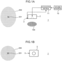
- FIG. 1A is a top view illustrating an example of the configuration of the acoustic system 1 according to the first embodiment.
- FIG. 1B is a front view illustrating an example of the configuration of the acoustic system 1 according to the first embodiment.
- the acoustic system 1 includes a speaker 2, a microphone 3, a sound source 10, and an acoustic device 11.
- an audio signal indicating music, voice, and/or the like output from the sound source 10 such as a CD player is subjected to signal processing by the acoustic device 11 and then played back by the speaker 2.
- the playback sound played back by the speaker 2 is detected by the microphone 3 installed in the vicinity of the speaker 2.
- a detection sound signal indicating the detection sound detected by the microphone 3 is input to the acoustic device 11.
- the acoustic system 1 causes the playback sound played back by the speaker 2 to be listened to in the playback area 100 set in front of the speaker 2 at a location in proximity to the speaker 2.
- the acoustic system 1 prevents the playback sound from being perceived in the non-playback area 200 located outside the playback area 100. Therefore, the acoustic device 11 adjusts the level of the audio signal output from the sound source 10 using the detection sound signal detected by the microphone 3.
- the playback sound leaks to the non-playback area 200, it is difficult to set the level of the playback sound to "0" in the non-playback area 200.
- the level of the playback sound leaking to the non-playback area 200 (hereinafter, leakage sound) is lower than the level of the ambient sound around the non-playback area 200 (hereinafter, background noise), the leakage sound is lost in the background noise and cannot be listened to.
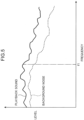
- general background noise has a characteristic that the level decreases as the frequency increases. For example, not only noise of vehicles such as a train, an aircraft, and an automobile, but also noise in a factory, noise in an office, and the like have this characteristic.
- the acoustic device 11 performs signal processing of reducing the level of frequency components equal to or greater than the frequency f1 in an audio signal. Due to this, at the representative point 201, the level of the playback sound no longer exceeds the level of the background noise, and the playback sound is no longer perceived by the person present at the representative point 201.
- FIGS. 4 and 5 are views illustrating examples of frequency characteristics of the playback sound and the background noise in the playback area 100.
- the horizontal axis represents the frequency components of the playback sound and the background noise in the playback area 100
- the vertical axis represents the level of each frequency component of the playback sound and the background noise.
- the acoustic device 11 functions as a first generation unit 21, a second generation unit 22, and an adjustment unit 20 by the CPU executing a control program (program) stored in the memory.
- the first generation unit 21 includes a transfer characteristic correction unit 131 and a subtraction unit 14, and the second generation unit 22 includes a transfer characteristic correction unit 132.
- the adjustment unit 20 includes two frequency analysis units 151 and 152, a comparison unit 16, and a correction unit 12. Note that each unit of the first generation unit 21, the second generation unit 22, and the adjustment unit 20 may be configured by a dedicated hardware circuit.
- An audio signal S (playback signal) output after being adjusted to a level corresponding to a volume set by a listener in the sound source 10 is input to the adjustment unit 20.
- the correction unit 12 adjusts the audio signal S having been input to a level (e.g., 0 dB) corresponding to a predetermined initial value, and causes the speaker 2 to play back the audio signal S after adjustment.
- the microphone 3 detects sound in which the playback sound played back by the speaker 2 and background noise N around the microphone 3 are mixed, and outputs, to the subtraction unit 14, a detection sound signal indicating the detection sound having been detected.
- the audio signal S output from the sound source 10 is also input to the first generation unit 21.
- the first generation unit 21 generates a background-noise signal indicating the ambient sound around the microphone 3 based on the audio signal S having been input, a detection sound signal indicating the detection sound detected by the microphone 3, and a transfer characteristic (first characteristic) of a voice signal from the speaker 2 to the microphone 3.
- the transfer characteristic correction unit 131 performs, using a coefficient "C11", convolution processing on the audio signal S having been input, thereby generating a signal after the convolution processing as a playback sound signal indicating the playback sound listened to at the installation location of the microphone 3.
- the transfer characteristic correction unit 131 outputs, to the subtraction unit 14, the playback sound signal having been generated.
- the coefficient "C11” is a coefficient approximating a transfer characteristic of the voice signal from the speaker 2 to the microphone 3.
- the coefficient "C11” is defined in advance based on the detection sound signal indicating detection sound detected by the microphone 3, for example, in a case where the speaker 2 is caused to play back an experimental voice signal.
- the coefficient "C11” may be described as a transfer characteristic C11 from the speaker 2 to the microphone 3.
- the subtraction unit 14 generates, as a background-noise signal indicating background noise around the microphone 3, a signal in which the playback sound signal generated by the transfer characteristic correction unit 131 is subtracted from the detection sound signal indicating the detection sound detected by the microphone 3.
- the detection sound signal indicating the detection sound detected by the microphone 3 can be expressed as "C11 ⁇ S + N”
- the playback sound signal generated by the transfer characteristic correction unit 131 can be expressed as "C11 ⁇ S”.
- “S” indicates the audio signal S.
- "N” is a voice signal indicating the background noise N around the microphone 3.
- the audio signal S output from the sound source 10 is also input to the second generation unit 22. Based on the audio signal S having been input and a transfer characteristic (second characteristic) of a voice signal from the speaker 2 to the representative point 201 of the non-playback area 200, the second generation unit 22 generates a leakage sound signal indicating the playback sound listened to at the representative point 201.
- second characteristic transfer characteristic
- the transfer characteristic correction unit 132 performs, using a coefficient "C13", convolution processing on the audio signal S having been input, thereby generating a voice signal "C13 ⁇ S" after the convolution processing as a leakage sound signal indicating the playback sound listened to at the representative point 201 of the non-playback area 200.
- the coefficient "C13” is a coefficient approximating a transfer characteristic of the voice signal from the speaker 2 to the representative point 201 of the non-playback area 200.
- the coefficient "C13” is defined in advance based on the detection sound signal indicating detection sound detected by a microphone installed at the representative point 201 of the non-playback area 200, for example, in a case where the speaker 2 is caused to play back an experimental voice signal.
- the coefficient "C13” may be described as a transfer characteristic C13 from the speaker 2 to the representative point 201.
- the representative point 201 of the non-playback area 200 may be an arbitrary location outside the playback area 100, such as the location of the microphone 3 installed in proximity to the speaker 2, for example.
- the coefficient "C13" can be defined using the microphone 3 without taking time and effort to move the installation location of the microphone 3 or time and effort to install a microphone other than the microphone 3 at the representative point 201.
- the adjustment unit 20 adjusts the level of the audio signal S input from the sound source 10 so that the level of the leakage sound signal generated by the second generation unit 22 is smaller than the level of the background-noise signal generated by the first generation unit 21.
- the adjustment unit 20 causes the speaker 2 to play back the audio signal S after adjustment.
- the frequency analysis unit 151 calculates the level of each of the plurality of frequency components in the background-noise signal generated by the first generation unit 21.
- the frequency analysis unit 152 calculates the level of each of the plurality of frequency components in the leakage sound signal generated by the second generation unit 22.
- the comparison unit 16 compares the level of each frequency component of the background-noise signal calculated by the frequency analysis unit 151 with the level of each frequency component of the leakage sound signal calculated by the frequency analysis unit 152, and outputs, to the correction unit 12, as a comparison result, a magnitude relationship and a difference between the level of each frequency component of the background-noise signal and the level of each frequency component of the leakage sound signal.
- the correction unit 12 Based on the comparison result input from the comparison unit 16, the correction unit 12 adjusts the level of the audio signal S input from the sound source 10 so that the level of the leakage sound signal is smaller than the level of the background-noise signal. The correction unit 12 causes the speaker 2 to play back the audio signal S after adjustment.
- the level of the playback sound listened to at the representative point 201b in the playback area 100b indicated by the leakage sound signal smaller than the level of the ambient sound around the microphone 3b indicated by the background-noise signal, it is also possible to the playback sound played back by the speaker 2b to be avoided from being perceived by the listener "listener B" present in the playback area 100b.
- the transfer characteristic C23 may be a transfer characteristic of a voice signal from the speaker 2b to the microphone 3c.
- the coefficient "C23" used by the second generation unit 22b to generate the leakage sound signal can be defined using the microphone 3c without taking time and effort to move the installation location of the microphone 3c or time and effort to install a microphone other than the microphone 3c at the representative point 201b.
- the audio signal S1b (second playback signal) output after being adjusted to a level corresponding to the volume set by the listener "listener B" in the sound source 90b is input to the adjustment unit 20Bb.
- the correction unit 12c adjusts the audio signal S1b to a level (e.g., 0 dB) corresponding to a predetermined initial value, and causes the speaker 2c to play back the audio signal S1b after adjustment.
- the microphone 3c detects sound in which the playback sound played back by the speaker 2c and background noise N around the microphone 3c are mixed, and outputs, to the subtraction unit 14c, a detection sound signal (second detection sound signal) indicating the detection sound having been detected.
- the audio signal S1b output from the sound source 90b is also input to the first generation unit 21c.
- the first generation unit 21c generates a background-noise signal (second background-noise signal) indicating the ambient sound around the microphone 3c based on the audio signal S1b having been input, the detection sound signal indicating the detection sound detected by the microphone 3c, and a transfer characteristic (second transfer characteristic) of the voice signal from the speaker 2c to the microphone 3c.
- the transfer characteristic correction unit 131c performs, using a coefficient "C31", convolution processing on the audio signal S1b having been input, thereby generating a signal after the convolution processing as a playback sound signal indicating the playback sound listened to at the installation location of the microphone 3c.
- the transfer characteristic correction unit 131c outputs, to the subtraction unit 14c, the playback sound signal having been generated.
- the coefficient "C31” is a coefficient approximating a transfer characteristic of the voice signal from the speaker 2c to the microphone 3c.
- the coefficient "C31” is defined in advance based on the detection sound signal indicating detection sound detected by the microphone 3c, for example, in a case where the speaker 2c is caused to play back an experimental voice signal.
- the coefficient "C31” may be described as a transfer characteristic C31 from the speaker 2c to the microphone 3c.
- the subtraction unit 14c generates, as a background-noise signal indicating background noise around the microphone 3c, a signal in which the playback sound signal generated by the transfer characteristic correction unit 131c is subtracted from the detection sound signal indicating the detection sound detected by the microphone 3c.
- the detection sound signal indicating the detection sound detected by the microphone 3c can be expressed as "C31 ⁇ S1b + N”
- the playback sound signal generated by the transfer characteristic correction unit 131c can be expressed as "C31 ⁇ S1b”.
- S1b indicates the audio signal S1b.
- N is a voice signal indicating the background noise N around the microphone 3c.
- the audio signal S1b output from the sound source 90b is also input to the second generation unit 22c.
- the second generation unit 22c generates a leakage sound signal (second leakage sound signal) indicating the playback sound listened to at the representative point 201a based on the audio signal S1b having been input and a transfer characteristic (fourth transfer characteristic) of the voice signal from the speaker 2c to the representative point 201a (second representative point) located in the playback area 100a.
- the representative point 201a may be, for example, a location in the playback area 100a such as the location of the left ear of the listener "listener A" present in the playback area 100a where the playback sound played back by the speaker 2b is listened to.
- the transfer characteristic correction unit 132c performs, using a coefficient "C33", convolution processing on the audio signal S1b having been input, thereby generating a voice signal "C33 ⁇ S1b" after the convolution processing as a leakage sound signal indicating the playback sound listened to at the representative point 201a.
- the coefficient "C33” is a coefficient approximating a transfer characteristic of the voice signal from the speaker 2c to the representative point 201a.
- the coefficient "C33” is defined in advance based on the detection sound signal indicating detection sound detected by a microphone installed at the representative point 201a, for example, in a case where the speaker 2c is caused to play back an experimental voice signal.
- the coefficient "C33” may be described as a transfer characteristic C33 from the speaker 2c to the representative point 201a.
- the adjustment unit 20Bb adjusts the level of the audio signal S1b so that the level of the leakage sound signal generated by the second generation unit 22c is smaller than the level of the background-noise signal generated by the first generation unit 21c.
- the adjustment unit 20Bb causes the speaker 2c to play back the audio signal S1b after adjustment.
- the frequency analysis unit 151c performs predetermined frequency analysis processing such as fast Fourier transform (FFT), thereby calculating the level of each frequency component of the background-noise signal generated by the first generation unit 21c.
- the frequency analysis unit 152c calculates the level of each frequency component of the leakage sound signal generated by the second generation unit 22c.
- the comparison unit 16c compares the level of each frequency component of the background-noise signal calculated by the frequency analysis unit 151c with the level of each frequency component of the leakage sound signal calculated by the frequency analysis unit 152c, and outputs, to the correction unit 12c, as a comparison result, a magnitude relationship and a difference between the level of each frequency component of the background-noise signal and the level of each frequency component of the leakage sound signal.
- the correction unit 12c Based on the comparison result input from the comparison unit 16c, the correction unit 12c adjusts the level of the audio signal S1b input from the sound source 90b so that the level of the leakage sound signal is smaller than the level of the background-noise signal. The correction unit 12c causes the speaker 2c to play back the audio signal S1b after adjustment.
- the correction unit 12c attenuates the level of the frequency component corresponding to the target frequency component in the audio signal S1b by equal to or greater than a difference between the level of the target frequency component greater in level than the background-noise signal in the leakage sound signal and the level of the frequency component corresponding to the target frequency component in the background-noise signal.
- the adjustment unit 20Bb adjusts the audio signal S1b by comparing the leakage sound signal indicating not the playback sound having a great level detected by the microphone 3c but the playback sound listened to at the representative point 201a with the background-noise signal, the adjustment unit 20Bb can appropriately adjust the level of the audio signal S1b without excessively adjusting the level. This can cause the listener "listener B" listen to the playback sound played back by the speaker 2c in the playback area 100b.
- the level of the playback sound listened to at the representative point 201a in the playback area 100a indicated by the leakage sound signal smaller than the level of the ambient sound around the microphone 3c indicated by the background-noise signal, it is also possible to the playback sound played back by the speaker 2c to be avoided from being perceived by the listener "listener A" present in the playback area 100a.
- the transfer characteristic C33 may be a transfer characteristic of a voice signal from the speaker 2c to the microphone 3b.
- the coefficient "C33" used by the second generation unit 22c to generate the leakage sound signal can be defined using the microphone 3b without taking time and effort to move the installation location of the microphone 3b or time and effort to install a microphone other than the microphone 3b at the representative point 201a.
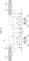
- FIG. 16 excludes the determination unit 17 ( FIG. 12 ) of each of the acoustic devices 11Ba and 11Bb from the configuration related to the two speakers 2b and 2c and the two microphones 3b and 3c.
- the acoustic device 11Ba needs not function as the determination unit 17 ( FIG. 12 ), the correction unit 12a of the acoustic device 11Ba may adjust the level of the audio signal S1a based on the comparison result input from the comparison unit 16a, and the correction unit 12b may adjust the level of the audio signal S1b at an individual adjustment degree from the correction unit 12a based on the comparison result input from the comparison unit 16b.
- the present configuration can avoid the playback sound to be listened by another listener from perceiving by the listener but there is a possibility of failing to cause the listener to feel stereo playback.
- each of the acoustic devices 11Ba and 11Bb performs the operation described in the modification of the first embodiment without excluding the determination unit 17 from each of the acoustic devices 11Ba and 11Bb.
- the determination unit 17 of the acoustic device 11Ba outputs, to the correction unit 12a and the correction unit 12b, information necessary for adjustment of the correction unit 12a and the correction unit 12b, based on the comparison results input from the comparison unit 16a and the comparison unit 16b. Due to this, the correction unit 12a and the correction unit 12b adjust the levels of the third frequency components of the audio signal S1a and the audio signal S2a by the same amount. The same applies to the acoustic device 11Bb.
- the first generation unit 21b and the second generation unit 22b of the acoustic device 11Ba may be configured similarly to the first generation unit 21A and the second generation unit 22A of the acoustic device 11A ( FIG. 10 ).
- the first generation unit 21c and the second generation unit 22c of the acoustic device 11Bc may be configured similarly to the first generation unit 21A and the second generation unit 22A of the acoustic device 11A ( FIG. 10 ). In these cases, it is possible to reduce the scale of the configuration and the calculation amount necessary for generation of the leakage sound signal.
- the acoustic system 1C of the second embodiment can also be applied to a case where the playback sound played back by the speaker installed in each of three or more seats arranged in proximity to each other, such as passenger seats of a train and an aircraft, are listened to only in a playback area set near the head of the seated person of each seat.
- two acoustic systems 1Ca and 1Cb may be configured as illustrated in FIG. 17.
- FIG. 17 is a view illustrating an example of a case where the acoustic system 1C according to the second embodiment is applied to three seats.
- the operation of the acoustic system 1Ca may be similar to the operation of the acoustic system 1C described with reference to FIG. 16 .
- the relationship between the listener "listener B” and a listener “listener C” is also the same as the relationship between the listener "listener A” and the listener “listener B” illustrated in FIG. 13 , and thus, the operation of the acoustic system 1Cb may be similar to the operation of the acoustic system 1C described with reference to FIG. 16 .
- the listener "listener B” in FIG. 17 may be considered to correspond to the listener “listener A” in FIG. 16
- the listener “listener C” in FIG. 17 may be considered to correspond to the listener “listener B” in FIG. 16
- a representative point 201c in the playback area 100b where the listener “listener B” is present in FIG. 17 may be considered to correspond to the representative point 201a of the listener “listener A” in FIG. 16
- a representative point 201d in a playback area 100c where the listener "listener C” is present may be considered to correspond to the representative point 201b in the playback area 100b where the listener "listener B” is present in FIG. 16
- the operation of the acoustic system 1Cb may be similar to the operation of the acoustic system 1C described with reference to FIG. 16 .
- the configuration of the acoustic system 1B targeting one listener illustrated in FIG. 11 may be applied to the acoustic system 1C targeting two listeners as illustrated in FIG. 13 .
- the configuration of the acoustic system 1B targeting one listener illustrated in FIG. 11 may be applied to a sound system targeting three or more listeners similarly to that applied to the sound systems 1Ca and 1Cb targeting three listeners as illustrated in FIG. 17 .
Landscapes
- Engineering & Computer Science (AREA)
- Physics & Mathematics (AREA)
- Acoustics & Sound (AREA)
- Signal Processing (AREA)
- Health & Medical Sciences (AREA)
- Otolaryngology (AREA)
- General Health & Medical Sciences (AREA)
- Mechanical Engineering (AREA)
- Soundproofing, Sound Blocking, And Sound Damping (AREA)
- Circuit For Audible Band Transducer (AREA)
Abstract
Description
- The present invention relates to a technique for performing audio playback only in the vicinity of a listener.
- In recent years, a directional speaker is used as an acoustic device that plays back music, voice, or the like only in a specific place. The directional speaker is constituted by a array speaker in which a large number of speakers are installed in a line as described in
Patent Literature 1, for example. The directional speaker adjusts, for each frequency, the level of a signal played back by each speaker so that playback sound can be listened to only in a preset playback area. - However, in reality, the playback sound leaks to a non-playback area outside the playback area, and therefore it is difficult to set the level of the playback sound to "0" in the non-playback area. Therefore,
Patent Literature 1 describes performing an adjustment of narrowing the width of the playback area when the sound pressure level of playback sound leaking to the non-playback area exceeds the surrounding noise level. It is described that this suppresses the sound pressure level of playback sound leaking to the non-playback area to be smaller than the surrounding noise level. - However, in the technique of
Patent Literature 1, the width of the playback area is adjusted to be narrow when the sound pressure level of playback sound leaking to the outside of the playback area is suppressed, and thus there is a possibility that a person present at the end of the playback area before the adjustment cannot normally listen to the playback sound. - Patent Literature 1:
JP 2017-50847 A - The present disclosure has been made to solve the above problem, and an object of the present disclosure is to provide a technique that enables playback sound to be normally listened to in a playback area and playback sound leaking to the outside of the playback area to be avoided from being perceived.
- An acoustic device according to one aspect of the present disclosure is an acoustic device that adjusts playback sound played back by a speaker so that the playback sound is listened to in a predetermined playback area, the acoustic device including: a first generation unit that generates a background-noise signal indicating ambient sound around a microphone installed in proximity to the speaker, based on a playback signal output from a sound source of the playback sound, a detection sound signal indicating detection sound detected by the microphone, and a first characteristic that is a transfer characteristic of a voice signal from the speaker to the microphone; a second generation unit that generates a leakage sound signal indicating the playback sound listened to at a representative point located outside the playback area, based on the playback signal and a second characteristic that is a transfer characteristic of a voice signal from the speaker to the representative point; and an adjustment unit that adjusts a level of the playback signal so that a level of the leakage sound signal is smaller than a level of the background-noise signal.
-
-
FIG. 1A is a top view illustrating an example of a configuration of an acoustic system according to a first embodiment. -
FIG. 1B is a front view illustrating an example of the configuration of the acoustic system according to the first embodiment. -
FIG. 2 is a view illustrating an example of frequency characteristics of playback sound and background noise in a non-playback area. -
FIG. 3 is a view illustrating an example of frequency characteristics of playback sound and background noise in the non-playback area. -
FIG. 4 is a view illustrating an example of frequency characteristics of playback sound and background noise in a playback area. -
FIG. 5 is a view illustrating an example of frequency characteristics of playback sound and background noise in the playback area. -
FIG. 6 is a view illustrating an example of a detailed configuration of the acoustic system according to the first embodiment. -
FIG. 7 is a flowchart showing an example of signal processing performed in the acoustic device. -
FIG. 8 is a view illustrating an example of a transfer characteristic from a speaker to a microphone and a transfer characteristic from the speaker to a representative point of a non-playback area. -
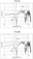
FIG. 9A is a view illustrating an example of a difference characteristic between two transfer characteristics and an approximation characteristic thereof. -
FIG. 9B is a view illustrating an example of a difference characteristic between two transfer characteristics and an approximation characteristic thereof. -
FIG. 10 is a view illustrating an example of a configuration of an acoustic system according to a modification of the first embodiment. -
FIG. 11 is a view illustrating an example of a configuration of an acoustic system according to another modification of the first embodiment. -
FIG. 12 is a view illustrating an example of a detailed configuration of an acoustic system according to another modification of the first embodiment. -
FIG. 13 is a view illustrating an example of a configuration of an acoustic system according to a second embodiment. -
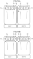
FIG. 14A is a view illustrating an example of installation locations of a plurality of speakers and a plurality of microphones included in the acoustic system according to the second embodiment. -
FIG. 14B is a view illustrating an example of installation locations of the plurality of speakers and the plurality of microphones included in the acoustic system according to the second embodiment. -
FIG. 15A is a front view illustrating another example of installation locations of the plurality of speakers and the plurality of microphones included in the acoustic system according to the second embodiment. -
FIG. 15B is a top view illustrating another example of installation locations of the plurality of speakers and the plurality of microphones included in the acoustic system according to the second embodiment. -
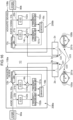
FIG. 16 is a view illustrating an example of a detailed configuration of the acoustic system according to the second embodiment. -
FIG. 17 is a view illustrating an example of a case where the acoustic system according to the second embodiment is applied to three seats. -
FIG. 18 is a view illustrating an example of a configuration of an area playback system according to a known technique. - As described above, the known directional speaker is constituted by a array speaker in which a large number of speakers are installed in a line as described in
Patent Literature 1, for example. The known directional speaker adjusts, for each frequency, the level of a signal played back by each speaker so that playback sound can be listened to only in a preset playback area. -
FIG. 18 illustrates an example of the configuration of anarea playback system 1000 according to the known technique. Specifically, as illustrated inFIG. 18 , in thearea playback system 1000, aprocessing unit 300 performs predetermined signal processing on an audio signal input from asound source 10, and outputs the audio signal after the signal processing to a array speaker 9. - In the signal processing by the
processing unit 300, the audio signal input from thesound source 10 is convolved with a control filter for implementing area playback under playback conditions designated by a user. The control filter is derived using a predetermined expression (Expression (7) in Patent Literature 1) in accordance with the playback conditions. The playback conditions include a length L of the array speaker 9, an arrangement interval Δx between each ofspeakers 2a to 2h, the number of thespeakers 2a to 2h included in the array speaker 9, a distance yref from the array speaker 9 to aplayback area 100, and a width lb of theplayback area 100. - The array speaker 9 plays back an audio signal after signal processing by the
processing unit 300. Due to this, playback sound indicated by the audio signal can be clearly listened to in theplayback area 100. However, in reality, the playback sound leaks tonon-playback areas playback area 100. Therefore, it is difficult to set the level of the playback sound to "0" in thenon-playback areas non-playback areas - On the other hand, in a case where the surrounding noise level decreases or the level of the playback sound is set to be large during playback of the playback sound, there is a possibility that leakage sound is listened to in the
non-playback areas non-playback areas - Therefore, in the technique of
Patent Literature 1, amicrophone 3 detects the surrounding noise level, and when the level of the leakage sound in thenon-playback areas playback area 100 is adjusted to be narrowed. Due to this, the level of the leakage sound is suppressed to be smaller than the level of the background noise, and even when the level of the background noise or the playback sound fluctuates, the leakage sound is not listened to in thenon-playback areas - However, in the technique of
Patent Literature 1, in the case of suppressing the playback sound leaking to thenon-playback areas playback area 100 is adjusted to be narrow. For this reason, there is a possibility that a person present at the end of theplayback area 100 before the adjustment cannot normally listen to the playback sound. - In the technique of
Patent Literature 1, it is not considered that sounds of a plurality of sound sources are individually listened to in a plurality of playback areas by using the plurality of sound sources. - For example, it is assumed that a plurality of passenger seats provided on a train, an airplane, and the like, and a plurality of adjacent seats such as a driver seat and a passenger seat of an automobile are each set as a playback area, and sounds of sound sources for the respective seats are individually played back by a array speaker installed in each of the seats. In this case, it is necessary to suppress leakage sound between a plurality of adjacent seats so that the sound played back at each seat is not perceived in the adjacent seat. During playback of playback sound, noise such as traveling sound and flight sound and playback sound at each seat can always fluctuate, and therefore suppression control of leakage sound in accordance with these fluctuations is also necessary.
- However,
Patent Literature 1 does not describe such suppression control of leakage sound. Even if the suppression technique of leakage sound ofPatent Literature 1 described above is adopted, the width of the playback area is adjusted to be narrow, and the range in which the playback sound can be normally listened to in each seat is narrowed. For this reason, there is a possibility that a seated person cannot normally listen to playback sound. - Since the array speaker 9 is configured by arranging the
N speakers 2a to 2h in a line, it is difficult to downsize the array speaker 9. For this reason, it is difficult to install the array speaker 9 in each of a plurality of adjacent seats provided in a train, an aircraft, an automobile, and the like. - Therefore, the present inventor has intensively studied a technique that enables playback sound to be normally listened to in a playback area and playback sound leaking to the outside of the playback area to be avoided from being perceived, and has arrived at each aspect of the present disclosure described below.
- (1) An acoustic device according to one aspect of the present disclosure is an acoustic device that adjusts playback sound played back by a speaker so that the playback sound is listened to in a predetermined playback area, the acoustic device including: a first generation unit that generates a background-noise signal indicating ambient sound around a microphone installed in proximity to the speaker, based on a playback signal output from a sound source of the playback sound, a detection sound signal indicating detection sound detected by the microphone, and a first characteristic that is a transfer characteristic of a voice signal from the speaker to the microphone; a second generation unit that generates a leakage sound signal indicating the playback sound listened to at a representative point located outside the playback area, based on the playback signal and a second characteristic that is a transfer characteristic of a voice signal from the speaker to the representative point; and an adjustment unit that adjusts a level of the playback signal so that a level of the leakage sound signal is smaller than a level of the background-noise signal.
- In the present configuration, the background-noise signal indicating the ambient sound around the microphone and the leakage sound signal indicating the playback sound listened to at the representative point located outside the playback area are generated, and the level of the playback signal is adjusted so that the level of the leakage sound signal is smaller than the level of the background-noise signal.
- As described above, the present configuration adjusts the level of the playback signal by comparing the level of the leakage sound signal indicating not the playback sound having a great level detected by the microphone but the playback sound listened to at the representative point located outside the playback area with the level of the background-noise signal. Therefore, the level of the playback signal can be appropriately adjusted without being excessively adjusted. Due to this, the present configuration can cause the playback sound to be normally listened to in the playback area. Moreover, the present configuration can also avoid the playback sound leaking to the outside of the playback area from being perceived, by making the level of the playback sound listened to at the representative point indicated by the leakage sound signal smaller than the level of the ambient sound around the microphone indicated by the background-noise signal.
- (2) In the acoustic device according to (1), the adjustment unit may calculate a difference level that is a difference between a level of a target frequency component, which is a frequency component greater in level than the background-noise signal in the leakage sound signal, and a level of a frequency component corresponding to the target frequency component in the background-noise signal, and attenuate, by equal to or greater than the difference level, a level of a frequency component corresponding to the target frequency component in the playback signal.
- According to the present configuration, it is possible to appropriately suppress only a frequency component greater in level than the ambient sound around the microphone in the playback sound leaking to the outside of the playback area.
- (3) In the acoustic device according to (1) or (2), the first generation unit may generate a playback sound signal indicating the playback sound listened to at an installation location of the microphone based on the playback signal and the first characteristic, and generate, as the background-noise signal, a signal in which the playback sound signal is subtracted from the detection sound signal, and the second generation unit may generate the leakage sound signal based on the playback sound signal and an approximation characteristic approximating a difference characteristic between the first characteristic and the second characteristic.
- According to the present configuration, the leakage sound signal is generated based on the playback sound signal generated by the first generation unit and the approximation characteristic approximating the difference characteristic between the first characteristic and the second characteristic. Therefore, the present configuration can reduce the scale of the configuration and the calculation amount necessary for generation of the leakage sound signal as compared with the case of generating the leakage sound signal based on the playback signal and the second characteristic.
- (4) In the acoustic device according to (3), the approximation characteristic may indicate that a level of each of a plurality of frequency components in a voice signal is constant.
- According to the present configuration, since the approximation characteristic indicates that the level of each of the plurality of frequency components in the voice signal is constant, the leakage sound signal can be easily generated only by uniformly changing, by a certain amount, the levels of all frequency components of the playback sound signal.
- (5) In the acoustic device according to (3), the approximation characteristic may indicate that a level of a frequency component lower than a predetermined reference frequency component in a voice signal is a first level that is constant, and a level of a frequency component higher than the reference frequency component in a voice signal is a second level that is constant and different from the first level.
- In the present configuration, the approximation characteristic indicates that the level of the frequency component lower than the reference frequency component in the voice signal and the level of the frequency component higher than the reference frequency component are different constant levels. Therefore, according to the present configuration, it is possible to easily generate the leakage sound signal only by uniformly changing, by a certain amount, the level of the frequency component lower than the reference frequency component in the playback sound signal and uniformly changing, by a certain amount, the level of the frequency component higher than the reference frequency component in the playback sound signal.
- (6) An acoustic device according to another aspect of the present disclosure is an acoustic device that adjusts a first playback sound played back by a first speaker and a second playback sound played back by a second speaker so that the first playback sound is listened to in a predetermined first playback area and the second playback sound is listened to in a predetermined second playback area, in which the first speaker is installed in a first seat, the second speaker is installed in a second seat in proximity to the first seat, and the acoustic device includes a first generation unit that generates a first background-noise signal indicating ambient sound around a first microphone installed in proximity to the first speaker, based on a first playback signal output from a sound source of the first playback sound, a first detection sound signal indicating a detection sound detected by the first microphone, and a first transfer characteristic that is a transfer characteristic of a voice signal from the first speaker to the first microphone, and generates a second background-noise signal indicating ambient sound around a second microphone installed in proximity to the second speaker, based on a second playback signal output from a sound source of the second playback sound, a second detection sound signal indicating a detection sound detected by the second microphone, and a second transfer characteristic that is a transfer characteristic of a voice signal from the second speaker to the second microphone, a second generation unit that generates a first leakage sound signal indicating the first playback sound listened to at a first representative point located in the second playback area, based on the first playback signal and a third transfer characteristic that is a transfer characteristic of a voice signal from the first speaker to a first representative point, and generates a second leakage sound signal indicating the second playback sound listened to at a second representative point located in the first playback area, based on the second playback signal and a fourth transfer characteristic that is a transfer characteristic of a voice signal from the second speaker to the second representative point, and an adjustment unit that adjusts a level of the first playback signal so that a level of the first leakage sound signal is smaller than a level of the first background-noise signal, and adjusts a level of the second playback signal so that a level of the second leakage sound signal is smaller than a level of the second background-noise signal.
- In the present configuration, the first background-noise signal indicating the ambient sound around the first microphone and the first leakage sound signal indicating the first playback sound listened to at the first representative point located in the second playback area are generated, and the level of the first playback signal is adjusted so that the level of the first leakage sound signal is smaller than the level of the first background-noise signal.
- As described above, the present configuration adjusts the level of the first playback signal by comparing the level of the first leakage sound signal indicating not the first playback sound having a great level detected by the first microphone but the first playback sound listened to at the representative point located in the second playback area with the level of the first background-noise signal. Therefore, the level of the first playback signal can be appropriately adjusted without being excessively adjusted. Due to this, with the present configuration, the first playback sound played back by the first speaker installed in the first seat can be normally listened to in the first playback area. Moreover, the present configuration can also avoid the first playback sound played back at the first seat from being perceived in the second playback area, by making the level of the first playback sound listened to at the representative point of the second playback area indicated by the first leakage sound signal smaller than the level of the ambient sound around the first microphone indicated by the first background-noise signal.
- Similarly to this, the present configuration can cause the second playback sound played back by the second speaker installed in the second seat to be normally listened to in the second playback area. The present configuration can also avoid the second playback sound played back at the second seat from being perceived in the first playback area.
- (7) In the acoustic device according to (6), the adjustment unit may calculate a first difference level that is a difference between a level of a first frequency component, which is a frequency component greater in level than the first background-noise signal in the first leakage sound signal, and a level of a frequency component corresponding to the first frequency component in the first background-noise signal, and attenuate, by equal to or greater than the first difference level, a level of a frequency component corresponding to the first frequency component in the first playback signal, and calculate a second difference level that is a difference between a level of a second frequency component, which is a frequency component greater in level than the second background-noise signal in the second leakage sound signal, and a level of a frequency component corresponding to the second frequency component in the second background-noise signal, and attenuate, by equal to or greater than the second difference level, a level of a frequency component corresponding to the second frequency component in the second playback signal.
- According to the present configuration, it is possible to appropriately suppress only a frequency component greater in level than the ambient sound around the first microphone in the first playback sound leaking to the second playback area. Similarly to this, it is possible to appropriately suppress, in the second playback sound leaking to the first playback area, only a frequency component greater in level than the ambient sound around the second microphone.
- (8) In the acoustic device according to (6) or (7), the first generation unit may generate a first playback sound signal indicating the first playback sound listened to at an installation location of the first microphone, based on the first playback signal and the first transfer characteristic, generate, as the first background-noise signal, a signal in which the first playback sound signal is subtracted from the first detection sound signal, generate a second playback sound signal indicating the second playback sound listened to at an installation location of the second microphone, based on the second playback signal and the second transfer characteristic, generate, as the second background-noise signal, a signal in which the second playback sound signal is subtracted from the second detection sound signal, and the second generation unit may generate the first leakage sound signal based on the first playback sound signal and a first approximation characteristic approximating a difference characteristic between the first transfer characteristic and the third transfer characteristic, and generate the second leakage sound signal based on the second playback sound signal and a second approximation characteristic approximating a difference characteristic between the second transfer characteristic and the fourth transfer characteristic.
- According to the present configuration, the first leakage sound signal is generated based on the first playback sound signal generated by the first generation unit and the first approximation characteristic approximating the difference characteristic between the first transfer characteristic and the third transfer characteristic. Therefore, the present configuration can reduce the scale of the configuration and the calculation amount necessary for generation of the first leakage sound signal as compared with the case of generating the first leakage sound signal based on the first playback signal and the third transfer characteristic. Similarly to this, according to the present configuration, it is possible to reduce the scale of the configuration and the calculation amount necessary for generation of the second leakage sound signal as compared with the case of generating the second leakage sound signal based on the second playback signal and the fourth transfer characteristic.
- (9) In the acoustic device according to (8), the first approximation characteristic and the second approximation characteristic may indicate that a level of each of a plurality of frequency components in a voice signal is constant.
- In the present configuration, the first approximation characteristic and the second approximation characteristic indicate that a level of each of a plurality of frequency components in a voice signal is constant. Therefore, according to the present configuration, it is possible to easily generate the first leakage sound signal only by uniformly changing, by a certain amount, the levels of all frequency components of the first playback sound signal. Similarly to this, according to the present configuration, it is possible to easily generate the second leakage sound signal only by uniformly changing, by a certain amount, the levels of all frequency components of the second playback sound signal.
- (10) In the acoustic device according to (8), the first approximation characteristic and the second approximation characteristic may indicate that a level of a frequency component lower than a predetermined reference frequency component in a voice signal is a first level that is constant, and a level of a frequency component higher than the reference frequency component in a voice signal is a second level that is constant and different from the first level.
- In the present configuration, the first approximation characteristic and the second approximation characteristic indicate that the level of the frequency component lower than the reference frequency component in the voice signal and the level of the frequency component higher than the reference frequency component are different constant levels. Therefore, according to the present configuration, it is possible to easily generate the first leakage sound signal only by uniformly changing, by a certain amount, the level of the frequency component lower than the reference frequency component in the first playback sound signal and uniformly changing, by a certain amount, the level of the frequency component higher than the reference frequency component in the first playback sound signal. Similarly, according to the present configuration, it is possible to easily generate the second leakage sound signal only by uniformly changing, by a certain amount, the level of the frequency component lower than the reference frequency component in the second playback sound signal and uniformly changing, by a certain amount, the level of the frequency component higher than the reference frequency component in the second playback sound signal.
- (11) In the acoustic device according to (6), the first representative point may be a location where the second microphone is installed, and the second representative point may be a location where the first microphone is installed.
- According to the present configuration, since the first representative point located in the second playback area is the location where the second microphone is installed, the third transfer characteristic, which is the transfer characteristic of the voice signal from the first speaker to the first representative point, can be derived using the second detection sound signal indicating the detection sound detected by the second microphone.
- Therefore, the present configuration can reduce the cost and effort required to derive the third transfer characteristic as compared with the case where a microphone other than the second microphone is installed in the second playback area, and the transfer characteristic of the voice signal from the first speaker to the installation location of the microphone is derived as the third transfer characteristic. Similarly, according to the present configuration, it is possible to reduce the cost and effort required to derive the fourth transfer characteristic as compared with the case where a microphone other than the first microphone is installed in the first playback area, and the transfer characteristic of the voice signal from the second speaker to the installation location of the microphone is derived as the fourth transfer characteristic.
- (12) In the acoustic device according to (1), the speaker may include a first speaker and a second speaker installed in an identical seat, the playback area may include a common playback area for listening to a first playback sound played back by the first speaker and a second playback sound played back by the second speaker, the representative point may include a first representative point and a second representative point located outside the common playback area, the microphone may include a first microphone installed in proximity to the first speaker and a second microphone installed in proximity to the second speaker, the first characteristic may include a first first characteristic that is a transfer characteristic of a voice signal from the first speaker to the first microphone, and a second first characteristic that is a transfer characteristic of a voice signal from the second speaker to the second microphone, the second characteristic may include a first second characteristic that is a transfer characteristic of a voice signal from the first speaker to the first representative point, and a second second characteristic that is a transfer characteristic of a voice signal from the second speaker to the second representative point, the first generation unit may generate a first background-noise signal indicating ambient sound around the first microphone, based on a first playback signal output from a sound source of the first playback sound, a first detection sound signal indicating a detection sound detected by the first microphone, and the first first characteristic, and may generate a second background-noise signal indicating ambient sound around the second microphone, based on a second playback signal output from a sound source of the second playback sound, a second detection sound signal indicating a detection sound detected by the second microphone, and the second first characteristic, the second generation unit may generate a first leakage sound signal indicating the first playback sound listened to at the first representative point, based on the first playback signal and the first second characteristic, and may generate a second leakage sound signal indicating the second playback sound listened to at the second representative point, based on the second playback signal and the second second characteristic, and the adjustment unit may adjust levels of the first playback signal and the second playback signal so that a level of the first leakage sound signal is smaller than a level of the first background-noise signal, and a level of the second leakage sound signal is smaller than a level of the second background-noise signal.
- In the present configuration, the first background-noise signal indicating the ambient sound around the first microphone and the first leakage sound signal indicating the first playback sound listened to at the first representative point located outside the common playback area are generated, and the second background-noise signal indicating the ambient sound around the second microphone and the second leakage sound signal indicating the second playback sound listened to at the second representative point located outside the common playback area are generated. Then, the levels of the first playback signal and the second playback signal are adjusted so that the level of the first leakage sound signal is smaller than the level of the first background-noise signal and the level of the second leakage sound signal is smaller than the level of the second background-noise signal.
- As described above, the present configuration adjusts the levels of the first playback signal and the second playback signal by comparing the level of the first leakage sound signal indicating not the first playback sound having a great level detected by the first microphone but the first playback sound listened to at the first representative point with the level of the first background-noise signal, and comparing the level of the second leakage sound signal indicating not the second playback sound having a great level detected by the second microphone but the second playback sound listened to at the second representative point with the level of the second background-noise signal. Therefore, in the present configuration, the levels of the first playback signal and the second playback signal can be appropriately adjusted without being excessively adjusted. Due to this, with the present configuration, the first playback sound and the second playback sound can be normally listened to in the common playback area for listening to the first playback sound and the second playback sound.
- Moreover, the present configuration can also avoid the first playback sound and the second playback sound from being perceived in the outside of the common playback area, by making the level of the first playback sound listened to at the first representative point indicated by the first leakage sound signal smaller than the level of the ambient sound around the first microphone indicated by the first background-noise signal, and making the level of the second playback sound listened to at the second representative point indicated by the second leakage sound signal smaller than the level of the ambient sound around the second microphone indicated by the second background-noise signal.
- (13) In the acoustic device according to (12), the adjustment unit may specify a first frequency component that is a frequency component greater in level than the first background-noise signal in the first leakage sound signal, specify a second frequency component that is a frequency component greater in level than the second background-noise signal in the second leakage sound signal, and attenuate a level of a third frequency component, which is a frequency component corresponding to the first frequency component or the second frequency component, in each of the first playback signal and the second playback signal, by equal to or greater than a larger difference between a difference between a level of the third frequency component in the first leakage sound signal and a level of the third frequency component in the first background-noise signal and a difference between a level of the third frequency component in the second leakage sound signal and a level of the third frequency component in the second background-noise signal.
- According to the present configuration, the level of the third frequency component in each of the first playback sound and the second playback sound leaking to the outside of the common playback area can be appropriately suppressed by using the larger difference between the difference between the level of the third frequency component in the first leakage sound signal and the level of the third frequency component in the first background-noise signal and the difference between the level of the third frequency component in the second leakage sound signal and the level of the third frequency component in the second background-noise signal.
- (14) A playback method according to another aspect of the present disclosure is a playback method in an acoustic device that adjusts playback sound played back by a speaker so that the playback sound is listened to in a predetermined playback area, the playback method including: generating a background-noise signal indicating ambient sound around a microphone installed in proximity to the speaker, based on a playback signal output from a sound source of the playback sound, a detection sound signal indicating detection sound detected by the microphone, and a first characteristic that is a transfer characteristic of a voice signal from the speaker to the microphone; generating a leakage sound signal indicating the playback sound listened to at a representative point located outside the playback area, based on the playback signal and a second characteristic that is a transfer characteristic of a voice signal from the speaker to the representative point; and adjusting a level of the playback signal so that a level of the leakage sound signal is smaller than a level of the background-noise signal.
- According to the present configuration, the same actions and effects as those of the acoustic device according to (1) can be obtained.
- (15) A program according to another aspect of the present disclosure is a program causing a computer of an acoustic device that adjusts playback sound played back by a speaker so that the playback sound is listened to in a predetermined playback area to execute processing, the program causing the computer to execute processing of generating a background-noise signal indicating ambient sound around a microphone installed in proximity to the speaker, based on a playback signal output from a sound source of the playback sound, a detection sound signal indicating detection sound detected by the microphone, and a first characteristic that is a transfer characteristic of a voice signal from the speaker to the microphone, generating a leakage sound signal indicating the playback sound listened to at a representative point located outside the playback area, based on the playback signal and a second characteristic that is a transfer characteristic of a voice signal from the speaker to the representative point, and adjusting a level of the playback signal so that a level of the leakage sound signal is smaller than a level of the background-noise signal.
- According to the present configuration, the same actions and effects as those of the acoustic device according to (1) can be obtained.
- (16) A playback method according to another aspect of the present disclosure is a playback method in an acoustic device that adjusts a first playback sound played back by a first speaker and a second playback sound played back by a second speaker so that the first playback sound is listened to in a predetermined first playback area and the second playback sound is listened to in a predetermined second playback area, in which the first speaker is installed in a first seat, the second speaker is installed in a second seat in proximity to the first seat, and the playback method includes generating a first background-noise signal indicating ambient sound around a first microphone installed in proximity to the first speaker, based on a first playback signal output from a sound source of the first playback sound, a first detection sound signal indicating a detection sound detected by the first microphone, and a first transfer characteristic that is a transfer characteristic of a voice signal from the first speaker to the first microphone, generating a second background-noise signal indicating ambient sound around a second microphone installed in proximity to the second speaker, based on a second playback signal output from a sound source of the second playback sound, a second detection sound signal indicating a detection sound detected by the second microphone, and a second transfer characteristic that is a transfer characteristic of a voice signal from the second speaker to the second microphone, generating a first leakage sound signal indicating the first playback sound listened to at a first representative point located in the second playback area, based on the first playback signal and a third transfer characteristic that is a transfer characteristic of a voice signal from the first speaker to the first representative point, generating a second leakage sound signal indicating the second playback sound listened to at a second representative point located in the first playback area, based on the second playback signal and a fourth transfer characteristic that is a transfer characteristic of a voice signal from the second speaker to the second representative point, adjusting a level of the first playback signal so that a level of the first leakage sound signal is smaller than a level of the first background-noise signal, and adjusting a level of the second playback signal so that a level of the second leakage sound signal is smaller than a level of the second background-noise signal.
- According to the present configuration, the same actions and effects as those of the acoustic device according to (6) can be obtained.
- (17) A program according to another aspect of the present disclosure is a program causing a computer of an acoustic device that adjusts a first playback sound played back by a first speaker and a second playback sound played back by a second speaker so that the first playback sound is listened to in a predetermined first playback area and the second playback sound is listened to in a predetermined second playback area to execute processing, in which the first speaker is installed in a first seat, the second speaker is installed in a second seat in proximity to the first seat, and the program causing the computer to execute processing of generating a first background-noise signal indicating ambient sound around a first microphone installed in proximity to the first speaker, based on a first playback signal output from a sound source of the first playback sound, a first detection sound signal indicating a detection sound detected by the first microphone, and a first transfer characteristic that is a transfer characteristic of a voice signal from the first speaker to the first microphone, generating a second background-noise signal indicating ambient sound around a second microphone installed in proximity to the second speaker, based on a second playback signal output from a sound source of the second playback sound, a second detection sound signal indicating a detection sound detected by a second microphone, and a second transfer characteristic that is a transfer characteristic of a voice signal from the second speaker to the second microphone, generating a first leakage sound signal indicating the first playback sound listened to at a first representative point located in the second playback area, based on the first playback signal and a third transfer characteristic that is a transfer characteristic of a voice signal from the first speaker to the first representative point, generating a second leakage sound signal indicating the second playback sound listened to at a second representative point located in the first playback area, based on the second playback signal and a fourth transfer characteristic that is a transfer characteristic of a voice signal from the second speaker to the second representative point, adjusting a level of the first playback signal so that a level of the first leakage sound signal is smaller than a level of the first background-noise signal, and adjusting a level of the second playback signal so that a level of the second leakage sound signal is smaller than a level of the second background-noise signal.
- According to the present configuration, the same actions and effects as those of the acoustic device according to (6) can be obtained.
- The present disclosure can also be implemented as a system that operates by such a program. It is needless to say that such a computer program can be distributed via a computer-readable non-transitory recording medium such as a CD-ROM or via a communication network such as the Internet.
- Note that each embodiment described below illustrates a specific example of the present disclosure. The constituent elements, the arrangement locations of the constituent elements, the connection forms, the order of the operations, and the like indicated in the following embodiments are merely examples, and are not intended to limit the present disclosure. A constituent element not described in an independent claim representing the highest concept among constituent elements in the embodiments below is described as an arbitrary constituent element. In all the embodiments, respective contents can be combined.
- Hereinafter, the configuration of an
acoustic system 1 according to the first embodiment will be described.FIG. 1A is a top view illustrating an example of the configuration of theacoustic system 1 according to the first embodiment.FIG. 1B is a front view illustrating an example of the configuration of theacoustic system 1 according to the first embodiment. As illustrated inFIG. 1A , theacoustic system 1 includes aspeaker 2, amicrophone 3, asound source 10, and anacoustic device 11. - In the
acoustic system 1, an audio signal indicating music, voice, and/or the like output from thesound source 10 such as a CD player is subjected to signal processing by theacoustic device 11 and then played back by thespeaker 2. The playback sound played back by thespeaker 2 is detected by themicrophone 3 installed in the vicinity of thespeaker 2. A detection sound signal indicating the detection sound detected by themicrophone 3 is input to theacoustic device 11. - The
acoustic system 1 causes the playback sound played back by thespeaker 2 to be listened to in theplayback area 100 set in front of thespeaker 2 at a location in proximity to thespeaker 2. On the other hand, theacoustic system 1 prevents the playback sound from being perceived in thenon-playback area 200 located outside theplayback area 100. Therefore, theacoustic device 11 adjusts the level of the audio signal output from thesound source 10 using the detection sound signal detected by themicrophone 3. - However, in reality, since the playback sound leaks to the
non-playback area 200, it is difficult to set the level of the playback sound to "0" in thenon-playback area 200. However, if the level of the playback sound leaking to the non-playback area 200 (hereinafter, leakage sound) is lower than the level of the ambient sound around the non-playback area 200 (hereinafter, background noise), the leakage sound is lost in the background noise and cannot be listened to. -
FIGS. 2 and3 are views illustrating examples of frequency characteristics of playback sound and background noise in thenon-playback area 200. InFIGS. 2 and3 , the horizontal axis represents the frequency components of the playback sound and the background noise in thenon-playback area 200, and the vertical axis represents the level of each frequency component of the playback sound and the background noise. For example, as illustrated inFIG. 2 , when the level of the playback sound of the frequency component of equal to or greater than a frequency f1 is larger than the level of the background noise, a person present at arepresentative point 201 representing thenon-playback area 200 perceives the playback sound of the frequency component of equal to or greater than the frequency f1. On the other hand, the playback sound of the frequency component of equal to or less than the frequency f1 is masked by the background noise, it is not perceived by the person present at therepresentative point 201 representing thenon-playback area 200. - Note that general background noise has a characteristic that the level decreases as the frequency increases. For example, not only noise of vehicles such as a train, an aircraft, and an automobile, but also noise in a factory, noise in an office, and the like have this characteristic.
- Therefore, as illustrated in
FIG. 3 , theacoustic device 11 performs signal processing of reducing the level of frequency components equal to or greater than the frequency f1 in an audio signal. Due to this, at therepresentative point 201, the level of the playback sound no longer exceeds the level of the background noise, and the playback sound is no longer perceived by the person present at therepresentative point 201. -
FIGS. 4 and5 are views illustrating examples of frequency characteristics of the playback sound and the background noise in theplayback area 100. InFIGS. 4 and5 , the horizontal axis represents the frequency components of the playback sound and the background noise in theplayback area 100, and the vertical axis represents the level of each frequency component of the playback sound and the background noise. When the signal processing is performed in theacoustic device 11, the level of the frequency components equal to or greater than the frequency f1 of the playback sound listened to by the person present in theplayback area 100 also decreases. However, since theplayback area 100 is closer to thespeaker 2 than therepresentative point 201, before the signal processing is performed, the level of the playback sound is sufficiently larger than the level of the background noise as illustrated inFIG. 4 , for example. Therefore, as illustrated inFIG. 5 , also after the signal processing is performed, the playback sound is perceived by the person present in theplayback area 100 without being lost in the background noise. - The signal processing performed in the
acoustic device 11 will be described in more detail with reference toFIG. 6. FIG. 6 is a view illustrating an example of a detailed configuration of theacoustic system 1 according to the first embodiment. As illustrated inFIG. 6 , theacoustic device 11 includes, for example, a computer including a central processing unit (CPU) such as a digital signal processor (DSP) or a micro-processing unit (MPU), i.e., microprocessor, a memory, and an integrated circuit such as a field programmable gate array (FPGA). - The
acoustic device 11 functions as afirst generation unit 21, asecond generation unit 22, and anadjustment unit 20 by the CPU executing a control program (program) stored in the memory. Thefirst generation unit 21 includes a transfercharacteristic correction unit 131 and asubtraction unit 14, and thesecond generation unit 22 includes a transfercharacteristic correction unit 132. Theadjustment unit 20 includes twofrequency analysis units comparison unit 16, and acorrection unit 12. Note that each unit of thefirst generation unit 21, thesecond generation unit 22, and theadjustment unit 20 may be configured by a dedicated hardware circuit. - An audio signal S (playback signal) output after being adjusted to a level corresponding to a volume set by a listener in the
sound source 10 is input to theadjustment unit 20. In theadjustment unit 20, thecorrection unit 12 adjusts the audio signal S having been input to a level (e.g., 0 dB) corresponding to a predetermined initial value, and causes thespeaker 2 to play back the audio signal S after adjustment. Themicrophone 3 detects sound in which the playback sound played back by thespeaker 2 and background noise N around themicrophone 3 are mixed, and outputs, to thesubtraction unit 14, a detection sound signal indicating the detection sound having been detected. - The audio signal S output from the
sound source 10 is also input to thefirst generation unit 21. Thefirst generation unit 21 generates a background-noise signal indicating the ambient sound around themicrophone 3 based on the audio signal S having been input, a detection sound signal indicating the detection sound detected by themicrophone 3, and a transfer characteristic (first characteristic) of a voice signal from thespeaker 2 to themicrophone 3. - Specifically, in the
first generation unit 21, the transfercharacteristic correction unit 131 performs, using a coefficient "C11", convolution processing on the audio signal S having been input, thereby generating a signal after the convolution processing as a playback sound signal indicating the playback sound listened to at the installation location of themicrophone 3. The transfercharacteristic correction unit 131 outputs, to thesubtraction unit 14, the playback sound signal having been generated. - Here, the coefficient "C11" is a coefficient approximating a transfer characteristic of the voice signal from the
speaker 2 to themicrophone 3. The coefficient "C11" is defined in advance based on the detection sound signal indicating detection sound detected by themicrophone 3, for example, in a case where thespeaker 2 is caused to play back an experimental voice signal. Hereinafter, the coefficient "C11" may be described as a transfer characteristic C11 from thespeaker 2 to themicrophone 3. - The
subtraction unit 14 generates, as a background-noise signal indicating background noise around themicrophone 3, a signal in which the playback sound signal generated by the transfercharacteristic correction unit 131 is subtracted from the detection sound signal indicating the detection sound detected by themicrophone 3. - Specifically, the detection sound signal indicating the detection sound detected by the
microphone 3 can be expressed as "C11 · S + N", and the playback sound signal generated by the transfercharacteristic correction unit 131 can be expressed as "C11 · S". Here, "S" indicates the audio signal S. "N" is a voice signal indicating the background noise N around themicrophone 3. Thesubtraction unit 14 generates, as a background-noise signal indicating the background noise around themicrophone 3, a voice signal "N (= C11 · S + N - C11 · S)" in which the playback sound signal "C11 · S" is subtracted from the detection sound signal "C11 · S + N". - The audio signal S output from the
sound source 10 is also input to thesecond generation unit 22. Based on the audio signal S having been input and a transfer characteristic (second characteristic) of a voice signal from thespeaker 2 to therepresentative point 201 of thenon-playback area 200, thesecond generation unit 22 generates a leakage sound signal indicating the playback sound listened to at therepresentative point 201. - Specifically, in the
second generation unit 22, the transfercharacteristic correction unit 132 performs, using a coefficient "C13", convolution processing on the audio signal S having been input, thereby generating a voice signal "C13 · S" after the convolution processing as a leakage sound signal indicating the playback sound listened to at therepresentative point 201 of thenon-playback area 200. - Here, the coefficient "C13" is a coefficient approximating a transfer characteristic of the voice signal from the
speaker 2 to therepresentative point 201 of thenon-playback area 200. The coefficient "C13" is defined in advance based on the detection sound signal indicating detection sound detected by a microphone installed at therepresentative point 201 of thenon-playback area 200, for example, in a case where thespeaker 2 is caused to play back an experimental voice signal. Hereinafter, the coefficient "C13" may be described as a transfer characteristic C13 from thespeaker 2 to therepresentative point 201. - Note that the
representative point 201 of thenon-playback area 200 may be an arbitrary location outside theplayback area 100, such as the location of themicrophone 3 installed in proximity to thespeaker 2, for example. When therepresentative point 201 is the location of themicrophone 3, the coefficient "C13" can be defined using themicrophone 3 without taking time and effort to move the installation location of themicrophone 3 or time and effort to install a microphone other than themicrophone 3 at therepresentative point 201. - The
adjustment unit 20 adjusts the level of the audio signal S input from thesound source 10 so that the level of the leakage sound signal generated by thesecond generation unit 22 is smaller than the level of the background-noise signal generated by thefirst generation unit 21. Theadjustment unit 20 causes thespeaker 2 to play back the audio signal S after adjustment. - Specifically, in the
adjustment unit 20, by performing predetermined frequency analysis processing such as fast Fourier transform (FFT), thefrequency analysis unit 151 calculates the level of each of the plurality of frequency components in the background-noise signal generated by thefirst generation unit 21. Similarly to thefrequency analysis unit 151, by performing predetermined frequency analysis processing such as fast Fourier transform (FFT), thefrequency analysis unit 152 calculates the level of each of the plurality of frequency components in the leakage sound signal generated by thesecond generation unit 22. - The
comparison unit 16 compares the level of each frequency component of the background-noise signal calculated by thefrequency analysis unit 151 with the level of each frequency component of the leakage sound signal calculated by thefrequency analysis unit 152, and outputs, to thecorrection unit 12, as a comparison result, a magnitude relationship and a difference between the level of each frequency component of the background-noise signal and the level of each frequency component of the leakage sound signal. - Based on the comparison result input from the
comparison unit 16, thecorrection unit 12 adjusts the level of the audio signal S input from thesound source 10 so that the level of the leakage sound signal is smaller than the level of the background-noise signal. Thecorrection unit 12 causes thespeaker 2 to play back the audio signal S after adjustment. - Specifically, the
correction unit 12 attenuates the level of the frequency component corresponding to a target frequency component in the audio signal S by equal to or greater than a difference between the level of the frequency component (hereinafter, the target frequency component) greater in level than the background-noise signal in the leakage sound signal and the level of the frequency component corresponding to the target frequency component in the background-noise signal. - For example, the
correction unit 12 attenuates the level of the frequency component corresponding to the target frequency component in the audio signal S by a level larger by a predetermined error level than the difference between the level of the target frequency component in the leakage sound signal and the level of the frequency component corresponding to the target frequency component in the background-noise signal. The frequency component corresponding to the target frequency component in the voice signal is a frequency component having the same frequency as the target frequency component among the plurality of frequency components included in the voice signal. - However, the present invention is not limited to this, and the
correction unit 12 may attenuate the level of the frequency component corresponding to the target frequency component in the audio signal S by the difference between the level of the target frequency component in the leakage sound signal and the level of the frequency component corresponding to the target frequency component in the background-noise signal without using the error level. - Next, the flow of the signal processing described above performed in the
acoustic device 11 will be described.FIG. 7 is a flowchart showing an example of the signal processing performed in theacoustic device 11. As shown inFIG. 7 , when output of the audio signal S adjusted to the level corresponding to the volume set by the listener in thesound source 10 is started, the audio signal S is input to thecorrection unit 12, thefirst generation unit 21, and the second generation unit 22 (step ST1). - The
correction unit 12 causes thespeaker 2 to play back the audio signal S input in step ST1. Thecorrection unit 12 causes thespeaker 2 to play back the audio signal S whose level has been adjusted in step S6 described later (step ST2). Themicrophone 3 detects sound in which the playback sound played back by thespeaker 2 and background noise around themicrophone 3 are mixed, and outputs, to thesubtraction unit 14, a detection sound signal indicating the detection sound having been detected (step ST3). - The
first generation unit 21 generates the background-noise signal indicating the ambient sound around themicrophone 3 based on the audio signal S having been input, the detection sound signal indicating the detection sound detected by themicrophone 3, and the transfer characteristic C11 of the voice signal from thespeaker 2 to the microphone 3 (step ST4). - Based on the audio signal S having been input and the transfer characteristic C13 of the voice signal from the
speaker 2 to therepresentative point 201 of thenon-playback area 200, thesecond generation unit 22 generates a leakage sound signal indicating the playback sound listened to at the representative point 201 (step ST5). - The
adjustment unit 20 adjusts the level of the audio signal S input from thesound source 10 so that the level of the leakage sound signal generated in step ST5 is smaller than the level of the background-noise signal generated in step ST4 (step ST6). - If the output of the audio signal S by the
sound source 10 has not ended (NO in step ST7), the processing in and after step ST2 is repeated. On the other hand, if the output of the audio signal S by thesound source 10 has ended (YES in step ST7), theacoustic device 11 ends the signal processing. - Next, effects obtained from the configuration of the first embodiment will be described.
FIG. 8 is a view illustrating examples of the transfer characteristic C11 from thespeaker 2 to themicrophone 3 and the transfer characteristic C13 from thespeaker 2 to therepresentative point 201 of thenon-playback area 200. - As illustrated in
FIG. 6 , the distance from thespeaker 2 to therepresentative point 201 of thenon-playback area 200 is greater than the distance from thespeaker 2 to themicrophone 3. Therefore, the level of the playback sound at therepresentative point 201 is smaller than the level of the playback sound at the installation location of themicrophone 3 due to an influence of distance attenuation. Therefore, for example, as illustrated inFIG. 8 , the level of the transfer characteristic C13 from thespeaker 2 to therepresentative point 201 is smaller than the level of the transfer characteristic C11 from thespeaker 2 to themicrophone 3. - In the configuration of the first embodiment, a background-noise signal indicating ambient sound around the
microphone 3 and a leakage sound signal indicating playback sound listened to at therepresentative point 201 of thenon-playback area 200 are generated, and the level of the audio signal S is adjusted so that the level of the leakage sound signal is smaller than the level of the background-noise signal. - As described above, the present configuration adjusts the level of the audio signal S by comparing the leakage sound signal indicating not the playback sound having a great level detected by the
microphone 3 but the playback sound listened to at therepresentative point 201 with the background-noise signal. Therefore, the level of the audio signal S can be appropriately adjusted without being excessively adjusted. Due to this, the present configuration allows the listener present in theplayback area 100 to normally listen to the playback sound. Moreover, the present configuration can also avoid the playback sound from being perceived in thenon-playback area 200, by making the level of the playback sound listened to in thenon-playback area 200 indicated by the leakage sound signal smaller than the level of the ambient sound around themicrophone 3 indicated by the background-noise signal. - The configuration of the first embodiment may be modified as follows.
FIGS. 9A and 9B are views illustrating examples of a difference characteristic C1311 and an approximation characteristic CA13 thereof of the two transfer characteristics C13 and C11. As illustrated inFIGS. 9A and 9B , by approximating the difference characteristic C1311 between the transfer characteristic C11 and the transfer characteristic C13, it is possible to derive the approximation characteristic CA13 as indicated by the one-dot chain line inFIG. 9A and the broken line inFIG. 9B . Therefore, thesecond generation unit 22 may generate the leakage sound signal using this approximation characteristic CA13. - Note that the approximation characteristic CA13 indicated by the one-dot chain line in
FIG. 9A indicates that the level of the frequency component lower than 1 KHz in the voice signal is constant at -5 dB, the level of the frequency component of equal to or greater than 1 KHz and equal to or less than 2 KHz linearly increases from -5 dB to 0 dB, and the level of the frequency component higher than 2 KHz is constant at 0 dB. That is, the approximation characteristic CA13 is the difference characteristic C1311 between the transfer characteristic C11 and the transfer characteristic C13 approximated so as to be a characteristic similar to the frequency characteristic of a low shelving filter. The approximation characteristic CA13 indicated by the broken line portion inFIG. 9B indicates that the level of each frequency component in the voice signal is constant at -2 dB. - However, the approximation characteristic CA13 is not limited to the examples illustrated in
FIGS. 9A and 9B , and may indicate that the level of a frequency component lower than a reference frequency such as 1 KHz in the voice signal is constant at -5 dB, and the level of a frequency component higher than thereference frequency 1 KHz is constant at 0 dB. -
FIG. 10 is a view illustrating an example of the configuration of anacoustic system 1A according to a modification of the first embodiment. Specifically, as illustrated inFIG. 10 , anacoustic device 11A included in theacoustic system 1A of the modification functions as afirst generation unit 21A and asecond generation unit 22A in place of thefirst generation unit 21 and the second generation unit 22 (FIG. 6 ). Thefirst generation unit 21A includes a transfercharacteristic correction unit 131A in place of the transfer characteristic correction unit 131 (FIG. 6 ). Thesecond generation unit 22A includes a transfercharacteristic correction unit 132A in place of the transfer characteristic correction unit 132 (FIG. 6 ). - In the
first generation unit 21A, the transfercharacteristic correction unit 131A outputs the generated playback sound signal to not only thesubtraction unit 14 but also thesecond generation unit 22A. In thesecond generation unit 22A, the transfercharacteristic correction unit 132A generates a leakage sound signal using the playback sound signal input from thefirst generation unit 21A and the approximation characteristic CA13 in place of the audio signal S output from thesound source 10 and the transfer characteristic C13. - That is, the transfer
characteristic correction unit 132A performs convolution processing on a playback sound signal "C11 · S" generated by the transfercharacteristic correction unit 131A using the approximation characteristic CA13 approximating the difference characteristic C1311 between the transfer characteristic C13 and the transfer characteristic C11. As a result, the transfercharacteristic correction unit 132 outputs a leakage sound signal having a characteristic close to the leakage sound signal "C13 · S" generated by the transfercharacteristic correction unit 132A ofFIG. 6 . This gives effects equivalent to the effects obtained from the configuration of theacoustic system 1 illustrated inFIG. 6 . - In a case where the transfer
characteristic correction unit 132A generates a leakage sound signal using the approximation characteristic CA13 illustrated inFIG. 9A , the leakage sound signal can be easily generated only by uniformly attenuating, by 5 dB, the level of the frequency component lower than 1 KHz in the playback sound signal and linearly attenuating the level of the frequency component of equal to or greater than 1 KHz and equal to or less than 2 KHz in the playback sound signal. In a case where the transfercharacteristic correction unit 132A generates a leakage sound signal using the approximation characteristic CA13 illustrated inFIG. 9B , the leakage sound signal can be easily generated only by uniformly attenuating, by 2 dB, the level of each frequency component in the playback sound signal. - It is assumed that the transfer
characteristic correction unit 132 generates the leakage sound signal using the approximation characteristic CA13 indicating that the level of the frequency component lower than the reference frequency in the voice signal is the first level that is constant and the level of the frequency component higher than the reference frequency is the second level different from the first level that is constant as described above. In this case, it is possible to easily generate the leakage sound signal only by uniformly attenuating, by the amount corresponding to the absolute value of the first level, the level of the frequency component lower than the reference frequency in the playback sound signal and uniformly attenuating, by the amount corresponding to the absolute value of the second level, the level of the frequency component higher than the reference frequency in the playback sound signal. - As described above, according to the
acoustic device 11A of the present modification, generation of the leakage sound signal in thesecond generation unit 22A can be easily implemented using a biquadratic filter or the like by an infinite impulse response (IIR) filter, for example. Therefore, it is possible to reduce the scale of the configuration and the calculation amount necessary for generation of the leakage sound signal as compared with theacoustic device 11 illustrated inFIG. 6 . - In the above, the
sound systems acoustic devices sound source 10 have been described. However, audio signals of a plurality of channels such as 2 channels (stereo) are normally output from thesound source 10 such as a CD player. - Therefore, an acoustic system including an acoustic device that performs signal processing on audio signals of a plurality of channels output from a
sound source 90 will be described below. Hereinafter, anacoustic system 1B including anacoustic device 11B that performs signal processing on audio signals S1 and S2 of two channels (stereo) output from thesound source 90 will be described as a representative of the acoustic system. -
FIG. 11 is a view illustrating an example of the configuration of theacoustic system 1B according to another modification of the first embodiment. As illustrated inFIG. 11 , in theacoustic system 1B, among the audio signals S1 and S2 of two channels output from thesound source 90, the audio signal S1 (first playback signal) is subjected to signal processing by theacoustic device 11B, and then played back by aspeaker 2a (first speaker). The audio signal S2 (second playback signal) is subjected to signal processing by theacoustic device 11B, and then played back by aspeaker 2b (second speaker). - The playback sound (first playback sound) played back by the
speaker 2a is mainly detected by amicrophone 3a (first microphone) installed in proximity to thespeaker 2a. The playback sound (second playback sound) played back by thespeaker 2b is mainly detected by amicrophone 3b (second microphone) installed in proximity to thespeaker 2b. A detection sound signal (first detection sound signal) indicating the detection sound detected by themicrophone 3a and a detection sound signal (second detection sound signal) indicating the detection sound detected by themicrophone 3b are input to theacoustic device 11B. - In the
acoustic system 1B, two playback sounds played back by therespective speakers speakers speakers non-playback areas playback area 100, the two playback sounds are prevented from being perceived. Therefore, theacoustic device 11B adjusts the levels of the audio signals S1 and S2 of two channels output from thesound source 90, using the detection sound signals detected by themicrophones - Here, it is assumed that frequency characteristics of the playback sound and the background noise at a
representative point 201a (first representative point) in thenon-playback area 200a and arepresentative point 201b (second representative point) in thenon-playback area 200b are as illustrated inFIG. 2 . In this case, persons present at therepresentative point 201a and therepresentative point 201b perceive the playback sounds of the frequency components equal to or greater than the frequency f1 because they are greater in level than the background noise. On the other hand, the playback sounds having frequency components equal to or less than the frequency f1 are not perceived because they are smaller in level than the background noise, and are masked by the background noise. - Therefore, as illustrated in
FIG. 3 , similarly to theacoustic devices acoustic device 11B performs signal processing of reducing the levels of frequency components equal to or greater than the frequency f1 in the two audio signals S1 and S2. Due to this, at therepresentative point 201a and therepresentative point 201b, the levels of the playback sound played back by thespeakers representative point 201a and therepresentative point 201b. - When the signal processing is performed in the
acoustic device 11B, the level of the frequency component equal to or greater than the frequency f1 of the playback sound listened to by the person present in theplayback area 100 also decreases. However, since theplayback area 100 is closer to thespeaker 2a than therepresentative point 201a and is closer to thespeaker 2b than therepresentative point 201b, before the signal processing is performed, for example, as illustrated inFIG. 4 , the level of the playback sound is sufficiently greater than the level of the background noise. Therefore, as illustrated inFIG. 5 , also after the signal processing is performed, the playback sound in theplayback area 100 is perceived by a person present in theplayback area 100 without being lost in the background noise. - The signal processing described above performed in the
acoustic device 11B will be described in more detail with reference toFIG. 12. FIG. 12 is a view illustrating an example of a detailed configuration of theacoustic system 1B according to another modification of the first embodiment. - As illustrated in
FIG. 12 , in theacoustic system 1B, theacoustic device 11B functions as twofirst generation units second generation units adjustment unit 20B. Thefirst generation unit 21a includes a transfercharacteristic correction unit 131a and asubtraction unit 14a, and thefirst generation unit 21b includes a transfercharacteristic correction unit 131b and a subtraction unit 14b. Thesecond generation unit 22a includes a transfercharacteristic correction unit 132a, and thesecond generation unit 22b includes a transfercharacteristic correction unit 132b. Theadjustment unit 20B includes twocorrection units frequency analysis units comparison units determination unit 17. - The audio signals S1 and S2 of two channels output after being adjusted to levels corresponding to the volume set by the listener in the
sound source 90 are input to theadjustment unit 20B. In theadjustment unit 20B, thecorrection unit 12a adjusts the audio signal S1, which is one of the audio signals S1 and S2 of two channels having been input, to a level (e.g., 0 dB) in accordance with a predetermined initial value similarly to the correction unit 12 (FIG. 6 ), and causes thespeaker 2a to play back the audio signal S1 after adjustment. Themicrophone 3a detects sound in which the playback sound played back by thespeaker 2a and background noise N around themicrophone 3a are mixed, and outputs, to thesubtraction unit 14a, a detection sound signal indicating the detection sound having been detected. - The audio signal S1 is also input to the
first generation unit 21a. Similarly to the first generation unit 21 (FIG. 6 ), thefirst generation unit 21a generates a background-noise signal (first background-noise signal) indicating the ambient sound around themicrophone 3a based on the audio signal S1 having been input, the detection sound signal indicating the detection sound detected by themicrophone 3a, and the transfer characteristic C11 (first first characteristic) of the voice signal from thespeaker 2a to themicrophone 3a. Thefirst generation unit 21a outputs the generated background-noise signal to thefrequency analysis unit 151a. - Specifically, in the
first generation unit 21a, similarly to the transfer characteristic correction unit 131 (FIG. 6 ), the transfercharacteristic correction unit 131a generates, as the playback sound signal indicating the playback sound listened to at the installation location of themicrophone 3a, the signal after performing the convolution processing on the audio signal S1 using the coefficient "C11" approximating the transfer characteristic C11. Thesubtraction unit 14a generates, as a background-noise signal indicating background noise around themicrophone 3a, a signal in which the playback sound signal generated by the transfercharacteristic correction unit 131a is subtracted from the detection sound signal indicating the detection sound detected by themicrophone 3a. - The audio signal S1 is also input to the
second generation unit 22a. Similarly to the second generation unit 22 (FIG. 6 ), thesecond generation unit 22a generates a leakage sound signal (first leakage sound signal) indicating the playback sound listened to at therepresentative point 201a based on the audio signal S1 having been input and the transfer characteristic C13 (first second characteristic) of the voice signal from thespeaker 2a to therepresentative point 201a. Thesecond generation unit 22a outputs the generated leakage sound signal to thefrequency analysis unit 152a. - Specifically, in the
second generation unit 22a, similarly to the transfer characteristic correction unit 132 (FIG. 6 ), the transfercharacteristic correction unit 132a generates, as a leakage sound signal indicating the playback sound listened to at therepresentative point 201a, a signal after performing the convolution processing on the audio signal S1 using the coefficient "C13" approximating the transfer characteristic C13. - On the other hand, the audio signal S2, which is one of the audio signals S1 and S2 of two channels having been input, is input to the
correction unit 12b, thefirst generation unit 21b, and thesecond generation unit 22b. - Similarly to the
correction unit 12a, thecorrection unit 12b adjusts the audio signal S2 to a level (e.g., 0 dB) in accordance with a predetermined initial value, and causes thespeaker 2b to play back the audio signal S2 after adjustment. Themicrophone 3b detects sound in which the playback sound played back by thespeaker 2b and background noise N around themicrophone 3b are mixed, and outputs, to the subtraction unit 14b, a detection sound signal indicating the detection sound having been detected. - Similarly to the
first generation unit 21a, thefirst generation unit 21b generates a background-noise signal (second background-noise signal) indicating the ambient sound around themicrophone 3b based on the audio signal S2 having been input, the detection sound signal indicating the detection sound detected by themicrophone 3b, and a transfer characteristic C21 (second first characteristic) of the voice signal from thespeaker 2b to themicrophone 3b. Thefirst generation unit 21b outputs the generated background-noise signal to thefrequency analysis unit 151b. - Specifically, in the
first generation unit 21b, similarly to the transfercharacteristic correction unit 131a, the transfercharacteristic correction unit 131b generates, as the playback sound signal indicating the playback sound listened to at the installation location of themicrophone 3b, the signal after performing the convolution processing on the audio signal S2 using the coefficient "C21" approximating the transfer characteristic C21. The subtraction unit 14b generates, as a background-noise signal indicating background noise around themicrophone 3b, a signal in which the playback sound signal generated by the transfercharacteristic correction unit 131b is subtracted from the detection sound signal indicating the detection sound detected by themicrophone 3b. - Similarly to the
second generation unit 22a, thesecond generation unit 22b generates a leakage sound signal (second leakage sound signal) indicating the playback sound listened to at therepresentative point 201b based on the audio signal S2 having been input and a transfer characteristic C23 (second second characteristic) of the voice signal from thespeaker 2b to therepresentative point 201b. Thesecond generation unit 22b outputs the generated leakage sound signal to thefrequency analysis unit 152b. - Specifically, in the
second generation unit 22b, similarly to the transfercharacteristic correction unit 132a, the transfercharacteristic correction unit 132b generates, as a leakage sound signal indicating the playback sound listened to at therepresentative point 201b, a signal after performing the convolution processing on the audio signal S2 using the coefficient "C23" approximating the transfer characteristic C23. - The
adjustment unit 20B adjusts the levels of the two audio signals S1 and S2 so that the level of the leakage sound signal generated by thesecond generation unit 22a is smaller than the level of the background-noise signal generated by thefirst generation unit 21a and the level of the leakage sound signal generated by thesecond generation unit 22b is smaller than the level of the background-noise signal generated by thefirst generation unit 21b. Theadjustment unit 20B causes thespeaker 2a to play back the audio signal S1 after adjustment, and causes thespeaker 2b to play back the audio signal S2 after adjustment. - Specifically, in the
adjustment unit 20B, similarly to the frequency analysis unit 151 (FIG. 6 ), thefrequency analysis unit 151a calculates the level of each frequency component of the background-noise signal generated by thefirst generation unit 21a. Similarly to the frequency analysis unit 152 (FIG. 6 ), thefrequency analysis unit 152a calculates the level of each frequency component of the leakage sound signal generated by thesecond generation unit 22a. - The
comparison unit 16a compares the level of each frequency component of the background-noise signal calculated by thefrequency analysis unit 151a with the level of each frequency component of the leakage sound signal calculated by thefrequency analysis unit 152a, and outputs, to thedetermination unit 17, as a comparison result, a magnitude relationship and a difference between the level of each frequency component of the background-noise signal and the level of each frequency component of the leakage sound signal. - Similarly to the
frequency analysis unit 151a, thefrequency analysis unit 151b calculates the level of each frequency component of the background-noise signal generated by thefirst generation unit 21b. Similarly to thefrequency analysis unit 152a, thefrequency analysis unit 152b calculates the level of each frequency component of the leakage sound signal generated by thesecond generation unit 22b. - The
comparison unit 16b compares the level of each frequency component of the background-noise signal calculated by thefrequency analysis unit 151b with the level of each frequency component of the leakage sound signal calculated by thefrequency analysis unit 152b. Thecomparison unit 16b outputs, to thedetermination unit 17, as a comparison result, the magnitude relationship and the difference between the level of each frequency component of the background-noise signal and the level of each frequency component of the leakage sound signal. - With reference to the comparison result input from the
comparison unit 16a, thedetermination unit 17 specifies a frequency component (hereinafter, first frequency component) greater in level than the background-noise signal (hereinafter, first background-noise signal) generated by thefirst generation unit 21a in the leakage sound signal (hereinafter, first leakage sound signal) generated by thesecond generation unit 22a. - Similarly to this, with reference to the comparison result input from the
comparison unit 16b, thedetermination unit 17 specifies a frequency component (hereinafter, second frequency component) greater in level than the background-noise signal (hereinafter, second background-noise signal) generated by thefirst generation unit 21b in the leakage sound signal (hereinafter, second leakage sound signal) generated by thesecond generation unit 22b. - The
determination unit 17 outputs, to thecorrection unit 12a and thecorrection unit 12b, information indicating the first frequency component and the second frequency component having been specified, the difference between the level of the first frequency component in the first background-noise signal input from thecomparison unit 16a and the level of the first frequency component in the first leakage sound signal, and the difference between the level of the second frequency component in the second background-noise signal input from thecomparison unit 16b and the level of the second frequency component in the second leakage sound signal. - With reference to the information input from the
determination unit 17, thecorrection unit 12a attenuates the level of the frequency component (hereinafter, third frequency component) corresponding to the first frequency component or the second frequency component in the audio signal S1 by equal to or greater than a larger difference between the difference between the level of the third frequency component in the first leakage sound signal and the level of the third frequency component in the first background-noise signal and the difference between the level of the third frequency component in the second leakage sound signal and the level of the third frequency component in the second background-noise signal. - Similarly to the
correction unit 12a, with reference to the information input from thedetermination unit 17, thecorrection unit 12b attenuates the level of the third frequency component in the audio signal S2 by equal to or greater than a larger difference between the difference between the level of the third frequency component in the first leakage sound signal and the level of the third frequency component in the first background-noise signal and the difference between the level of the third frequency component in the second leakage sound signal and the level of the third frequency component in the second background-noise signal. Note that thecorrection unit 12b attenuates the level of the third frequency component in the audio signal S2 by the same amount as the amount by which thecorrection unit 12a attenuates the level of the third frequency component in the audio signal S1. - For example, it is assumed that the first frequency component is a frequency component of the frequency "f1", and the difference between the level of the frequency component of the frequency "f1" in the first leakage sound signal and the level of the frequency component of the frequency "f1" in the first background-noise signal is a level "L11". On the other hand, it is assumed that the difference between the level of the frequency component of the frequency "f1" in the second leakage sound signal and the level of the frequency component of the frequency "f1" in the second background-noise signal is a level "L12" smaller than the level "L11".
- It is assumed that the second frequency component is a frequency component of a frequency "f2", and the difference between the level of the frequency component of the frequency "f2" in the first leakage sound signal and the level of the frequency component of the frequency "f2" in the first background-noise signal is a level "L21". On the other hand, it is assumed that the difference between the level of the frequency component of the frequency "f2" in the second leakage sound signal and the level of the frequency component of the frequency "f2" in the second background-noise signal is a level "L22" larger than the level "L21".
- In this case, the
correction unit 12a sets the frequency component of the frequency "f1" in the audio signal S1 as the third frequency component, and attenuates the level of the frequency component of the frequency "f1" in the audio signal S1 by a level larger by a predetermined error level than the level "L111". On the other hand, thecorrection unit 12a sets the frequency component of the frequency "f2" in the audio signal S1 as the third frequency component, and attenuates the level of the frequency component of the frequency "f2" in the audio signal S1 by a level larger by the error level than the level "L22". - Similarly, the
correction unit 12b sets the frequency component of the frequency "f1" in the audio signal S2 as the third frequency component, and attenuates the level of the frequency component of the frequency "f1" in the audio signal S2 by a level larger by the error level than the level "L11". Thecorrection unit 12b sets the frequency component of the frequency "f2" in the audio signal S2 as the third frequency component, and attenuates the level of the frequency component of the frequency "f2" in the audio signal S2 by a level larger by the error level than the level "L22". - Alternatively, the
correction unit 12a may attenuate the level of the frequency component of the frequency "f1" in the audio signal S1 by the level "L11" and attenuate the level of the frequency component of the frequency f2 by the level "L22" without using the error level. In line with this, thecorrection unit 12b may attenuate the level of the frequency component of the frequency "f1" in the audio signal S2 by the level "L11" and attenuate the level of the frequency component of the frequency f2 by the level "L22" without using the error level. - Hereinafter, effects obtained by the configuration of the present modification will be described. Similarly to the acoustic device 11 (
FIG. 6 ), it is assumed that the comparison result by thecomparison unit 16a is input to thecorrection unit 12a and the comparison result by thecomparison unit 16b is input to thecorrection unit 12b. Then, it is assumed that thecorrection unit 12a adjusts the level of the audio signal S1 based on the comparison result input from thecomparison unit 16a, and thecorrection unit 12b adjusts the level of the audio signal S2 based on the comparison result input from thecomparison unit 16b. In this case, if the adjustment degree of the level of the audio signal S1 and the adjustment degree of the level of the audio signal S2 are different, there is a possibility that the listener cannot feel stereo playback of the two audio signals S1 and S2. - However, in the configuration of the present modification, based on the same information input from the
determination unit 17, both thecorrection unit 12a and thecorrection unit 12b perform adjustment of attenuating the levels of the third frequency components in the two audio signals S1 and S2 by the same amount and equal to or greater than a larger difference between the difference between the level of the third frequency component in the first leakage sound signal and the level of the third frequency component in the first background-noise signal and the difference between the level of the third frequency component in the second leakage sound signal and the level of the third frequency component in the second background-noise signal. Therefore, the level of the playback sound is smaller than the level of the background noise in both thenon-playback areas correction unit 12a is the same as the adjustment degree of the audio signal S2 in thecorrection unit 12b, the listener can feel stereo playback of the two audio signals S1 and S2 in theplayback area 100. - Similarly to the acoustic device 11 (
FIG. 6 ), the adjustment amounts of the levels of the audio signals S1 and S2 by thecorrection unit 12a and thecorrection unit 12b are calculated based on the levels of the leakage sound signals indicating the playback sounds listened to at the representative points of thenon-playback areas playback area 100 without excessively attenuating the levels. - Note that the
first generation unit 21a and thesecond generation unit 22a of theacoustic device 11B (FIG. 12 ) may be configured similarly to thefirst generation unit 21A and thesecond generation unit 22A of theacoustic device 11A (FIG. 10 ). Similarly, thefirst generation unit 21b and thesecond generation unit 22b of theacoustic device 11B (FIG. 12 ) may be configured similarly to thefirst generation unit 21A and thesecond generation unit 22A of theacoustic device 11A (FIG. 10 ). In these cases, it is possible to reduce the scale of the configuration and the calculation amount necessary for generation of the leakage sound signal. - Next, an
acoustic system 1C according to the second embodiment will be described.FIG. 13 is a view illustrating an example of the configuration of theacoustic system 1C according to the second embodiment. As illustrated inFIG. 13 , theacoustic system 1C according to the second embodiment corresponds to a configuration in which two of theacoustic systems 1B (FIG. 11 ) described in the modification of the first embodiment are arranged in proximity to each other, and includes fourspeakers 2a to 2d, fourmicrophones 3a to 3d, two acoustic devices 11Ba and 11Bb, and twosound sources - The
acoustic system 1C according to the second embodiment is adopted, for example, in a case where the playback sound played back by a speaker installed in each of two seats in proximity to each other such as two adjacent seats as in a train, an airplane, and the like and a driver seat and a passenger seat of an automobile is listened to only in theplayback area 100 set near the head of a seated person of each seat. -
FIGS. 14A and 14B are views illustrating examples of installation locations of the fourspeakers 2a to 2d and the fourmicrophones 3a to 3d included in theacoustic system 1C.FIG. 14A illustrates an example of installing the fourspeakers 2a to 2d in headrest portions of two seats in proximity to each other in which the seat back is integrated up to the headrest portion, which are adopted in seats of a train or the like.FIG. 14B illustrates an example of installing the fourspeakers 2a to 2d in headrest portions of two seats in proximity to each other in which the seat back is and the headrest portion are separated, which are adopted in a driver seat, a passenger seat, and the like of an automobile. As illustrated inFIGS. 14A and 14B , the fourmicrophones 3a to 3d are installed on the side surface sides of thespeakers 2a to 2d, respectively. -
FIG. 15A is a front view illustrating another example of installation locations of the fourspeakers 2a to 2d and the fourmicrophones 3a to 3d included in theacoustic system 1C, andFIG. 15B is a top view illustrating the other example. As illustrated inFIG. 15A , in a seat "seat 1" (first seat), the twospeakers seat 2" (second seat), the twospeakers FIG. 15B , the fourspeakers 2a to 2d are attached so as to protrude from the headrest portion, and the diaphragms of the fourspeakers 2a to 2d face the ears of the seated person. As illustrated inFIGS. 15A and 15B , the fourmicrophones 3a to 3d are installed on the back side of thespeakers 2a to 2d, respectively. - Note that the installation locations of the four
microphones 3a to 3d are not limited to the above installation locations, and may be locations in proximity to thespeakers 2a to 2d, such as locations immediately beside the diaphragm in the front baffle of each of thespeakers 2a to 2d. - The two seats in proximity to each other as described above are not limited to the seats of vehicles, and may be seats in movie theaters, seats in attractions in theme parks, and seats in offices. That is, it is sufficient that the plurality of seats where the speakers are installed in the headrest portions are arranged in proximity to each other.
- As illustrated in
FIG. 13 , in theacoustic system 1C, audio signals S1a and S2a of two channels output from thesound source 90a are subjected to signal processing by the acoustic device 11Ba, and then played back by thespeakers sound source 90b are subjected to signal processing by the acoustic device 11Bb, and then played back by thespeakers - The playback sound played back by the
speaker 2a is mainly detected by themicrophone 3a, and the playback sound (first playback sound) played back by thespeaker 2b (first speaker) is mainly detected by themicrophone 3b (first microphone). The playback sound (second playback sound) played back by thespeaker 2c (second speaker) is mainly detected by themicrophone 3c (second microphone), and the playback sound played back by thespeaker 2d is mainly detected by themicrophone 3d. - The detection sound signal indicating the detection sound detected by the
microphones microphones - In the
acoustic system 1C, two playback sounds played back by therespective speakers playback area 100a (first playback area) set in front of the twospeakers seat 1" (FIG. 14A and FIG. 14B orFIG. 15A and FIG. 15B ) at locations in proximity to the twospeakers respective speakers playback area 100b (second playback area) set in front of the twospeakers seat 2" (FIG. 14A and FIG. 14B orFIG. 15A and FIG. 15B ) in proximity to the seat "seat 1" at locations in proximity to the twospeakers - However, it is problematic that the playback sound played back by the
speakers playback area 100a, the listener being a seated person on the seat "seat 1". It is problematic that the playback sound played back by thespeakers playback area 100b, the listener being a seated person on the seat "seat 2". That is, for each listener, the playback sound listened to by the seated person on the adjacent seat is an obstacle to the playback sound that the listener is listening to. Therefore, in theacoustic system 1C, the playback sounds leaking from theother playback areas playback areas - Therefore, in the
acoustic system 1C, themicrophones speakers playback area 100a. The acoustic device 11Ba adjusts the levels of the audio signals S1a and S2a of two channels output from thesound source 90a, using the detection sound signals indicating the detection sounds detected by themicrophones microphones speakers playback area 100b. The acoustic device 11Bb adjusts the levels of the audio signals S1b and S2b of two channels output from thesound source 90b, using the detection sound signals indicating the detection sounds detected by themicrophones - The signal processing performed in the acoustic devices 11Ba and 11Bb will be described in more detail with reference to
FIG. 16. FIG. 16 is a view illustrating an example of a detailed configuration of theacoustic system 1C according to another modification of the second embodiment. -
FIG. 16 extracts only the configuration related to twospeakers FIG. 13 . These are constituent elements closest to the listener "listener A" and the listener "listener B" in theacoustic system 1C, and the two playback sounds played back by the two speakers have a larger influence on each listener than that in the configuration related to the other twospeakers speakers microphones speakers microphones - As illustrated in
FIG. 16 , the configuration related to the twospeakers FIG. 6 ) of the first embodiment are independently arranged. - The
first generation unit 21b (the transfercharacteristic correction unit 131b and the subtraction unit 14b), thesecond generation unit 22b (the transfercharacteristic correction unit 132b), and an adjustment unit 20Ba (thefrequency analysis unit 151b, thefrequency analysis unit 152b, thecomparison unit 16b, and thecorrection unit 12b) of the acoustic device 11Ba related to thespeaker 2b operate similarly to the first generation unit 21 (the transfercharacteristic correction unit 131 and the subtraction unit 14), the second generation unit 22 (the transfer characteristic correction unit 132), and the adjustment unit 20 (thefrequency analysis unit 151, thefrequency analysis unit 152, thecomparison unit 16, and the correction unit 12), respectively, of the acoustic device 11 (FIG. 6 ). - A
first generation unit 21c (a transfercharacteristic correction unit 131c and asubtraction unit 14c), asecond generation unit 22c (a transfercharacteristic correction unit 132c), and an adjustment unit 20Bb (afrequency analysis unit 151c, afrequency analysis unit 152c, acomparison unit 16c, and acorrection unit 12c) of the acoustic device 11Bb related to thespeaker 2c also operate similarly to the first generation unit 21 (the transfercharacteristic correction unit 131 and the subtraction unit 14), the second generation unit 22 (the transfer characteristic correction unit 132), and the adjustment unit 20 (thefrequency analysis unit 151, thefrequency analysis unit 152, thecomparison unit 16, and the correction unit 12), respectively, of the acoustic device 11 (FIG. 6 ). - Note that the acoustic device 11Ba and the acoustic device 11Bb may be configured by an identical computer, or the acoustic device 11Ba and the acoustic device 11Bb may be configured by individual computers.
- Specifically, the audio signal S2a (first playback signal) output after being adjusted to a level corresponding to the volume set by the listener "listener A" in the
sound source 90a is input to the adjustment unit 20Ba. In the adjustment unit 20Ba, thecorrection unit 12b adjusts the audio signal S2a to a level (e.g., 0 dB) corresponding to a predetermined initial value, and causes thespeaker 2b to play back the audio signal S2a after adjustment. Themicrophone 3b detects sound in which the playback sound played back by thespeaker 2b and background noise N around themicrophone 3b are mixed, and outputs, to the subtraction unit 14b, a detection sound signal (first detection sound signal) indicating the detection sound having been detected. - The audio signal S2a output from the
sound source 90a is also input to thefirst generation unit 21b. Thefirst generation unit 21b generates a background-noise signal (first background-noise signal) indicating the ambient sound around themicrophone 3b based on the audio signal S2a having been input, a detection sound signal indicating the detection sound detected by themicrophone 3b, and a transfer characteristic (first transfer characteristic) of the voice signal from thespeaker 2b to themicrophone 3b. - Specifically, in the
first generation unit 21b, the transfercharacteristic correction unit 131b performs, using a coefficient "C21", convolution processing on the audio signal S2a having been input, thereby generating a signal after the convolution processing as a playback sound signal indicating the playback sound listened to at the installation location of themicrophone 3b. The transfercharacteristic correction unit 131b outputs, to the subtraction unit 14b, the playback sound signal having been generated. - Here, the coefficient "C21" is a coefficient approximating a transfer characteristic of the voice signal from the
speaker 2b to themicrophone 3b. The coefficient "C21" is defined in advance based on the detection sound signal indicating detection sound detected by themicrophone 3b, for example, in a case where thespeaker 2b is caused to play back an experimental voice signal. Hereinafter, the coefficient "C21" may be described as a transfer characteristic C21 from thespeaker 2b to themicrophone 3b. - The subtraction unit 14b generates, as a background-noise signal indicating background noise around the
microphone 3b, a signal in which the playback sound signal generated by the transfercharacteristic correction unit 131b is subtracted from the detection sound signal indicating the detection sound detected by themicrophone 3b. - Specifically, the detection sound signal indicating the detection sound detected by the
microphone 3b can be expressed as "C21 · S2a + N", and the playback sound signal generated by the transfercharacteristic correction unit 131b can be expressed as "C21 · S2a". Here, "S2a" indicates the audio signal S2a. "N" is a voice signal indicating the background noise N around themicrophone 3b. The subtraction unit 14b generates, as a background-noise signal indicating background noise around themicrophone 3b, a voice signal "N (= C21 · S2a + N - C21 · S)" in which the playback sound signal "C21 · S2a" is subtracted from the detection sound signal "C21 · S2a + N". - The audio signal S2a output from the
sound source 90a is also input to thesecond generation unit 22b. Thesecond generation unit 22b generates the leakage sound signal (first leakage sound signal) indicating the playback sound listened to at therepresentative point 201b based on the audio signal S2a having been input and the transfer characteristic (third transfer characteristic) of the voice signal from thespeaker 2b to therepresentative point 201b (first representative point) located in theplayback area 100b. Therepresentative point 201b may be, for example, a location in theplayback area 100b such as the location of the right ear of the listener "listener B" present in theplayback area 100b where the playback sound played back by thespeaker 2c is listened to. - Specifically, in the
second generation unit 22b, the transfercharacteristic correction unit 132b performs, using a coefficient "C23", convolution processing on the audio signal S2a having been input, thereby generating a voice signal "C23 · S2a" after the convolution processing as a leakage sound signal indicating the playback sound listened to at therepresentative point 201b. - Here, the coefficient "C23" is a coefficient approximating a transfer characteristic of the voice signal from the
speaker 2b to therepresentative point 201b. The coefficient "C23" is defined in advance based on the detection sound signal indicating detection sound detected by a microphone installed at therepresentative point 201b, for example, in a case where thespeaker 2b is caused to play back an experimental voice signal. Hereinafter, the coefficient "C23" may be described as a transfer characteristic C23 from thespeaker 2 to therepresentative point 201b. - The adjustment unit 20Ba adjusts the level of the audio signal S2a so that the level of the leakage sound signal generated by the
second generation unit 22b is smaller than the level of the background-noise signal generated by thefirst generation unit 21b. The adjustment unit 20Ba causes thespeaker 2b to play back the audio signal S2a after adjustment. - Specifically, in the adjustment unit 20Ba, the
frequency analysis unit 151b performs predetermined frequency analysis processing such as fast Fourier transform (FFT), thereby calculating the level of each frequency component of the background-noise signal generated by thefirst generation unit 21b. Similarly to thefrequency analysis unit 151b, thefrequency analysis unit 152b calculates the level of each frequency component of the leakage sound signal generated by thesecond generation unit 22b. - The
comparison unit 16b compares the level of each frequency component of the background-noise signal calculated by thefrequency analysis unit 151b with the level of each frequency component of the leakage sound signal calculated by thefrequency analysis unit 152b, and outputs, to thecorrection unit 12b, as a comparison result, a magnitude relationship and a difference between the level of each frequency component of the background-noise signal and the level of each frequency component of the leakage sound signal. - Based on the comparison result input from the
comparison unit 16b, thecorrection unit 12b adjusts the level of the audio signal S2a input from thesound source 90a so that the level of the leakage sound signal is smaller than the level of the background-noise signal. Thecorrection unit 12b causes thespeaker 2b to play back the audio signal S2a after adjustment. - Specifically, similarly to the
correction unit 12 of the first embodiment, thecorrection unit 12b attenuates the level of the frequency component corresponding to the target frequency component in the audio signal S2a by equal to or greater than a difference between the level of the target frequency component greater in level than the background-noise signal in the leakage sound signal and the level of the frequency component corresponding to the target frequency component in the background-noise signal. - That is, since the adjustment unit 20Ba adjusts the audio signal S2a by comparing the leakage sound signal indicating not the playback sound having a great level detected by the
microphone 3b but the playback sound listened to at therepresentative point 201b with the background-noise signal, the adjustment unit 20Ba can appropriately adjust the level of the audio signal S2a without excessively adjusting the level. This can cause the listener "listener A" listen to the playback sound played back by thespeaker 2b in theplayback area 100a. Moreover, by making the level of the playback sound listened to at therepresentative point 201b in theplayback area 100b indicated by the leakage sound signal smaller than the level of the ambient sound around themicrophone 3b indicated by the background-noise signal, it is also possible to the playback sound played back by thespeaker 2b to be avoided from being perceived by the listener "listener B" present in theplayback area 100b. - Note that in a case where the
microphone 3c is installed in proximity to thespeaker 2c and therepresentative point 201b, the transfer characteristic C23 may be a transfer characteristic of a voice signal from thespeaker 2b to themicrophone 3c. In this case, the coefficient "C23" used by thesecond generation unit 22b to generate the leakage sound signal can be defined using themicrophone 3c without taking time and effort to move the installation location of themicrophone 3c or time and effort to install a microphone other than themicrophone 3c at therepresentative point 201b. - Similarly, the audio signal S1b (second playback signal) output after being adjusted to a level corresponding to the volume set by the listener "listener B" in the
sound source 90b is input to the adjustment unit 20Bb. In the adjustment unit 20Bb, thecorrection unit 12c adjusts the audio signal S1b to a level (e.g., 0 dB) corresponding to a predetermined initial value, and causes thespeaker 2c to play back the audio signal S1b after adjustment. Themicrophone 3c detects sound in which the playback sound played back by thespeaker 2c and background noise N around themicrophone 3c are mixed, and outputs, to thesubtraction unit 14c, a detection sound signal (second detection sound signal) indicating the detection sound having been detected. - The audio signal S1b output from the
sound source 90b is also input to thefirst generation unit 21c. Thefirst generation unit 21c generates a background-noise signal (second background-noise signal) indicating the ambient sound around themicrophone 3c based on the audio signal S1b having been input, the detection sound signal indicating the detection sound detected by themicrophone 3c, and a transfer characteristic (second transfer characteristic) of the voice signal from thespeaker 2c to themicrophone 3c. - Specifically, in the
first generation unit 21c, the transfercharacteristic correction unit 131c performs, using a coefficient "C31", convolution processing on the audio signal S1b having been input, thereby generating a signal after the convolution processing as a playback sound signal indicating the playback sound listened to at the installation location of themicrophone 3c. The transfercharacteristic correction unit 131c outputs, to thesubtraction unit 14c, the playback sound signal having been generated. - Here, the coefficient "C31" is a coefficient approximating a transfer characteristic of the voice signal from the
speaker 2c to themicrophone 3c. The coefficient "C31" is defined in advance based on the detection sound signal indicating detection sound detected by themicrophone 3c, for example, in a case where thespeaker 2c is caused to play back an experimental voice signal. Hereinafter, the coefficient "C31" may be described as a transfer characteristic C31 from thespeaker 2c to themicrophone 3c. - The
subtraction unit 14c generates, as a background-noise signal indicating background noise around themicrophone 3c, a signal in which the playback sound signal generated by the transfercharacteristic correction unit 131c is subtracted from the detection sound signal indicating the detection sound detected by themicrophone 3c. - Specifically, the detection sound signal indicating the detection sound detected by the
microphone 3c can be expressed as "C31 · S1b + N", and the playback sound signal generated by the transfercharacteristic correction unit 131c can be expressed as "C31 · S1b". Here, "S1b" indicates the audio signal S1b. "N" is a voice signal indicating the background noise N around themicrophone 3c. Thesubtraction unit 14c generates, as a background-noise signal indicating background noise around themicrophone 3c, a voice signal "N (= C31 · S1b + N - C31 · S1b)" in which the playback sound signal "C31 · S1b" is subtracted from the detection sound signal "C31 · S1b + N". - The audio signal S1b output from the
sound source 90b is also input to thesecond generation unit 22c. Thesecond generation unit 22c generates a leakage sound signal (second leakage sound signal) indicating the playback sound listened to at therepresentative point 201a based on the audio signal S1b having been input and a transfer characteristic (fourth transfer characteristic) of the voice signal from thespeaker 2c to therepresentative point 201a (second representative point) located in theplayback area 100a. Therepresentative point 201a may be, for example, a location in theplayback area 100a such as the location of the left ear of the listener "listener A" present in theplayback area 100a where the playback sound played back by thespeaker 2b is listened to. - Specifically, in the
second generation unit 22c, the transfercharacteristic correction unit 132c performs, using a coefficient "C33", convolution processing on the audio signal S1b having been input, thereby generating a voice signal "C33 · S1b" after the convolution processing as a leakage sound signal indicating the playback sound listened to at therepresentative point 201a. - Here, the coefficient "C33" is a coefficient approximating a transfer characteristic of the voice signal from the
speaker 2c to therepresentative point 201a. The coefficient "C33" is defined in advance based on the detection sound signal indicating detection sound detected by a microphone installed at therepresentative point 201a, for example, in a case where thespeaker 2c is caused to play back an experimental voice signal. Hereinafter, the coefficient "C33" may be described as a transfer characteristic C33 from thespeaker 2c to therepresentative point 201a. - The adjustment unit 20Bb adjusts the level of the audio signal S1b so that the level of the leakage sound signal generated by the
second generation unit 22c is smaller than the level of the background-noise signal generated by thefirst generation unit 21c. The adjustment unit 20Bb causes thespeaker 2c to play back the audio signal S1b after adjustment. - Specifically, in the adjustment unit 20Bb, the
frequency analysis unit 151c performs predetermined frequency analysis processing such as fast Fourier transform (FFT), thereby calculating the level of each frequency component of the background-noise signal generated by thefirst generation unit 21c. Similarly to thefrequency analysis unit 151c, thefrequency analysis unit 152c calculates the level of each frequency component of the leakage sound signal generated by thesecond generation unit 22c. - The
comparison unit 16c compares the level of each frequency component of the background-noise signal calculated by thefrequency analysis unit 151c with the level of each frequency component of the leakage sound signal calculated by thefrequency analysis unit 152c, and outputs, to thecorrection unit 12c, as a comparison result, a magnitude relationship and a difference between the level of each frequency component of the background-noise signal and the level of each frequency component of the leakage sound signal. - Based on the comparison result input from the
comparison unit 16c, thecorrection unit 12c adjusts the level of the audio signal S1b input from thesound source 90b so that the level of the leakage sound signal is smaller than the level of the background-noise signal. Thecorrection unit 12c causes thespeaker 2c to play back the audio signal S1b after adjustment. - Specifically, similarly to the
correction unit 12 of the first embodiment, thecorrection unit 12c attenuates the level of the frequency component corresponding to the target frequency component in the audio signal S1b by equal to or greater than a difference between the level of the target frequency component greater in level than the background-noise signal in the leakage sound signal and the level of the frequency component corresponding to the target frequency component in the background-noise signal. - That is, since the adjustment unit 20Bb adjusts the audio signal S1b by comparing the leakage sound signal indicating not the playback sound having a great level detected by the
microphone 3c but the playback sound listened to at therepresentative point 201a with the background-noise signal, the adjustment unit 20Bb can appropriately adjust the level of the audio signal S1b without excessively adjusting the level. This can cause the listener "listener B" listen to the playback sound played back by thespeaker 2c in theplayback area 100b. Moreover, by making the level of the playback sound listened to at therepresentative point 201a in theplayback area 100a indicated by the leakage sound signal smaller than the level of the ambient sound around themicrophone 3c indicated by the background-noise signal, it is also possible to the playback sound played back by thespeaker 2c to be avoided from being perceived by the listener "listener A" present in theplayback area 100a. - Note that in a case where the
microphone 3b is installed in proximity to thespeaker 2b and therepresentative point 201a, the transfer characteristic C33 may be a transfer characteristic of a voice signal from thespeaker 2c to themicrophone 3b. In this case, the coefficient "C33" used by thesecond generation unit 22c to generate the leakage sound signal can be defined using themicrophone 3b without taking time and effort to move the installation location of themicrophone 3b or time and effort to install a microphone other than themicrophone 3b at therepresentative point 201a. - The flow of the signal processing described above performed in each of the acoustic device 11Ba and the acoustic device 11Bb is similar to that shown in
FIG. 7 , and thus detailed description will be omitted. - Note that the description of the second embodiment describes at the beginning that the
acoustic system 1C corresponds to the configuration in which two of theacoustic systems 1B (FIG. 11 ) described in the modification of the first embodiment are arranged in proximity to each other. However,FIG. 16 excludes the determination unit 17 (FIG. 12 ) of each of the acoustic devices 11Ba and 11Bb from the configuration related to the twospeakers microphones - Therefore, in reality, the acoustic device 11Ba needs not function as the determination unit 17 (
FIG. 12 ), thecorrection unit 12a of the acoustic device 11Ba may adjust the level of the audio signal S1a based on the comparison result input from thecomparison unit 16a, and thecorrection unit 12b may adjust the level of the audio signal S1b at an individual adjustment degree from thecorrection unit 12a based on the comparison result input from thecomparison unit 16b. The same applies to the acoustic device 11Bb. However, the present configuration can avoid the playback sound to be listened by another listener from perceiving by the listener but there is a possibility of failing to cause the listener to feel stereo playback. - Therefore, it is preferable that each of the acoustic devices 11Ba and 11Bb performs the operation described in the modification of the first embodiment without excluding the
determination unit 17 from each of the acoustic devices 11Ba and 11Bb. In this case, thedetermination unit 17 of the acoustic device 11Ba outputs, to thecorrection unit 12a and thecorrection unit 12b, information necessary for adjustment of thecorrection unit 12a and thecorrection unit 12b, based on the comparison results input from thecomparison unit 16a and thecomparison unit 16b. Due to this, thecorrection unit 12a and thecorrection unit 12b adjust the levels of the third frequency components of the audio signal S1a and the audio signal S2a by the same amount. The same applies to the acoustic device 11Bb. - The
first generation unit 21b and thesecond generation unit 22b of the acoustic device 11Ba may be configured similarly to thefirst generation unit 21A and thesecond generation unit 22A of theacoustic device 11A (FIG. 10 ). Similarly, thefirst generation unit 21c and thesecond generation unit 22c of the acoustic device 11Bc may be configured similarly to thefirst generation unit 21A and thesecond generation unit 22A of theacoustic device 11A (FIG. 10 ). In these cases, it is possible to reduce the scale of the configuration and the calculation amount necessary for generation of the leakage sound signal. - The
acoustic system 1C of the second embodiment can also be applied to a case where the playback sound played back by the speaker installed in each of three or more seats arranged in proximity to each other, such as passenger seats of a train and an aircraft, are listened to only in a playback area set near the head of the seated person of each seat. For example, in a case where the playback sound played back by the speaker installed in each of three seats in proximity to each other are listened to only in a playback area set near the head of the seated person on each seat, two acoustic systems 1Ca and 1Cb may be configured as illustrated inFIG. 17. FIG. 17 is a view illustrating an example of a case where theacoustic system 1C according to the second embodiment is applied to three seats. - Since the relationship between the listener "listener A" and the listener "listener B" illustrated in
FIG. 17 is the same as the relationship between the listener "listener A" and the listener "listener B" illustrated inFIG. 13 , the operation of the acoustic system 1Ca may be similar to the operation of theacoustic system 1C described with reference toFIG. 16 . - The relationship between the listener "listener B" and a listener "listener C" is also the same as the relationship between the listener "listener A" and the listener "listener B" illustrated in
FIG. 13 , and thus, the operation of the acoustic system 1Cb may be similar to the operation of theacoustic system 1C described with reference toFIG. 16 . - That is, the listener "listener B" in
FIG. 17 may be considered to correspond to the listener "listener A" inFIG. 16 , and the listener "listener C" inFIG. 17 may be considered to correspond to the listener "listener B" inFIG. 16 . Arepresentative point 201c in theplayback area 100b where the listener "listener B" is present inFIG. 17 may be considered to correspond to therepresentative point 201a of the listener "listener A" inFIG. 16 . Arepresentative point 201d in aplayback area 100c where the listener "listener C" is present may be considered to correspond to therepresentative point 201b in theplayback area 100b where the listener "listener B" is present inFIG. 16 . Then, the operation of the acoustic system 1Cb may be similar to the operation of theacoustic system 1C described with reference toFIG. 16 . - As described above, the configuration of the
acoustic system 1B targeting one listener illustrated inFIG. 11 may be applied to theacoustic system 1C targeting two listeners as illustrated inFIG. 13 . The configuration of theacoustic system 1B targeting one listener illustrated inFIG. 11 may be applied to a sound system targeting three or more listeners similarly to that applied to the sound systems 1Ca and 1Cb targeting three listeners as illustrated inFIG. 17 . - The technique according to the present disclosure enables playback sound to be normally listened to in a playback area and playback sound leaking to the outside of the playback area to be avoided from being perceived without using a array speaker. Therefore, the technique according to the present disclosure is useful in allowing only a seated person of each seat to listen to playback sound played back by a speaker installed in each seat in a plurality of seats in proximity to each other such as passenger seats of a train and an aircraft.
Claims (17)
- An acoustic device that adjusts playback sound played back by a speaker so that the playback sound is listened to in a predetermined playback area, the acoustic device comprising:a first generation unit that generates a background-noise signal indicating ambient sound around a microphone installed in proximity to the speaker, based on a playback signal output from a sound source of the playback sound, a detection sound signal indicating detection sound detected by the microphone, and a first characteristic that is a transfer characteristic of a voice signal from the speaker to the microphone;a second generation unit that generates a leakage sound signal indicating the playback sound listened to at a representative point located outside the playback area, based on the playback signal and a second characteristic that is a transfer characteristic of a voice signal from the speaker to the representative point; andan adjustment unit that adjusts a level of the playback signal so that a level of the leakage sound signal is smaller than a level of the background-noise signal.
- The acoustic device according to claim 1, whereinthe adjustment unitcalculates a difference level that is a difference between a level of a target frequency component, which is a frequency component greater in level than the background-noise signal in the leakage sound signal, and a level of a frequency component corresponding to the target frequency component in the background-noise signal, and attenuates, by equal to or greater than the difference level, a level of a frequency component corresponding to the target frequency component in the playback signal.
- The acoustic device according to claim 1 or 2, whereinthe first generation unitgenerates a playback sound signal indicating the playback sound listened to at an installation location of the microphone based on the playback signal and the first characteristic, andgenerates, as the background-noise signal, a signal in which the playback sound signal is subtracted from the detection sound signal, andthe second generation unitgenerates the leakage sound signal based on the playback sound signal and an approximation characteristic approximating a difference characteristic between the first characteristic and the second characteristic.
- The acoustic device according to claim 3, wherein
the approximation characteristic indicates that a level of each of a plurality of frequency components in a voice signal is constant. - The acoustic device according to claim 3, wherein
the approximation characteristic indicates that a level of a frequency component lower than a predetermined reference frequency component in a voice signal is a first level that is constant, and a level of a frequency component higher than the reference frequency component in a voice signal is a second level that is constant and different from the first level. - An acoustic device that adjusts a first playback sound played back by a first speaker and a second playback sound played back by a second speaker so that the first playback sound is listened to in a predetermined first playback area and the second playback sound is listened to in a predetermined second playback area, whereinthe first speaker is installed in a first seat,the second speaker is installed in a second seat in proximity to the first seat, andthe acoustic device includesa first generation unit that generates a first background-noise signal indicating ambient sound around a first microphone installed in proximity to the first speaker, based on a first playback signal output from a sound source of the first playback sound, a first detection sound signal indicating a detection sound detected by the first microphone, and a first transfer characteristic that is a transfer characteristic of a voice signal from the first speaker to the first microphone, andgenerates a second background-noise signal indicating ambient sound around a second microphone installed in proximity to the second speaker, based on a second playback signal output from a sound source of the second playback sound, a second detection sound signal indicating a detection sound detected by the second microphone, and a second transfer characteristic that is a transfer characteristic of a voice signal from the second speaker to the second microphone,a second generation unit that generates a first leakage sound signal indicating the first playback sound listened to at a first representative point located in the second playback area, based on the first playback signal and a third transfer characteristic that is a transfer characteristic of a voice signal from the first speaker to the first representative point, andgenerates a second leakage sound signal indicating the second playback sound listened to at a second representative point located in the first playback area, based on the second playback signal and a fourth transfer characteristic that is a transfer characteristic of a voice signal from the second speaker to the second representative point, andan adjustment unit that adjusts a level of the first playback signal so that a level of the first leakage sound signal is smaller than a level of the first background-noise signal, andadjusts a level of the second playback signal so that a level of the second leakage sound signal is smaller than a level of the second background-noise signal.
- The acoustic device according to claim 6, whereinthe adjustment unitcalculates a first difference level that is a difference between a level of a first frequency component, which is a frequency component greater in level than the first background-noise signal in the first leakage sound signal, and a level of a frequency component corresponding to the first frequency component in the first background-noise signal, and attenuates, by equal to or greater than the first difference level, a level of a frequency component corresponding to the first frequency component in the first playback signal, andcalculates a second difference level that is a difference between a level of a second frequency component, which is a frequency component greater in level than the second background-noise signal in the second leakage sound signal, and a level of a frequency component corresponding to the second frequency component in the second background-noise signal, and attenuates, by equal to or greater than the second difference level, a level of a frequency component corresponding to the second frequency component in the second playback signal.
- The acoustic device according to claim 6 or 7, whereinthe first generation unitgenerates a first playback sound signal indicating the first playback sound listened to at an installation location of the first microphone, based on the first playback signal and the first transfer characteristic,generates, as the first background-noise signal, a signal in which the first playback sound signal is subtracted from the first detection sound signal,generates a second playback sound signal indicating the second playback sound listened to at an installation location of the second microphone, based on the second playback signal and the second transfer characteristic,generates, as the second background-noise signal, a signal in which the second playback sound signal is subtracted from the second detection sound signal, andthe second generation unitgenerates the first leakage sound signal based on the first playback sound signal and a first approximation characteristic approximating a difference characteristic between the first transfer characteristic and the third transfer characteristic, andgenerates the second leakage sound signal based on the second playback sound signal and a second approximation characteristic approximating a difference characteristic between the second transfer characteristic and the fourth transfer characteristic.
- The acoustic device according to claim 8, wherein
the first approximation characteristic and the second approximation characteristic indicate that a level of each of a plurality of frequency components in a voice signal is constant. - The acoustic device according to claim 8, wherein
the first approximation characteristic and the second approximation characteristic indicate that a level of a frequency component lower than a predetermined reference frequency component in a voice signal is a first level that is constant, and a level of a frequency component higher than the reference frequency component in a voice signal is a second level that is constant and different from the first level. - The acoustic device according to claim 6, whereinthe first representative point is a location where the second microphone is installed, andthe second representative point is a location where the first microphone is installed.
- The acoustic device according to claim 1, whereinthe speaker includes a first speaker and a second speaker installed in an identical seat,the playback area includes a common playback area for listening to a first playback sound played back by the first speaker and a second playback sound played back by the second speaker,the representative point includes a first representative point and a second representative point located outside the common playback area,the microphone includes a first microphone installed in proximity to the first speaker and a second microphone installed in proximity to the second speaker,the first characteristic includes a first first characteristic that is a transfer characteristic of a voice signal from the first speaker to the first microphone, and a second first characteristic that is a transfer characteristic of a voice signal from the second speaker to the second microphone,the second characteristic includes a first second characteristic that is a transfer characteristic of a voice signal from the first speaker to the first representative point, and a second second characteristic that is a transfer characteristic of a voice signal from the second speaker to the second representative point,the first generation unitgenerates a first background-noise signal indicating ambient sound around the first microphone, based on a first playback signal output from a sound source of the first playback sound, a first detection sound signal indicating a detection sound detected by the first microphone, and the first first characteristic, andgenerates a second background-noise signal indicating ambient sound around the second microphone, based on a second playback signal output from a sound source of the second playback sound, a second detection sound signal indicating a detection sound detected by the second microphone, and the second first characteristic,the second generation unitgenerates a first leakage sound signal indicating the first playback sound listened to at the first representative point, based on the first playback signal and the first second characteristic, andgenerates a second leakage sound signal indicating the second playback sound listened to at the second representative point, based on the second playback signal and the second second characteristic, andthe adjustment unitadjusts levels of the first playback signal and the second playback signalso that a level of the first leakage sound signal is smaller than a level of the first background-noise signal, and a level of the second leakage sound signal is smaller than a level of the second background-noise signal.
- The acoustic device according to claim 12, whereinthe adjustment unitspecifies a first frequency component that is a frequency component greater in level than the first background-noise signal in the first leakage sound signal,specifies a second frequency component that is a frequency component greater in level than the second background-noise signal in the second leakage sound signal, andattenuates a level of a third frequency component, which is a frequency component corresponding to the first frequency component or the second frequency component, in each of the first playback signal and the second playback signal, by equal to or greater than a larger difference between a difference between a level of the third frequency component in the first leakage sound signal and a level of the third frequency component in the first background-noise signal and a difference between a level of the third frequency component in the second leakage sound signal and a level of the third frequency component in the second background-noise signal.
- A playback method in an acoustic device that adjusts playback sound played back by a speaker so that the playback sound is listened to in a predetermined playback area, the playback method comprising:generating a background-noise signal indicating ambient sound around a microphone installed in proximity to the speaker, based on a playback signal output from a sound source of the playback sound, a detection sound signal indicating detection sound detected by the microphone, and a first characteristic that is a transfer characteristic of a voice signal from the speaker to the microphone;generating a leakage sound signal indicating the playback sound listened to at a representative point located outside the playback area, based on the playback signal and a second characteristic that is a transfer characteristic of a voice signal from the speaker to the representative point; andadjusting a level of the playback signal so that a level of the leakage sound signal is smaller than a level of the background-noise signal.
- A program causing a computer of an acoustic device that adjusts playback sound played back by a speaker so that the playback sound is listened to in a predetermined playback area to execute processing, the program causing the computer to execute processing ofgenerating a background-noise signal indicating ambient sound around a microphone installed in proximity to the speaker, based on a playback signal output from a sound source of the playback sound, a detection sound signal indicating detection sound detected by the microphone, and a first characteristic that is a transfer characteristic of a voice signal from the speaker to the microphone,generating a leakage sound signal indicating the playback sound listened to at a representative point located outside the playback area, based on the playback signal and a second characteristic that is a transfer characteristic of a voice signal from the speaker to the representative point, andadjusting a level of the playback signal so that a level of the leakage sound signal is smaller than a level of the background-noise signal.
- A playback method in an acoustic device that adjusts a first playback sound played back by a first speaker and a second playback sound played back by a second speaker so that the first playback sound is listened to in a predetermined first playback area and the second playback sound is listened to in a predetermined second playback area, whereinthe first speaker is installed in a first seat,the second speaker is installed in a second seat in proximity to the first seat, andthe playback method includesgenerating a first background-noise signal indicating ambient sound around a first microphone installed in proximity to the first speaker, based on a first playback signal output from a sound source of the first playback sound, a first detection sound signal indicating a detection sound detected by the first microphone, and a first transfer characteristic that is a transfer characteristic of a voice signal from the first speaker to the first microphone,generating a.second background-noise signal indicating ambient sound around a second microphone installed in proximity to the second speaker, based on a second playback signal output from a sound source of the second playback sound, a second detection sound signal indicating a detection sound detected by the second microphone, and a second transfer characteristic that is a transfer characteristic of a voice signal from the second speaker to the second microphone,generating a first leakage sound signal indicating the first playback sound listened to at a first representative point located in the second playback area, based on the first playback signal and a third transfer characteristic that is a transfer characteristic of a voice signal from the first speaker to the first representative point,generating a second leakage sound signal indicating the second playback sound listened to at a second representative point located in the first playback area, based on the second playback signal and a fourth transfer characteristic that is a transfer characteristic of a voice signal from the second speaker to the second representative point,adjusting a level of the first playback signal so that a level of the first leakage sound signal is smaller than a level of the first background-noise signal, andadjusting a level of the second playback signal so that a level of the second leakage sound signal is smaller than a level of the second background-noise signal.
- A program causing a computer of an acoustic device that adjusts a first playback sound played back by a first speaker and a second playback sound played back by a second speaker so that the first playback sound is listened to in a predetermined first playback area and the second playback sound is listened to in a predetermined second playback area to execute processing, whereinthe first speaker is installed in a first seat,the second speaker is installed in a second seat in proximity to the first seat, andthe program causing the computer to execute processing ofgenerating a first background-noise signal indicating ambient sound around a first microphone installed in proximity to the first speaker, based on a first playback signal output from a sound source of the first playback sound, a first detection sound signal indicating a detection sound detected by the first microphone, and a first transfer characteristic that is a transfer characteristic of a voice signal from the first speaker to the first microphone,generating a second background-noise signal indicating ambient sound around a second microphone installed in proximity to the second speaker, based on a second playback signal output from a sound source of the second playback sound, a second detection sound signal indicating a detection sound detected by the second microphone, and a second transfer characteristic that is a transfer characteristic of a voice signal from the second speaker to the second microphone,generating a first leakage sound signal indicating the first playback sound listened to at a first representative point located in the second playback area, based on the first playback signal and a third transfer characteristic that is a transfer characteristic of a voice signal from the first speaker to the first representative point,generating a second leakage sound signal indicating the second playback sound listened to at a second representative point located in the first playback area, based on the second playback signal and a fourth transfer characteristic that is a transfer characteristic of a voice signal from the second speaker to the second representative point,adjusting a level of the first playback signal so that a level of the first leakage sound signal is smaller than a level of the first background-noise signal, andadjusting a level of the second playback signal so that a level of the second leakage sound signal is smaller than a level of the second background-noise signal.
Applications Claiming Priority (2)
| Application Number | Priority Date | Filing Date | Title |
|---|---|---|---|
| JP2022152471 | 2022-09-26 | ||
| PCT/JP2023/027068 WO2024070165A1 (en) | 2022-09-26 | 2023-07-24 | Acoustic device, playback method, and program |
Publications (2)
| Publication Number | Publication Date |
|---|---|
| EP4578739A1 true EP4578739A1 (en) | 2025-07-02 |
| EP4578739A4 EP4578739A4 (en) | 2025-11-05 |
Family
ID=90477059
Family Applications (1)
| Application Number | Title | Priority Date | Filing Date |
|---|---|---|---|
| EP23871408.3A Pending EP4578739A4 (en) | 2022-09-26 | 2023-07-24 | ACOUSTIC DEVICE, PLAYBACK METHOD AND PROGRAM |
Country Status (5)
| Country | Link |
|---|---|
| US (1) | US20250227412A1 (en) |
| EP (1) | EP4578739A4 (en) |
| JP (1) | JPWO2024070165A1 (en) |
| CN (1) | CN119923869A (en) |
| WO (1) | WO2024070165A1 (en) |
Family Cites Families (8)
| Publication number | Priority date | Publication date | Assignee | Title |
|---|---|---|---|---|
| US8306235B2 (en) * | 2007-07-17 | 2012-11-06 | Apple Inc. | Method and apparatus for using a sound sensor to adjust the audio output for a device |
| JP4640461B2 (en) * | 2008-07-08 | 2011-03-02 | ソニー株式会社 | Volume control device and program |
| JP2011211266A (en) * | 2010-03-29 | 2011-10-20 | Hitachi Omron Terminal Solutions Corp | Speaker array device |
| JP6718748B2 (en) | 2015-08-31 | 2020-07-08 | パナソニック インテレクチュアル プロパティ コーポレーション オブ アメリカPanasonic Intellectual Property Corporation of America | Area reproduction system and area reproduction method |
| JP6887139B2 (en) * | 2017-03-29 | 2021-06-16 | パナソニックIpマネジメント株式会社 | Sound processing equipment, sound processing methods, and programs |
| US11295718B2 (en) * | 2018-11-02 | 2022-04-05 | Bose Corporation | Ambient volume control in open audio device |
| WO2021010006A1 (en) * | 2019-07-17 | 2021-01-21 | パナソニックIpマネジメント株式会社 | Sound control device, sound control system, and sound control method |
| US11843927B2 (en) * | 2022-02-28 | 2023-12-12 | Panasonic Intellectual Property Management Co., Ltd. | Acoustic control system |
-
2023
- 2023-07-24 JP JP2024549784A patent/JPWO2024070165A1/ja active Pending
- 2023-07-24 CN CN202380068563.1A patent/CN119923869A/en active Pending
- 2023-07-24 EP EP23871408.3A patent/EP4578739A4/en active Pending
- 2023-07-24 WO PCT/JP2023/027068 patent/WO2024070165A1/en not_active Ceased
-
2025
- 2025-03-24 US US19/088,024 patent/US20250227412A1/en active Pending
Also Published As
| Publication number | Publication date |
|---|---|
| CN119923869A (en) | 2025-05-02 |
| US20250227412A1 (en) | 2025-07-10 |
| JPWO2024070165A1 (en) | 2024-04-04 |
| WO2024070165A1 (en) | 2024-04-04 |
| EP4578739A4 (en) | 2025-11-05 |
Similar Documents
| Publication | Publication Date | Title |
|---|---|---|
| EP3040984B1 (en) | Sound zone arrangment with zonewise speech suppresion | |
| JP6870078B2 (en) | Noise estimation for dynamic sound adjustment | |
| US10629195B2 (en) | Isolation and enhancement of short duration speech prompts in an automotive system | |
| US10848897B2 (en) | Acoustic processing device, acoustic processing method, and recording medium | |
| EP2850611A1 (en) | Noise dependent signal processing for in-car communication systems with multiple acoustic zones | |
| EP3392619B1 (en) | Audible prompts in a vehicle navigation system | |
| US10339951B2 (en) | Audio signal processing in a vehicle | |
| WO2013187946A2 (en) | Wind noise detection for in-car communication systems with multiple acoustic zones | |
| CN105304089A (en) | Fictitious shield method | |
| US10560782B2 (en) | Signal processor | |
| EP3833046A1 (en) | Sound collecting/amplifying device, method therefor, and program | |
| EP4578739A1 (en) | Acoustic device, playback method, and program | |
| US8009834B2 (en) | Sound reproduction apparatus and method of enhancing low frequency component | |
| US10614789B2 (en) | Apparatus and method for privacy enhancement | |
| US20250203309A1 (en) | Sound system | |
| US11122366B2 (en) | Method and apparatus for attenuation of audio howling | |
| JP2019198110A (en) | Sound volume control device | |
| JP2019180073A (en) | Acoustic system, sound-reproducing system, and sound reproduction method | |
| JP6556257B2 (en) | Volume control device, volume control method, and program | |
| CN121792914A (en) | audio system | |
| HK40007291A (en) | Generation and playback of near-field audio content |
Legal Events
| Date | Code | Title | Description |
|---|---|---|---|
| STAA | Information on the status of an ep patent application or granted ep patent |
Free format text: STATUS: THE INTERNATIONAL PUBLICATION HAS BEEN MADE |
|
| PUAI | Public reference made under article 153(3) epc to a published international application that has entered the european phase |
Free format text: ORIGINAL CODE: 0009012 |
|
| STAA | Information on the status of an ep patent application or granted ep patent |
Free format text: STATUS: REQUEST FOR EXAMINATION WAS MADE |
|
| 17P | Request for examination filed |
Effective date: 20250324 |
|
| AK | Designated contracting states |
Kind code of ref document: A1 Designated state(s): AL AT BE BG CH CY CZ DE DK EE ES FI FR GB GR HR HU IE IS IT LI LT LU LV MC ME MK MT NL NO PL PT RO RS SE SI SK SM TR |
|
| A4 | Supplementary search report drawn up and despatched |
Effective date: 20251006 |
|
| RIC1 | Information provided on ipc code assigned before grant |
Ipc: B60R 11/02 20060101AFI20250929BHEP Ipc: H04R 1/02 20060101ALI20250929BHEP Ipc: H04R 3/00 20060101ALI20250929BHEP Ipc: H04R 5/02 20060101ALN20250929BHEP |
|
| DAV | Request for validation of the european patent (deleted) | ||
| DAX | Request for extension of the european patent (deleted) |