EP4578732A1 - A light guide designed for use in a vehicle - Google Patents
A light guide designed for use in a vehicle Download PDFInfo
- Publication number
- EP4578732A1 EP4578732A1 EP23220243.2A EP23220243A EP4578732A1 EP 4578732 A1 EP4578732 A1 EP 4578732A1 EP 23220243 A EP23220243 A EP 23220243A EP 4578732 A1 EP4578732 A1 EP 4578732A1
- Authority
- EP
- European Patent Office
- Prior art keywords
- light guide
- holes
- light
- guide
- vehicle
- Prior art date
- Legal status (The legal status is an assumption and is not a legal conclusion. Google has not performed a legal analysis and makes no representation as to the accuracy of the status listed.)
- Pending
Links
Images


Classifications
-
- F—MECHANICAL ENGINEERING; LIGHTING; HEATING; WEAPONS; BLASTING
- F21—LIGHTING
- F21S—NON-PORTABLE LIGHTING DEVICES; SYSTEMS THEREOF; VEHICLE LIGHTING DEVICES SPECIALLY ADAPTED FOR VEHICLE EXTERIORS
- F21S43/00—Signalling devices specially adapted for vehicle exteriors, e.g. brake lamps, direction indicator lights or reversing lights
- F21S43/20—Signalling devices specially adapted for vehicle exteriors, e.g. brake lamps, direction indicator lights or reversing lights characterised by refractors, transparent cover plates, light guides or filters
- F21S43/235—Light guides
- F21S43/236—Light guides characterised by the shape of the light guide
- F21S43/239—Light guides characterised by the shape of the light guide plate-shaped
-
- F—MECHANICAL ENGINEERING; LIGHTING; HEATING; WEAPONS; BLASTING
- F21—LIGHTING
- F21S—NON-PORTABLE LIGHTING DEVICES; SYSTEMS THEREOF; VEHICLE LIGHTING DEVICES SPECIALLY ADAPTED FOR VEHICLE EXTERIORS
- F21S43/00—Signalling devices specially adapted for vehicle exteriors, e.g. brake lamps, direction indicator lights or reversing lights
- F21S43/20—Signalling devices specially adapted for vehicle exteriors, e.g. brake lamps, direction indicator lights or reversing lights characterised by refractors, transparent cover plates, light guides or filters
- F21S43/235—Light guides
- F21S43/236—Light guides characterised by the shape of the light guide
- F21S43/241—Light guides characterised by the shape of the light guide of complex shape
-
- B—PERFORMING OPERATIONS; TRANSPORTING
- B60—VEHICLES IN GENERAL
- B60Q—ARRANGEMENT OF SIGNALLING OR LIGHTING DEVICES, THE MOUNTING OR SUPPORTING THEREOF OR CIRCUITS THEREFOR, FOR VEHICLES IN GENERAL
- B60Q1/00—Arrangement of optical signalling or lighting devices, the mounting or supporting thereof or circuits therefor
- B60Q1/26—Arrangement of optical signalling or lighting devices, the mounting or supporting thereof or circuits therefor the devices being primarily intended to indicate the vehicle, or parts thereof, or to give signals, to other traffic
- B60Q1/2661—Arrangement of optical signalling or lighting devices, the mounting or supporting thereof or circuits therefor the devices being primarily intended to indicate the vehicle, or parts thereof, or to give signals, to other traffic mounted on parts having other functions
-
- B—PERFORMING OPERATIONS; TRANSPORTING
- B60—VEHICLES IN GENERAL
- B60Q—ARRANGEMENT OF SIGNALLING OR LIGHTING DEVICES, THE MOUNTING OR SUPPORTING THEREOF OR CIRCUITS THEREFOR, FOR VEHICLES IN GENERAL
- B60Q1/00—Arrangement of optical signalling or lighting devices, the mounting or supporting thereof or circuits therefor
- B60Q1/26—Arrangement of optical signalling or lighting devices, the mounting or supporting thereof or circuits therefor the devices being primarily intended to indicate the vehicle, or parts thereof, or to give signals, to other traffic
- B60Q1/28—Arrangement of optical signalling or lighting devices, the mounting or supporting thereof or circuits therefor the devices being primarily intended to indicate the vehicle, or parts thereof, or to give signals, to other traffic for indicating front of vehicle
-
- B—PERFORMING OPERATIONS; TRANSPORTING
- B60—VEHICLES IN GENERAL
- B60R—VEHICLES, VEHICLE FITTINGS, OR VEHICLE PARTS, NOT OTHERWISE PROVIDED FOR
- B60R19/00—Wheel guards; Radiator guards, e.g. grilles; Obstruction removers; Fittings damping bouncing force in collisions
- B60R19/52—Radiator or grille guards ; Radiator grilles
-
- F—MECHANICAL ENGINEERING; LIGHTING; HEATING; WEAPONS; BLASTING
- F21—LIGHTING
- F21S—NON-PORTABLE LIGHTING DEVICES; SYSTEMS THEREOF; VEHICLE LIGHTING DEVICES SPECIALLY ADAPTED FOR VEHICLE EXTERIORS
- F21S43/00—Signalling devices specially adapted for vehicle exteriors, e.g. brake lamps, direction indicator lights or reversing lights
- F21S43/20—Signalling devices specially adapted for vehicle exteriors, e.g. brake lamps, direction indicator lights or reversing lights characterised by refractors, transparent cover plates, light guides or filters
- F21S43/235—Light guides
- F21S43/242—Light guides characterised by the emission area
- F21S43/245—Light guides characterised by the emission area emitting light from one or more of its major surfaces
-
- F—MECHANICAL ENGINEERING; LIGHTING; HEATING; WEAPONS; BLASTING
- F21—LIGHTING
- F21S—NON-PORTABLE LIGHTING DEVICES; SYSTEMS THEREOF; VEHICLE LIGHTING DEVICES SPECIALLY ADAPTED FOR VEHICLE EXTERIORS
- F21S43/00—Signalling devices specially adapted for vehicle exteriors, e.g. brake lamps, direction indicator lights or reversing lights
- F21S43/20—Signalling devices specially adapted for vehicle exteriors, e.g. brake lamps, direction indicator lights or reversing lights characterised by refractors, transparent cover plates, light guides or filters
- F21S43/235—Light guides
- F21S43/249—Light guides with two or more light sources being coupled into the light guide
-
- F—MECHANICAL ENGINEERING; LIGHTING; HEATING; WEAPONS; BLASTING
- F21—LIGHTING
- F21S—NON-PORTABLE LIGHTING DEVICES; SYSTEMS THEREOF; VEHICLE LIGHTING DEVICES SPECIALLY ADAPTED FOR VEHICLE EXTERIORS
- F21S43/00—Signalling devices specially adapted for vehicle exteriors, e.g. brake lamps, direction indicator lights or reversing lights
- F21S43/30—Signalling devices specially adapted for vehicle exteriors, e.g. brake lamps, direction indicator lights or reversing lights characterised by reflectors
- F21S43/33—Signalling devices specially adapted for vehicle exteriors, e.g. brake lamps, direction indicator lights or reversing lights characterised by reflectors characterised by their material, surface treatment or coatings
- F21S43/332—Diffusing reflectors
-
- F—MECHANICAL ENGINEERING; LIGHTING; HEATING; WEAPONS; BLASTING
- F21—LIGHTING
- F21S—NON-PORTABLE LIGHTING DEVICES; SYSTEMS THEREOF; VEHICLE LIGHTING DEVICES SPECIALLY ADAPTED FOR VEHICLE EXTERIORS
- F21S43/00—Signalling devices specially adapted for vehicle exteriors, e.g. brake lamps, direction indicator lights or reversing lights
- F21S43/40—Signalling devices specially adapted for vehicle exteriors, e.g. brake lamps, direction indicator lights or reversing lights characterised by the combination of reflectors and refractors
- F21S43/401—Signalling devices specially adapted for vehicle exteriors, e.g. brake lamps, direction indicator lights or reversing lights characterised by the combination of reflectors and refractors the refractors and the reflectors being distinct parts
-
- G—PHYSICS
- G02—OPTICS
- G02B—OPTICAL ELEMENTS, SYSTEMS OR APPARATUS
- G02B6/00—Light guides; Structural details of arrangements comprising light guides and other optical elements, e.g. couplings
- G02B6/0001—Light guides; Structural details of arrangements comprising light guides and other optical elements, e.g. couplings specially adapted for lighting devices or systems
- G02B6/0011—Light guides; Structural details of arrangements comprising light guides and other optical elements, e.g. couplings specially adapted for lighting devices or systems the light guides being planar or of plate-like form
- G02B6/0033—Means for improving the coupling-out of light from the light guide
- G02B6/0035—Means for improving the coupling-out of light from the light guide provided on the surface of the light guide or in the bulk of it
- G02B6/0036—2-D arrangement of prisms, protrusions, indentations or roughened surfaces
-
- G—PHYSICS
- G02—OPTICS
- G02B—OPTICAL ELEMENTS, SYSTEMS OR APPARATUS
- G02B6/00—Light guides; Structural details of arrangements comprising light guides and other optical elements, e.g. couplings
- G02B6/0001—Light guides; Structural details of arrangements comprising light guides and other optical elements, e.g. couplings specially adapted for lighting devices or systems
- G02B6/0011—Light guides; Structural details of arrangements comprising light guides and other optical elements, e.g. couplings specially adapted for lighting devices or systems the light guides being planar or of plate-like form
- G02B6/0033—Means for improving the coupling-out of light from the light guide
- G02B6/0058—Means for improving the coupling-out of light from the light guide varying in density, size, shape or depth along the light guide
-
- B—PERFORMING OPERATIONS; TRANSPORTING
- B60—VEHICLES IN GENERAL
- B60R—VEHICLES, VEHICLE FITTINGS, OR VEHICLE PARTS, NOT OTHERWISE PROVIDED FOR
- B60R19/00—Wheel guards; Radiator guards, e.g. grilles; Obstruction removers; Fittings damping bouncing force in collisions
- B60R19/52—Radiator or grille guards ; Radiator grilles
- B60R2019/525—Radiator grilles
Definitions
- the technical field of the invention is illuminating devices for vehicles, in particular for vehicle exterior panels.
- Exterior panels of vehicles tend to be decorated and illuminated to render communication services, improve visibility or for aesthetic purposes.
- illuminating panels requires numerous light sources and complex devices made of a high number of parts, leading to an increase of the cost of the vehicle.
- US7543971 discloses a planar light guide for use in a keypad, providing an illumination of the keys with a small number of light sources.
- Such a light guide offers the advantage of reducing the number of light sources, compared with the number of illuminated keys. It is not adapted to exterior panels and has never been disclosed as adaptable to this application.
- the invention makes use of a two-dimensional light guide that has been adapted appropriately.
- the use of a two-dimensional light guide makes it possible to obtain a slim illuminated panel.
- the exterior panel can be, for instance, a front grill.
- the grill lamp may comprise a frame, possibly of a rectangular shape, surrounding the guide light and accommodating the light sources.
- the grill lamp comprises a diffusive screen made of a different diffusive material and located next to the light guide.
- the diffusive screen may be coloured differently in locations facing the plain surface of the guide light and in locations facing the through-hole sections of the guide light.
- the limited number of light sources can be addressable and controlled to create a light animation on the panel.
- the grill lamp represented on the drawings is intended to cover a large area of a vehicle body panel, for instance at the front of a vehicle. Its function is to illuminate the panel in an original way.
- the grill lamp in this embodiment of the invention is a slim object with a small footprint, that can be located at the front of a vehicle.
- the front face of the grill lamp visible by the observer, as well as any constituting part of the grill lamp has an observation face directed towards the exterior of the vehicle (forward direction Z of the vehicle) and a hidden face directed towards the interior of the vehicle (rearward direction -Z of the vehicle).
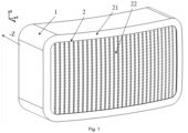
- the grill lamp comprises an opaque housing 1, and 2K outer lens 2 which are connected and form a cavity between them.
- Outer lens 2 consist of an opaque portion 21 and a translucent portion 22.
- a set of LEDs, serving as light sources, 41 is populated on at least one PCB 3.
- Light sources 41 are hidden behind opaque portion 21 of outer lens 2 to prevent direct illumination of the outer lens and are oriented transversally to the optical axis.
- a sheet-shaped light guide 5 with an overall planar shape is a planar or curved sheet following the outer lens 2's curvature.
- Frame X, Y, Z respectively represents the vertical, transversal and longitudinal directions of the vehicle when the grill lamp is mounted on it.
- Light guide 5 has a sheet shape, meaning that it is has a three-dimensional shape in X, Y and Z directions, with Z dimension significantly smaller than X and Y dimensions. Z dimension is called thickness.
- a narrow peripheral surface of the light guide 5 is its edge 53.
- Front 58 and back 59 surfaces of the light guide are faces larger than edge 53.
- the front face is also named observation face 58.
- the faces are curved and globally parallel to each other.
- Light guide 5 is placed backward parallel to outer lens 2 and is configured to receive light from light sources 41, either directly on in-coupling surface of edge 53, as shown in figure 2 , or through optical elements 56 located at its upper edge 53, as shown in figure 3 .
- optical elements 56 located at its upper edge 53, as shown in figure 3 .
- the absence or presence of optical elements 56 depends on the embodiment. The other features of the invention described are not affected by this variation.
- Light emitted by light sources 41 flows from optical elements 56 into the light guide 5 in a source-to-guide direction that is parallel to axis X in the drawings. Light is coupled into the light guide 5 and guided inside through total internal reflection, as will be explained in reference to figures 11 and 12 .
- a diffusive screen 6 is placed backward, parallel to back face 59 of light guide 5, and is following the shape of the light guide back face 59. Diffusive screen 6 keeps small distance to light guide 5 or is in physical contact with it, but it is a separate part made of a diffusive material.
- the front face, i.e. observation face 58, of diffusive screen 6 is patterned with a coloured printing 61 that darkens most of the screen except on ovals 62 aligned in columns parallel to X direction. Accordingly, diffusive screen 6 is able to diffuse light in the ovals 62 and absorb light elsewhere of its observation face.
- the printed colour may be black or any other colour matching with the expected aesthetic effect.
- the non printed ovals 62 of screen 6 can also be white printed to enhance the visual effect.
- a set of frustoconical holes 54 are created. They are obtained during the moulding of the light guide. Their conical shape is clearly compatible with an unmoulding step of the manufacturing.
- Holes 54 are crossing the light guide 5 along its thickness, in the Z direction.
- Holes 54 are arranged in perforation columns 52 between the light sources 41 and optical elements 56. Perforation columns 52 extend parallel to the source-to-guide direction (i.e. X direction).
- Holes 54 are elongated along the light guide body 5 with a widest dimension in the source-to-guide direction X. They have an elliptic cross section in any plane parallel to the light guide, i.e. parallel to X and Y directions.
- Holes 54 are facing non-printed ovals 62 of diffusive screen 6 and printed portions 61 of diffusive screen 6 are facing the solid portions of back face 59 of light guide 5. This will enhance the impression of patterned lit on appearance and expand it also for lit of appearance, as shown in figures 14 and 15 .
- All of the aligned holes 54 have projections along the source-to-guide (or X) direction. Projections intersect edge 53 and delimit projection areas 57 of edge 53, as shown in figure 10 .
- projection area 57 (grey coloured for a better understanding in figure 10 ) belong to the upper half holes 55 intersecting edge 53.
- Projection areas 57 are distinct from the locations of optical elements 56 and LEDs 41. They are at a distant with optical elements 56 in the source-to-guide direction X.
- cross-section C-C taken in a plane of figure 4 parallel to Z and X directions and intersecting the axis of one perforation column 52, shows the cut holes 54.
- Cross-section B-B of figure 8 taken in another plane parallel to Z, X directions and intersecting optical elements 56, is solid from top to bottom. Dotted lines show the cut holes 54 through the transparency.
- Figure 5 shows another embodiment of the light guide 5', with frustoconical elongated holes 54' having a rectangular cross-section in any plane parallel to the light guide, i.e. parallel to X and Y directions.
- the cross-section of the holes 54' modifies the visual aspect of the illumination of the grill lamp. It is thus decided to meet the aesthetical expectations of a designer.
- holes 54' are arranged as holes 54 of the previous embodiment, in columns parallel to X direction, with their greatest dimension "I” parallel du X direction, and their smallest dimension "w” perpendicular to it.
- the projections of holes 54' on edge 53 are also restricted to projection areas 57 that are spaced apart optical elements 56.
- diffusive screen 6 may also be modified by replacement of clear or white ovals 62 with clear or white rectangles (not shown).
- the matrix arrangement of holes 54 and 54' creates rows, along the Y direction, in addition to columns in the X direction. Such rows are part of the resulting visual effect of the grill lamp in lit state, but not part of the technical effect of the invention.
- holes 54" have unregular shapes. They are frustoconical and elongated along the X direction, with their greatest dimension "I” parallel du X direction, and their smallest dimension "w” perpendicularto it, but they are not arranged in rows and columns. However, the projections of all the holes 54" onto edge 53 of the light guide 5", along the source-to-guide direction X, are also restricted to projection areas 57 that do not overlap the locations of optical elements 56.
- light guides 5, 5' and 5" propagate the light emitted by LEDs 41 in the same way, as explained now in reference to figures 11 and 12 .
- Light rays 71 coupled in to light guide 5 from light source 41 are guided inside a light channel 51.
- a light channel 51 overlaps two adjacent perforation columns 52 and the part of light guide 5 located between them. Coupling in of rays 71 occurs through total internal reflections on side walls 59 of holes 54. Addressability of the light channels 51 is then possible by operating separately each one of light sources 41. The resulting optical effect is shown in figure 14 .
- light emitted by LED 41 mainly reaches third row holes (excluding the half-holes of the upper edge), apart for a few rays that are reflected by the side walls of the holes of the first and second rows of holes (excluding the half-holes of the upper edge). Then, light decouples in the third row, as show in figures 11 and 12 .
- through holes 54a of light guide 5a have a frustoconical shape, as holes 54, 54' and 54" of the previous embodiments, but the apex of the cone is inverted. In other words, holes 54a are larger close to diffusing screen 6 than at the observation face. Again, the resulting aesthetic effect is changed, but the technical effect of the invention remains. It is a matter of aesthetic choice by the designer of the grill lamp.
Landscapes
- Engineering & Computer Science (AREA)
- General Engineering & Computer Science (AREA)
- Physics & Mathematics (AREA)
- Mechanical Engineering (AREA)
- General Physics & Mathematics (AREA)
- Optics & Photonics (AREA)
- Illuminated Signs And Luminous Advertising (AREA)
- Arrangements Of Lighting Devices For Vehicle Interiors, Mounting And Supporting Thereof, Circuits Therefore (AREA)
Abstract
Description
- The technical field of the invention is illuminating devices for vehicles, in particular for vehicle exterior panels.
- Exterior panels of vehicles tend to be decorated and illuminated to render communication services, improve visibility or for aesthetic purposes.
- However, illuminating panels requires numerous light sources and complex devices made of a high number of parts, leading to an increase of the cost of the vehicle.
-
US7543971 discloses a planar light guide for use in a keypad, providing an illumination of the keys with a small number of light sources. - Such a light guide offers the advantage of reducing the number of light sources, compared with the number of illuminated keys. It is not adapted to exterior panels and has never been disclosed as adaptable to this application.
- With the purpose of offering a solution to illuminate a big area of an exterior panel, with a patterned lit appearance and a limited number of parts, the invention makes use of a two-dimensional light guide that has been adapted appropriately.
- According to the invention, the use of a two-dimensional light guide makes it possible to obtain a slim illuminated panel.
- Additionally, the position of the light sources and the arrangement of the two-dimensional light guide reduces the effect of the positioning of the light sources, i.e. increase the tolerance for loose positioning of the light sources.
- An object of the invention is a light guide designed to fit a vehicle panel, said light guide having a sheet shape with a predetermined thickness and at least one edge equipped with in-coupling surfaces able to accommodate light sources, such as LEDs, directed towards the light guide in a source-to-guide direction, characterised in that said sheet-shaped light guide comprises a plurality of through-holes along the thickness of the sheet-shaped light guide and wherein the in-coupling surfaces are positioned in locations on the edge and at a distant with the projections of the through-holes in the source-to-guide direction, and in that a cross-section of at least one of the through-holes has a an varying width along the thickness of the light guide.
- In the present description, the following terms are used with the following meanings:
- sheet shape: a three-dimensional shape with one dimension out of three significantly smaller than the two other dimensions. The smaller dimension is called thickness. The shape is delimited by two large surfaces, named faces, and one narrow peripheral surface, named edge. The faces are not necessarily planar. For instance, they can be curved. Because of the narrowness of the edge, the faces are globally parallel.,
- vehicle panel: exterior or interior vehicle body part, usually visible to an observer looking at it, if necessary, after removal of another covering part,
- observation face of an object: face intended to be seen by an observer looking at the object,
- source-to-guide direction: the main direction of a beam propagating from the light sources into the light guide, after coupling in at the in-coupling surfaces on the edge of the light guide,
- projection of the through holes in a direction: the intersection of lines passing through the holes and parallel to the direction with any surface not containing the direction,
- The exterior panel can be, for instance, a front grill.
- According to a particular embodiment, the through holes are arranged in columns that extend parallel to the source-to-guide direction. This renders a specific visual effect.
- According to a particular embodiment, at least some, preferably all, of the through-holes have an elongated shape with a widest dimension in the source-to-guide direction.
- According to a particular embodiment, the vehicle panel has an observation face, i.e. a face intended to be seen by an observer looking at the vehicle, and the cross-section of at least one of the through-holes has an increasing width along the thickness of the light guide when moving towards the observation face. In this embodiment, the brightness of the illumination can be increased because light is decoupled from all the through holes in the same direction. A diffusive screen can then be located on one side of the light guide and diffuse a bright light.
- One advantage of the elongated shape is to provide wider light channels in the light guide for propagating light. Another advantage is a better decoupling of the light and, therefore, a possibility to add milky filters, masks, or a combination of both.
- The elongated shape can have an elliptic or a rectangular cross section in a plane parallel to the two-dimensional light guide. This choice depends on the targeted visual effect.
- According to a particular embodiment, at least one of the through holes has a frustoconical cross section. This helps orientating the decoupled lights rays towards the observation face progressively and uniformly, thus illuminating the observation face of the panel.
- According to a particular embodiment, the in-coupling surface is a curved structure collimating light through the curve.
- According to another particular embodiment, the in-coupling region has an optical element, collimating the light into the light guide.
- According to a particular embodiment, the through holes are arranged in a matrix pattern.
- Another object of the invention is a grill lamp for a vehicle body panel, comprising a light guide as described above and a set of light sources mounted next to the optical interfaces and oriented so as to be directed parallel to the source-to-guide direction.
- The grill lamp may comprise a frame, possibly of a rectangular shape, surrounding the guide light and accommodating the light sources.
- In a particular embodiment, the grill lamp comprises a diffusive screen made of a different diffusive material and located next to the light guide. The diffusive screen may be coloured differently in locations facing the plain surface of the guide light and in locations facing the through-hole sections of the guide light.
- In a particular embodiment, the diffusive screen is coloured differently in locations facing the plain surface of the guide light and in locations facing the through-hole sections of the guide light.
- Thanks to the invention, the limited number of light sources can be addressable and controlled to create a light animation on the panel.
- Other advantages of the light guide according to the invention are:
- the absence of collimating features brings tolerance regarding the positioning of the light sources,
- the use of one large light guide reduces the need of an assembling process and avoids the cost of assembly tools,
- the required pattern of through holes can be obtained by moulding,
- a painting can be added on a portion of the light guide to create a frame, thus further reducing the number of parts,
- no masking parts are needed in the composition of the panel,
- the panel is adapted to very slim locations,
- the illuminated panel has a good homogeneity for high angular views,
- although the number of light sources is limited, partial addressability of the light sources allows some animation with a good homogeneity,
- Other objects of the invention are a vehicle body panel fitted with a light guide according to the invention and a vehicle body panel comprising a grill lamp according to the invention.
- The invention will be better understood by reading the description of the following non-limiting examples, illustrated by the following figures:
-
figure 1 is a perspective view of a real grill lamp according to a first embodiment of the invention, -
figure 2 is a partial and schematic representation of the grill lamp offigure 1 , -
figure 3 is a perspective view of a diffusive screen, -
figure 4 is a perspective view of the light guide according to a first embodiment, -
figure 5 is a perspective view of the light guide according to a second embodiment, -
figure 6 is a perspective view of the light guide according to a third embodiment, -
figure 7 is a cross section along plane A-A, -
figure 8 is a cross section along plane B-B, -
figure 9 is a cross section along plane C-C, -
figure 10 is a top-view of the light guide showing the projection of the through holes on the upper edge of the light guide, -
figure 11 shows, in the light guide offigure 4 , the propagation of light emitted by the light sources, -
figure 12 shows, in the light guide offigure 10 , the propagation of light emitted by the light sources, -
figures 13a, 13b and 13c shows light rays propagating in the light guide and decoupling toward the diffusive screen, -
figure 14 is a view of the observation face of the grill lamp with the complete set of LEDs on, -
figure 15 is a view of the observation face of the grill lamp with only one LED on, -
figure 16 is a cross section along plane B-B of another embodiment of the light guide, -
figure 17 is a cross section along plane B-B of yet another embodiment of the light guide, - The grill lamp represented on the drawings is intended to cover a large area of a vehicle body panel, for instance at the front of a vehicle. Its function is to illuminate the panel in an original way. The grill lamp in this embodiment of the invention is a slim object with a small footprint, that can be located at the front of a vehicle. In this example, when an observer is looking at the vehicle, he or she can see the front face of the vehicle. The front face of the grill lamp visible by the observer, as well as any constituting part of the grill lamp, has an observation face directed towards the exterior of the vehicle (forward direction Z of the vehicle) and a hidden face directed towards the interior of the vehicle (rearward direction -Z of the vehicle).
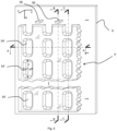
- In
figure 2 , all parts are shown. The grill lamp comprises anopaque housing 1, and 2Kouter lens 2 which are connected and form a cavity between them.Outer lens 2 consist of anopaque portion 21 and atranslucent portion 22. In the cavity betweenhousing 1 andouter lens 2, a set of LEDs, serving as light sources, 41 is populated on at least onePCB 3.Light sources 41 are hidden behindopaque portion 21 ofouter lens 2 to prevent direct illumination of the outer lens and are oriented transversally to the optical axis. A sheet-shapedlight guide 5 with an overall planar shape is a planar or curved sheet following theouter lens 2's curvature. - Frame X, Y, Z respectively represents the vertical, transversal and longitudinal directions of the vehicle when the grill lamp is mounted on it.
-
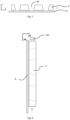
Light guide 5 has a sheet shape, meaning that it is has a three-dimensional shape in X, Y and Z directions, with Z dimension significantly smaller than X and Y dimensions. Z dimension is called thickness. A narrow peripheral surface of thelight guide 5 is itsedge 53.Front 58 and back 59 surfaces of the light guide are faces larger thanedge 53. The front face is also namedobservation face 58. The faces are curved and globally parallel to each other. -
Light guide 5 is placed backward parallel toouter lens 2 and is configured to receive light fromlight sources 41, either directly on in-coupling surface ofedge 53, as shown infigure 2 , or throughoptical elements 56 located at itsupper edge 53, as shown infigure 3 . The absence or presence ofoptical elements 56 depends on the embodiment. The other features of the invention described are not affected by this variation. - The
optical elements 56 are performing the collimation of the light emitted by thelight sources 41 into thelight guide 5. As previously mentioned, in alternative embodiments, theLED light source 41 is directly mounted on in-coupling surface ofedge 53. - Light emitted by
light sources 41 flows fromoptical elements 56 into thelight guide 5 in a source-to-guide direction that is parallel to axis X in the drawings. Light is coupled into thelight guide 5 and guided inside through total internal reflection, as will be explained in reference tofigures 11 and 12 . - A
diffusive screen 6 is placed backward, parallel to backface 59 oflight guide 5, and is following the shape of the light guide backface 59.Diffusive screen 6 keeps small distance tolight guide 5 or is in physical contact with it, but it is a separate part made of a diffusive material. - As shown in
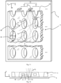
figure 4 , the front face, i.e.observation face 58, ofdiffusive screen 6 is patterned with acoloured printing 61 that darkens most of the screen except onovals 62 aligned in columns parallel to X direction. Accordingly,diffusive screen 6 is able to diffuse light in theovals 62 and absorb light elsewhere of its observation face. The printed colour may be black or any other colour matching with the expected aesthetic effect. The non printedovals 62 ofscreen 6 can also be white printed to enhance the visual effect. - As shown by
figure 4 , in thelight guide 5, a set offrustoconical holes 54 are created. They are obtained during the moulding of the light guide. Their conical shape is clearly compatible with an unmoulding step of the manufacturing.Holes 54 are crossing thelight guide 5 along its thickness, in the Z direction.Holes 54 are arranged inperforation columns 52 between thelight sources 41 andoptical elements 56.Perforation columns 52 extend parallel to the source-to-guide direction (i.e. X direction).Holes 54 are elongated along thelight guide body 5 with a widest dimension in the source-to-guide direction X. They have an elliptic cross section in any plane parallel to the light guide, i.e. parallel to X and Y directions. -
Holes 54 are facingnon-printed ovals 62 ofdiffusive screen 6 and printedportions 61 ofdiffusive screen 6 are facing the solid portions ofback face 59 oflight guide 5. This will enhance the impression of patterned lit on appearance and expand it also for lit of appearance, as shown infigures 14 and 15 . - All of the aligned
holes 54 have projections along the source-to-guide (or X) direction. Projections intersectedge 53 and delimitprojection areas 57 ofedge 53, as shown infigure 10 . In this embodiment, projection area 57 (grey coloured for a better understanding infigure 10 ) belong to the upper half holes 55 intersectingedge 53.Projection areas 57 are distinct from the locations ofoptical elements 56 andLEDs 41. They are at a distant withoptical elements 56 in the source-to-guide direction X. - In
figure 9 , cross-section C-C, taken in a plane offigure 4 parallel to Z and X directions and intersecting the axis of oneperforation column 52, shows the cut holes 54. Cross-section B-B offigure 8 , taken in another plane parallel to Z, X directions and intersectingoptical elements 56, is solid from top to bottom. Dotted lines show the cut holes 54 through the transparency. -
Figure 5 shows another embodiment of the light guide 5', with frustoconical elongated holes 54' having a rectangular cross-section in any plane parallel to the light guide, i.e. parallel to X and Y directions. The cross-section of the holes 54' modifies the visual aspect of the illumination of the grill lamp. It is thus decided to meet the aesthetical expectations of a designer. - Apart from the cross-section, holes 54' are arranged as
holes 54 of the previous embodiment, in columns parallel to X direction, with their greatest dimension "I" parallel du X direction, and their smallest dimension "w" perpendicular to it. The projections of holes 54' onedge 53 are also restricted toprojection areas 57 that are spaced apartoptical elements 56. With a light guide 5' having rectangular cross-section holes 54',diffusive screen 6 may also be modified by replacement of clear orwhite ovals 62 with clear or white rectangles (not shown). - In the embodiments of
figures 4 and5 , the matrix arrangement ofholes 54 and 54' creates rows, along the Y direction, in addition to columns in the X direction. Such rows are part of the resulting visual effect of the grill lamp in lit state, but not part of the technical effect of the invention. - In
figure 6 , holes 54" have unregular shapes. They are frustoconical and elongated along the X direction, with their greatest dimension "I" parallel du X direction, and their smallest dimension "w" perpendicularto it, but they are not arranged in rows and columns. However, the projections of all theholes 54" ontoedge 53 of thelight guide 5", along the source-to-guide direction X, are also restricted toprojection areas 57 that do not overlap the locations ofoptical elements 56. - Accordingly, light guides 5, 5' and 5" propagate the light emitted by
LEDs 41 in the same way, as explained now in reference tofigures 11 and 12 . - Light rays 71 coupled in to
light guide 5 fromlight source 41 are guided inside alight channel 51. Alight channel 51 overlaps twoadjacent perforation columns 52 and the part oflight guide 5 located between them. Coupling in ofrays 71 occurs through total internal reflections onside walls 59 ofholes 54. Addressability of thelight channels 51 is then possible by operating separately each one oflight sources 41. The resulting optical effect is shown infigure 14 . - Part of
rays 71 guided inlight channels 51 are leaking through thehole side walls 59 out oflight guide 5 and can reach thediffusive screen 6 inovals 62 just behind light guide holes 54 or can be coupled again into the light guide.Rays 72 which are reachingdiffusive screen 6 inovals 62 are reflected and partially redirected asrays 73 towards clear portion ofouter lens 2 to be visible to the observer at an observation face of the panel. In consequence, the main contribution of the light seen by the observer located in front of the observation face of thelight guide 5 comes fromovals 62 of diffusive screen. So, the lit-on appearance is patterned as defined byperforation columns 52. - The interest of the technical features of
light guide 5 is that holes 54 in sheet-shapedlight guide 5 have double role. A first one is to guide light betweenperforation columns 52 causing thelight channels 51 addressability. A second one is to partially decouple light in to the cavity created byholes 54. The decoupled light then is reflected towards the observer by white orclear portion 62 ofdiffusive screen 6.Light guide 5 itself is not producing any light perceived by the observer but only guides the light in thelight channels 51 and provides it into the cavities created by theholes diffusive screen 6. - In
figure 13 , one can see a realistic propagation of light rays and their decoupling from the light guide when exiting theholes 54. - For the sake of clarify, light rays are represented separately in
figures 13a, 13b and 13c , but it should be understood that the propagated rays are superposed in the light guide. - In
figure 13a , light emitted byLED 41 is coupled in onto the light guide and propagated inlight channel 51. Most of the rays propagate inlight channel 51 directly to the second row of holes. A few rays meet the side walls of two adjacent holes of the first row of holes and, because of incident angle, reflect totally towards second row holes. All the rays meeting the second row of holes decouple from the light guide because of their incident angle on the walls of the holes, as show infigures 11 and 12 . The rays then meet the clear or white ovals of thediffusive screen 6 and light is diffused towards the observation face, in the Z direction. - In
figure 13b , light emitted byLED 41 mainly reaches third row holes (excluding the half-holes of the upper edge), apart for a few rays that are reflected by the side walls of the holes of the first and second rows of holes (excluding the half-holes of the upper edge). Then, light decouples in the third row, as show infigures 11 and 12 . - In
figure 13c , light emitted fromLED 41 is mainly reflected by side walls of the holes of preceding rows. The total reflection keeps light rays in the light channel, until the incident angle is such that light decouples from the light guide, in the fourth row of holes (excluding the half-holes of the upper edge). - The resulting optical effect of the grill lamp is illustrated by
figures 14 and 15 , where one can see that light emitted from holes of a same column have the same brightness, thanks to the propagation in thelight channels 51. However, eachlight channel 51 can be individually controlled by individual control of theLED 41 feeding thelight channel 51. - In the embodiment of
figure 16 , throughholes 54a oflight guide 5a have a frustoconical shape, asholes holes 54a are larger close to diffusingscreen 6 than at the observation face. Again, the resulting aesthetic effect is changed, but the technical effect of the invention remains. It is a matter of aesthetic choice by the designer of the grill lamp. - In the embodiment of
figure 17 , the cross section ofholes light guide 5b is irregular. The shape ofholes holes optical elements 56. -
- X: source-to-guide direction
- I : ... greatest dimension of holes
- w : ... smallest dimension of holes
- 1 : ...housing
- 2 : ...outer lens
- 21 : ...opaque portion
- 22 : ...translucent portion
- 3 : ...PCB
- 41 : ...light sources, LEDs
- 5 : ...light guide
- 51 : ...light channels
- 52 : ...perforation columns
- 53 : ...edge
- 54, 54', 54"", 54a, 54b : ...through holes
- 55 : ...half holes
- 56 : ...optical elements
- 57 : ... projection area
- 58 : ...observation face
- 59 : ...hole side wall
- 6 : ... diffusive screen
- 61 : ...coloured printing
- 62 : ...ovals
Claims (10)
Priority Applications (2)
| Application Number | Priority Date | Filing Date | Title |
|---|---|---|---|
| EP23220243.2A EP4578732A1 (en) | 2023-12-27 | 2023-12-27 | A light guide designed for use in a vehicle |
| US19/002,960 US12492798B2 (en) | 2023-12-27 | 2024-12-27 | Light guide designed for use in a vehicle |
Applications Claiming Priority (1)
| Application Number | Priority Date | Filing Date | Title |
|---|---|---|---|
| EP23220243.2A EP4578732A1 (en) | 2023-12-27 | 2023-12-27 | A light guide designed for use in a vehicle |
Publications (1)
| Publication Number | Publication Date |
|---|---|
| EP4578732A1 true EP4578732A1 (en) | 2025-07-02 |
Family
ID=89385881
Family Applications (1)
| Application Number | Title | Priority Date | Filing Date |
|---|---|---|---|
| EP23220243.2A Pending EP4578732A1 (en) | 2023-12-27 | 2023-12-27 | A light guide designed for use in a vehicle |
Country Status (2)
| Country | Link |
|---|---|
| US (1) | US12492798B2 (en) |
| EP (1) | EP4578732A1 (en) |
Citations (7)
| Publication number | Priority date | Publication date | Assignee | Title |
|---|---|---|---|---|
| US7543971B2 (en) | 2006-10-27 | 2009-06-09 | Lite-On Technology Corporation | Light guide for use in a keypad |
| EP2735789A2 (en) * | 2012-11-26 | 2014-05-28 | Bang & Olufsen A/S | Lens arrangement with light guide and internal reflecting elements |
| EP3012522B1 (en) * | 2014-10-24 | 2017-07-19 | Stanley Electric Co., Ltd. | Vehicle lighting unit |
| US20210062993A1 (en) * | 2018-02-19 | 2021-03-04 | Marelli Automotive Lighting France | Signaling Device for a Motor Vehicle |
| US20220099266A1 (en) * | 2020-09-28 | 2022-03-31 | Hyundai Motor Company | Lighting apparatus of grille for automobile |
| CN216783452U (en) * | 2021-10-09 | 2022-06-21 | 宁波信泰机械有限公司 | Face guard and car light-emitting grille of car light-emitting grille |
| US20230128040A1 (en) * | 2021-10-26 | 2023-04-27 | Hyundai Mobis Co., Ltd. | Communication device and method for vehicle |
Family Cites Families (1)
| Publication number | Priority date | Publication date | Assignee | Title |
|---|---|---|---|---|
| DE102023122482A1 (en) * | 2023-08-22 | 2025-02-27 | Marelli Automotive Lighting Reutlingen (Germany) GmbH | lighting device, in particular for a motor vehicle |
-
2023
- 2023-12-27 EP EP23220243.2A patent/EP4578732A1/en active Pending
-
2024
- 2024-12-27 US US19/002,960 patent/US12492798B2/en active Active
Patent Citations (7)
| Publication number | Priority date | Publication date | Assignee | Title |
|---|---|---|---|---|
| US7543971B2 (en) | 2006-10-27 | 2009-06-09 | Lite-On Technology Corporation | Light guide for use in a keypad |
| EP2735789A2 (en) * | 2012-11-26 | 2014-05-28 | Bang & Olufsen A/S | Lens arrangement with light guide and internal reflecting elements |
| EP3012522B1 (en) * | 2014-10-24 | 2017-07-19 | Stanley Electric Co., Ltd. | Vehicle lighting unit |
| US20210062993A1 (en) * | 2018-02-19 | 2021-03-04 | Marelli Automotive Lighting France | Signaling Device for a Motor Vehicle |
| US20220099266A1 (en) * | 2020-09-28 | 2022-03-31 | Hyundai Motor Company | Lighting apparatus of grille for automobile |
| CN216783452U (en) * | 2021-10-09 | 2022-06-21 | 宁波信泰机械有限公司 | Face guard and car light-emitting grille of car light-emitting grille |
| US20230128040A1 (en) * | 2021-10-26 | 2023-04-27 | Hyundai Mobis Co., Ltd. | Communication device and method for vehicle |
Also Published As
| Publication number | Publication date |
|---|---|
| US20250216050A1 (en) | 2025-07-03 |
| US12492798B2 (en) | 2025-12-09 |
Similar Documents
| Publication | Publication Date | Title |
|---|---|---|
| JP2021140930A (en) | Illumination device and game machine | |
| JP7521883B2 (en) | Lighting and/or signalling devices for motor vehicles | |
| EP4158243B1 (en) | Homogenous lit line image vehicle lamp assembly | |
| JP2011244840A (en) | Display apparatus for game machine, and game machine with the same | |
| CN220038269U (en) | Vehicle ornament | |
| US11994265B2 (en) | Lighting assembly for a vehicle and method for producing a lighting assembly | |
| EP2011133A1 (en) | Illuminating of an electrical device | |
| EP3184363B1 (en) | Lighting device for an interior panel of a vehicle | |
| EP4578732A1 (en) | A light guide designed for use in a vehicle | |
| DE102020109841B4 (en) | ARRANGEMENT AND VEHICLE | |
| JP4313327B2 (en) | Information display device for each game machine | |
| KR20190128574A (en) | Automotive lighting and/or signaling device | |
| JP7571355B2 (en) | Light guide plate and display module | |
| JP5828687B2 (en) | Display light guide plate and display device including display light guide plate | |
| CN118757712A (en) | Vehicle accessories | |
| KR20240175562A (en) | Lamp for vehicle and vehicle including the same | |
| CN212584882U (en) | Automobile lighting device for realizing 3D dynamic visual effect by utilizing peripheral drift illusion principle | |
| JP2002197914A (en) | Light guide plate of backlight unit | |
| JP2024050116A (en) | Lighting equipment | |
| JP7818470B2 (en) | Vehicle lighting fixtures | |
| WO2012108101A1 (en) | Display instrument | |
| CN222629249U (en) | Vehicle interior trim structure and vehicle | |
| EP4375568A1 (en) | Illumination assembly for a vehicle | |
| EP4311977A1 (en) | Automotive lighting appliance | |
| JP2025123861A (en) | Vehicle lighting structure |
Legal Events
| Date | Code | Title | Description |
|---|---|---|---|
| PUAI | Public reference made under article 153(3) epc to a published international application that has entered the european phase |
Free format text: ORIGINAL CODE: 0009012 |
|
| STAA | Information on the status of an ep patent application or granted ep patent |
Free format text: STATUS: THE APPLICATION HAS BEEN PUBLISHED |
|
| AK | Designated contracting states |
Kind code of ref document: A1 Designated state(s): AL AT BE BG CH CY CZ DE DK EE ES FI FR GB GR HR HU IE IS IT LI LT LU LV MC ME MK MT NL NO PL PT RO RS SE SI SK SM TR |
|
| STAA | Information on the status of an ep patent application or granted ep patent |
Free format text: STATUS: REQUEST FOR EXAMINATION WAS MADE |
|
| 17P | Request for examination filed |
Effective date: 20251204 |
|
| P01 | Opt-out of the competence of the unified patent court (upc) registered |
Free format text: CASE NUMBER: UPC_APP_0014934_4578732/2025 Effective date: 20251127 |