EP4578731A1 - Lighting assembly - Google Patents
Lighting assembly Download PDFInfo
- Publication number
- EP4578731A1 EP4578731A1 EP23220520.3A EP23220520A EP4578731A1 EP 4578731 A1 EP4578731 A1 EP 4578731A1 EP 23220520 A EP23220520 A EP 23220520A EP 4578731 A1 EP4578731 A1 EP 4578731A1
- Authority
- EP
- European Patent Office
- Prior art keywords
- light
- assembly according
- emitting points
- light source
- display
- Prior art date
- Legal status (The legal status is an assumption and is not a legal conclusion. Google has not performed a legal analysis and makes no representation as to the accuracy of the status listed.)
- Pending
Links
Images


Classifications
-
- B—PERFORMING OPERATIONS; TRANSPORTING
- B60—VEHICLES IN GENERAL
- B60Q—ARRANGEMENT OF SIGNALLING OR LIGHTING DEVICES, THE MOUNTING OR SUPPORTING THEREOF OR CIRCUITS THEREFOR, FOR VEHICLES IN GENERAL
- B60Q1/00—Arrangement of optical signalling or lighting devices, the mounting or supporting thereof or circuits therefor
- B60Q1/0029—Spatial arrangement
- B60Q1/0041—Spatial arrangement of several lamps in relation to each other
-
- B—PERFORMING OPERATIONS; TRANSPORTING
- B60—VEHICLES IN GENERAL
- B60Q—ARRANGEMENT OF SIGNALLING OR LIGHTING DEVICES, THE MOUNTING OR SUPPORTING THEREOF OR CIRCUITS THEREFOR, FOR VEHICLES IN GENERAL
- B60Q1/00—Arrangement of optical signalling or lighting devices, the mounting or supporting thereof or circuits therefor
- B60Q1/26—Arrangement of optical signalling or lighting devices, the mounting or supporting thereof or circuits therefor the devices being primarily intended to indicate the vehicle, or parts thereof, or to give signals, to other traffic
- B60Q1/2607—Arrangement of optical signalling or lighting devices, the mounting or supporting thereof or circuits therefor the devices being primarily intended to indicate the vehicle, or parts thereof, or to give signals, to other traffic comprising at least two indicating lamps
-
- B—PERFORMING OPERATIONS; TRANSPORTING
- B60—VEHICLES IN GENERAL
- B60Q—ARRANGEMENT OF SIGNALLING OR LIGHTING DEVICES, THE MOUNTING OR SUPPORTING THEREOF OR CIRCUITS THEREFOR, FOR VEHICLES IN GENERAL
- B60Q1/00—Arrangement of optical signalling or lighting devices, the mounting or supporting thereof or circuits therefor
- B60Q1/26—Arrangement of optical signalling or lighting devices, the mounting or supporting thereof or circuits therefor the devices being primarily intended to indicate the vehicle, or parts thereof, or to give signals, to other traffic
- B60Q1/50—Arrangement of optical signalling or lighting devices, the mounting or supporting thereof or circuits therefor the devices being primarily intended to indicate the vehicle, or parts thereof, or to give signals, to other traffic for indicating other intentions or conditions, e.g. request for waiting or overtaking
- B60Q1/503—Arrangement of optical signalling or lighting devices, the mounting or supporting thereof or circuits therefor the devices being primarily intended to indicate the vehicle, or parts thereof, or to give signals, to other traffic for indicating other intentions or conditions, e.g. request for waiting or overtaking using luminous text or symbol displays in or on the vehicle, e.g. static text
- B60Q1/5035—Arrangement of optical signalling or lighting devices, the mounting or supporting thereof or circuits therefor the devices being primarily intended to indicate the vehicle, or parts thereof, or to give signals, to other traffic for indicating other intentions or conditions, e.g. request for waiting or overtaking using luminous text or symbol displays in or on the vehicle, e.g. static text electronic displays
-
- F—MECHANICAL ENGINEERING; LIGHTING; HEATING; WEAPONS; BLASTING
- F21—LIGHTING
- F21S—NON-PORTABLE LIGHTING DEVICES; SYSTEMS THEREOF; VEHICLE LIGHTING DEVICES SPECIALLY ADAPTED FOR VEHICLE EXTERIORS
- F21S43/00—Signalling devices specially adapted for vehicle exteriors, e.g. brake lamps, direction indicator lights or reversing lights
- F21S43/10—Signalling devices specially adapted for vehicle exteriors, e.g. brake lamps, direction indicator lights or reversing lights characterised by the light source
- F21S43/13—Signalling devices specially adapted for vehicle exteriors, e.g. brake lamps, direction indicator lights or reversing lights characterised by the light source characterised by the type of light source
- F21S43/14—Light emitting diodes [LED]
-
- F—MECHANICAL ENGINEERING; LIGHTING; HEATING; WEAPONS; BLASTING
- F21—LIGHTING
- F21S—NON-PORTABLE LIGHTING DEVICES; SYSTEMS THEREOF; VEHICLE LIGHTING DEVICES SPECIALLY ADAPTED FOR VEHICLE EXTERIORS
- F21S43/00—Signalling devices specially adapted for vehicle exteriors, e.g. brake lamps, direction indicator lights or reversing lights
- F21S43/10—Signalling devices specially adapted for vehicle exteriors, e.g. brake lamps, direction indicator lights or reversing lights characterised by the light source
- F21S43/13—Signalling devices specially adapted for vehicle exteriors, e.g. brake lamps, direction indicator lights or reversing lights characterised by the light source characterised by the type of light source
- F21S43/14—Light emitting diodes [LED]
- F21S43/145—Surface emitters, e.g. organic light emitting diodes [OLED]
-
- F—MECHANICAL ENGINEERING; LIGHTING; HEATING; WEAPONS; BLASTING
- F21—LIGHTING
- F21S—NON-PORTABLE LIGHTING DEVICES; SYSTEMS THEREOF; VEHICLE LIGHTING DEVICES SPECIALLY ADAPTED FOR VEHICLE EXTERIORS
- F21S43/00—Signalling devices specially adapted for vehicle exteriors, e.g. brake lamps, direction indicator lights or reversing lights
- F21S43/10—Signalling devices specially adapted for vehicle exteriors, e.g. brake lamps, direction indicator lights or reversing lights characterised by the light source
- F21S43/13—Signalling devices specially adapted for vehicle exteriors, e.g. brake lamps, direction indicator lights or reversing lights characterised by the light source characterised by the type of light source
- F21S43/15—Strips of light sources
-
- F—MECHANICAL ENGINEERING; LIGHTING; HEATING; WEAPONS; BLASTING
- F21—LIGHTING
- F21S—NON-PORTABLE LIGHTING DEVICES; SYSTEMS THEREOF; VEHICLE LIGHTING DEVICES SPECIALLY ADAPTED FOR VEHICLE EXTERIORS
- F21S43/00—Signalling devices specially adapted for vehicle exteriors, e.g. brake lamps, direction indicator lights or reversing lights
- F21S43/20—Signalling devices specially adapted for vehicle exteriors, e.g. brake lamps, direction indicator lights or reversing lights characterised by refractors, transparent cover plates, light guides or filters
- F21S43/235—Light guides
- F21S43/236—Light guides characterised by the shape of the light guide
- F21S43/237—Light guides characterised by the shape of the light guide rod-shaped
-
- F—MECHANICAL ENGINEERING; LIGHTING; HEATING; WEAPONS; BLASTING
- F21—LIGHTING
- F21S—NON-PORTABLE LIGHTING DEVICES; SYSTEMS THEREOF; VEHICLE LIGHTING DEVICES SPECIALLY ADAPTED FOR VEHICLE EXTERIORS
- F21S43/00—Signalling devices specially adapted for vehicle exteriors, e.g. brake lamps, direction indicator lights or reversing lights
- F21S43/20—Signalling devices specially adapted for vehicle exteriors, e.g. brake lamps, direction indicator lights or reversing lights characterised by refractors, transparent cover plates, light guides or filters
- F21S43/235—Light guides
- F21S43/236—Light guides characterised by the shape of the light guide
- F21S43/239—Light guides characterised by the shape of the light guide plate-shaped
-
- F—MECHANICAL ENGINEERING; LIGHTING; HEATING; WEAPONS; BLASTING
- F21—LIGHTING
- F21S—NON-PORTABLE LIGHTING DEVICES; SYSTEMS THEREOF; VEHICLE LIGHTING DEVICES SPECIALLY ADAPTED FOR VEHICLE EXTERIORS
- F21S43/00—Signalling devices specially adapted for vehicle exteriors, e.g. brake lamps, direction indicator lights or reversing lights
- F21S43/20—Signalling devices specially adapted for vehicle exteriors, e.g. brake lamps, direction indicator lights or reversing lights characterised by refractors, transparent cover plates, light guides or filters
- F21S43/235—Light guides
- F21S43/242—Light guides characterised by the emission area
- F21S43/243—Light guides characterised by the emission area emitting light from one or more of its extremities
-
- F—MECHANICAL ENGINEERING; LIGHTING; HEATING; WEAPONS; BLASTING
- F21—LIGHTING
- F21S—NON-PORTABLE LIGHTING DEVICES; SYSTEMS THEREOF; VEHICLE LIGHTING DEVICES SPECIALLY ADAPTED FOR VEHICLE EXTERIORS
- F21S43/00—Signalling devices specially adapted for vehicle exteriors, e.g. brake lamps, direction indicator lights or reversing lights
- F21S43/20—Signalling devices specially adapted for vehicle exteriors, e.g. brake lamps, direction indicator lights or reversing lights characterised by refractors, transparent cover plates, light guides or filters
- F21S43/235—Light guides
- F21S43/242—Light guides characterised by the emission area
- F21S43/245—Light guides characterised by the emission area emitting light from one or more of its major surfaces
-
- F—MECHANICAL ENGINEERING; LIGHTING; HEATING; WEAPONS; BLASTING
- F21—LIGHTING
- F21S—NON-PORTABLE LIGHTING DEVICES; SYSTEMS THEREOF; VEHICLE LIGHTING DEVICES SPECIALLY ADAPTED FOR VEHICLE EXTERIORS
- F21S43/00—Signalling devices specially adapted for vehicle exteriors, e.g. brake lamps, direction indicator lights or reversing lights
- F21S43/20—Signalling devices specially adapted for vehicle exteriors, e.g. brake lamps, direction indicator lights or reversing lights characterised by refractors, transparent cover plates, light guides or filters
- F21S43/2605—Refractors
- F21S43/2621—Refractors characterised by the properties of the light beam shaping surface
- F21S43/26271—Refractors characterised by the properties of the light beam shaping surface using micro-optics, e.g. micro-lenses or micro-structures
-
- F—MECHANICAL ENGINEERING; LIGHTING; HEATING; WEAPONS; BLASTING
- F21—LIGHTING
- F21S—NON-PORTABLE LIGHTING DEVICES; SYSTEMS THEREOF; VEHICLE LIGHTING DEVICES SPECIALLY ADAPTED FOR VEHICLE EXTERIORS
- F21S43/00—Signalling devices specially adapted for vehicle exteriors, e.g. brake lamps, direction indicator lights or reversing lights
- F21S43/20—Signalling devices specially adapted for vehicle exteriors, e.g. brake lamps, direction indicator lights or reversing lights characterised by refractors, transparent cover plates, light guides or filters
- F21S43/265—Transparent cover plates, e.g. for protecting the interior of the signalling devices against environmental influences
-
- F—MECHANICAL ENGINEERING; LIGHTING; HEATING; WEAPONS; BLASTING
- F21—LIGHTING
- F21S—NON-PORTABLE LIGHTING DEVICES; SYSTEMS THEREOF; VEHICLE LIGHTING DEVICES SPECIALLY ADAPTED FOR VEHICLE EXTERIORS
- F21S43/00—Signalling devices specially adapted for vehicle exteriors, e.g. brake lamps, direction indicator lights or reversing lights
- F21S43/40—Signalling devices specially adapted for vehicle exteriors, e.g. brake lamps, direction indicator lights or reversing lights characterised by the combination of reflectors and refractors
- F21S43/402—Total internal reflection [TIR] collimators
-
- H—ELECTRICITY
- H10—SEMICONDUCTOR DEVICES; ELECTRIC SOLID-STATE DEVICES NOT OTHERWISE PROVIDED FOR
- H10W—GENERIC PACKAGES, INTERCONNECTIONS, CONNECTORS OR OTHER CONSTRUCTIONAL DETAILS OF DEVICES COVERED BY CLASS H10
- H10W90/00—Package configurations
Definitions
- the present invention relates to a lighting assembly, in particular for car light clusters.
- mini-LED array display In some applications, e.g., in car light clusters, it is known to place a mini-LED array display alongside one or more lighting devices of more conventional type. Since the mini-LED array display has a very high resolution by virtue of the small size and very small distance between the mini-LEDs, it is used indeed to produce images, logos, or other information. Instead, the lighting devices alongside the display, for example made of LEDs, light guides, and/or reflectors, are used to generate simpler lighting effects, for example, in the case of the light cluster, lighting and signal light functions, e.g., brake and tail lights.
- lighting devices alongside the display for example made of LEDs, light guides, and/or reflectors, are used to generate simpler lighting effects, for example, in the case of the light cluster, lighting and signal light functions, e.g., brake and tail lights.
- Such an object is achieved by a lighting assembly according to claim 1 and a car light cluster according to claim 16.
- the first point light sources 12 are mini-LEDs.
Landscapes
- Engineering & Computer Science (AREA)
- General Engineering & Computer Science (AREA)
- Physics & Mathematics (AREA)
- Microelectronics & Electronic Packaging (AREA)
- Optics & Photonics (AREA)
- Mechanical Engineering (AREA)
- Non-Portable Lighting Devices Or Systems Thereof (AREA)
Abstract
A lighting assembly, in particular for a car headlight (40), comprises a display (10), an array of first point light sources (12) suitable for generating a first light effect on the display (10), and at least one optical element (14) placed alongside the display (10) and suitable for generating a second light effect. The optical element (14) comprises at least a second light source (16) and at least one optical structure (18) coupled to the at least a second light source (16) and configured to form a plurality of light-emitting points (20) which, when the second light source (16) is activated, generate the second light effect in combination. The distance (D1; D2) between adjacent light-emitting points (20) of at least one portion of said plurality of light-emitting points is substantially uniform and substantially equal to the distance (P1; P2) between the first point light sources (12).
Description
- The present invention relates to a lighting assembly, in particular for car light clusters.
- In some applications, e.g., in car light clusters, it is known to place a mini-LED array display alongside one or more lighting devices of more conventional type. Since the mini-LED array display has a very high resolution by virtue of the small size and very small distance between the mini-LEDs, it is used indeed to produce images, logos, or other information. Instead, the lighting devices alongside the display, for example made of LEDs, light guides, and/or reflectors, are used to generate simpler lighting effects, for example, in the case of the light cluster, lighting and signal light functions, e.g., brake and tail lights.
- One limitation of these combinations of lighting devices lies precisely in the different rendering of the light effect in terms of resolution and definition. Indeed, especially when the two different lighting devices are placed side-by-side, the effect of unevenness, i.e., the interruption, between the two light effects can be clearly perceived. In a context such as that of premium cars, in which the search for increasingly distinctive and defined lighting effects is exacerbated, such a discontinuity is poorly tolerated.
- Therefore, there is an increasing need to make the overall light effect produced by the combination of a display, e.g., a mini-LED array, and LED lighting elements and related optical devices as uniform and continuous as possible, as described above.
- Thus, it is the object of the present invention to suggest a lighting assembly of the aforesaid type, in particular for car light clusters, but capable of solving the drawbacks of lighting systems according to the prior art.
- Such an object is achieved by a lighting assembly according to
claim 1 and a car light cluster according toclaim 16. - The dependent claims describe preferred or advantageous embodiments of the lighting assembly.
- The features and advantages of lighting assembly according to the invention will be apparent from the following description of preferred embodiments thereof, given by way of non-limiting indication, with reference to the accompanying drawings, in which:
-
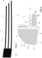
figure 1 is a front view of an example of a lighting assembly according to the invention; -
figure 2 is an enlarged view of the detail in the circle infigure 1 ; -
figure 3 is an example of a car light cluster, which incorporates the lighting assembly infigure 1 ; -
figure 4 is an exploded perspective view of the car light cluster; -
figure 5 is a diagrammatic top view of an embodiment of the lighting assembly according to the invention; -
figure 5a is a vertical section view of part of the assembly infigure 5 ; -
figure 6 is a diagrammatic top view of a further embodiment of the lighting assembly according to the invention; -
figure 7 is a diagrammatic top view of a further embodiment of the lighting assembly according to the invention; -
figures 8 and 8a are diagrammatic top and side views, respectively, of a further embodiment of the lighting assembly according to the invention; -
figure 9 is a diagrammatic top view of a further embodiment of the lighting assembly according to the invention; and -
figure 10 is a diagrammatic top view of a further embodiment of the lighting assembly according to the invention. - The following description refers to a lighting assembly used in a car headlight. However, it is apparent that the lighting assembly of the present invention can be advantageously employed in several applications, possibly with appropriate adaptations, where, due to regulatory constraints, rather than to meet technical or economic requirements, there is a need to generate, either simultaneously or in sequence, a first light effect with a display with an array of point light sources, e.g., mini-LEDs, and a second light effect using a different technology based on one or more light sources coupled to optical structures, e.g., reflectors and/or light guides.
- Moreover, in the present disclosure, all directional references (such as upper, lower, upwards, downwards, left, right, to the left, to the right, at the top, at the bottom, above, below, vertical, horizontal, clockwise, and counterclockwise) are used only for identification purposes to help the reader understand the described embodiments and do not create any limitations, in particular as for the position, orientation, or use of the described embodiments.
- Conjunction references (such as fixed, coupled, connected, and the like) must be broadly construed and may include intermediate elements between a connection of elements and relative movement between elements. Therefore, the conjunction references do not necessarily imply that two elements are directly connected and in a fixed relationship to each other.
- In said drawings, a lighting assembly was indicated by
reference numeral 1. Thelighting assembly 1 comprises adisplay 10, an array of firstpoint light sources 12, and at least oneoptical element 14 placed alongside thedisplay 10. - The first
point light sources 12 arranged in an array are suitable for generating a first light effect on thedisplay 10, e.g., a logo, animation, or other information. - The at least one
optical element 14 placed alongside thedisplay 10 is suitable for generating a second light effect. - The
optical element 14 comprises at least asecond light source 16 and at least oneoptical structure 18 coupled to the at least asecond light source 16 and configured to form a plurality of light-emitting points 20 which, when thesecond light source 16 is activated, generate the second light effect in combination. - According to the invention, the distance between adjacent light-
emitting points 20 of at least one portion of the plurality of light-emitting points is substantially uniform and substantially equal to the distance between the first adjacentpoint light sources 12. - In other words, having defined D1 as the distance between adjacent light-
emitting points 20 aligned in a first direction, and having defined P1 as the distance, i.e., the pitch, between two adjacentfirst light sources 12 of the array, aligned in a direction parallel to the first direction, then D1 is substantially equal to P1. - The term "substantially equal" includes, in addition to equality between such distances or pitches, differences in distance or pitch such that the resulting difference in resolution of the light effect is not perceptible to the human eye. For example, distances or pitches which differ by ±30% may also be substantially equal distances or pitches.
- In the following description, for simplicity of disclosure, the light-
emitting points 20 which meet the conditions of substantial uniformity and equal mutual distance defined above will also be referred to as "light-emitting points with uniform effect". - Preferably, the
optical structure 18 also forms an array of light-emitting points 20. - In this case, in a preferred embodiment, the distance D2 between adjacent light-
emitting points 20 aligned in the second direction orthogonal to the first direction is also substantially equal to the distance P2, i.e., the pitch, between two adjacentfirst light sources 12 of the array, aligned in a direction parallel to the second direction. Therefore, in this case, D2 is also substantially equal to P2. - In an embodiment, the array of the first
point light sources 12 is regular, i.e., P1 = P2, and preferably also D1 = D2. - In other words, the light-
emitting points 20 with uniform effect are aligned at least along a first direction parallel to the rows or columns of the array of firstpoint light sources 12. Preferably, in the case ofoptical structure 18 in which the light-emitting points 20 also form an array, the light-emitting points with uniform effect are aligned along both a first direction parallel to the rows of the array of firstpoint light sources 12 and a second direction parallel to the columns of the array of firstpoint light sources 12. - In an embodiment, the first
point light sources 12 are mini-LEDs. - For example, the distance between the
first light sources 12, and thus between adjacent light-emitting points 20, may range from a few tenths of a millimeter up to 2 mm. For example, in the case of mini-LEDs, such a distance may be 0.8 mm. - In an embodiment, the at least a
second light source 16 consists of at least one LED. - In general, in a typical embodiment, the
second light sources 16 are made with a different technology than thefirst light sources 12. For example, while the firstpoint light sources 12 are a mini-LED array mounted to an electronic board assembled to thedisplay 10, thesecond light sources 16 are LEDs mounted to one or respective electronic printedcircuit boards 22 and require the presence of optical systems, e.g., reflectors and/or light guides, to generate a desired light effect, e.g., a light of a car headlight. - By virtue of this different technology, the
optical element 14 placed alongside thedisplay 10 typically has a smaller number ofsecond light sources 16 than the number offirst light sources 12. - In an embodiment shown in the drawings, the
optical element 14 extends from one side of thedisplay 10. For example, theoptical element 14 has an elongated shape and has one end adjacent to one side of thedisplay 10. - In order to ensure the effect of uniformity of the overall light effect, the light-
emitting points 20 with uniform effect will at least be those located adjacent to thedisplay 10. - The
optical structure 18 of theoptical element 14 forming the light-emitting points 20 may be made in different configurations and/or combinations of optical components, for example as a function of the technology used, the available space, or regulatory requirements. - Diagrammatic examples of lighting assemblies, which differ in the configuration of the
optical element 14 adjacent to thedisplay 10, and in particular of the optical structure forming the light-emitting points 20 will be provided below with reference tofigures 5-10 . - In an embodiment, the plurality of light-emitting
points 20 is made with a pillow-optic structure 18 with concave or convex lenses. As known, the pillow optics are optical systems forming an array of concave or convex lenses. In this case, the distance D1; D2 between the light-emitting points 20 with uniform effect corresponds to the distance between the centers of adjacent concave or convex lenses. - In the example in
figures 5 and 5a , secondLED light sources 16 are mounted to an electronic printedcircuit board 22 extending on a horizontal plane, thus orthogonally to the light-emitting surface. The second LED light sources are coupled to alight guide 24, which distally forms the pillow-optic structure 18. At its proximal end coupled to theLEDs 16, thelight guide 24 forms a series of reflective portions 24', which deflect portions of the light beam from theLEDs 16 towards the pillow-optic structure 18. - Even in the example in
figure 6 , one or more secondLED light sources 16 are coupled to the pillow-optic structure 18 by means of alight guide 24. In this case, theLEDs 16 are mounted to an electronic printedcircuit board 22 extending vertically and laterally with respect to the pillow-optic structure 18. Thelight guide 24 includes a series of reflective portions 24', for example arranged along a direction parallel to the pillow-optic structure 18, which deflect portions of the light beam from theLEDs 16 towards the pillow-optic structure 18. - In the example in
figure 7 , the secondlight source 16 comprises at least one row of LEDs mounted to an electronic printedcircuit board 22. EachLED 16 is associated with arespective reflector 26, which reflects all the light produced by the LEDs towards the pillow-optic structure 18. - In the embodiment in
figures 8 and 8a , the plurality of light-emittingpoints 20 is made by superimposing a first horizontally extending parallel-lens optic 28 with a second vertically extending parallel-lens optic 30. In more detail, a transparent ortranslucent lens body 27 comprises a first face provided with substantially cylindrically extending grooves or reliefs, which define the first horizontally extending parallel-lens optics 28, and a second face provided with substantially cylindrically extending grooves or reliefs, which define the second vertically extending parallel-lens optics 30. The grooves or reliefs arranged substantially perpendicular in the first and second faces 28, 30, respectively, form a sort of pattern of structures with a substantially polygonal base having a defined pitch D1; D2. - Again in this case, the second
light source 16 comprise at least one row of LEDs mounted to an electronic printedcircuit board 22, in which each LED is associated with arespective reflector 26 which reflects all the light produced by the LEDs towards thelens body 27. - In an embodiment shown in
figure 9 , theoptical structure 18 forming the plurality of light-emittingpoints 20 is made with a light guidebar containing microstructures 32 suitable for scattering the light emitted by thesources 16 and having a distance between the center of onemicrostructure 32 and the center of the adjacent one equal to the pitch betweenadjacent mini-LEDs 12 of thedisplay 10 and one adjacent thereto. - In an embodiment shown in
figure 10 , the plurality of light-emittingpoints 20 is made with anoptical structure 18 defining scattering (or diffusive) centers 34. In this case, the distance between the light-emitting points with uniform effect corresponds to the distance between the scattering centers. - Again in this example, the second
light source 16 comprises at least one row of LEDs mounted to an electronic printedcircuit board 22, where each LED is associated with arespective reflector 26 which reflects all the light produced by the LEDs towards theoptical structure 18. - Turning back to
figures 3 and4 , thelighting assembly 1 infigures 1 and 2 is shown installed in acar headlight 40. - In particular,
figure 4 shows anheadlight body 402 defining anheadlight compartment 404 which houses thelighting assembly 1. Thedisplay 10 and the electronic board behind it, to which themini-LED array 12 is mounted, are supported by adisplay support frame 406. - Three elongated
optical elements 14 vertically spaced apart from one another extend from one side of thedisplay 10, in a substantially horizontal direction. - Each
optical element 14 comprises arespective LED board 22, i.e., an electronic printed circuit board to which a plurality of LEDs is mounted. Eachoptical element 14 further comprises a pillow-optic structure 18 from which the light generated by theLEDs 16 of arespective LED board 22 is emitted. The pillow-optic structure 18 forms the light-emittingpoints 22 having a substantially uniform mutual distance equal to the pitch of themini-LED array 12. - The
LED boards 22 and the pillow-optic structures 18 are supported by aframe assembly light cluster body 402. Theframe assembly optic structure 18. - The lighting assembly described above thus allows generating lighting effects that, although produced by lighting devices placed side-by-side and manufactured with different technologies, are homogeneous, uniform, and seamless. In particular, uniformity in terms of luminance is created between the emitting surfaces of the display and the adjacent optical structure.
- In particular, the optical structure of each optical element placed alongside the mini-LED array display, by virtue of the choice of the distance between the respective lenses forming respective light-emitting points, equal to the pitch of the mini-LED array, allows simulating the effect produced by a mini-LED array having the same pitch as the actual adjacent mini-LED array, even if the light extracted from the optical structure is generated by only one light source, such as an LED, or by a smaller number of light sources than the number of light-emitting points.
- Those skilled in the art may make changes and adaptations to the embodiments of the lighting assembly and the car headlight according to the invention or may replace elements with others which are functionally equivalent in order to meet contingent needs without departing from the of the appended claims. Each of the features described above as belonging to a possible embodiment may be implemented irrespective of the other embodiments described.
Claims (16)
- A lighting assembly (1), in particular for a car headlight (40), comprising a display (10), an array of first point light sources (12) suitable for generating a first light effect on the display (10), and at least one optical element (14) placed alongside the display (10) and suitable for generating a second light effect, wherein the optical element (14) comprises at least a second light source (16) and at least one optical structure (18) coupled to the at least a second light source (16) and configured to form a plurality of light-emitting points (20) which, when the second light source (16) is activated, generate the second light effect in combination,
wherein the distance (D1; D2) between adjacent light-emitting points (20) of at least one portion of said plurality of light-emitting points is substantially uniform and substantially equal to the distance (P1; P2) between the first point light sources (12). - Assembly according to claim 1, wherein the first point light sources (12) are mini-LEDs.
- Assembly according to claim 1 or 2, wherein the at least a second light source (16) consists of at least one LED.
- Assembly according to any one of the preceding claims, wherein the optical element (14) extends from one side of the display (10).
- Assembly according to any one of the preceding claims, wherein the light-emitting points (20) of said portion of the plurality of light-emitting points are aligned at least along a first direction parallel to the rows or columns of the array of first point light sources (12) .
- Assembly according to any one of the preceding claims, wherein the plurality of light-emitting points (12) is made with a pillow-optic structure (18) with concave or convex lenses.
- Assembly according to any one of claims 1-5, wherein the plurality of light-emitting points (20) is made by superimposing a first horizontally extending parallel-lens optic (28) with a second vertically extending parallel-lens optic (30).
- Assembly according to any one of claims 1-5, wherein the plurality of light-emitting points (20) is made with an optical structure (18) defining scattering centers (32) .
- Assembly according to any one of the preceding claims, wherein the optical element (14) comprises a plurality of second light sources (16) suitable for illuminating the optical structure (18).
- Assembly according to claim 9, wherein each second light source (16) is coupled to the optical structure (18) by means of a respective reflector element (26).
- Assembly according to claim 9, wherein each second light source (16) is coupled to the optical structure (18) by means of a respective light guide (24).
- Assembly according to any one of claims 1-8, wherein the optical element (14) comprises a second light source (16) suitable for illuminating at least one portion of the optical structure (18) by means of a light guide (24) .
- Assembly according to claim 12, wherein said light guide (24) is provided with a plurality of reflector elements (25'), each suitable for reflecting a respective portion of the light beam from the second light source (16) towards the optical structure (18).
- Assembly according to claim 12 or 13, wherein the optical structure (18) is obtained in the light guide (24), at a distal end thereof.
- Assembly according to any one of the preceding claims, wherein the at least a second light source (16) is mounted to an electronic printed circuit board (22).
- A car headlight (40), comprising a lighting assembly (1) according to any one of the preceding claims.
Priority Applications (1)
| Application Number | Priority Date | Filing Date | Title |
|---|---|---|---|
| EP23220520.3A EP4578731A1 (en) | 2023-12-28 | 2023-12-28 | Lighting assembly |
Applications Claiming Priority (1)
| Application Number | Priority Date | Filing Date | Title |
|---|---|---|---|
| EP23220520.3A EP4578731A1 (en) | 2023-12-28 | 2023-12-28 | Lighting assembly |
Publications (1)
| Publication Number | Publication Date |
|---|---|
| EP4578731A1 true EP4578731A1 (en) | 2025-07-02 |
Family
ID=89983230
Family Applications (1)
| Application Number | Title | Priority Date | Filing Date |
|---|---|---|---|
| EP23220520.3A Pending EP4578731A1 (en) | 2023-12-28 | 2023-12-28 | Lighting assembly |
Country Status (1)
| Country | Link |
|---|---|
| EP (1) | EP4578731A1 (en) |
Citations (5)
| Publication number | Priority date | Publication date | Assignee | Title |
|---|---|---|---|---|
| DE10043095A1 (en) * | 2000-09-01 | 2002-03-14 | Volkswagen Ag | Rear light unit for motor vehicle has arrangement that increases ratio of overall light surface formed by lamps to area of a minimal rectangle enclosing light surfaces |
| EP3193075A1 (en) * | 2016-01-15 | 2017-07-19 | vosla GmbH | Led light emitting strip and arrangement of led light emitting strips |
| US20220364703A1 (en) * | 2020-02-03 | 2022-11-17 | HELLA GmbH & Co. KGaA | Illumination device for vehicles |
| US20230175667A1 (en) * | 2021-12-03 | 2023-06-08 | Autosystems, A Division Of Magna Exteriors Inc. | Mini or micro led-based light module configured to perform plural light functions seamlessly with different light guides in unitary assembly |
| EP4265961A1 (en) * | 2022-04-22 | 2023-10-25 | Marelli Automotive Lighting Italy S.p.A. Con Socio Unico | Automotive lighting appliance and relative manufacturing method |
-
2023
- 2023-12-28 EP EP23220520.3A patent/EP4578731A1/en active Pending
Patent Citations (5)
| Publication number | Priority date | Publication date | Assignee | Title |
|---|---|---|---|---|
| DE10043095A1 (en) * | 2000-09-01 | 2002-03-14 | Volkswagen Ag | Rear light unit for motor vehicle has arrangement that increases ratio of overall light surface formed by lamps to area of a minimal rectangle enclosing light surfaces |
| EP3193075A1 (en) * | 2016-01-15 | 2017-07-19 | vosla GmbH | Led light emitting strip and arrangement of led light emitting strips |
| US20220364703A1 (en) * | 2020-02-03 | 2022-11-17 | HELLA GmbH & Co. KGaA | Illumination device for vehicles |
| US20230175667A1 (en) * | 2021-12-03 | 2023-06-08 | Autosystems, A Division Of Magna Exteriors Inc. | Mini or micro led-based light module configured to perform plural light functions seamlessly with different light guides in unitary assembly |
| EP4265961A1 (en) * | 2022-04-22 | 2023-10-25 | Marelli Automotive Lighting Italy S.p.A. Con Socio Unico | Automotive lighting appliance and relative manufacturing method |
Similar Documents
| Publication | Publication Date | Title |
|---|---|---|
| US6814475B2 (en) | Led-type vehicular lamp having uniform brightness | |
| JP4741142B2 (en) | Lighting device and light emitting panel | |
| EP3539825B1 (en) | Vehicle dual-functional lighting module and vehicle dual-functional lighting set | |
| JP2012186019A (en) | LIGHTING DEVICE AND LIGHTING DEVICE HAVING THE LIGHTING DEVICE | |
| EP3169547B1 (en) | Vehicle lighting module | |
| CN206449543U (en) | Photo-patterning device and car light | |
| CN113167454A (en) | Lighting device for vehicle | |
| JP2019145483A (en) | Illumination and/or signal device for automobile having divided illumination part | |
| US10655813B2 (en) | Optical indicating device, vehicle lamp and motor vehicle | |
| US20070247862A1 (en) | Lighting or signalling device with depth effect | |
| US12276393B2 (en) | Lighting device for a motor vehicle | |
| US20160363711A1 (en) | Lighting system with improved illumination distribution and output luminance variation | |
| CN108302470B (en) | Light patterning device and vehicle lamp | |
| US11725801B2 (en) | Optical lens | |
| US11988350B2 (en) | Vehicle lamp incorporating a microlens array and a vehicle including the same | |
| US11835201B2 (en) | Optical lens | |
| JP2022029215A (en) | Vehicular lighting tool having road surface drawing function | |
| JP7555282B2 (en) | Vehicle Lamps | |
| US12613020B2 (en) | Headlights for a motor vehicle | |
| JP2016527686A (en) | Illumination system, specifically, an illumination member for a motor vehicle including a printed circuit board inclined with respect to the illumination direction | |
| US11590879B2 (en) | Vehicle lamp body device | |
| JP7666892B2 (en) | BSM unit | |
| KR100717541B1 (en) | Lamp for vehicle | |
| US20100214660A1 (en) | Beam shaping device | |
| EP4502459B1 (en) | Lattice animation |
Legal Events
| Date | Code | Title | Description |
|---|---|---|---|
| PUAI | Public reference made under article 153(3) epc to a published international application that has entered the european phase |
Free format text: ORIGINAL CODE: 0009012 |
|
| STAA | Information on the status of an ep patent application or granted ep patent |
Free format text: STATUS: THE APPLICATION HAS BEEN PUBLISHED |
|
| AK | Designated contracting states |
Kind code of ref document: A1 Designated state(s): AL AT BE BG CH CY CZ DE DK EE ES FI FR GB GR HR HU IE IS IT LI LT LU LV MC ME MK MT NL NO PL PT RO RS SE SI SK SM TR |
|
| STAA | Information on the status of an ep patent application or granted ep patent |
Free format text: STATUS: REQUEST FOR EXAMINATION WAS MADE |
|
| 17P | Request for examination filed |
Effective date: 20251211 |