EP4578717A1 - Electric circuit and non-transitory storage medium - Google Patents
Electric circuit and non-transitory storage medium Download PDFInfo
- Publication number
- EP4578717A1 EP4578717A1 EP24217074.4A EP24217074A EP4578717A1 EP 4578717 A1 EP4578717 A1 EP 4578717A1 EP 24217074 A EP24217074 A EP 24217074A EP 4578717 A1 EP4578717 A1 EP 4578717A1
- Authority
- EP
- European Patent Office
- Prior art keywords
- battery
- relay switch
- charging
- reverse conducting
- switching element
- Prior art date
- Legal status (The legal status is an assumption and is not a legal conclusion. Google has not performed a legal analysis and makes no representation as to the accuracy of the status listed.)
- Pending
Links
Images




Classifications
-
- B—PERFORMING OPERATIONS; TRANSPORTING
- B60—VEHICLES IN GENERAL
- B60L—PROPULSION OF ELECTRICALLY-PROPELLED VEHICLES; SUPPLYING ELECTRIC POWER FOR AUXILIARY EQUIPMENT OF ELECTRICALLY-PROPELLED VEHICLES; ELECTRODYNAMIC BRAKE SYSTEMS FOR VEHICLES IN GENERAL; MAGNETIC SUSPENSION OR LEVITATION FOR VEHICLES; MONITORING OPERATING VARIABLES OF ELECTRICALLY-PROPELLED VEHICLES; ELECTRIC SAFETY DEVICES FOR ELECTRICALLY-PROPELLED VEHICLES
- B60L53/00—Methods of charging batteries, specially adapted for electric vehicles; Charging stations or on-board charging equipment therefor; Exchange of energy storage elements in electric vehicles
- B60L53/60—Monitoring or controlling charging stations
- B60L53/62—Monitoring or controlling charging stations in response to charging parameters, e.g. current, voltage or electrical charge
-
- B—PERFORMING OPERATIONS; TRANSPORTING
- B60—VEHICLES IN GENERAL
- B60L—PROPULSION OF ELECTRICALLY-PROPELLED VEHICLES; SUPPLYING ELECTRIC POWER FOR AUXILIARY EQUIPMENT OF ELECTRICALLY-PROPELLED VEHICLES; ELECTRODYNAMIC BRAKE SYSTEMS FOR VEHICLES IN GENERAL; MAGNETIC SUSPENSION OR LEVITATION FOR VEHICLES; MONITORING OPERATING VARIABLES OF ELECTRICALLY-PROPELLED VEHICLES; ELECTRIC SAFETY DEVICES FOR ELECTRICALLY-PROPELLED VEHICLES
- B60L53/00—Methods of charging batteries, specially adapted for electric vehicles; Charging stations or on-board charging equipment therefor; Exchange of energy storage elements in electric vehicles
-
- B—PERFORMING OPERATIONS; TRANSPORTING
- B60—VEHICLES IN GENERAL
- B60L—PROPULSION OF ELECTRICALLY-PROPELLED VEHICLES; SUPPLYING ELECTRIC POWER FOR AUXILIARY EQUIPMENT OF ELECTRICALLY-PROPELLED VEHICLES; ELECTRODYNAMIC BRAKE SYSTEMS FOR VEHICLES IN GENERAL; MAGNETIC SUSPENSION OR LEVITATION FOR VEHICLES; MONITORING OPERATING VARIABLES OF ELECTRICALLY-PROPELLED VEHICLES; ELECTRIC SAFETY DEVICES FOR ELECTRICALLY-PROPELLED VEHICLES
- B60L3/00—Electric devices on electrically-propelled vehicles for safety purposes; Monitoring operating variables, e.g. speed, deceleration or energy consumption
- B60L3/0023—Detecting, eliminating, remedying or compensating for drive train abnormalities, e.g. failures within the drive train
- B60L3/0069—Detecting, eliminating, remedying or compensating for drive train abnormalities, e.g. failures within the drive train relating to the isolation, e.g. ground fault or leak current
-
- B—PERFORMING OPERATIONS; TRANSPORTING
- B60—VEHICLES IN GENERAL
- B60L—PROPULSION OF ELECTRICALLY-PROPELLED VEHICLES; SUPPLYING ELECTRIC POWER FOR AUXILIARY EQUIPMENT OF ELECTRICALLY-PROPELLED VEHICLES; ELECTRODYNAMIC BRAKE SYSTEMS FOR VEHICLES IN GENERAL; MAGNETIC SUSPENSION OR LEVITATION FOR VEHICLES; MONITORING OPERATING VARIABLES OF ELECTRICALLY-PROPELLED VEHICLES; ELECTRIC SAFETY DEVICES FOR ELECTRICALLY-PROPELLED VEHICLES
- B60L3/00—Electric devices on electrically-propelled vehicles for safety purposes; Monitoring operating variables, e.g. speed, deceleration or energy consumption
-
- B—PERFORMING OPERATIONS; TRANSPORTING
- B60—VEHICLES IN GENERAL
- B60L—PROPULSION OF ELECTRICALLY-PROPELLED VEHICLES; SUPPLYING ELECTRIC POWER FOR AUXILIARY EQUIPMENT OF ELECTRICALLY-PROPELLED VEHICLES; ELECTRODYNAMIC BRAKE SYSTEMS FOR VEHICLES IN GENERAL; MAGNETIC SUSPENSION OR LEVITATION FOR VEHICLES; MONITORING OPERATING VARIABLES OF ELECTRICALLY-PROPELLED VEHICLES; ELECTRIC SAFETY DEVICES FOR ELECTRICALLY-PROPELLED VEHICLES
- B60L53/00—Methods of charging batteries, specially adapted for electric vehicles; Charging stations or on-board charging equipment therefor; Exchange of energy storage elements in electric vehicles
- B60L53/20—Methods of charging batteries, specially adapted for electric vehicles; Charging stations or on-board charging equipment therefor; Exchange of energy storage elements in electric vehicles characterised by converters located in the vehicle
-
- B—PERFORMING OPERATIONS; TRANSPORTING
- B60—VEHICLES IN GENERAL
- B60L—PROPULSION OF ELECTRICALLY-PROPELLED VEHICLES; SUPPLYING ELECTRIC POWER FOR AUXILIARY EQUIPMENT OF ELECTRICALLY-PROPELLED VEHICLES; ELECTRODYNAMIC BRAKE SYSTEMS FOR VEHICLES IN GENERAL; MAGNETIC SUSPENSION OR LEVITATION FOR VEHICLES; MONITORING OPERATING VARIABLES OF ELECTRICALLY-PROPELLED VEHICLES; ELECTRIC SAFETY DEVICES FOR ELECTRICALLY-PROPELLED VEHICLES
- B60L53/00—Methods of charging batteries, specially adapted for electric vehicles; Charging stations or on-board charging equipment therefor; Exchange of energy storage elements in electric vehicles
- B60L53/20—Methods of charging batteries, specially adapted for electric vehicles; Charging stations or on-board charging equipment therefor; Exchange of energy storage elements in electric vehicles characterised by converters located in the vehicle
- B60L53/22—Constructional details or arrangements of charging converters specially adapted for charging electric vehicles
-
- B—PERFORMING OPERATIONS; TRANSPORTING
- B60—VEHICLES IN GENERAL
- B60L—PROPULSION OF ELECTRICALLY-PROPELLED VEHICLES; SUPPLYING ELECTRIC POWER FOR AUXILIARY EQUIPMENT OF ELECTRICALLY-PROPELLED VEHICLES; ELECTRODYNAMIC BRAKE SYSTEMS FOR VEHICLES IN GENERAL; MAGNETIC SUSPENSION OR LEVITATION FOR VEHICLES; MONITORING OPERATING VARIABLES OF ELECTRICALLY-PROPELLED VEHICLES; ELECTRIC SAFETY DEVICES FOR ELECTRICALLY-PROPELLED VEHICLES
- B60L53/00—Methods of charging batteries, specially adapted for electric vehicles; Charging stations or on-board charging equipment therefor; Exchange of energy storage elements in electric vehicles
- B60L53/20—Methods of charging batteries, specially adapted for electric vehicles; Charging stations or on-board charging equipment therefor; Exchange of energy storage elements in electric vehicles characterised by converters located in the vehicle
- B60L53/24—Using the vehicle's propulsion converter for charging
-
- B—PERFORMING OPERATIONS; TRANSPORTING
- B60—VEHICLES IN GENERAL
- B60L—PROPULSION OF ELECTRICALLY-PROPELLED VEHICLES; SUPPLYING ELECTRIC POWER FOR AUXILIARY EQUIPMENT OF ELECTRICALLY-PROPELLED VEHICLES; ELECTRODYNAMIC BRAKE SYSTEMS FOR VEHICLES IN GENERAL; MAGNETIC SUSPENSION OR LEVITATION FOR VEHICLES; MONITORING OPERATING VARIABLES OF ELECTRICALLY-PROPELLED VEHICLES; ELECTRIC SAFETY DEVICES FOR ELECTRICALLY-PROPELLED VEHICLES
- B60L58/00—Methods or circuit arrangements for monitoring or controlling batteries or fuel cells, specially adapted for electric vehicles
- B60L58/10—Methods or circuit arrangements for monitoring or controlling batteries or fuel cells, specially adapted for electric vehicles for monitoring or controlling batteries
- B60L58/18—Methods or circuit arrangements for monitoring or controlling batteries or fuel cells, specially adapted for electric vehicles for monitoring or controlling batteries of two or more battery modules
- B60L58/20—Methods or circuit arrangements for monitoring or controlling batteries or fuel cells, specially adapted for electric vehicles for monitoring or controlling batteries of two or more battery modules having different nominal voltages
-
- B—PERFORMING OPERATIONS; TRANSPORTING
- B60—VEHICLES IN GENERAL
- B60L—PROPULSION OF ELECTRICALLY-PROPELLED VEHICLES; SUPPLYING ELECTRIC POWER FOR AUXILIARY EQUIPMENT OF ELECTRICALLY-PROPELLED VEHICLES; ELECTRODYNAMIC BRAKE SYSTEMS FOR VEHICLES IN GENERAL; MAGNETIC SUSPENSION OR LEVITATION FOR VEHICLES; MONITORING OPERATING VARIABLES OF ELECTRICALLY-PROPELLED VEHICLES; ELECTRIC SAFETY DEVICES FOR ELECTRICALLY-PROPELLED VEHICLES
- B60L58/00—Methods or circuit arrangements for monitoring or controlling batteries or fuel cells, specially adapted for electric vehicles
- B60L58/10—Methods or circuit arrangements for monitoring or controlling batteries or fuel cells, specially adapted for electric vehicles for monitoring or controlling batteries
- B60L58/18—Methods or circuit arrangements for monitoring or controlling batteries or fuel cells, specially adapted for electric vehicles for monitoring or controlling batteries of two or more battery modules
- B60L58/22—Balancing the charge of battery modules
-
- H—ELECTRICITY
- H02—GENERATION; CONVERSION OR DISTRIBUTION OF ELECTRIC POWER
- H02J—ELECTRIC POWER NETWORKS; CIRCUIT ARRANGEMENTS OR SYSTEMS FOR SUPPLYING OR DISTRIBUTING ELECTRIC POWER; SYSTEMS FOR STORING ELECTRIC ENERGY
- H02J7/00—Circuit arrangements for charging or discharging batteries or for supplying loads from batteries
- H02J7/60—Circuit arrangements for charging or discharging batteries or for supplying loads from batteries including safety or protection arrangements
- H02J7/663—Circuit arrangements for charging or discharging batteries or for supplying loads from batteries including safety or protection arrangements using battery or load disconnect circuits
-
- H—ELECTRICITY
- H02—GENERATION; CONVERSION OR DISTRIBUTION OF ELECTRIC POWER
- H02J—ELECTRIC POWER NETWORKS; CIRCUIT ARRANGEMENTS OR SYSTEMS FOR SUPPLYING OR DISTRIBUTING ELECTRIC POWER; SYSTEMS FOR STORING ELECTRIC ENERGY
- H02J7/00—Circuit arrangements for charging or discharging batteries or for supplying loads from batteries
- H02J7/60—Circuit arrangements for charging or discharging batteries or for supplying loads from batteries including safety or protection arrangements
- H02J7/685—Circuit arrangements for charging or discharging batteries or for supplying loads from batteries including safety or protection arrangements using connection detecting circuits
-
- H—ELECTRICITY
- H02—GENERATION; CONVERSION OR DISTRIBUTION OF ELECTRIC POWER
- H02P—CONTROL OR REGULATION OF ELECTRIC MOTORS, ELECTRIC GENERATORS OR DYNAMO-ELECTRIC CONVERTERS; CONTROLLING TRANSFORMERS, REACTORS OR CHOKE COILS
- H02P25/00—Arrangements or methods for the control of AC motors characterised by the kind of AC motor or by structural details
- H02P25/16—Arrangements or methods for the control of AC motors characterised by the kind of AC motor or by structural details characterised by the circuit arrangement or by the kind of wiring
-
- H—ELECTRICITY
- H02—GENERATION; CONVERSION OR DISTRIBUTION OF ELECTRIC POWER
- H02P—CONTROL OR REGULATION OF ELECTRIC MOTORS, ELECTRIC GENERATORS OR DYNAMO-ELECTRIC CONVERTERS; CONTROLLING TRANSFORMERS, REACTORS OR CHOKE COILS
- H02P27/00—Arrangements or methods for the control of AC motors characterised by the kind of supply voltage
- H02P27/04—Arrangements or methods for the control of AC motors characterised by the kind of supply voltage using variable-frequency supply voltage, e.g. inverter or converter supply voltage
- H02P27/06—Arrangements or methods for the control of AC motors characterised by the kind of supply voltage using variable-frequency supply voltage, e.g. inverter or converter supply voltage using DC to AC converters or inverters
-
- B—PERFORMING OPERATIONS; TRANSPORTING
- B60—VEHICLES IN GENERAL
- B60L—PROPULSION OF ELECTRICALLY-PROPELLED VEHICLES; SUPPLYING ELECTRIC POWER FOR AUXILIARY EQUIPMENT OF ELECTRICALLY-PROPELLED VEHICLES; ELECTRODYNAMIC BRAKE SYSTEMS FOR VEHICLES IN GENERAL; MAGNETIC SUSPENSION OR LEVITATION FOR VEHICLES; MONITORING OPERATING VARIABLES OF ELECTRICALLY-PROPELLED VEHICLES; ELECTRIC SAFETY DEVICES FOR ELECTRICALLY-PROPELLED VEHICLES
- B60L2210/00—Converter types
- B60L2210/10—DC to DC converters
- B60L2210/12—Buck converters
-
- B—PERFORMING OPERATIONS; TRANSPORTING
- B60—VEHICLES IN GENERAL
- B60L—PROPULSION OF ELECTRICALLY-PROPELLED VEHICLES; SUPPLYING ELECTRIC POWER FOR AUXILIARY EQUIPMENT OF ELECTRICALLY-PROPELLED VEHICLES; ELECTRODYNAMIC BRAKE SYSTEMS FOR VEHICLES IN GENERAL; MAGNETIC SUSPENSION OR LEVITATION FOR VEHICLES; MONITORING OPERATING VARIABLES OF ELECTRICALLY-PROPELLED VEHICLES; ELECTRIC SAFETY DEVICES FOR ELECTRICALLY-PROPELLED VEHICLES
- B60L2210/00—Converter types
- B60L2210/40—DC to AC converters
- B60L2210/42—Voltage source inverters
-
- B—PERFORMING OPERATIONS; TRANSPORTING
- B60—VEHICLES IN GENERAL
- B60L—PROPULSION OF ELECTRICALLY-PROPELLED VEHICLES; SUPPLYING ELECTRIC POWER FOR AUXILIARY EQUIPMENT OF ELECTRICALLY-PROPELLED VEHICLES; ELECTRODYNAMIC BRAKE SYSTEMS FOR VEHICLES IN GENERAL; MAGNETIC SUSPENSION OR LEVITATION FOR VEHICLES; MONITORING OPERATING VARIABLES OF ELECTRICALLY-PROPELLED VEHICLES; ELECTRIC SAFETY DEVICES FOR ELECTRICALLY-PROPELLED VEHICLES
- B60L2220/00—Electrical machine types; Structures or applications thereof
- B60L2220/50—Structural details of electrical machines
- B60L2220/54—Windings for different functions
-
- G—PHYSICS
- G01—MEASURING; TESTING
- G01R—MEASURING ELECTRIC VARIABLES; MEASURING MAGNETIC VARIABLES
- G01R31/00—Arrangements for testing electric properties; Arrangements for locating electric faults; Arrangements for electrical testing characterised by what is being tested not provided for elsewhere
- G01R31/50—Testing of electric apparatus, lines, cables or components for short-circuits, continuity, leakage current or incorrect line connections
- G01R31/52—Testing for short-circuits, leakage current or ground faults
-
- Y—GENERAL TAGGING OF NEW TECHNOLOGICAL DEVELOPMENTS; GENERAL TAGGING OF CROSS-SECTIONAL TECHNOLOGIES SPANNING OVER SEVERAL SECTIONS OF THE IPC; TECHNICAL SUBJECTS COVERED BY FORMER USPC CROSS-REFERENCE ART COLLECTIONS [XRACs] AND DIGESTS
- Y02—TECHNOLOGIES OR APPLICATIONS FOR MITIGATION OR ADAPTATION AGAINST CLIMATE CHANGE
- Y02T—CLIMATE CHANGE MITIGATION TECHNOLOGIES RELATED TO TRANSPORTATION
- Y02T10/00—Road transport of goods or passengers
- Y02T10/60—Other road transportation technologies with climate change mitigation effect
- Y02T10/70—Energy storage systems for electromobility, e.g. batteries
-
- Y—GENERAL TAGGING OF NEW TECHNOLOGICAL DEVELOPMENTS; GENERAL TAGGING OF CROSS-SECTIONAL TECHNOLOGIES SPANNING OVER SEVERAL SECTIONS OF THE IPC; TECHNICAL SUBJECTS COVERED BY FORMER USPC CROSS-REFERENCE ART COLLECTIONS [XRACs] AND DIGESTS
- Y02—TECHNOLOGIES OR APPLICATIONS FOR MITIGATION OR ADAPTATION AGAINST CLIMATE CHANGE
- Y02T—CLIMATE CHANGE MITIGATION TECHNOLOGIES RELATED TO TRANSPORTATION
- Y02T10/00—Road transport of goods or passengers
- Y02T10/60—Other road transportation technologies with climate change mitigation effect
- Y02T10/7072—Electromobility specific charging systems or methods for batteries, ultracapacitors, supercapacitors or double-layer capacitors
-
- Y—GENERAL TAGGING OF NEW TECHNOLOGICAL DEVELOPMENTS; GENERAL TAGGING OF CROSS-SECTIONAL TECHNOLOGIES SPANNING OVER SEVERAL SECTIONS OF THE IPC; TECHNICAL SUBJECTS COVERED BY FORMER USPC CROSS-REFERENCE ART COLLECTIONS [XRACs] AND DIGESTS
- Y02—TECHNOLOGIES OR APPLICATIONS FOR MITIGATION OR ADAPTATION AGAINST CLIMATE CHANGE
- Y02T—CLIMATE CHANGE MITIGATION TECHNOLOGIES RELATED TO TRANSPORTATION
- Y02T90/00—Enabling technologies or technologies with a potential or indirect contribution to GHG emissions mitigation
- Y02T90/10—Technologies relating to charging of electric vehicles
- Y02T90/14—Plug-in electric vehicles
Definitions
- the present disclosure relates to an electric circuit and a non-transitory storage medium.
- Japanese Unexamined Patent Application Publication No. 2020-120566 discloses an electric circuit mounted on a vehicle.
- the electric circuit has a series circuit of two batteries, an inverter circuit, and a three-phase motor.
- the inverter circuit drives the three-phase motor by converting DC electricity supplied from the series circuit of the batteries to AC electricity and supplying the AC electricity to the three-phase motor.
- the electric circuit has a wire that connects a connection point between the two batteries and a neutral point of each coil of the three-phase motor. The temperature of each battery can be raised by transferring electricity between the two batteries via the wire.
- An electric circuit is mounted on a vehicle.
- the electric circuit includes: a first battery; a second battery; a three-phase motor; an inverter circuit; a charging port; a first relay switch; a second relay switch; a third relay switch; and a control circuit.
- the three-phase motor has three windings that are a U-phase winding, a V-phase winding, and a W-phase winding.
- the three windings each have a first connection terminal provided on one end of the winding and a second connection terminal provided on another end of the winding.
- the second connection terminals of the three windings are connected to each other at a neutral point.
- the first relay switch is provided between the high potential wire and the high potential charging terminal.
- the second relay switch is provided between the low potential wire and the low potential charging terminal.
- the third relay switch is provided between a positive electrode of the second battery and the neutral point.
- the control circuit is configured to execute a charging operation of controlling the first relay switch, the second relay switch, and the third relay switch to be turned ON, controlling the three lower-side reverse conducting switching elements to be turned OFF, and continuously or intermittently turning ON a specified upper-side reverse conducting switching element that is at least one of the three upper-side reverse conducting switching elements in a state in which the high potential wire is connected to a positive electrode of the first battery and the low potential wire is connected to a negative electrode of the first battery and a negative electrode of the second battery when the first battery and the second battery are charged by the charging port.
- the control circuit is configured to turn OFF the third relay switch and then turn OFF the first relay switch and the second relay switch when the charging operation is to be ended.
- control circuit may be configured to turn OFF the specified upper-side reverse conducting switching element and then turn OFF the third relay switch when the charging operation is to be ended.
- control circuit may be configured to detect a leakage current that flows from the positive electrode of the second battery to the positive electrode of the first battery via the neutral point after the specified upper-side reverse conducting switching element is turned OFF and to turn OFF the third relay switch when the leakage current is smaller than a reference value.
- control circuit may be configured to raise a current supplied from the charging equipment outside the vehicle to the charging port until a leakage current that flows from the positive electrode of the second battery to the positive electrode of the first battery via the neutral point becomes smaller than a reference value after the specified upper-side reverse conducting switching element is turned OFF, and to turn OFF the third relay switch when the leakage current is smaller than the reference value.
- control circuit may be configured to execute fixation determination processing of detecting a current that flows to the second battery in a state in which the specified upper-side reverse conducting switching element is turned ON and a state in which the specified upper-side reverse conducting switching element is turned OFF after a signal that turns OFF the third relay switch is output.
- a non-transitory storage medium stores instructions that are executable by one or more processors and causes the one or more processors to perform functions below.
- the functions include causing an electric circuit mounted on a vehicle to execute charging processing.
- the electric circuit includes: a first battery; a second battery; a three-phase motor; an inverter circuit; a charging port; a first relay switch; a second relay switch; a third relay switch; and a control circuit.
- the three-phase motor has three windings that are a U-phase winding, a V-phase winding, and a W-phase winding.
- the three windings each have a first connection terminal provided on one end of the winding and a second connection terminal provided on another end of the winding.
- the second connection terminals of the three windings are connected to each other at a neutral point.
- the inverter circuit is connected to the first connection terminal of the U-phase winding, the first connection terminal of the V-phase winding, and the first connection terminal of the W-phase winding and has a high potential wire, a low potential wire, and three series switch circuits respectively provided for the three windings.
- the series switch circuits each have an upper-side reverse conducting switching element that is a reverse conducting switching element connected between the high potential wire and the first connection terminal of the corresponding winding, and a lower-side reverse conducting switching element that is a reverse conducting switching element connected between the low potential wire and the first connection terminal of the corresponding winding.
- the charging port has a high potential charging terminal and a low potential charging terminal and is connected to charging equipment outside the vehicle.
- the first relay switch is provided between the high potential wire and the high potential charging terminal.
- the second relay switch is provided between the low potential wire and the low potential charging terminal.
- the third relay switch is provided between a positive electrode of the second battery and the neutral point. The functions include causing the control circuit to execute a charging operation.
- the reverse conducting switching element means an element in which a switching element and a diode are connected in parallel to each other and an element in which a cathode of the diode is connected to a high-potential-side terminal of the switching element and an anode of the diode is connected to a low-potential-side terminal of the switching element.
- the switching element may be a semiconductor switching element such as a field effect transistor and an insulated gate bipolar transistor.
- the diode may be a pn diode or a Schottky barrier diode.
- the switching element and the diode may be provided on a common semiconductor substrate or may be provided on different semiconductor substrates.
- turning ON of the reverse conducting switching element means turning ON of the switching element included in the reverse conducting switching element
- turning OFF of the reverse conducting switching element means turning OFF of the switching element included in the reverse conducting switching element.
- the electric circuit of the present disclosure turns OFF the third relay switch and then turns OFF the first relay switch and the second relay switch when the charging operation is to be ended. According to this configuration, it becomes possible to reduce the deterioration of the first relay switch and the second relay switch.
- control circuit may turn OFF the specified upper-side reverse conducting switching element and then turn OFF the third relay switch when the charging operation is to be ended.
- the deterioration of the third relay switch can be reduced.
- the control circuit may raise a current supply to the charging port until a leakage current that flows from the positive electrode of the second battery to the positive electrode of the first battery via the neutral point becomes smaller than a reference value after the specified upper-side reverse conducting switching element is turned OFF, and turn OFF the third relay switch when the leakage current is smaller than the reference value.
- the control circuit may execute fixation determination processing of detecting a current that flows to the second battery in a state in which the specified upper-side reverse conducting switching element is turned ON and a state in which the specified upper-side reverse conducting switching element is turned OFF after a signal that turns OFF the third relay switch is output.
- a second electric circuit disclosed in the present specification is mounted on a vehicle.
- the electric circuit has: a first battery; a second battery; a three-phase motor; an inverter circuit; a charging port; a first relay switch; a second relay switch; a third relay switch; and a control circuit.
- the three-phase motor has three windings that are a U-phase winding, a V-phase winding, and a W-phase winding.
- the three windings each have a first connection terminal provided on one end of the winding and a second connection terminal provided on another end of the winding.
- the second connection terminals of the three windings are connected to each other at a neutral point.
- the inverter circuit is connected to the first connection terminal of the U-phase winding, the first connection terminal of the V-phase winding, and the first connection terminal of the W-phase winding.
- the charging port has a high potential charging terminal and a low potential charging terminal and is connected to charging equipment outside the vehicle.
- the inverter circuit has a high potential wire, a low potential wire, and three series switch circuits respectively provided for the three windings.
- the series switch circuits each have an upper-side reverse conducting switching element that is a reverse conducting switching element connected between the high potential wire and the first connection terminal of the corresponding winding, and a lower-side reverse conducting switching element that is a reverse conducting switching element connected between the low potential wire and the first connection terminal of the corresponding winding.
- the first relay switch is provided between the high potential wire and the high potential charging terminal.
- the second relay switch is provided between the low potential wire and the low potential charging terminal.
- the third relay switch is provided between a positive electrode of the second battery and the neutral point.
- the control circuit can execute a charging operation of controlling the first relay switch, the second relay switch, and the third relay switch to be turned ON, controlling the three lower-side reverse conducting switching elements to be turned OFF, and continuously or intermittently turning ON a specified upper-side reverse conducting switching element that is at least one of the three upper-side reverse conducting switching elements in a state in which the high potential wire is connected to a positive electrode of the first battery and the low potential wire is connected to a negative electrode of the first battery and a negative electrode of the second battery when the first battery and the second battery are charged by the charging port.
- the control circuit turns OFF the specified upper-side reverse conducting switching element, then charges the first battery until OCV across the first battery becomes higher than OCV across the second battery, and then turns OFF the third relay switch when the charging
- the second electric circuit turns OFF the specified upper-side reverse conducting switching element, then charges the first battery until OCV across the first battery becomes higher than OCV across the second battery, and then turns OFF the third relay switch when the charging operation is to be ended. According to this configuration, the deterioration of the third relay switch can be reduced.
- An electric circuit 10 shown in FIG. 1 is mounted on a vehicle.
- the electric circuit 10 has a first battery 11, a second battery 12, an inverter circuit 30, and a three-phase motor 40.
- the three-phase motor 40 is a traveling motor of the vehicle.
- the inverter circuit 30 converts DC electricity supplied from the first battery 11 and the second battery 12 to AC electricity and supplies the AC electricity to the three-phase motor 40. As a result, the three-phase motor 40 rotates driving wheels, and the vehicle travels.
- the three-phase motor 40 has a U-phase winding 44U, a V-phase winding 44V, and a W-phase winding 44W.
- a terminal 41U and a terminal 42U are provided on both ends of the winding 44U.
- a terminal 41V and a terminal 42V are provided on both ends of the winding 44V.
- a terminal 41W and a terminal 42W are provided on both ends of the winding 44W.
- the terminals 42U, 42V, 42W are connected to each other at a neutral point 46.
- the series switch circuit 34U is provided with respect to the winding 44U.
- the series switch circuit 34U has an upper-side reverse conducting switching element 35UU and a lower-side reverse conducting switching element 35UL.
- a high potential terminal of the upper-side reverse conducting switching element 35UU is connected to the high potential wire 31.
- a low potential terminal of the upper-side reverse conducting switching element 35UU and a high potential terminal of the lower-side reverse conducting switching element 3 5UL are connected to the terminal 41U.
- a low potential terminal of the lower-side reverse conducting switching element 35UL is connected to the low potential wire 32.
- the series switch circuit 34V is provided with respect to the winding 44V.
- the series switch circuit 34V has an upper-side reverse conducting switching element 35VU and a lower-side reverse conducting switching element 35VL.
- a high potential terminal of the upper-side reverse conducting switching element 35VU is connected to the high potential wire 31.
- a low potential terminal of the upper-side reverse conducting switching element 35VU and a high potential terminal of the lower-side reverse conducting switching element 35VL are connected to the terminal 41V.
- a low potential terminal of the lower-side reverse conducting switching element 35VL is connected to the low potential wire 32.
- the series switch circuit 34W is provided with respect to the winding 44W.
- the series switch circuit 34W has an upper-side reverse conducting switching element 35WU and a lower-side reverse conducting switching element 35WL.
- a high potential terminal of the upper-side reverse conducting switching element 35WU is connected to the high potential wire 31.
- a low potential terminal of the upper-side reverse conducting switching element 35WU and a high potential terminal of the lower-side reverse conducting switching element 35WL are connected to the terminal 41W.
- a low potential terminal of the lower-side reverse conducting switching element 35WL is connected to the low potential wire 32.
- a capacitor 36 is connected between the high potential wire 31 and the low potential wire 32.
- a voltmeter 37 is connected between the high potential wire 31 and the low potential wire 32.
- a neutral point wire 50 is connected to the neutral point 46 of the three-phase motor 40.
- the capacitor 60 is connected between the neutral point wire 50 and the low potential wire 32.
- a voltmeter 61 is connected between the neutral point wire 50 and the low potential wire 32.
- the electric circuit 10 has a charging port 70.
- a connector of charging equipment outside the vehicle can be connected to the charging port 70.
- the charging port 70 has a high potential charging terminal 71 and a low potential charging terminal 72.
- DC voltage is applied to a place between the high potential charging terminal 71 and the low potential charging terminal 72 by the charging equipment in a direction in which the high potential charging terminal 71 becomes a high potential.
- the electric circuit 10 has a plurality of relay switches 81 to 88. When each relay switch is switched, a mutual connection relationship between the first battery 11, the second battery 12, the high potential wire 31, the low potential wire 32, the neutral point 46, and the charging port 70 is changed.
- the relay switch 81 is provided between a negative electrode of the first battery 11 and a positive electrode of the second battery 12. When the relay switch 81 is turned ON, the first battery 11 and the second battery 12 are connected to each other in series.
- the relay switch 82 is provided between the negative electrode of the first battery 11 and a negative electrode of the second battery 12. When the relay switch 82 is turned ON, the negative electrode of the first battery 11 and the negative electrode of the second battery 12 are connected to each other.
- An ammeter 20 and a relay switch 83 are provided in series between a positive electrode of the first battery 11 and the high potential wire 31.
- the relay switch 83 When the relay switch 83 is turned ON, the positive electrode of the first battery 11 is connected to the high potential wire 31.
- the relay switch 84 is provided between the negative electrode of the second battery 12 and the low potential wire 32. When the relay switch 84 is turned ON, the negative electrode of the second battery 12 connected to the low potential wire 32.
- the relay switch 85 is provided between the low potential charging terminal 72 and the low potential wire 32. When the relay switch 85 is turned ON, the low potential charging terminal 72 is connected to the low potential wire 32.
- the relay switch 86 is provided between the high potential charging terminal 71 and the high potential wire 31. When the relay switch 86 is turned ON, the high potential charging terminal 71 is connected to the high potential wire 31.
- An ammeter 52 and a relay switch 87 are provided in series between the positive electrode of the second battery 12 and the neutral point wire 50.
- the relay switch 88 is provided in the neutral point wire 50. When the relay switches 87, 88 are turned ON, the positive electrode of the second battery 12 is connected to the neutral point 46.
- the electric circuit 10 has a control circuit 90.
- the control circuit 90 is configured by a CPU, a memory, and the like.
- a program that controls the electric circuit 10 is stored in the memory of the control circuit 90.
- the control circuit 90 controls the switching element of each reverse conducting switching element 35 and the relay switches 81 to 88 in accordance with the program.
- the control circuit 90 can execute a normal operation and a charging operation.
- the control circuit 90 turns ON the relay switches 81, 83, 84 and turns OFF the relay switches 82, 85, 86, 87, 88.
- the first battery 11 and the second battery 12 are connected in series between the high potential wire 31 and the low potential wire 32. Therefore, DC voltage output by the series circuit of the first battery 11 and the second battery 12 is applied to a place between the high potential wire 31 and the low potential wire 32.
- the control circuit 90 converts the DC electricity applied to a place between the high potential wire 31 and the low potential wire 32 to AC electricity and supplies the AC electricity to the three-phase motor 40 by switching the switching element of each reverse conducting switching element 35. As a result, the three-phase motor 40 rotates.
- the control circuit 90 controls the torque and the rotation speed of the three-phase motor 40 by changing the amplitude, the frequency, and the like of the AC supplied to the three-phase motor 40.
- the control circuit 90 performs charging of the first battery 11 and the second battery 12 by executing a charging program.
- the control circuit 90 starts the charging operation.
- the control circuit 90 turns ON the relay switches 82, 83, 84, 85, 86, 87, 88 and turns OFF the relay switch 81.
- the first battery 11 and the second battery 12 are charged in parallel.
- An arrow 100 in FIG. 1 indicates a charging route for the first battery 11.
- the positive electrode of the first battery 11 is connected to the high potential charging terminal 71 via the relay switches 83, 86, and the negative electrode of the first battery 11 is connected to the low potential charging terminal 72 via the relay switches 82, 84, 85. Therefore, voltage (hereinafter referred to as charging equipment supplying voltage) supplied from the external charging equipment is applied to the first battery 11, and charging current flows to the first battery 11 by the route shown by the arrow 100 in FIG. 1 . As a result, the first battery 11 is charged.
- the high potential wire 31 is connected to the high potential charging terminal 71 via the relay switch 86, and the low potential wire 32 is connected to the low potential charging terminal 72 via the relay switch 85.
- the positive electrode of the second battery 12 is connected to the neutral point 46 via the relay switches 87, 88, and the negative electrode of the second battery 12 is connected to the low potential charging terminal 72 and the low potential wire 32 via the relay switches 84, 85.
- the control circuit 90 turns OFF lower-side reverse conducting switching elements 35UL, 35VL, and 35WL.
- the control circuit 90 executes the charging of the second battery 12 by controlling at least one (hereinafter referred to as a specified upper-side switching element) of the upper-side reverse conducting switching elements 35UU, 35VU, 35WU.
- a specified upper-side switching element of the upper-side reverse conducting switching elements 35UU, 35VU, 35WU.
- control circuit 90 can execute a direct charging operation and a step-down charging operation for the second battery 12.
- the control circuit 90 maintains the specified upper-side switching element to be turned ON (in other words, turns the specified upper-side switching element to be continuously ON).
- An arrow 102 in FIG. 2 indicates a current route when the upper-side reverse conducting switching element 35VU is turned ON as the specified upper-side switching element.
- the upper-side reverse conducting switching element 35VU is turned ON, the positive electrode of the second battery 12 is connected to the high potential charging terminal 71 via the relay switches 87, 88, the neutral point 46, the winding 44V, the upper-side reverse conducting switching element 35VU, the high potential wire 31, and the relay switch 86. Therefore, the charging equipment supplying voltage is applied to the second battery 12. As a result, the charging current flows by the route indicated by the arrow 102, and the second battery 12 is charged.
- the control circuit 90 periodically switches the specified upper-side switching element (in other words, intermittently turns the specified upper-side switching element ON).
- the arrows 102 and 104 in FIGS. 2 , 3 exemplify the current routes when the upper-side reverse conducting switching element 35VU is the specified upper-side switching element as the current route of the step-down charging operation.
- the upper-side reverse conducting switching element 35VU is turned ON, the charging current flows as indicated by the arrow 102 in FIG. 2 .
- the upper-side reverse conducting switching element 35VU is turned OFF thereafter, induced electromotive voltage is generated in the winding 44V.
- a return current flows via a diode of the lower-side reverse conducting switching element 35VL, the winding 44V, and the second battery 12.
- the second battery 12 is charged as a result of the current alternately flowing through the routes indicated by the arrows 100, 102.
- the inverter circuit 30 and the winding of the three-phase motor 40 function as a step-down converter circuit. Therefore, voltage lower than the charging equipment supplying voltage is applied to the second battery 12, and the second battery 12 is charged by a low charging current.
- the first battery 11 is charged by the route indicated by the arrow 100, and the second battery 12 is charged by the direct charging operation or the step-down charging operation.
- the first battery 11 and the second battery 12 are charged in parallel.
- the control circuit 90 it is also possible for the control circuit 90 to be configured to execute only one of the direct charging operation and the step-down charging operation.
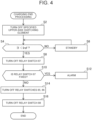
- the control circuit 90 executes the charging end processing shown in FIG. 4 in accordance with a charging end program when the charging operation is ended.
- the charging end processing is executed when the first battery 11 and the second battery 12 are fully charged or a predetermined amount of time elapses from the start of the charging operation.
- Step S2 the control circuit 90 turns OFF the specified upper-side switching element. As a result, a state in which all of the reverse conducting switching elements are turned OFF is obtained. When all of the reverse conducting switching elements are turned OFF, the application of the charging equipment supplying voltage to the second battery 12 is stopped. In this phase, as shown in FIG. 1 , the charging equipment supplying voltage is applied to the first battery 11.
- a leakage current I1 flows from the second battery 12 to the first battery 11 as shown in FIG. 5 when voltage V2 across both ends of the second battery 12 is higher than voltage V1 across both ends of the first battery 11 in a state in which all of the reverse conducting switching elements are turned OFF.
- the leakage current I1 flows from the positive electrode of the second battery 12 to the positive electrode of the first battery 11 via the neutral point 46, the diodes of upper-side reverse conducting switching elements 35U, 35VU, 35WU, and the high potential wire 31.
- FIG. 5 as an example, a route passing through the diode of the upper-side reverse conducting switching element 35VU is shown.
- the leakage current I1 does not flow when the voltage V2 across the second battery 12 is lower than the voltage V1 across the first battery 11.
- fixation may occur at a contact point of the relay switch 87, and the relay switch 87 may not be able to be turned OFF.
- Step S4 the control circuit 90 detects the leakage current I1 by the ammeter 20 or 52 and determines whether the leakage current I1 is smaller than a reference value Iref.
- the reference value Iref is a current at a level at which the fixation of the relay switch does not occur and is a value at which the leakage current I1 can be considered to be zero.
- the control circuit 90 stands by for a predetermined amount of time in Step S6.
- the control circuit 90 repeats Steps S4, S6 until the leakage current I1 becomes smaller than the reference value Iref.
- the leakage current I1 flows and the voltage V2 across the second battery 12 decreases.
- Step S10 the control circuit 90 executes fixation determination processing of the relay switch 87.
- the control circuit 90 switches at least one of the upper-side reverse conducting switching elements 35UU, 35VU, 35WU, and monitors a current value detected by the ammeter 52.
- the relay switch 87 is suitably turned OFF, the current value does not change in the fixation determination processing.
- the relay switch 87 has not been able to be turned OFF by fixation, the current value changes when the upper-side reverse conducting switching element is switched.
- the control circuit 90 detects the fixation of the relay switch 87, the control circuit 90 causes the vehicle or the charging equipment to display an alarm in Step S12.
- control circuit 90 When the control circuit 90 does not detect the fixation of the relay switch 87 in Step S10, the control circuit 90 stops the charging current supplied from the charging equipment and turns OFF the relay switches 85, 86 in Step S14. Next, the control circuit 90 turns OFF the relay switch 88 in Step S16. As a result, the charging processing ends, and it becomes possible to remove the connector of the charging equipment from the charging port 70.
- the relay switch 87 is turned OFF after the leakage current I1 is stopped, and hence the fixation of the relay switch 87 can be reduced.
- Step S6a is executed in place of Step S6 of Embodiment 1.
- Other configurations of Embodiment 2 are equivalent to those of Embodiment 1.
- Step S4 when it is determined that the leakage current I1 is equal to or more than the reference value Iref in Step S4, the control circuit 90 increases the supply current of the charging equipment (in other words, current supplied from the external charging equipment by the route indicated by the arrow 100 in FIG. 1 ) in Step S6a.
- the control circuit 90 repeats Steps S4, S6a until the leakage current I1 becomes smaller than the reference value Iref, and the control circuit 90 turns OFF the relay switch 87 in Step S8 when the leakage current I1 becomes smaller than the reference value Iref.
- the fixation of the relay switch 87 can be prevented.
- the leakage current I1 is decreased by increasing the supply current of the charging equipment. According to this configuration, the leakage current I1 can be decreased by an amount of time shorter than that in Embodiment 1. Therefore, the charging end processing can be completed by a shorter amount of time.
- the control circuit 90 repeatedly executes Step S26 during the charging of the first battery 11.
- Step S28 When the voltage V1 becomes higher than the voltage V2 by the charging of the first battery, the control circuit 90 executes Step S28.
Landscapes
- Engineering & Computer Science (AREA)
- Power Engineering (AREA)
- Transportation (AREA)
- Mechanical Engineering (AREA)
- Life Sciences & Earth Sciences (AREA)
- Sustainable Development (AREA)
- Sustainable Energy (AREA)
- Physics & Mathematics (AREA)
- General Physics & Mathematics (AREA)
- Charge And Discharge Circuits For Batteries Or The Like (AREA)
- Electric Propulsion And Braking For Vehicles (AREA)
- Control Of Electric Motors In General (AREA)
Abstract
An electric circuit (10) mounted on a vehicle includes: a first battery (11); a second battery (12); a three-phase motor (40); an inverter circuit (30); a charging port (70); a first relay switch (86); a second relay switch (85); a third relay switch (87); and a control circuit (90). The first relay switch (86) is provided between a high potential wire (31) and a high potential charging terminal. The second relay switch (85) is provided between a low potential wire (32) and a low potential charging terminal. The third relay switch (87) is provided between a positive electrode of the second battery (12) and a neutral point (46). The control circuit (90) is configured to turn OFF the third relay switch (87) and then turn OFF the first relay switch (86) and the second relay switch (85) when a charging operation is to be ended.
Description
- The present disclosure relates to an electric circuit and a non-transitory storage medium.
-
Japanese Unexamined Patent Application Publication No. 2020-120566 - There is a technology of charging each battery in an electric circuit having two batteries, an inverter circuit, and a three-phase motor with use of charging equipment outside a vehicle. One battery is connected to the charging equipment via a wire. The other battery is connected to the charging equipment via the inverter circuit and the three-phase motor. According to this configuration, the two batteries can be charged in parallel. This type of electric circuit has a relay switch, and the relay switch is turned OFF when the charging processing ends. The present disclosure discloses an electric circuit and a non-transitory storage medium that reduce deterioration of the relay switch.
- An electric circuit according to a first aspect of the present disclosure is mounted on a vehicle. The electric circuit includes: a first battery; a second battery; a three-phase motor; an inverter circuit; a charging port; a first relay switch; a second relay switch; a third relay switch; and a control circuit. The three-phase motor has three windings that are a U-phase winding, a V-phase winding, and a W-phase winding. The three windings each have a first connection terminal provided on one end of the winding and a second connection terminal provided on another end of the winding. The second connection terminals of the three windings are connected to each other at a neutral point. The inverter circuit is connected to the first connection terminal of the U-phase winding, the first connection terminal of the V-phase winding, and the first connection terminal of the W-phase winding and has a high potential wire, a low potential wire, and three series switch circuits respectively provided for the three windings. The three series switch circuits each have an upper-side reverse conducting switching element that is a reverse conducting switching element connected between the high potential wire and the first connection terminal of the corresponding winding, and a lower-side reverse conducting switching element that is a reverse conducting switching element connected between the low potential wire and the first connection terminal of the corresponding winding. The charging port has a high potential charging terminal and a low potential charging terminal and is connected to charging equipment outside the vehicle. The first relay switch is provided between the high potential wire and the high potential charging terminal. The second relay switch is provided between the low potential wire and the low potential charging terminal. The third relay switch is provided between a positive electrode of the second battery and the neutral point. The control circuit is configured to execute a charging operation of controlling the first relay switch, the second relay switch, and the third relay switch to be turned ON, controlling the three lower-side reverse conducting switching elements to be turned OFF, and continuously or intermittently turning ON a specified upper-side reverse conducting switching element that is at least one of the three upper-side reverse conducting switching elements in a state in which the high potential wire is connected to a positive electrode of the first battery and the low potential wire is connected to a negative electrode of the first battery and a negative electrode of the second battery when the first battery and the second battery are charged by the charging port. The control circuit is configured to turn OFF the third relay switch and then turn OFF the first relay switch and the second relay switch when the charging operation is to be ended.
- In the electric circuit according to the first aspect of the present disclosure, the control circuit may be configured to turn OFF the specified upper-side reverse conducting switching element and then turn OFF the third relay switch when the charging operation is to be ended.
- In the electric circuit according to the first aspect of the present disclosure, the control circuit may be configured to detect a leakage current that flows from the positive electrode of the second battery to the positive electrode of the first battery via the neutral point after the specified upper-side reverse conducting switching element is turned OFF and to turn OFF the third relay switch when the leakage current is smaller than a reference value.
- In the electric circuit according to the first aspect of the present disclosure, the control circuit may be configured to raise a current supplied from the charging equipment outside the vehicle to the charging port until a leakage current that flows from the positive electrode of the second battery to the positive electrode of the first battery via the neutral point becomes smaller than a reference value after the specified upper-side reverse conducting switching element is turned OFF, and to turn OFF the third relay switch when the leakage current is smaller than the reference value.
- In the electric circuit according to the first aspect of the present disclosure, the control circuit may be configured to execute fixation determination processing of detecting a current that flows to the second battery in a state in which the specified upper-side reverse conducting switching element is turned ON and a state in which the specified upper-side reverse conducting switching element is turned OFF after a signal that turns OFF the third relay switch is output.
- A non-transitory storage medium according to the second aspect of the present disclosure stores instructions that are executable by one or more processors and causes the one or more processors to perform functions below. The functions include causing an electric circuit mounted on a vehicle to execute charging processing. The electric circuit includes: a first battery; a second battery; a three-phase motor; an inverter circuit; a charging port; a first relay switch; a second relay switch; a third relay switch; and a control circuit. The three-phase motor has three windings that are a U-phase winding, a V-phase winding, and a W-phase winding. The three windings each have a first connection terminal provided on one end of the winding and a second connection terminal provided on another end of the winding. The second connection terminals of the three windings are connected to each other at a neutral point. The inverter circuit is connected to the first connection terminal of the U-phase winding, the first connection terminal of the V-phase winding, and the first connection terminal of the W-phase winding and has a high potential wire, a low potential wire, and three series switch circuits respectively provided for the three windings. The series switch circuits each have an upper-side reverse conducting switching element that is a reverse conducting switching element connected between the high potential wire and the first connection terminal of the corresponding winding, and a lower-side reverse conducting switching element that is a reverse conducting switching element connected between the low potential wire and the first connection terminal of the corresponding winding. The charging port has a high potential charging terminal and a low potential charging terminal and is connected to charging equipment outside the vehicle. The first relay switch is provided between the high potential wire and the high potential charging terminal. The second relay switch is provided between the low potential wire and the low potential charging terminal. The third relay switch is provided between a positive electrode of the second battery and the neutral point. The functions include causing the control circuit to execute a charging operation. The charging operation is an operation of controlling the first relay switch, the second relay switch, and the third relay switch to be turned ON, controlling the three lower-side reverse conducting switching elements to be turned OFF, and continuously or intermittently turning ON a specified upper-side reverse conducting switching element that is at least one of the three upper-side reverse conducting switching elements in a state in which the high potential wire is connected to a positive electrode of the first battery and the low potential wire is connected to a negative electrode of the first battery and a negative electrode of the second battery when the first battery and the second battery are charged by the charging port. The functions include causing the control circuit to turn OFF the third relay switch and then to turn OFF the first relay switch and the second relay switch when the charging operation is to be ended.
- In the present specification, the reverse conducting switching element means an element in which a switching element and a diode are connected in parallel to each other and an element in which a cathode of the diode is connected to a high-potential-side terminal of the switching element and an anode of the diode is connected to a low-potential-side terminal of the switching element. The switching element may be a semiconductor switching element such as a field effect transistor and an insulated gate bipolar transistor. The diode may be a pn diode or a Schottky barrier diode. The switching element and the diode may be provided on a common semiconductor substrate or may be provided on different semiconductor substrates. In the present specification, turning ON of the reverse conducting switching element means turning ON of the switching element included in the reverse conducting switching element, and turning OFF of the reverse conducting switching element means turning OFF of the switching element included in the reverse conducting switching element.
- The electric circuit of the present disclosure turns OFF the third relay switch and then turns OFF the first relay switch and the second relay switch when the charging operation is to be ended. According to this configuration, it becomes possible to reduce the deterioration of the first relay switch and the second relay switch.
- Features, advantages, and technical and industrial significance of exemplary embodiments of the invention will be described below with reference to the accompanying drawings, in which like signs denote like elements, and wherein:
-
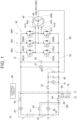
FIG. 1 is a circuit diagram of an electric circuit of an embodiment and is a diagram showing a charging route for a first battery; -
FIG. 2 is a circuit diagram of the electric circuit of the embodiment and is a diagram showing a charging route for a second battery in a state in which an upper-side reverse conducting switching element is turned ON; -
FIG. 3 is a circuit diagram of the electric circuit of the embodiment and is a diagram showing a charging route for the second battery in a state in which the upper-side reverse conducting switching element is turned OFF; -
FIG. 4 is a flowchart showing charging end processing ofEmbodiment 1; -
FIG. 5 is a circuit diagram of the electric circuit of the embodiment and is a diagram showing a route of aleakage current 11; -
FIG. 6 is a flowchart showing charging end processing ofEmbodiment 2; and -
FIG. 7 is a flowchart showing charging end processing ofEmbodiment 3. - In first electric circuit, in one example, the control circuit may turn OFF the specified upper-side reverse conducting switching element and then turn OFF the third relay switch when the charging operation is to be ended.
- According to this configuration, the deterioration of the third relay switch can be reduced.
- In the first electric circuit, in one example, the control circuit may detect a leakage current that flows from the positive electrode of the second battery to the positive electrode of the first battery via the neutral point after the specified upper-side reverse conducting switching element is turned OFF and turn OFF the third relay switch when the leakage current is smaller than a reference value.
- According to this configuration, the deterioration of the third relay switch can be reduced more effectively.
- In the first electric circuit, in one example, the control circuit may raise a current supply to the charging port until a leakage current that flows from the positive electrode of the second battery to the positive electrode of the first battery via the neutral point becomes smaller than a reference value after the specified upper-side reverse conducting switching element is turned OFF, and turn OFF the third relay switch when the leakage current is smaller than the reference value.
- According to this configuration, the deterioration of the third relay switch can be reduced more effectively.
- In the first electric circuit, in one example, the control circuit may execute fixation determination processing of detecting a current that flows to the second battery in a state in which the specified upper-side reverse conducting switching element is turned ON and a state in which the specified upper-side reverse conducting switching element is turned OFF after a signal that turns OFF the third relay switch is output.
- According to this configuration, fixation of the third relay switch can be detected.
- A second electric circuit disclosed in the present specification is mounted on a vehicle. The electric circuit has: a first battery; a second battery; a three-phase motor; an inverter circuit; a charging port; a first relay switch; a second relay switch; a third relay switch; and a control circuit. The three-phase motor has three windings that are a U-phase winding, a V-phase winding, and a W-phase winding. The three windings each have a first connection terminal provided on one end of the winding and a second connection terminal provided on another end of the winding. The second connection terminals of the three windings are connected to each other at a neutral point. The inverter circuit is connected to the first connection terminal of the U-phase winding, the first connection terminal of the V-phase winding, and the first connection terminal of the W-phase winding. The charging port has a high potential charging terminal and a low potential charging terminal and is connected to charging equipment outside the vehicle. The inverter circuit has a high potential wire, a low potential wire, and three series switch circuits respectively provided for the three windings. The series switch circuits each have an upper-side reverse conducting switching element that is a reverse conducting switching element connected between the high potential wire and the first connection terminal of the corresponding winding, and a lower-side reverse conducting switching element that is a reverse conducting switching element connected between the low potential wire and the first connection terminal of the corresponding winding. The first relay switch is provided between the high potential wire and the high potential charging terminal. The second relay switch is provided between the low potential wire and the low potential charging terminal. The third relay switch is provided between a positive electrode of the second battery and the neutral point. The control circuit can execute a charging operation of controlling the first relay switch, the second relay switch, and the third relay switch to be turned ON, controlling the three lower-side reverse conducting switching elements to be turned OFF, and continuously or intermittently turning ON a specified upper-side reverse conducting switching element that is at least one of the three upper-side reverse conducting switching elements in a state in which the high potential wire is connected to a positive electrode of the first battery and the low potential wire is connected to a negative electrode of the first battery and a negative electrode of the second battery when the first battery and the second battery are charged by the charging port. The control circuit turns OFF the specified upper-side reverse conducting switching element, then charges the first battery until OCV across the first battery becomes higher than OCV across the second battery, and then turns OFF the third relay switch when the charging operation is to be ended.
- The second electric circuit turns OFF the specified upper-side reverse conducting switching element, then charges the first battery until OCV across the first battery becomes higher than OCV across the second battery, and then turns OFF the third relay switch when the charging operation is to be ended. According to this configuration, the deterioration of the third relay switch can be reduced.
- An
electric circuit 10 shown inFIG. 1 is mounted on a vehicle. Theelectric circuit 10 has afirst battery 11, asecond battery 12, aninverter circuit 30, and a three-phase motor 40. The three-phase motor 40 is a traveling motor of the vehicle. Theinverter circuit 30 converts DC electricity supplied from thefirst battery 11 and thesecond battery 12 to AC electricity and supplies the AC electricity to the three-phase motor 40. As a result, the three-phase motor 40 rotates driving wheels, and the vehicle travels. - The three-
phase motor 40 has a U-phase winding 44U, a V-phase winding 44V, and a W-phase winding 44W. A terminal 41U and a terminal 42U are provided on both ends of the winding 44U. A terminal 41V and a terminal 42V are provided on both ends of the winding 44V. A terminal 41W and a terminal 42W are provided on both ends of the winding 44W. Theterminals neutral point 46. - The
inverter circuit 30 is connected to theterminals phase motor 40. Theinverter circuit 30 has a highpotential wire 31, a lowpotential wire 32, and three series switchcircuits series switch circuits potential wire 31 and the lowpotential wire 32. Out of the two reverse conducting switching elements 35 connected in series, the reverse conducting switching element connected to the highpotential wire 31 may be referred to as an upper-side reverse conducting switching element, and the reverse conducting switching element connected to the lowpotential wire 32 may be referred to as a lower-side reverse conducting switching element below. Each of the reverse conducting switching elements 35 has a structure in which a switching element (for example, an insulated gate bipolar transistor or a field effect transistor) and a diode (for example, a pn diode or a Schottky barrier diode) are connected in inverse-parallel with each other. In each of the reverse conducting switching elements 35, a cathode of the diode is connected to a high potential terminal (in other words, a collector or a drain) of the switching element, and an anode of the diode is connected to a low potential terminal (in other words, an emitter or a source) of the switching element. - The
series switch circuit 34U is provided with respect to the winding 44U. Theseries switch circuit 34U has an upper-side reverse conducting switching element 35UU and a lower-side reverse conducting switching element 35UL. A high potential terminal of the upper-side reverse conducting switching element 35UU is connected to the highpotential wire 31. A low potential terminal of the upper-side reverse conducting switching element 35UU and a high potential terminal of the lower-side reverse conductingswitching element 3 5UL are connected to the terminal 41U. A low potential terminal of the lower-side reverse conducting switching element 35UL is connected to the lowpotential wire 32. - The
series switch circuit 34V is provided with respect to the winding 44V. Theseries switch circuit 34V has an upper-side reverse conducting switching element 35VU and a lower-side reverse conducting switching element 35VL. A high potential terminal of the upper-side reverse conducting switching element 35VU is connected to the highpotential wire 31. A low potential terminal of the upper-side reverse conducting switching element 35VU and a high potential terminal of the lower-side reverse conducting switching element 35VL are connected to theterminal 41V. A low potential terminal of the lower-side reverse conducting switching element 35VL is connected to the lowpotential wire 32. - The
series switch circuit 34W is provided with respect to the winding 44W. Theseries switch circuit 34W has an upper-side reverse conducting switching element 35WU and a lower-side reverse conducting switching element 35WL. A high potential terminal of the upper-side reverse conducting switching element 35WU is connected to the highpotential wire 31. A low potential terminal of the upper-side reverse conducting switching element 35WU and a high potential terminal of the lower-side reverse conducting switching element 35WL are connected to the terminal 41W. A low potential terminal of the lower-side reverse conducting switching element 35WL is connected to the lowpotential wire 32. - A
capacitor 36 is connected between the highpotential wire 31 and the lowpotential wire 32. Avoltmeter 37 is connected between the highpotential wire 31 and the lowpotential wire 32. - A
neutral point wire 50 is connected to theneutral point 46 of the three-phase motor 40. Thecapacitor 60 is connected between theneutral point wire 50 and the lowpotential wire 32. Avoltmeter 61 is connected between theneutral point wire 50 and the lowpotential wire 32. - The
electric circuit 10 has a chargingport 70. A connector of charging equipment outside the vehicle can be connected to the chargingport 70. The chargingport 70 has a highpotential charging terminal 71 and a lowpotential charging terminal 72. When the connector of the charging equipment is connected to the chargingport 70, DC voltage is applied to a place between the highpotential charging terminal 71 and the lowpotential charging terminal 72 by the charging equipment in a direction in which the highpotential charging terminal 71 becomes a high potential. - The
electric circuit 10 has a plurality of relay switches 81 to 88. When each relay switch is switched, a mutual connection relationship between thefirst battery 11, thesecond battery 12, the highpotential wire 31, the lowpotential wire 32, theneutral point 46, and the chargingport 70 is changed. - The
relay switch 81 is provided between a negative electrode of thefirst battery 11 and a positive electrode of thesecond battery 12. When therelay switch 81 is turned ON, thefirst battery 11 and thesecond battery 12 are connected to each other in series. - The
relay switch 82 is provided between the negative electrode of thefirst battery 11 and a negative electrode of thesecond battery 12. When therelay switch 82 is turned ON, the negative electrode of thefirst battery 11 and the negative electrode of thesecond battery 12 are connected to each other. - An
ammeter 20 and arelay switch 83 are provided in series between a positive electrode of thefirst battery 11 and the highpotential wire 31. When therelay switch 83 is turned ON, the positive electrode of thefirst battery 11 is connected to the highpotential wire 31. - The
relay switch 84 is provided between the negative electrode of thesecond battery 12 and the lowpotential wire 32. When therelay switch 84 is turned ON, the negative electrode of thesecond battery 12 connected to the lowpotential wire 32. - The
relay switch 85 is provided between the lowpotential charging terminal 72 and the lowpotential wire 32. When therelay switch 85 is turned ON, the lowpotential charging terminal 72 is connected to the lowpotential wire 32. - The
relay switch 86 is provided between the highpotential charging terminal 71 and the highpotential wire 31. When therelay switch 86 is turned ON, the highpotential charging terminal 71 is connected to the highpotential wire 31. - An
ammeter 52 and arelay switch 87 are provided in series between the positive electrode of thesecond battery 12 and theneutral point wire 50. Therelay switch 88 is provided in theneutral point wire 50. When the relay switches 87, 88 are turned ON, the positive electrode of thesecond battery 12 is connected to theneutral point 46. - The
electric circuit 10 has acontrol circuit 90. Thecontrol circuit 90 is configured by a CPU, a memory, and the like. A program that controls theelectric circuit 10 is stored in the memory of thecontrol circuit 90. Thecontrol circuit 90 controls the switching element of each reverse conducting switching element 35 and the relay switches 81 to 88 in accordance with the program. Thecontrol circuit 90 can execute a normal operation and a charging operation. - In the normal operation, the
control circuit 90 turns ON the relay switches 81, 83, 84 and turns OFF the relay switches 82, 85, 86, 87, 88. In this state, thefirst battery 11 and thesecond battery 12 are connected in series between the highpotential wire 31 and the lowpotential wire 32. Therefore, DC voltage output by the series circuit of thefirst battery 11 and thesecond battery 12 is applied to a place between the highpotential wire 31 and the lowpotential wire 32. Thecontrol circuit 90 converts the DC electricity applied to a place between the highpotential wire 31 and the lowpotential wire 32 to AC electricity and supplies the AC electricity to the three-phase motor 40 by switching the switching element of each reverse conducting switching element 35. As a result, the three-phase motor 40 rotates. Thecontrol circuit 90 controls the torque and the rotation speed of the three-phase motor 40 by changing the amplitude, the frequency, and the like of the AC supplied to the three-phase motor 40. - In the charging operation, the
control circuit 90 performs charging of thefirst battery 11 and thesecond battery 12 by executing a charging program. When the connector of the external charging equipment is connected to the chargingport 70, thecontrol circuit 90 starts the charging operation. In the charging operation, thecontrol circuit 90 turns ON the relay switches 82, 83, 84, 85, 86, 87, 88 and turns OFF therelay switch 81. In the charging operation, thefirst battery 11 and thesecond battery 12 are charged in parallel. - An
arrow 100 inFIG. 1 indicates a charging route for thefirst battery 11. In the charging operation, the positive electrode of thefirst battery 11 is connected to the highpotential charging terminal 71 via the relay switches 83, 86, and the negative electrode of thefirst battery 11 is connected to the lowpotential charging terminal 72 via the relay switches 82, 84, 85. Therefore, voltage (hereinafter referred to as charging equipment supplying voltage) supplied from the external charging equipment is applied to thefirst battery 11, and charging current flows to thefirst battery 11 by the route shown by thearrow 100 inFIG. 1 . As a result, thefirst battery 11 is charged. - In the charging operation, the high
potential wire 31 is connected to the highpotential charging terminal 71 via therelay switch 86, and the lowpotential wire 32 is connected to the lowpotential charging terminal 72 via therelay switch 85. The positive electrode of thesecond battery 12 is connected to theneutral point 46 via the relay switches 87, 88, and the negative electrode of thesecond battery 12 is connected to the lowpotential charging terminal 72 and the lowpotential wire 32 via the relay switches 84, 85. In the charging operation, thecontrol circuit 90 turns OFF lower-side reverse conducting switching elements 35UL, 35VL, and 35WL. In a state in which each unit is controlled as above, thecontrol circuit 90 executes the charging of thesecond battery 12 by controlling at least one (hereinafter referred to as a specified upper-side switching element) of the upper-side reverse conducting switching elements 35UU, 35VU, 35WU. When elements other than the specified upper-side switching element out of the upper-side reverse conducting switching elements 35UU, 35VU, 35WU are present, thecontrol circuit 90 maintains the elements other than the specified upper-side switching element to be turned OFF. - In the charging operation, the
control circuit 90 can execute a direct charging operation and a step-down charging operation for thesecond battery 12. - In the direct charging operation, the
control circuit 90 maintains the specified upper-side switching element to be turned ON (in other words, turns the specified upper-side switching element to be continuously ON). Anarrow 102 inFIG. 2 indicates a current route when the upper-side reverse conducting switching element 35VU is turned ON as the specified upper-side switching element. When the upper-side reverse conducting switching element 35VU is turned ON, the positive electrode of thesecond battery 12 is connected to the highpotential charging terminal 71 via the relay switches 87, 88, theneutral point 46, the winding 44V, the upper-side reverse conducting switching element 35VU, the highpotential wire 31, and therelay switch 86. Therefore, the charging equipment supplying voltage is applied to thesecond battery 12. As a result, the charging current flows by the route indicated by thearrow 102, and thesecond battery 12 is charged. - In the step-down charging operation, the
control circuit 90 periodically switches the specified upper-side switching element (in other words, intermittently turns the specified upper-side switching element ON). Thearrows FIGS. 2 ,3 exemplify the current routes when the upper-side reverse conducting switching element 35VU is the specified upper-side switching element as the current route of the step-down charging operation. When the upper-side reverse conducting switching element 35VU is turned ON, the charging current flows as indicated by thearrow 102 inFIG. 2 . When the upper-side reverse conducting switching element 35VU is turned OFF thereafter, induced electromotive voltage is generated in the winding 44V. As a result, as indicated by thearrow 104 inFIG. 3 , a return current flows via a diode of the lower-side reverse conducting switching element 35VL, the winding 44V, and thesecond battery 12. In the step-down charging operation, thesecond battery 12 is charged as a result of the current alternately flowing through the routes indicated by thearrows inverter circuit 30 and the winding of the three-phase motor 40 function as a step-down converter circuit. Therefore, voltage lower than the charging equipment supplying voltage is applied to thesecond battery 12, and thesecond battery 12 is charged by a low charging current. - As described above, in the charging operation, the
first battery 11 is charged by the route indicated by thearrow 100, and thesecond battery 12 is charged by the direct charging operation or the step-down charging operation. In other words, thefirst battery 11 and thesecond battery 12 are charged in parallel. It is also possible for thecontrol circuit 90 to be configured to execute only one of the direct charging operation and the step-down charging operation. - The
control circuit 90 executes the charging end processing shown inFIG. 4 in accordance with a charging end program when the charging operation is ended. The charging end processing is executed when thefirst battery 11 and thesecond battery 12 are fully charged or a predetermined amount of time elapses from the start of the charging operation. - In Step S2, the
control circuit 90 turns OFF the specified upper-side switching element. As a result, a state in which all of the reverse conducting switching elements are turned OFF is obtained. When all of the reverse conducting switching elements are turned OFF, the application of the charging equipment supplying voltage to thesecond battery 12 is stopped. In this phase, as shown inFIG. 1 , the charging equipment supplying voltage is applied to thefirst battery 11. - A leakage current I1 flows from the
second battery 12 to thefirst battery 11 as shown inFIG. 5 when voltage V2 across both ends of thesecond battery 12 is higher than voltage V1 across both ends of thefirst battery 11 in a state in which all of the reverse conducting switching elements are turned OFF. The leakage current I1 flows from the positive electrode of thesecond battery 12 to the positive electrode of thefirst battery 11 via theneutral point 46, the diodes of upper-side reverse conducting switching elements 35U, 35VU, 35WU, and the highpotential wire 31. InFIG. 5 , as an example, a route passing through the diode of the upper-side reverse conducting switching element 35VU is shown. Meanwhile, the leakage current I1 does not flow when the voltage V2 across thesecond battery 12 is lower than the voltage V1 across thefirst battery 11. When therelay switch 87 is to be turned OFF in a state in which the leakage current I1 is flowing, fixation may occur at a contact point of therelay switch 87, and therelay switch 87 may not be able to be turned OFF. - In Step S4, the
control circuit 90 detects the leakage current I1 by theammeter control circuit 90 stands by for a predetermined amount of time in Step S6. Thecontrol circuit 90 repeats Steps S4, S6 until the leakage current I1 becomes smaller than the reference value Iref. During the standby of thecontrol circuit 90, the leakage current I1 flows and the voltage V2 across thesecond battery 12 decreases. During the standby of thecontrol circuit 90, thefirst battery 11 is charged and the voltage V1 rises. Therefore, the leakage current I1 gradually decreases during the standby of thecontrol circuit 90. When the leakage current I1 becomes smaller than the reference value Iref, thecontrol circuit 90 determines that Step S4 is YES and outputs an OFF signal to therelay switch 87 in Step S8. As a result, therelay switch 87 is turned OFF. Therelay switch 87 can be turned OFF in a state in which the leakage current I1 is low, and hence the fixation of therelay switch 87 can be reduced. - Next, in Step S10, the
control circuit 90 executes fixation determination processing of therelay switch 87. In the fixation determination processing, thecontrol circuit 90 switches at least one of the upper-side reverse conducting switching elements 35UU, 35VU, 35WU, and monitors a current value detected by theammeter 52. When therelay switch 87 is suitably turned OFF, the current value does not change in the fixation determination processing. Meanwhile, when therelay switch 87 has not been able to be turned OFF by fixation, the current value changes when the upper-side reverse conducting switching element is switched. When thecontrol circuit 90 detects the fixation of therelay switch 87, thecontrol circuit 90 causes the vehicle or the charging equipment to display an alarm in Step S12. - When the
control circuit 90 does not detect the fixation of therelay switch 87 in Step S10, thecontrol circuit 90 stops the charging current supplied from the charging equipment and turns OFF the relay switches 85, 86 in Step S14. Next, thecontrol circuit 90 turns OFF therelay switch 88 in Step S16. As a result, the charging processing ends, and it becomes possible to remove the connector of the charging equipment from the chargingport 70. - As described above, in
Embodiment 1, therelay switch 87 is turned OFF after the leakage current I1 is stopped, and hence the fixation of therelay switch 87 can be reduced. - As shown in
FIG. 6 , in an electric circuit ofEmbodiment 2, Step S6a is executed in place of Step S6 ofEmbodiment 1. Other configurations ofEmbodiment 2 are equivalent to those ofEmbodiment 1. - In
Embodiment 2, when it is determined that the leakage current I1 is equal to or more than the reference value Iref in Step S4, thecontrol circuit 90 increases the supply current of the charging equipment (in other words, current supplied from the external charging equipment by the route indicated by thearrow 100 inFIG. 1 ) in Step S6a. When the supply current of the charging equipment increases, the potential of the highpotential wire 31 rises, and the leakage current I1 decreases. Thecontrol circuit 90 repeats Steps S4, S6a until the leakage current I1 becomes smaller than the reference value Iref, and thecontrol circuit 90 turns OFF therelay switch 87 in Step S8 when the leakage current I1 becomes smaller than the reference value Iref. As a result, the fixation of therelay switch 87 can be prevented. - As described above, in
Embodiment 2, the leakage current I1 is decreased by increasing the supply current of the charging equipment. According to this configuration, the leakage current I1 can be decreased by an amount of time shorter than that inEmbodiment 1. Therefore, the charging end processing can be completed by a shorter amount of time. - An electric circuit of
Embodiment 3 executes charging end processing shown inFIG. 7 . Other configurations ofEmbodiment 3 are equivalent to those ofEmbodiment 1. - In Step S22 the
control circuit 90 turns OFF the specified upper-side switching element. As a result, a state in which all of the reverse conducting switching elements are turned OFF is obtained. When all of the reverse conducting switching elements are turned OFF, the application of the charging equipment supplying voltage to thesecond battery 12 is stopped. In this phase, the charging equipment supplying voltage is applied to thefirst battery 11. - Next, in Step S24, the
control circuit 90 decreases the supply current of the charging equipment (in other words, the current supplied from the external charging equipment by the route indicated by thearrow 100 inFIG. 1 ) by giving a command to the external charging equipment. As a result, the charging current with respect to thefirst battery 11 decreases. - After the execution of Steps S22, S24, the
control circuit 90 determines whether the voltage V1 across both ends of the first battery 11 (in other words, closed circuit voltage (CCV) across the first battery 11) is higher than the voltage V2 across both ends of the second battery 12 (in other words, open circuit voltage (OCV) across the second battery 12) in Step S26. When the voltage V2 is higher than the voltage V1, the leakage current I1 flows as shown inFIG. 5 . The supply current of the charging equipment is decreased, and hence the CCV is substantially equal to the OCV in thefirst battery 11. Therefore, the determination in Step S26 is equivalent to determining whether the OCV across the first battery is higher than the OCV across the second battery. The voltage V2 can be detected by thevoltmeter 61. The voltage V1 can be detected by subtracting the detection value of thevoltmeter 61 from the detection value of thevoltmeter 37. Thecontrol circuit 90 can detect the voltage V1, V2 and execute the determination in Step S26 on the basis of those detection values. As described above, the leakage current I1 flows when the voltage V2 is higher than the voltage V1. Therefore, thecontrol circuit 90 may execute the determination in Step S26 by determining whether the leakage current I1 is flowing. - The
control circuit 90 repeatedly executes Step S26 during the charging of thefirst battery 11. When the voltage V1 becomes higher than the voltage V2 by the charging of the first battery, thecontrol circuit 90 executes Step S28. - In Step S28, the
control circuit 90 turns OFF the relay switches 85, 86. As a result, the charging of thefirst battery 11 ends. As described above, thefirst battery 11 is charged to a state in which the OCV across thefirst battery 11 is higher than the OCV across the second battery, and hence the state in which the voltage V1 is higher than the voltage V2 is maintained even after the relay switches 85, 86 are turned OFF. Therefore, the leakage current I1 does not flow in Step S28 and thereafter either. - In Step S30, the
control circuit 90 turns OFF therelay switch 87. The leakage current I1 is not flowing, and hence the fixation of therelay switch 87 can be prevented when therelay switch 87 is turned OFF. - In Step S32, the
control circuit 90 executes the fixation determination processing of therelay switch 87 as with Step S10 inFIG. 4 . When thecontrol circuit 90 detects the fixation of therelay switch 87, thecontrol circuit 90 causes the vehicle or the charging equipment to display an alarm in Step S34. When therelay switch 87 is not fixed, thecontrol circuit 90 turns OFF therelay switch 88 in Step S36 and completes the charging end processing. As a result, it becomes possible to remove the connector of the charging equipment from the chargingport 70. - As described above, in
Embodiment 3, the charging of thefirst battery 11 is performed such that the OCV across thefirst battery 11 becomes higher than the OCV across thesecond battery 12. Therefore, therelay switch 87 can be turned OFF in a state in which the leakage current I1 is not flowing, and the fixation of therelay switch 87 can be prevented. - In
Embodiment 3, therelay switch 87 may be turned OFF before the relay switches 85, 86. - The embodiments have been described in detail above, but those are merely exemplifications and do not limit the scope of claims. The technology described in the scope of claims includes those obtained by variously modifying and changing the specific examples exemplified above. The technical elements described in the present specification or the drawings exhibit a technical utility by itself or various combinations, and are not limited to the combinations described in the claims as originally filed. The technology exemplified in the present specification or the drawings achieves a plurality of objects at the same time, and has a technical utility by achievement of one of those objects itself.
Claims (6)
- An electric circuit (10) mounted on a vehicle, the electric circuit (10) comprising:a first battery (11);a second battery (12);a three-phase motor (40) having three windings that are a U-phase winding, a V-phase winding, and a W-phase winding, the three windings each having a first connection terminal provided on one end of the winding and a second connection terminal provided on another end of the winding, the second connection terminals of the three windings being connected to each other at a neutral point (46);an inverter circuit (30) connected to the first connection terminal of the U-phase winding, the first connection terminal of the V-phase winding, and the first connection terminal of the W-phase winding and having a high potential wire (31), a low potential wire (32), and three series switch circuits respectively provided for the three windings, the three series switch circuits each having an upper-side reverse conducting switching element that is a reverse conducting switching element connected between the high potential wire (31) and the first connection terminal of the corresponding winding, and a lower-side reverse conducting switching element that is a reverse conducting switching element connected between the low potential wire (32) and the first connection terminal of the corresponding winding;a charging port (70) having a high potential charging terminal and a low potential charging terminal and connected to charging equipment outside the vehicle;a first relay switch (86) provided between the high potential wire (31) and the high potential charging terminal;a second relay switch (85) provided between the low potential wire (32) and the low potential charging terminal;a third relay switch (87) provided between a positive electrode of the second battery (12) and the neutral point (46); anda control circuit (90) configured to:execute a charging operation of controlling the first relay switch (86), the second relay switch (85), and the third relay switch (87) to be turned ON, controlling the three lower-side reverse conducting switching elements to be turned OFF, and continuously or intermittently turning ON a specified upper-side reverse conducting switching element that is at least one of the three upper-side reverse conducting switching elements in a state in which the high potential wire (31) is connected to a positive electrode of the first battery (11) and the low potential wire (32) is connected to a negative electrode of the first battery (11) and a negative electrode of the second battery (12) when the first battery (11) and the second battery (12) are charged by the charging port (70); andturn OFF the third relay switch (87) and then turn OFF the first relay switch (86) and the second relay switch (85) when the charging operation is to be ended.
- The electric circuit (10) according to claim 1, wherein the control circuit (90) is configured to turn OFF the specified upper-side reverse conducting switching element and then turn OFF the third relay switch (87) when the charging operation is to be ended.
- The electric circuit (10) according to claim 2, wherein the control circuit (90) is configured to detect a leakage current that flows from the positive electrode of the second battery (12) to the positive electrode of the first battery (11) via the neutral point (46) after the specified upper-side reverse conducting switching element is turned OFF and to turn OFF the third relay switch (87) when the leakage current is smaller than a reference value.
- The electric circuit (10) according to claim 2, wherein the control circuit (90) is configured to raise a current supplied from the charging equipment outside the vehicle to the charging port (70) until a leakage current that flows from the positive electrode of the second battery (12) to the positive electrode of the first battery (11) via the neutral point (46) becomes smaller than a reference value after the specified upper-side reverse conducting switching element is turned OFF, and to turn OFF the third relay switch (87) when the leakage current is smaller than the reference value.
- The electric circuit (10) according to any one of claims 1 to 4, wherein the control circuit (90) is configured to execute fixation determination processing of detecting a current that flows to the second battery (12) in a state in which the specified upper-side reverse conducting switching element is turned ON and a state in which the specified upper-side reverse conducting switching element is turned OFF after a signal that turns OFF the third relay switch (87) is output.
- A non-transitory storage medium storing instructions that are executable by one or more processors and that cause the one or more processors to perform functions comprising:causing an electric circuit (10) mounted on a vehicle to execute charging processing, the electric circuit (10) having:a first battery (11);a second battery (12);a three-phase motor (40) having three windings that are a U-phase winding, a V-phase winding, and a W-phase winding, the three windings each having a first connection terminal provided on one end of the winding and a second connection terminal provided on another end of the winding, the second connection terminals of the three windings being connected to each other at a neutral point (46);an inverter circuit (30) connected to the first connection terminal of the U-phase winding, the first connection terminal of the V-phase winding, and the first connection terminal of the W-phase winding and having a high potential wire (31), a low potential wire (32), and three series switch circuits respectively provided for the three windings, the series switch circuits each having an upper-side reverse conducting switching element that is a reverse conducting switching element connected between the high potential wire (31) and the first connection terminal of the corresponding winding, and a lower-side reverse conducting switching element that is a reverse conducting switching element connected between the low potential wire (32) and the first connection terminal of the corresponding winding;a charging port (70) having a high potential charging terminal and a low potential charging terminal and connected to charging equipment outside the vehicle;a first relay switch (86) provided between the high potential wire (31) and the high potential charging terminal;a second relay switch (85) provided between the low potential wire (32) and the low potential charging terminal;a third relay switch (87) provided between a positive electrode of the second battery (12) and the neutral point (46); anda control circuit (90);causing the control circuit (90) to execute a charging operation, the charging operation being an operation of controlling the first relay switch (86), the second relay switch (85), and the third relay switch (87) to be turned ON, controlling the three lower-side reverse conducting switching elements to be turned OFF, and continuously or intermittently turning ON a specified upper-side reverse conducting switching element that is at least one of the three upper-side reverse conducting switching elements in a state in which the high potential wire (31) is connected to a positive electrode of the first battery (11) and the low potential wire (32) is connected to a negative electrode of the first battery (11) and a negative electrode of the second battery (12) when the first battery (11) and the second battery (12) are charged by the charging port (70); andcausing the control circuit (90) to turn OFF the third relay switch (87) and then to turn OFF the first relay switch (86) and the second relay switch (85) when the charging operation is to be ended.
Applications Claiming Priority (1)
| Application Number | Priority Date | Filing Date | Title |
|---|---|---|---|
| JP2023213908A JP2025097618A (en) | 2023-12-19 | 2023-12-19 | Electric circuit and program for charging treatment |
Publications (1)
| Publication Number | Publication Date |
|---|---|
| EP4578717A1 true EP4578717A1 (en) | 2025-07-02 |
Family
ID=93796685
Family Applications (1)
| Application Number | Title | Priority Date | Filing Date |
|---|---|---|---|
| EP24217074.4A Pending EP4578717A1 (en) | 2023-12-19 | 2024-12-03 | Electric circuit and non-transitory storage medium |
Country Status (5)
| Country | Link |
|---|---|
| US (1) | US20250196691A1 (en) |
| EP (1) | EP4578717A1 (en) |
| JP (1) | JP2025097618A (en) |
| KR (1) | KR20250095513A (en) |
| CN (1) | CN120171321A (en) |
Citations (3)
| Publication number | Priority date | Publication date | Assignee | Title |
|---|---|---|---|---|
| EP2062801B1 (en) * | 2007-11-22 | 2016-08-10 | Denso Corporation | Power supply system with multiphase motor and multiphase inverter |
| JP2020120566A (en) | 2019-01-24 | 2020-08-06 | 株式会社Soken | Power converter |
| US20210044135A1 (en) * | 2019-08-06 | 2021-02-11 | Hyundai Motor Company | System and method for charging using motor driving system |
-
2023
- 2023-12-19 JP JP2023213908A patent/JP2025097618A/en active Pending
-
2024
- 2024-11-22 CN CN202411679123.2A patent/CN120171321A/en active Pending
- 2024-11-26 KR KR1020240170736A patent/KR20250095513A/en active Pending
- 2024-12-03 EP EP24217074.4A patent/EP4578717A1/en active Pending
- 2024-12-06 US US18/971,374 patent/US20250196691A1/en active Pending
Patent Citations (3)
| Publication number | Priority date | Publication date | Assignee | Title |
|---|---|---|---|---|
| EP2062801B1 (en) * | 2007-11-22 | 2016-08-10 | Denso Corporation | Power supply system with multiphase motor and multiphase inverter |
| JP2020120566A (en) | 2019-01-24 | 2020-08-06 | 株式会社Soken | Power converter |
| US20210044135A1 (en) * | 2019-08-06 | 2021-02-11 | Hyundai Motor Company | System and method for charging using motor driving system |
Non-Patent Citations (1)
| Title |
|---|
| "Electric vehicle conductive charging system - Part 23: DC electric vehicle charging station", IEC 61851-23:2014, IEC, 3, RUE DE VAREMB�, PO BOX 131, CH-1211 GENEVA 20, SWITZERLAND, 11 March 2014 (2014-03-11), pages 1 - 159, XP082002294, [retrieved on 20140311] * |
Also Published As
| Publication number | Publication date |
|---|---|
| US20250196691A1 (en) | 2025-06-19 |
| CN120171321A (en) | 2025-06-20 |
| JP2025097618A (en) | 2025-07-01 |
| KR20250095513A (en) | 2025-06-26 |
Similar Documents
| Publication | Publication Date | Title |
|---|---|---|
| CN113348616B (en) | Power conversion device | |
| US6775115B2 (en) | Voltage conversion system and method and recording medium | |
| JP5954356B2 (en) | Electric vehicle | |
| US9698712B2 (en) | Inverter apparatus | |
| US9496802B2 (en) | Inverter device | |
| US20160276823A1 (en) | Power supply system | |
| JP5223367B2 (en) | Drive device | |
| US20250196653A1 (en) | Electrical circuit and storage medium | |
| US12562582B2 (en) | Power supply device charging power storage device based on voltage comparison | |
| US20250196691A1 (en) | Electric circuit and non-transitory storage medium | |
| US12549022B2 (en) | Power supply apparatus configured to detect current path abnormalities | |
| US20250183389A1 (en) | Electric circuit and storage medium | |
| JP2021035172A (en) | Controller of power converter | |
| US20250239881A1 (en) | Electrical circuit and non-transitory storage medium storing program for parallel charging start processing | |
| US20250253679A1 (en) | Power supply system | |
| US20260019022A1 (en) | Control apparatus for three-level inverter | |
| JP7758000B2 (en) | charging device | |
| US20260128604A1 (en) | Power supply system | |
| CN115122923B (en) | vehicle | |
| WO2019220484A1 (en) | Control device for ac rotary electric machine | |
| WO2026042170A1 (en) | Control device for power conversion circuit | |
| JP2025117208A (en) | Program for electrical circuits and battery heating process | |
| JP2025178854A (en) | Charging control device | |
| JP2025113586A (en) | Rotating electric machine control device, program, and rotating electric machine control method | |
| WO2024219146A1 (en) | Power conversion device |
Legal Events
| Date | Code | Title | Description |
|---|---|---|---|
| PUAI | Public reference made under article 153(3) epc to a published international application that has entered the european phase |
Free format text: ORIGINAL CODE: 0009012 |
|
| STAA | Information on the status of an ep patent application or granted ep patent |
Free format text: STATUS: REQUEST FOR EXAMINATION WAS MADE |
|
| 17P | Request for examination filed |
Effective date: 20241203 |
|
| AK | Designated contracting states |
Kind code of ref document: A1 Designated state(s): AL AT BE BG CH CY CZ DE DK EE ES FI FR GB GR HR HU IE IS IT LI LT LU LV MC ME MK MT NL NO PL PT RO RS SE SI SK SM TR |