EP4578692A1 - Method of changing cockpit layout according to display mode and cockpit system using the same - Google Patents
Method of changing cockpit layout according to display mode and cockpit system using the same Download PDFInfo
- Publication number
- EP4578692A1 EP4578692A1 EP24193270.6A EP24193270A EP4578692A1 EP 4578692 A1 EP4578692 A1 EP 4578692A1 EP 24193270 A EP24193270 A EP 24193270A EP 4578692 A1 EP4578692 A1 EP 4578692A1
- Authority
- EP
- European Patent Office
- Prior art keywords
- display
- panel
- mode
- see
- area
- Prior art date
- Legal status (The legal status is an assumption and is not a legal conclusion. Google has not performed a legal analysis and makes no representation as to the accuracy of the status listed.)
- Pending
Links
Images




Classifications
-
- B—PERFORMING OPERATIONS; TRANSPORTING
- B60—VEHICLES IN GENERAL
- B60K—ARRANGEMENT OR MOUNTING OF PROPULSION UNITS OR OF TRANSMISSIONS IN VEHICLES; ARRANGEMENT OR MOUNTING OF PLURAL DIVERSE PRIME-MOVERS IN VEHICLES; AUXILIARY DRIVES FOR VEHICLES; INSTRUMENTATION OR DASHBOARDS FOR VEHICLES; ARRANGEMENTS IN CONNECTION WITH COOLING, AIR INTAKE, GAS EXHAUST OR FUEL SUPPLY OF PROPULSION UNITS IN VEHICLES
- B60K35/00—Instruments specially adapted for vehicles; Arrangement of instruments in or on vehicles
- B60K35/20—Output arrangements, i.e. from vehicle to user, associated with vehicle functions or specially adapted therefor
- B60K35/21—Output arrangements, i.e. from vehicle to user, associated with vehicle functions or specially adapted therefor using visual output, e.g. blinking lights or matrix displays
- B60K35/22—Display screens
-
- B—PERFORMING OPERATIONS; TRANSPORTING
- B60—VEHICLES IN GENERAL
- B60K—ARRANGEMENT OR MOUNTING OF PROPULSION UNITS OR OF TRANSMISSIONS IN VEHICLES; ARRANGEMENT OR MOUNTING OF PLURAL DIVERSE PRIME-MOVERS IN VEHICLES; AUXILIARY DRIVES FOR VEHICLES; INSTRUMENTATION OR DASHBOARDS FOR VEHICLES; ARRANGEMENTS IN CONNECTION WITH COOLING, AIR INTAKE, GAS EXHAUST OR FUEL SUPPLY OF PROPULSION UNITS IN VEHICLES
- B60K35/00—Instruments specially adapted for vehicles; Arrangement of instruments in or on vehicles
- B60K35/10—Input arrangements, i.e. from user to vehicle, associated with vehicle functions or specially adapted therefor
-
- B—PERFORMING OPERATIONS; TRANSPORTING
- B60—VEHICLES IN GENERAL
- B60K—ARRANGEMENT OR MOUNTING OF PROPULSION UNITS OR OF TRANSMISSIONS IN VEHICLES; ARRANGEMENT OR MOUNTING OF PLURAL DIVERSE PRIME-MOVERS IN VEHICLES; AUXILIARY DRIVES FOR VEHICLES; INSTRUMENTATION OR DASHBOARDS FOR VEHICLES; ARRANGEMENTS IN CONNECTION WITH COOLING, AIR INTAKE, GAS EXHAUST OR FUEL SUPPLY OF PROPULSION UNITS IN VEHICLES
- B60K35/00—Instruments specially adapted for vehicles; Arrangement of instruments in or on vehicles
- B60K35/20—Output arrangements, i.e. from vehicle to user, associated with vehicle functions or specially adapted therefor
- B60K35/28—Output arrangements, i.e. from vehicle to user, associated with vehicle functions or specially adapted therefor characterised by the type of the output information, e.g. video entertainment or vehicle dynamics information; characterised by the purpose of the output information, e.g. for attracting the attention of the driver
-
- B—PERFORMING OPERATIONS; TRANSPORTING
- B60—VEHICLES IN GENERAL
- B60K—ARRANGEMENT OR MOUNTING OF PROPULSION UNITS OR OF TRANSMISSIONS IN VEHICLES; ARRANGEMENT OR MOUNTING OF PLURAL DIVERSE PRIME-MOVERS IN VEHICLES; AUXILIARY DRIVES FOR VEHICLES; INSTRUMENTATION OR DASHBOARDS FOR VEHICLES; ARRANGEMENTS IN CONNECTION WITH COOLING, AIR INTAKE, GAS EXHAUST OR FUEL SUPPLY OF PROPULSION UNITS IN VEHICLES
- B60K35/00—Instruments specially adapted for vehicles; Arrangement of instruments in or on vehicles
- B60K35/20—Output arrangements, i.e. from vehicle to user, associated with vehicle functions or specially adapted therefor
- B60K35/29—Instruments characterised by the way in which information is handled, e.g. showing information on plural displays or prioritising information according to driving conditions
-
- B—PERFORMING OPERATIONS; TRANSPORTING
- B60—VEHICLES IN GENERAL
- B60K—ARRANGEMENT OR MOUNTING OF PROPULSION UNITS OR OF TRANSMISSIONS IN VEHICLES; ARRANGEMENT OR MOUNTING OF PLURAL DIVERSE PRIME-MOVERS IN VEHICLES; AUXILIARY DRIVES FOR VEHICLES; INSTRUMENTATION OR DASHBOARDS FOR VEHICLES; ARRANGEMENTS IN CONNECTION WITH COOLING, AIR INTAKE, GAS EXHAUST OR FUEL SUPPLY OF PROPULSION UNITS IN VEHICLES
- B60K35/00—Instruments specially adapted for vehicles; Arrangement of instruments in or on vehicles
- B60K35/50—Instruments characterised by their means of attachment to or integration in the vehicle
-
- B—PERFORMING OPERATIONS; TRANSPORTING
- B60—VEHICLES IN GENERAL
- B60K—ARRANGEMENT OR MOUNTING OF PROPULSION UNITS OR OF TRANSMISSIONS IN VEHICLES; ARRANGEMENT OR MOUNTING OF PLURAL DIVERSE PRIME-MOVERS IN VEHICLES; AUXILIARY DRIVES FOR VEHICLES; INSTRUMENTATION OR DASHBOARDS FOR VEHICLES; ARRANGEMENTS IN CONNECTION WITH COOLING, AIR INTAKE, GAS EXHAUST OR FUEL SUPPLY OF PROPULSION UNITS IN VEHICLES
- B60K35/00—Instruments specially adapted for vehicles; Arrangement of instruments in or on vehicles
- B60K35/50—Instruments characterised by their means of attachment to or integration in the vehicle
- B60K35/53—Movable instruments, e.g. slidable
-
- B—PERFORMING OPERATIONS; TRANSPORTING
- B60—VEHICLES IN GENERAL
- B60K—ARRANGEMENT OR MOUNTING OF PROPULSION UNITS OR OF TRANSMISSIONS IN VEHICLES; ARRANGEMENT OR MOUNTING OF PLURAL DIVERSE PRIME-MOVERS IN VEHICLES; AUXILIARY DRIVES FOR VEHICLES; INSTRUMENTATION OR DASHBOARDS FOR VEHICLES; ARRANGEMENTS IN CONNECTION WITH COOLING, AIR INTAKE, GAS EXHAUST OR FUEL SUPPLY OF PROPULSION UNITS IN VEHICLES
- B60K35/00—Instruments specially adapted for vehicles; Arrangement of instruments in or on vehicles
- B60K35/55—Instruments with parts that can change their shape or position to configure an active screen, e.g. by folding or by rolling
-
- B—PERFORMING OPERATIONS; TRANSPORTING
- B60—VEHICLES IN GENERAL
- B60K—ARRANGEMENT OR MOUNTING OF PROPULSION UNITS OR OF TRANSMISSIONS IN VEHICLES; ARRANGEMENT OR MOUNTING OF PLURAL DIVERSE PRIME-MOVERS IN VEHICLES; AUXILIARY DRIVES FOR VEHICLES; INSTRUMENTATION OR DASHBOARDS FOR VEHICLES; ARRANGEMENTS IN CONNECTION WITH COOLING, AIR INTAKE, GAS EXHAUST OR FUEL SUPPLY OF PROPULSION UNITS IN VEHICLES
- B60K35/00—Instruments specially adapted for vehicles; Arrangement of instruments in or on vehicles
- B60K35/80—Arrangements for controlling instruments
- B60K35/81—Arrangements for controlling instruments for controlling displays
-
- G—PHYSICS
- G02—OPTICS
- G02B—OPTICAL ELEMENTS, SYSTEMS OR APPARATUS
- G02B27/00—Optical systems or apparatus not provided for by any of the groups G02B1/00 - G02B26/00, G02B30/00
- G02B27/01—Head-up displays
- G02B27/0101—Head-up displays characterised by optical features
-
- G—PHYSICS
- G02—OPTICS
- G02B—OPTICAL ELEMENTS, SYSTEMS OR APPARATUS
- G02B27/00—Optical systems or apparatus not provided for by any of the groups G02B1/00 - G02B26/00, G02B30/00
- G02B27/01—Head-up displays
- G02B27/0179—Display position adjusting means not related to the information to be displayed
-
- G—PHYSICS
- G06—COMPUTING OR CALCULATING; COUNTING
- G06F—ELECTRIC DIGITAL DATA PROCESSING
- G06F3/00—Input arrangements for transferring data to be processed into a form capable of being handled by the computer; Output arrangements for transferring data from processing unit to output unit, e.g. interface arrangements
- G06F3/14—Digital output to display device ; Cooperation and interconnection of the display device with other functional units
- G06F3/1423—Digital output to display device ; Cooperation and interconnection of the display device with other functional units controlling a plurality of local displays, e.g. CRT and flat panel display
-
- B—PERFORMING OPERATIONS; TRANSPORTING
- B60—VEHICLES IN GENERAL
- B60K—ARRANGEMENT OR MOUNTING OF PROPULSION UNITS OR OF TRANSMISSIONS IN VEHICLES; ARRANGEMENT OR MOUNTING OF PLURAL DIVERSE PRIME-MOVERS IN VEHICLES; AUXILIARY DRIVES FOR VEHICLES; INSTRUMENTATION OR DASHBOARDS FOR VEHICLES; ARRANGEMENTS IN CONNECTION WITH COOLING, AIR INTAKE, GAS EXHAUST OR FUEL SUPPLY OF PROPULSION UNITS IN VEHICLES
- B60K2360/00—Indexing scheme associated with groups B60K35/00 or B60K37/00 relating to details of instruments or dashboards
- B60K2360/128—Axially displaceable input devices for instruments
-
- B—PERFORMING OPERATIONS; TRANSPORTING
- B60—VEHICLES IN GENERAL
- B60K—ARRANGEMENT OR MOUNTING OF PROPULSION UNITS OR OF TRANSMISSIONS IN VEHICLES; ARRANGEMENT OR MOUNTING OF PLURAL DIVERSE PRIME-MOVERS IN VEHICLES; AUXILIARY DRIVES FOR VEHICLES; INSTRUMENTATION OR DASHBOARDS FOR VEHICLES; ARRANGEMENTS IN CONNECTION WITH COOLING, AIR INTAKE, GAS EXHAUST OR FUEL SUPPLY OF PROPULSION UNITS IN VEHICLES
- B60K2360/00—Indexing scheme associated with groups B60K35/00 or B60K37/00 relating to details of instruments or dashboards
- B60K2360/143—Touch sensitive instrument input devices
- B60K2360/1438—Touch screens
-
- B—PERFORMING OPERATIONS; TRANSPORTING
- B60—VEHICLES IN GENERAL
- B60K—ARRANGEMENT OR MOUNTING OF PROPULSION UNITS OR OF TRANSMISSIONS IN VEHICLES; ARRANGEMENT OR MOUNTING OF PLURAL DIVERSE PRIME-MOVERS IN VEHICLES; AUXILIARY DRIVES FOR VEHICLES; INSTRUMENTATION OR DASHBOARDS FOR VEHICLES; ARRANGEMENTS IN CONNECTION WITH COOLING, AIR INTAKE, GAS EXHAUST OR FUEL SUPPLY OF PROPULSION UNITS IN VEHICLES
- B60K2360/00—Indexing scheme associated with groups B60K35/00 or B60K37/00 relating to details of instruments or dashboards
- B60K2360/143—Touch sensitive instrument input devices
- B60K2360/1438—Touch screens
- B60K2360/1442—Emulation of input devices
-
- B—PERFORMING OPERATIONS; TRANSPORTING
- B60—VEHICLES IN GENERAL
- B60K—ARRANGEMENT OR MOUNTING OF PROPULSION UNITS OR OF TRANSMISSIONS IN VEHICLES; ARRANGEMENT OR MOUNTING OF PLURAL DIVERSE PRIME-MOVERS IN VEHICLES; AUXILIARY DRIVES FOR VEHICLES; INSTRUMENTATION OR DASHBOARDS FOR VEHICLES; ARRANGEMENTS IN CONNECTION WITH COOLING, AIR INTAKE, GAS EXHAUST OR FUEL SUPPLY OF PROPULSION UNITS IN VEHICLES
- B60K2360/00—Indexing scheme associated with groups B60K35/00 or B60K37/00 relating to details of instruments or dashboards
- B60K2360/151—Instrument output devices for configurable output
- B60K2360/1515—Reconfigurable dials
-
- B—PERFORMING OPERATIONS; TRANSPORTING
- B60—VEHICLES IN GENERAL
- B60K—ARRANGEMENT OR MOUNTING OF PROPULSION UNITS OR OF TRANSMISSIONS IN VEHICLES; ARRANGEMENT OR MOUNTING OF PLURAL DIVERSE PRIME-MOVERS IN VEHICLES; AUXILIARY DRIVES FOR VEHICLES; INSTRUMENTATION OR DASHBOARDS FOR VEHICLES; ARRANGEMENTS IN CONNECTION WITH COOLING, AIR INTAKE, GAS EXHAUST OR FUEL SUPPLY OF PROPULSION UNITS IN VEHICLES
- B60K2360/00—Indexing scheme associated with groups B60K35/00 or B60K37/00 relating to details of instruments or dashboards
- B60K2360/1523—Matrix displays
-
- B—PERFORMING OPERATIONS; TRANSPORTING
- B60—VEHICLES IN GENERAL
- B60K—ARRANGEMENT OR MOUNTING OF PROPULSION UNITS OR OF TRANSMISSIONS IN VEHICLES; ARRANGEMENT OR MOUNTING OF PLURAL DIVERSE PRIME-MOVERS IN VEHICLES; AUXILIARY DRIVES FOR VEHICLES; INSTRUMENTATION OR DASHBOARDS FOR VEHICLES; ARRANGEMENTS IN CONNECTION WITH COOLING, AIR INTAKE, GAS EXHAUST OR FUEL SUPPLY OF PROPULSION UNITS IN VEHICLES
- B60K2360/00—Indexing scheme associated with groups B60K35/00 or B60K37/00 relating to details of instruments or dashboards
- B60K2360/16—Type of output information
- B60K2360/164—Infotainment
-
- B—PERFORMING OPERATIONS; TRANSPORTING
- B60—VEHICLES IN GENERAL
- B60K—ARRANGEMENT OR MOUNTING OF PROPULSION UNITS OR OF TRANSMISSIONS IN VEHICLES; ARRANGEMENT OR MOUNTING OF PLURAL DIVERSE PRIME-MOVERS IN VEHICLES; AUXILIARY DRIVES FOR VEHICLES; INSTRUMENTATION OR DASHBOARDS FOR VEHICLES; ARRANGEMENTS IN CONNECTION WITH COOLING, AIR INTAKE, GAS EXHAUST OR FUEL SUPPLY OF PROPULSION UNITS IN VEHICLES
- B60K2360/00—Indexing scheme associated with groups B60K35/00 or B60K37/00 relating to details of instruments or dashboards
- B60K2360/16—Type of output information
- B60K2360/165—Videos and animations
-
- B—PERFORMING OPERATIONS; TRANSPORTING
- B60—VEHICLES IN GENERAL
- B60K—ARRANGEMENT OR MOUNTING OF PROPULSION UNITS OR OF TRANSMISSIONS IN VEHICLES; ARRANGEMENT OR MOUNTING OF PLURAL DIVERSE PRIME-MOVERS IN VEHICLES; AUXILIARY DRIVES FOR VEHICLES; INSTRUMENTATION OR DASHBOARDS FOR VEHICLES; ARRANGEMENTS IN CONNECTION WITH COOLING, AIR INTAKE, GAS EXHAUST OR FUEL SUPPLY OF PROPULSION UNITS IN VEHICLES
- B60K2360/00—Indexing scheme associated with groups B60K35/00 or B60K37/00 relating to details of instruments or dashboards
- B60K2360/16—Type of output information
- B60K2360/167—Vehicle dynamics information
-
- B—PERFORMING OPERATIONS; TRANSPORTING
- B60—VEHICLES IN GENERAL
- B60K—ARRANGEMENT OR MOUNTING OF PROPULSION UNITS OR OF TRANSMISSIONS IN VEHICLES; ARRANGEMENT OR MOUNTING OF PLURAL DIVERSE PRIME-MOVERS IN VEHICLES; AUXILIARY DRIVES FOR VEHICLES; INSTRUMENTATION OR DASHBOARDS FOR VEHICLES; ARRANGEMENTS IN CONNECTION WITH COOLING, AIR INTAKE, GAS EXHAUST OR FUEL SUPPLY OF PROPULSION UNITS IN VEHICLES
- B60K2360/00—Indexing scheme associated with groups B60K35/00 or B60K37/00 relating to details of instruments or dashboards
- B60K2360/18—Information management
- B60K2360/182—Distributing information between displays
-
- B—PERFORMING OPERATIONS; TRANSPORTING
- B60—VEHICLES IN GENERAL
- B60K—ARRANGEMENT OR MOUNTING OF PROPULSION UNITS OR OF TRANSMISSIONS IN VEHICLES; ARRANGEMENT OR MOUNTING OF PLURAL DIVERSE PRIME-MOVERS IN VEHICLES; AUXILIARY DRIVES FOR VEHICLES; INSTRUMENTATION OR DASHBOARDS FOR VEHICLES; ARRANGEMENTS IN CONNECTION WITH COOLING, AIR INTAKE, GAS EXHAUST OR FUEL SUPPLY OF PROPULSION UNITS IN VEHICLES
- B60K2360/00—Indexing scheme associated with groups B60K35/00 or B60K37/00 relating to details of instruments or dashboards
- B60K2360/18—Information management
- B60K2360/195—Blocking or enabling display functions
-
- B—PERFORMING OPERATIONS; TRANSPORTING
- B60—VEHICLES IN GENERAL
- B60K—ARRANGEMENT OR MOUNTING OF PROPULSION UNITS OR OF TRANSMISSIONS IN VEHICLES; ARRANGEMENT OR MOUNTING OF PLURAL DIVERSE PRIME-MOVERS IN VEHICLES; AUXILIARY DRIVES FOR VEHICLES; INSTRUMENTATION OR DASHBOARDS FOR VEHICLES; ARRANGEMENTS IN CONNECTION WITH COOLING, AIR INTAKE, GAS EXHAUST OR FUEL SUPPLY OF PROPULSION UNITS IN VEHICLES
- B60K2360/00—Indexing scheme associated with groups B60K35/00 or B60K37/00 relating to details of instruments or dashboards
- B60K2360/20—Optical features of instruments
- B60K2360/27—Optical features of instruments using semi-transparent optical elements
- B60K2360/28—Optical features of instruments using semi-transparent optical elements for instruments which are not visible when inactive
-
- B—PERFORMING OPERATIONS; TRANSPORTING
- B60—VEHICLES IN GENERAL
- B60K—ARRANGEMENT OR MOUNTING OF PROPULSION UNITS OR OF TRANSMISSIONS IN VEHICLES; ARRANGEMENT OR MOUNTING OF PLURAL DIVERSE PRIME-MOVERS IN VEHICLES; AUXILIARY DRIVES FOR VEHICLES; INSTRUMENTATION OR DASHBOARDS FOR VEHICLES; ARRANGEMENTS IN CONNECTION WITH COOLING, AIR INTAKE, GAS EXHAUST OR FUEL SUPPLY OF PROPULSION UNITS IN VEHICLES
- B60K2360/00—Indexing scheme associated with groups B60K35/00 or B60K37/00 relating to details of instruments or dashboards
- B60K2360/60—Structural details of dashboards or instruments
- B60K2360/68—Features of instruments
- B60K2360/693—Cover plate features
-
- G—PHYSICS
- G02—OPTICS
- G02B—OPTICAL ELEMENTS, SYSTEMS OR APPARATUS
- G02B27/00—Optical systems or apparatus not provided for by any of the groups G02B1/00 - G02B26/00, G02B30/00
- G02B27/01—Head-up displays
- G02B27/0179—Display position adjusting means not related to the information to be displayed
- G02B2027/0181—Adaptation to the pilot/driver
Definitions
- the following description relates to a display in a mobile device such as a vehicle or an uncrewed aerial vehicle (UAV), and more particularly, to a method of changing a cockpit layout according to a display mode and a cockpit system using the same.
- a mobile device such as a vehicle or an uncrewed aerial vehicle (UAV)
- UAV uncrewed aerial vehicle
- controllers are mounted in a vehicle, and various communication functions between the controllers allow the vehicle to be located remotely and discover a nearby charging station via the Internet or a smartphone.
- all information about the current state of the vehicle is checked in real time, such as battery charging or pre-conditioning, with a simple touch on a button.
- an intelligent driving assistance system acquires information about road driving to build a driving environment more convenient for the driver.
- a cluster which provides the basic functions of the vehicle, such as a driving speed, a mileage, an odometer, and an engine RPM dashboard.
- the cluster provides charging infrastructure network information, a distance to empty (DTE), a current battery state, information output, and other accurate and convenient vehicle information required for a driving environment.
- DTE distance to empty
- an aspect of the disclosure proposes a method of changing a cockpit layout according to a display mode, and a cockpit system using the same.
- an embodiment of the disclosure provides a front display which has one display panel including a plurality of display areas and which provides a dead front effect of, when at least one display area is deactivated, making the deactivated display area indistinguishable from the other display area.
- an embodiment of the disclosure proposes a low mode to secure a driver's forward vision, and a system for implementing a see-through display which may provide information to the driver and a passenger by transmitting light through a lower area of a front display even in the low mode.
- an embodiment of the disclosure provides a system for changing an interface of an activated display screen to match the size of an exposed screen in a low mode.
- the front display may further include a black masking layer attached to a front surface of the display panel and covering a border area between the display areas in black, a dead front layer disposed on a front surface of the black masking layer and configured to represent the dead front effect, and a front glass disposed on a front surface of the dead front layer to protect the display panel.
- FIG. 3 is a diagram illustrating components of the front display 100 according to an embodiment of the disclosure.
- the front display 100 may include a display panel 101, a black masking layer 102, a dead front layer 103, and a front glass 104.
Landscapes
- Engineering & Computer Science (AREA)
- Chemical & Material Sciences (AREA)
- Combustion & Propulsion (AREA)
- Transportation (AREA)
- Mechanical Engineering (AREA)
- Physics & Mathematics (AREA)
- General Physics & Mathematics (AREA)
- Theoretical Computer Science (AREA)
- Optics & Photonics (AREA)
- Human Computer Interaction (AREA)
- General Engineering & Computer Science (AREA)
- Fittings On The Vehicle Exterior For Carrying Loads, And Devices For Holding Or Mounting Articles (AREA)
Abstract
Description
- The following description relates to a display in a mobile device such as a vehicle or an uncrewed aerial vehicle (UAV), and more particularly, to a method of changing a cockpit layout according to a display mode and a cockpit system using the same.
- As vehicles have become digital in recent years, many controllers are mounted in a vehicle, and various communication functions between the controllers allow the vehicle to be located remotely and discover a nearby charging station via the Internet or a smartphone. In addition, all information about the current state of the vehicle is checked in real time, such as battery charging or pre-conditioning, with a simple touch on a button. Further, an intelligent driving assistance system acquires information about road driving to build a driving environment more convenient for the driver.
- In this regard, a cluster is used, which provides the basic functions of the vehicle, such as a driving speed, a mileage, an odometer, and an engine RPM dashboard. For example, the cluster provides charging infrastructure network information, a distance to empty (DTE), a current battery state, information output, and other accurate and convenient vehicle information required for a driving environment.
- In particular, vehicles have recently used digital clustering of various digital cockpits to effectively represent vehicle information. Therefore, there is a need to develop a technique for handling these digital cockpits in an integrated manner.
- Additionally, for recent vehicles, various display modes are required to provide use convenience to drivers and passengers, and there is a demand for a technique for changing a cockpit layout according to a display mode.
- To address the above-mentioned problems, an aspect of the disclosure proposes a method of changing a cockpit layout according to a display mode, and a cockpit system using the same.
- Specifically, an embodiment of the disclosure provides a front display which has one display panel including a plurality of display areas and which provides a dead front effect of, when at least one display area is deactivated, making the deactivated display area indistinguishable from the other display area.
- Additionally, an embodiment of the disclosure proposes a low mode to secure a driver's forward vision, and a system for implementing a see-through display which may provide information to the driver and a passenger by transmitting light through a lower area of a front display even in the low mode.
- Additionally, an embodiment of the disclosure provides a system for changing an interface of an activated display screen to match the size of an exposed screen in a low mode.
- The objects to be achieved by the disclosure are not limited to the above-described technical objects, and those skilled in the art will clearly understand other unmentioned technical objects from the following description.
- In an aspect of the disclosure, a cockpit system with a layout changed according to a display mode in a mobile device includes a front display disposed in front of a driver's seat and a passenger seat of the mobile device, a controller to move the front display upward and downward and to tilt the front display, and a see-through panel configured to, when a low mode among display modes is applied, transmit light from a lower area of the front display to provide information to the driver and a passenger, after the front display is moved downward. The front display includes a display panel including a plurality of display areas, and when at least one of the plurality of display areas is deactivated, a dead front effect is represented to make the deactivated display area indistinguishable from a part other than the deactivated display area.
- The front display may further include a black masking layer attached to a front surface of the display panel and covering a border area between the display areas in black, a dead front layer disposed on a front surface of the black masking layer and configured to represent the dead front effect, and a front glass disposed on a front surface of the dead front layer to protect the display panel.
- The display modes may include a standard mode in which the front display is located at a preset position, a tilt-back mode in which the front display is moved upward and tilted in a direction away from the driver, and the low mode in which the front display is moved downward.
- In the low mode, an interface on an activated screen in the plurality of display areas may be changed to match a size of a screen exposed above the see-through panel in the activated screen.
- The display panel may include a separate light-emitting display in an area that does not allow a see-through display to be performed through the see-through panel among border areas between the plurality of display areas.
- The plurality of display areas of the front display may include a first shy button, a first in-vehicle infotainment (IVI) display, a second IVI display, and a second shy button.
- When the low mode is applied, the information provided through the see-through panel may be information corresponding to a screen displayed through each of the first shiny button, the first IVI display, the second IVI display, and the second shy button, and more simplified than information displayed through an upper part of the front display.
- A touch input is applicable on the see-through panel.
- The plurality of display areas may include a first display area and a second display area, and when failure of the first display area is detected, information displayed on the first display area may be displayed on the second display area.
- In another aspect of the disclosure, a method of changing a cockpit layout according to a display mode in a mobile device includes selecting a first mode from a first mode group including a standard mode, a tilt-back mode, and a low mode, when the first mode is the low mode, moving a front display downward, providing information to a driver and a passenger through a see-through panel by transmitting light from a lower area of the front display moved downward, and changing an interface on an activated screen of the front display moved downward to match a size of a screen exposed above the see-through panel.
- The above and other aspects, features, and advantages of certain embodiments of the disclosure will be more apparent from the following description taken in conjunction with the accompanying drawings, in which:
-
FIG. 1 is a diagram illustrating an exemplary front display including a plurality of display areas according to an embodiment of the disclosure; -
FIG. 2 is a diagram illustrating a method of changing a cockpit layout according to a display mode in an embodiment of the disclosure; -
FIG. 3 is a diagram illustrating components of a front display according to an embodiment of the disclosure; -
FIG. 4 is a detailed diagram illustrating a display position in each display mode during a driving mode according to an embodiment of the disclosure; -
FIGS. 5 to 7 are diagrams illustrating examples of changing an interface of a front display, when a standard mode is switched to a low mode according to an embodiment of the disclosure; -
FIG. 8 is a diagram illustrating content displayed on a front display in a standard mode during a driving mode according to an embodiment of the disclosure; -
FIG. 9 is a diagram illustrating content displayed on a front display in a low mode during a driving mode according to an embodiment of the disclosure; and -
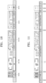
FIGS. 10 and 11 are diagrams illustrating content displayed on a see-through panel according to embodiments of the disclosure. - Embodiments of the disclosure will be described in detail with reference to the attached drawings, so that those skilled in the art may easily implement the disclosure. However, the disclosure may be implemented in many different forms and is not limited to the embodiments described herein. In order to clearly describe the disclosure in the drawings, parts not related to the description are omitted, and similar reference numerals are assigned to similar components throughout the specification.
- Throughout the specification, when a part is said to "include" a certain element, this means that it may further include other elements rather than excluding them, unless otherwise specified.
-
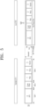
FIG. 1 is a diagram illustrating an exemplary front display including a plurality of display areas according to an embodiment of the disclosure. - It is assumed that a
front display 100 illustrated inFIG. 1 is disposed in front of a driver's seat and a passenger seat in a mobile device. In other words, thefront display 100 is preferably disposed across the front of the passenger seat as well as the front of the driver's seat in the mobile device. - The
front display 100 may measure a specific part (e.g., eye/nose position) of the driver's face through a camera (e.g., driver status monitor (DSM) camera) and adjust its height and inclination according to the position of the part. - Additionally, the
front display 100 according to the embodiment illustrated inFIG. 1 may include a plurality ofdisplay areas display areas FIG. 1 as specifically including afirst shy button 110, a first in-vehicle infotainment (IVI)display 120, asecond IVI display 130, and a secondshy button 140, they may be configured in various other forms. - The
shy buttons FIG. 1 , thefirst shy button 110 is a shy button providing a function (e.g., a driving control-related function) that the driver may use, when needed, and the secondshy button 140 is a shy button providing a function (e.g., a function related to music playback) that a passenger in the passenger seat may use, when needed. - The
first IVI display 120 may play a cluster related to the driver's driving, a cluster widget, a map, media, and a weather-related application, and reset an area in which an application is displayed according to the driver's (or passenger's) operation or condition settings. - The
second IVI display 130 may display applications that may be controlled by the passenger, such as weather-related control, media, and a map. - In an embodiment of the disclosure, it is proposed to support a low mode to secure the driver's forward vision among display modes. During a low-mode operation, the
front display 100 described above may be moved downward by a controller (not shown). - In an embodiment of the disclosure, it is further proposed to include a see-through
panel 150 as illustrated inFIG. 1 . As described above, thefront display 100 may be configured such that when thefront display 100 is moved downward by applying the low mode, light from a lower area of thefront display 100 provides information to the driver and the passenger through the see-throughpanel 150. - It is assumed that the information provided through the see-
through panel 150 corresponds to a screen displayed through each of thefirst shy button 110, thefirst IVI display 120, thesecond IVI display 130, and thesecond shy button 140. However, the information provided through the see-throughpanel 150 is preferably simplified information, compared to information displayed on an upper part of thefront display 100. "Simplified information" may refer to information that may be implemented at a low resolution, in a small amount, or in a combination of both, compared to information displayed in the upper part of thefront display 100. - As illustrated in
FIG. 1 , a cockpit system according to an embodiment of the disclosure may further include anoperating system 160. Theoperating system 160 may be implemented in a projection manner, as described later. -
FIG. 2 is a diagram illustrating a method of changing a cockpit layout according to a display mode in an embodiment of the disclosure. - In the embodiment illustrated in
FIG. 2 , a first mode may be selected, which is any one of a first mode group(S210) including a standard mode(S211), a low mode(S212), and a tilt-back mode(S213). The first mode group may refer to display modes that are classified according to the driver's conditions during driving. Although the first mode group may be set to include various types of modes such as a driver's seat up mode and a driver's seat tilt-back mode as well as the standard mode, the tilt-back mode, and the low mode, the following description will be given in the context of the above three examples of standard mode, tilt-back mode, and low mode, for convenience of description. - Selecting the first mode may include measuring a specific part (e.g., eye/nose position) of the driver's face through a camera (e.g., DSM camera) and selecting the first mode according to the position of the specific part.
- For example, when the position of the specific part is equal to or greater than a first reference height (e.g., 1m), which corresponds to a large driver's sitting height, the tilt-back mode may be applied to efficiently display the front display to the driver. When the position of the specific part is equal to or less than a second reference height (e.g., 70cm), which corresponds to a small driver's sitting height, the low mode may be applied to secure the driver's forward vision. Additionally, when the position of the specific part is between the first reference height and the second reference height, the standard mode may be applied to secure the forward vision and increase display efficiency depending on the driver's state.
- When the first mode selected in step S210 is the low mode, it is proposed in an embodiment of the disclosure to move the front display downward (S230), and provide information to the driver and passenger through the see-through panel by transmitting light from the lower area of the front display moved downward (S240), as described above with reference to
FIG. 1 . - Additionally, in an embodiment of the disclosure, when the first mode selected in step S210 is the low mode, the front display may be moved downward (S230), and a display interface may be changed (S250). That is, the front display may be moved downward, allowing the lower area of the display to transmit light to provide information to the driver and the passenger through the see-through panel, and an upper area other than the see-through area still displays information, while a screen interface may be changed to match the size of a screen exposed above the see-through panel. In other words, the interface may be automatically changed to display information according to the size of the lowered screen.
- The display interface change step S250 is shown in
FIG. 2 as following the see-through display step S240, which should not be construed as limiting. The order may be reversed or the steps may be performed simultaneously. -
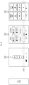
FIG. 3 is a diagram illustrating components of thefront display 100 according to an embodiment of the disclosure. Thefront display 100 may include adisplay panel 101, ablack masking layer 102, a deadfront layer 103, and afront glass 104. - The
display panel 101 may include a plurality ofdisplay areas - The plurality of
display areas - Additionally, upon detecting that the first display area is failed, the
front display 100 according to an embodiment of the disclosure may display information displayed on the first display area on the second display area. Traditionally, when a cluster and a control screen are configured on a single display, a fatal risk may occur when a problem such as malfunction occurs. In contrast, as the cockpit system according to an embodiment of the disclosure includes the plurality of displays, driving safety may be improved by allowing information to be displayed on another display even if a display area malfunctions. - In other words, safety and convenience may be improved by configuring a plurality of displays instead of a single display. Moreover, for an electric vehicle, only a required display may be activated to reduce the power consumption of the displays and secure a driving distance as much as the reduced power consumption.
- The
black masking layer 102 may be provided on the front surface of thedisplay panel 101 and shaped like a frame configured to cover border areas between the plurality of display areas in black. When thedisplay areas black masking layer 102 serving as a bezel of the display areas is preferably processed in real black to reduce contrast. - The dead
front layer 103 may be disposed on the front surface of the black masking layer and enable the front display to implement a dead front effect (DFE). The DFE means that when a display area is deactivated, the deactivated display area is indistinguishable from a part other than the display area. In other words, finish is performed such that when a screen is turned off, the presence of the display is not perceivable as if only an exterior material is visible, and the resulting differentiation of an interior design may increase the aesthetic effect. - The aesthetic effect may further be enhanced by representing a graphical user interface (GUI) on the screen in real black. When attention is required, only an information area that needs to attract attention may be displayed, while the DFE is implemented in the other areas, thereby eliminating factors of carelessness and improving driving safety.
- For finer representation, a gradation effect may be applied to both end edges of the dead
front layer 103 according to an embodiment of the disclosure. - The
front glass 104 may be disposed on the front surface of the dead front layer and serve as an outermost exterior material to protect the display panel. -
FIG. 4 is a detailed diagram illustrating a display position in each display mode according to an embodiment of the disclosure. - First, in the embodiment illustrated in
FIG. 4 , a display position for astandard mode 311 is preferably set to a height at which the bottom line of a display active area of the fist IVI display on the front display is not covered by the see-throughpanel 150. - Secondly, in the embodiment illustrated in
FIG. 4 , in a tilt-back mode 312, the height of the driver's eyes/nose may be measured as described above, and thefront display 100 may be adjusted to be tilted back accordingly to increase display efficiency for the driver (S310). Additionally, in a preferred embodiment of the disclosure, it may be configured that the tilt-back degree of thefront display 100 is finely adjusted through the firstshy button 110. - Lastly, in the embodiment illustrated in
FIG. 4 , in alow mode 313, the driver's eye/nose height may be measured and thefront display 100 may be moved downward to secure a forward vision (S320), as described above. In this case, as described above, it may be configured to provide simplified information by light emitted from the bottom of thefront display 100 through the see-throughpanel 150. - In an embodiment of the disclosure, in the
low mode 313, there are areas in lower parts of theshy buttons shy buttons shy buttons panel 150. Accordingly, theshy buttons low mode 313. -
FIG. 4 illustrates an embodiment in which theoperating system 160 is implemented in a projection manner using aninternal projector 410. To implement a display-type operating system 160, a light-emitting display such as a light emitting diode (LED) display may be used. However, there are many curves/curved surfaces in the interior space of the mobile device, specifically a vehicle, and the light-emitting display is difficult to implement in consideration of the interior characteristics. - Therefore, in an embodiment of the disclosure, the
operating system 160 may be configured in a projection manner using theinternal projector 410 at the front of the mobile device. As illustrated inFIG. 4 , theoperating system 160 may be advantageously implemented freely even in a space with various curves/curved surfaces. -
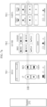
FIGS. 5 to 7 are diagrams illustrating an interface change in a low mode of a front display including a plurality of display areas according to an embodiment of the disclosure.FIG. 5 is a diagram illustrating an example of changing an interface on a screen of thefirst IVI display 120.FIG. 6 is a diagram illustrating an example of changing an interface on a screen of thesecond IVI display 130.FIG. 7 is a diagram illustrating an example of changing an interface on a screen of the firstshy button 110. Although a more specific embodiment is illustrated inFIG. 8 for the standard mode and inFIG. 9 for low mode,FIGS. 5 to 7 will be described first, for convenience of description of each configuration. - In the embodiment of
FIG. 5 , thefirst IVI display 120 is displayed separately into a cluster 120-1 displaying a vehicle speed, a cluster widget 120-2, and an IVI 120-3, by way of example. The IVI may provide an IVI display for the driver. WhileFIG. 5 illustrates an example of providing a map, media, and weather information, this is only an exemplary configuration, to which the disclosure is not limited. - First, in the embodiment illustrated in
FIG. 5 , because the display position is preferably set to a height at which the bottom line of the display active area of the first IVI display on thefront display 100 is not covered by the see-throughpanel 150 in thestandard mode 311, as described above, an interface on thefirst IVI display 120 may be configured in a layout using the entire display screen. - Next, in the embodiment illustrated in
FIG. 5 , the front display may be moved downward in thelow mode 313 to secure a forward vision (S320), as described above. In this case, the bottom of the screen on thefirst IVI display 120 is covered by the see-through panel by as much as the length of the downward movement. An area covered by the see-through panel may be configured to provide simplified information by light emitted from the bottom of the display through the see-throughpanel 150, as described above. - A part which is exposed above without being covered by the see-through panel may continue to provide information to the driver by applying an interface changed to suit the low mode. Herein, the size of the screen exposed above the see-through panel may be detected and calculated, and the interface may be automatically changed to match the size. As described later, since the user may finely adjust the height of the display using a button, the display screen may be reconfigured to match the height to which the downward movement is made. Changing the interface may include simply contracting the screen or changing the position and configuration of information provided on the display.
- In the embodiment of
FIG. 6 , thesecond IVI display 130 is displayed, by way of example. As illustrated inFIG. 6(a) , thesecond IVI display 130 may display applications controllable by the passenger, such as weather-related control, media, and maps. Alternatively, a full-screen application available to the driver and the passenger may be displayed, as illustrated inFIG. 6(b) . In this case, maps, media, and weather information may be provided. However, this is only an exemplary configuration, to which the disclosure is not limited. - First, in the embodiment illustrated in
FIG. 6 , since the bottom line of a display active area is preferably set to a height at which it is not covered by the see-through panel in thestandard mode 311, an interface on thesecond IVI display 130 may be configured in a layout using the entire screen. - Next, in the embodiment illustrated in
FIG. 6 , the front display may be moved downward in thelow mode 313 to secure a forward vision (S320), as described above. In this case, the bottom of the screen on thesecond IVI display 120 is covered by the see-through panel or a housing by as much as the length of the downward movement. An area covered by the see-through panel may be configured to provide simplified information by light emitted from the bottom of the display through the see-throughpanel 150, as described above. Alternatively, content may not be configured in the covered area. - A part which is exposed above without being covered by the see-through panel or the housing may continue to provide information to the driver by applying an interface changed to suit the low mode. Herein, the size of the screen exposed above the see-through panel may be detected and calculated, and the interface may be automatically changed to match the size. As described later, since the user may finely adjust the height of the display using a button, the display screen may be reconfigured to match the height to which the downward movement is made. Changing the interface may include simply contracting the screen or changing the position and configuration of information provided on the display.
- In the embodiment of
FIG. 7 , the firstshiny button 110 is displayed in the standard mode and the low mode, by way of example. The firstshy button 110 may provide functions (e.g., driving control-related functions) that the driver may use when needed. Additionally, the firstshy button 110 may be configured with an application with multiple pages based on the firstshy button 110 being a display. -
FIG. 7 illustrates an example in which the firstshy button 110 includes a front display control button 110-1 onpage 1, a driver and passenger seat mode setting button 110-2 onpage 2, and a user-set favorite button 110-3 onpage 3. However, this is an exemplary configuration, to which the disclosure is not limited. Each page may be turned by a flicking or slide touch input (S700), and the order and configuration of the pages may be set by the user. - First, in the embodiment illustrated in
FIG. 7 , since the bottom line of a display active area is preferably set to a height at which it is not covered by the see-through panel in thestandard mode 311, an interface of the firstshy button 110 may be configured in a layout using the entire screen. In this case, more specific and more information may be displayed. - Next, in the embodiment illustrated in
FIG. 7 , the front display may be moved downward in thelow mode 313 to secure a forward vision (S320), as described above. In this case, the bottom of the screen of the firstshy button 110 is covered by the see-through panel by as much as the length of the downward movement. An area covered by the see-through panel may be configured to provide simplified information by light emitted from the bottom of the display through the see-throughpanel 150, as described above. Alternatively, content may not be configured in the covered area, as illustrated. - In the
low mode 313, there is an area in the lower part of theshy button 110, which is covered due to the downward movement of the display, and in view of the nature of theshy button 110, it may not be efficient to use light from the bottom of theshy button 110 to provide information through the see-throughpanel 150. Accordingly, theshy button 110 may be configured such that the arrangement of buttons is changed to maintain an existing function of the shy button in an area that is not covered in thelow mode 313. - A part which is exposed above without being covered by the see-through panel may continue to provide information to the driver by applying an interface changed to suit the low mode. Herein, the size of the screen exposed above the see-through panel may be detected and calculated, and the interface may be automatically changed to match the size. As described later, since the user may finely adjust the height of the display using a button, the display screen may be reconfigured to match the height to which the downward movement is made. Changing the interface may include simply contracting the screen or changing the position and configuration of information provided on the display.
-
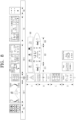
FIG. 8 is a diagram illustrating content displayed on a front display in a standard mode during a driving mode according to an embodiment of the disclosure. - In the embodiment of
FIG. 8 , the front display is also shown as including the firstshiny button 110, thefirst IVI display 120, thesecond IVI display 130, and the secondshiny button 140, as in the example ofFIG. 1 . Among them, thefirst IVI display 120 is displayed separately into the cluster 120-1, the cluster widget 120-2, and the IVI 120-3, by way of example. - Specifically, the cluster 120-1 may display a cluster screen related to driving information, and
FIG. 8 illustrates an example of displaying driving navigation information, a vehicle speed, a driving distance, and a battery state of an electric vehicle. - The cluster widget 120-2 displays information in the form of a widget, and
FIG. 8 illustrates an example in which warning information A, virtual personal assistant (VPA) B, turn by turn (TBT) C, and an information-type widget D are selected with first to fourth priorities, respectively. However, this is an exemplary configuration, to which the disclosure is not limited. - Additionally, the IVI 120-3 may provide an IVI display for the driver, unlike the
second IVI display 130 for the passenger seat. AlthoughFIG. 8 illustrates an example of providing maps, media, and weather information, this is only an exemplary configuration, to which the disclosure is not limited. - In the embodiment illustrated in
FIG. 8 , the operating system is divided into adriver operating system 810, anHVAC operator 820, and apassenger operating system 830. In addition, an upper part of the operating system includes anoperation button unit 840 displayed in the form of a shortcut, and the position of the shortcut is preferably exchanged with the position of an animation form in a lower part. -
FIG. 9 is a diagram illustrating content displayed on a front display in a low mode during a driving mode according to an embodiment of the disclosure. - In the embodiment of
FIG. 9 , it is also assumed that a plurality of display areas of the front display are the same as in the embodiment ofFIG. 8 . However, it is configured that as the low mode is applied, the front display is moved downward (S910), and light emitted from the lower area of the front display provides additional information through the see-throughpanel 150. - Preferably, a display through the see-through
panel 150 displays simplified information, compared to the upper area of the front display, and a background color 150-1 is preferably a subdued color that may provide comfort to the driver/passenger. However, when information provided through the see-throughpanel 150 delivers a warning message to the driver/passenger, the see-through display is preferably performed by applying an intense color 150-2 that may provide alertness. - In the embodiment of
FIG. 9 , there are areas in the lower parts of theshy buttons shy buttons shy buttons panel 150. Accordingly, it is proposed that theshy buttons low mode 313, unlike the IVI displays 120 and 130 (S910). - Additionally, the embodiment of
FIG. 9 proposes that a separate light-emitting display 910 (e.g., an LED display) is disposed in an area in which a see-through display through the see-throughpanel 150 may not be performed, in a border area between a plurality of display areas. This light-emittingdisplay 910 may be configured to provide additional information, and as described later, serve as an indoor mood light together with the see-throughdisplay area 150. -
FIGS. 10 and 11 are diagrams illustrating content displayed through a see-through panel according to embodiments of the disclosure. - As described above, when the low mode is applied, the front display may move downward with the plurality of display areas as a unit, and light from the lower area of the front display may display simplified information through the see-through
panel 150, compared to information displayed in the upper area of the front display. - As in the embodiment of
FIG. 10 , the information displayed through the see-through panel may include information corresponding to each of the plurality of display areas in the upper part of the front display. That is, when the plurality of display areas of the front display include the firstshy button 110, thefirst IVI display 120, thesecond IVI display 130, and the secondshy button 140, and among them, thefirst IVI display 120 is divided into the cluster 120-1, the cluster widget 120-2, and the IVI 120-3 as described above, information corresponding to each of these areas may be displayed through the see-throughpanel 150. - In the embodiment of
FIG. 10 , when driving information is displayed through the cluster 120-1, information displayed through the corresponding see-throughpanel 150 may be a driving-related warning message 120-1/150, which is simplified information corresponding to the driving information. In addition, when a specific widget is performed through the IVI 120-3 and/or thesecond IVI display 130, a shortcut function button 120-3/150 and/or 130/150 of the specific widget may be displayed through a corresponding area of the see-throughpanel 150. - The
shy buttons shy buttons reference numerals 110/150 and/or 140/150. That is, unlike the IVI displays, theshy buttons panel 150. - In some cases, however, function buttons corresponding to the upper parts of the
shy buttons shy buttons panel 150. - The see-through panel may include a touch input-enabled configuration. The see-through panel may be configured as a touch screen. As described above, when a simplified icon is displayed through the see-through panel, the user may execute a corresponding function by touching the icon on the see-through panel.
- In the embodiment illustrated in
FIG. 11 , the whole see-throughpanel 150 may be configured to perform the function of amood lamp 1110 for interior decoration, instead of providing specific information. In this case, as described above with reference toFIG. 9 , anuninterrupted mood lamp 1110 may be configured using the light-emittingdisplay 910 at each of borders between the areas as well as the see-throughpanel 150. Even in an embodiment in which the see-throughpanel 150 and the light-emittingdisplay 910 are used as themood lamp 1110, driving-related warning information may be provided through a color of themood lamp 1110. - According to the embodiments of the disclosure described above, a method of changing a cockpit layout according to a display mode and a cockpit system using the same may be efficiently configured.
- Specifically, in an embodiment of the disclosure, as a plurality of display areas are provided instead of a single display providing multiple pieces of information, individual control is possible, thereby increasing convenience. When one display malfunctions, information may be displayed on another display, thereby significantly increasing driving safety.
- Further, aesthetics may be enhanced by providing a display panel that realizes the DFE.
- Further, in an embodiment of the disclosure, the forward vision of a driver may be easily secured through a low mode even during a driving mode, and information may also be provided to the driver and a passenger by transmitting light from a lower area of a front display through a see-through display even in the low mode.
- Further, simplified information and a touch function may be provided through a see-through display, thereby increasing user convenience.
- As described above, a detailed description of preferred embodiments of the disclosure has been given to enable those skilled in the art to implement and practice the disclosure. While the above description has been made with reference to the preferred embodiments of the disclosure, it will be understood by those skilled in the art that various modifications and changes may be made to the disclosure without departing from the scope of the disclosure. For example, those skilled in the art may use the configurations described in the above-described embodiments in combination with each other.
- Accordingly, the embodiments as set forth herein are not intended to limit the disclosure, but rather to give the broadest possible scope consistent with the principles and novel features disclosed herein.
Claims (10)
- A cockpit system with a layout changed according to a display mode in a mobile device, comprising:a front display disposed in front of a driver's seat and a passenger seat of the mobile device;a controller configured to move the front display upward and downward and to tilt the front display; anda see-through panel configured to, when a low mode among display modes is applied, transmit light from a lower area of the front display to provide information to the driver and a passenger, after the front display is moved downward,wherein the front display includes a display panel including a plurality of display areas, andwherein when at least one of the plurality of display areas is deactivated, a dead front effect is represented to make the deactivated display area indistinguishable from a part other than the deactivated display area.
- The cockpit system of claim 1, wherein the front display further includes:a black masking layer attached to a front surface of the display panel and covering a border area between the display areas in black;a dead front layer disposed on a front surface of the black masking layer and configured to represent the dead front effect; anda front glass disposed on a front surface of the dead front layer to protect the display panel.
- The cockpit system of claim 1, or 2, wherein the display modes include:a standard mode in which the front display is located at a preset position;a tilt-back mode in which the front display is moved upward and tilted in a direction away from the driver; andthe low mode in which the front display is moved downward.
- The cockpit system of claim 1, 2, or 3, wherein in the low mode, an interface on an activated screen in the plurality of display areas is changed to match a size of a screen exposed above the see-through panel in the activated screen.
- The cockpit system of any one of claims 1 to 4, wherein the display panel includes a separate light-emitting display in an area that does not allow a see-through display to be performed through the see-through panel among border areas between the plurality of display areas.
- The cockpit system of any one of claims 1 to 5, wherein the plurality of display areas of the front display includes a first shy button, a first in-vehicle infotainment (IVI) display, a second IVI display, and a second shy button.
- The cockpit system of claim 6, wherein when the low mode is applied, the information provided through the see-through panel is information corresponding to a screen displayed through each of the first shiny button, the first IVI display, the second IVI display, and the second shy button, and more simplified than information displayed through an upper part of the front display.
- The cockpit system of any one of claims 1 to 7, wherein a touch input is applicable on the see-through panel.
- The cockpit system of any one of claims 1 to 8, wherein the plurality of display areas include a first display area and a second display area, and
wherein when failure of the first display area is detected, information displayed on the first display area is displayed on the second display area. - A method of changing a cockpit layout according to a display mode in a mobile device, the method comprising:selecting a first mode from a first mode group including a standard mode, a tilt-back mode, and a low mode;when the first mode is the low mode, moving a front display downward;providing information to a driver and a passenger through a see-through panel by transmitting light from a lower area of the front display moved downward; andchanging an interface on an activated screen of the front display moved downward to match a size of a screen exposed above the see-through panel.
Applications Claiming Priority (1)
| Application Number | Priority Date | Filing Date | Title |
|---|---|---|---|
| KR1020230195051A KR20250102892A (en) | 2023-12-28 | 2023-12-28 | Method for Adjusting Cockpit Layout based on Display Mode and Cockpit System using the Same |
Publications (1)
| Publication Number | Publication Date |
|---|---|
| EP4578692A1 true EP4578692A1 (en) | 2025-07-02 |
Family
ID=92264128
Family Applications (1)
| Application Number | Title | Priority Date | Filing Date |
|---|---|---|---|
| EP24193270.6A Pending EP4578692A1 (en) | 2023-12-28 | 2024-08-07 | Method of changing cockpit layout according to display mode and cockpit system using the same |
Country Status (4)
| Country | Link |
|---|---|
| US (1) | US20250214428A1 (en) |
| EP (1) | EP4578692A1 (en) |
| KR (1) | KR20250102892A (en) |
| CN (1) | CN120229098A (en) |
Citations (5)
| Publication number | Priority date | Publication date | Assignee | Title |
|---|---|---|---|---|
| US20160193923A1 (en) * | 2015-01-02 | 2016-07-07 | Hyundai Motor Company | Vehicle including display apparatus |
| US9676332B2 (en) * | 2013-08-12 | 2017-06-13 | GM Global Technology Operations LLC | Panorama projection unit for a motor vehicle |
| US20190344664A1 (en) * | 2018-05-11 | 2019-11-14 | Motherson Innovations Company Limited | Multifunction device and dashboard with such a device |
| DE102018212445A1 (en) * | 2018-07-25 | 2020-03-05 | Volkswagen Aktiengesellschaft | Display and control device for a motor vehicle |
| US20230302906A1 (en) * | 2017-12-21 | 2023-09-28 | Samsung Electronics Co., Ltd. | Method and device for controlling display on basis of driving context |
Family Cites Families (3)
| Publication number | Priority date | Publication date | Assignee | Title |
|---|---|---|---|---|
| US9895975B2 (en) * | 2015-06-05 | 2018-02-20 | Lg Display Co., Ltd. | Bar type display apparatus and vehicle comprising the same |
| EP4491431A4 (en) * | 2022-03-14 | 2025-05-14 | LG Electronics Inc. | VEHICLE DISPLAY DEVICE |
| US12353707B2 (en) * | 2023-05-18 | 2025-07-08 | AUO Corporation | Multi-screen cockpit display system |
-
2023
- 2023-12-28 KR KR1020230195051A patent/KR20250102892A/en active Pending
-
2024
- 2024-07-12 US US18/770,939 patent/US20250214428A1/en active Pending
- 2024-08-07 EP EP24193270.6A patent/EP4578692A1/en active Pending
- 2024-08-29 CN CN202411202536.1A patent/CN120229098A/en active Pending
Patent Citations (5)
| Publication number | Priority date | Publication date | Assignee | Title |
|---|---|---|---|---|
| US9676332B2 (en) * | 2013-08-12 | 2017-06-13 | GM Global Technology Operations LLC | Panorama projection unit for a motor vehicle |
| US20160193923A1 (en) * | 2015-01-02 | 2016-07-07 | Hyundai Motor Company | Vehicle including display apparatus |
| US20230302906A1 (en) * | 2017-12-21 | 2023-09-28 | Samsung Electronics Co., Ltd. | Method and device for controlling display on basis of driving context |
| US20190344664A1 (en) * | 2018-05-11 | 2019-11-14 | Motherson Innovations Company Limited | Multifunction device and dashboard with such a device |
| DE102018212445A1 (en) * | 2018-07-25 | 2020-03-05 | Volkswagen Aktiengesellschaft | Display and control device for a motor vehicle |
Also Published As
| Publication number | Publication date |
|---|---|
| US20250214428A1 (en) | 2025-07-03 |
| CN120229098A (en) | 2025-07-01 |
| KR20250102892A (en) | 2025-07-07 |
Similar Documents
| Publication | Publication Date | Title |
|---|---|---|
| EP3691926B1 (en) | Display system in a vehicle | |
| US11005720B2 (en) | System and method for a vehicle zone-determined reconfigurable display | |
| US20200067786A1 (en) | System and method for a reconfigurable vehicle display | |
| EP2305508B1 (en) | User configurable vehicle user interface | |
| US20160070456A1 (en) | Configurable heads-up dash display | |
| CN107351763B (en) | Control device for vehicle | |
| US20130293452A1 (en) | Configurable heads-up dash display | |
| US20130293364A1 (en) | Configurable dash display | |
| KR101730315B1 (en) | Electronic device and method for image sharing | |
| EP4578697A1 (en) | Cockpit system and method of controlling same | |
| KR20230124484A (en) | Heads up display | |
| JP2020126282A (en) | Input system and input method | |
| US20250214428A1 (en) | Method of changing cockpit layout according to display mode and cockpit system using the same | |
| KR102246498B1 (en) | Cockpit module for autonomous vehicle and method for controlling display module position | |
| US20250214437A1 (en) | Method of changing cockpit layout according to display mode and cockpit system using the same | |
| JP2017178300A (en) | Vehicular information providing device | |
| US20250214426A1 (en) | Cockpit system and mobile device | |
| EP4578699A1 (en) | Cockpit system and vehicle therefor | |
| WO2022168696A1 (en) | Display system for displaying gesture operation result | |
| KR20250102569A (en) | Cockpit system with operating system using projector |
Legal Events
| Date | Code | Title | Description |
|---|---|---|---|
| PUAI | Public reference made under article 153(3) epc to a published international application that has entered the european phase |
Free format text: ORIGINAL CODE: 0009012 |
|
| STAA | Information on the status of an ep patent application or granted ep patent |
Free format text: STATUS: THE APPLICATION HAS BEEN PUBLISHED |
|
| AK | Designated contracting states |
Kind code of ref document: A1 Designated state(s): AL AT BE BG CH CY CZ DE DK EE ES FI FR GB GR HR HU IE IS IT LI LT LU LV MC ME MK MT NL NO PL PT RO RS SE SI SK SM TR |
|
| STAA | Information on the status of an ep patent application or granted ep patent |
Free format text: STATUS: REQUEST FOR EXAMINATION WAS MADE |
|
| 17P | Request for examination filed |
Effective date: 20251222 |
|
| GRAP | Despatch of communication of intention to grant a patent |
Free format text: ORIGINAL CODE: EPIDOSNIGR1 |
|
| STAA | Information on the status of an ep patent application or granted ep patent |
Free format text: STATUS: GRANT OF PATENT IS INTENDED |
|
| INTG | Intention to grant announced |
Effective date: 20260407 |
|
| GRAS | Grant fee paid |
Free format text: ORIGINAL CODE: EPIDOSNIGR3 |