EP4578676A1 - Latch device for vehicle door - Google Patents
Latch device for vehicle door Download PDFInfo
- Publication number
- EP4578676A1 EP4578676A1 EP22956395.2A EP22956395A EP4578676A1 EP 4578676 A1 EP4578676 A1 EP 4578676A1 EP 22956395 A EP22956395 A EP 22956395A EP 4578676 A1 EP4578676 A1 EP 4578676A1
- Authority
- EP
- European Patent Office
- Prior art keywords
- catch
- release
- lever
- pawl
- drive element
- Prior art date
- Legal status (The legal status is an assumption and is not a legal conclusion. Google has not performed a legal analysis and makes no representation as to the accuracy of the status listed.)
- Pending
Links
Images






Classifications
-
- E—FIXED CONSTRUCTIONS
- E05—LOCKS; KEYS; WINDOW OR DOOR FITTINGS; SAFES
- E05B—LOCKS; ACCESSORIES THEREFOR; HANDCUFFS
- E05B81/00—Power-actuated vehicle locks
- E05B81/12—Power-actuated vehicle locks characterised by the function or purpose of the powered actuators
- E05B81/14—Power-actuated vehicle locks characterised by the function or purpose of the powered actuators operating on bolt detents, e.g. for unlatching the bolt
-
- E—FIXED CONSTRUCTIONS
- E05—LOCKS; KEYS; WINDOW OR DOOR FITTINGS; SAFES
- E05B—LOCKS; ACCESSORIES THEREFOR; HANDCUFFS
- E05B15/00—Other details of locks; Parts for engagement by bolts of fastening devices
- E05B15/004—Lost motion connections
-
- E—FIXED CONSTRUCTIONS
- E05—LOCKS; KEYS; WINDOW OR DOOR FITTINGS; SAFES
- E05B—LOCKS; ACCESSORIES THEREFOR; HANDCUFFS
- E05B77/00—Vehicle locks characterised by special functions or purposes
- E05B77/14—Specially controlled locking actions in case of open doors or in case of doors moved from an open to a closed position, e.g. lock-out prevention or self-cancelling
- E05B77/18—Keyless locking with self-cancellation, e.g. resulting in an unlocking action when the door is being closed
- E05B77/20—Override of self-cancellation, e.g. by actuation of the handle while the door is being closed
-
- E—FIXED CONSTRUCTIONS
- E05—LOCKS; KEYS; WINDOW OR DOOR FITTINGS; SAFES
- E05B—LOCKS; ACCESSORIES THEREFOR; HANDCUFFS
- E05B81/00—Power-actuated vehicle locks
- E05B81/12—Power-actuated vehicle locks characterised by the function or purpose of the powered actuators
- E05B81/20—Power-actuated vehicle locks characterised by the function or purpose of the powered actuators for assisting final closing or for initiating opening
-
- E—FIXED CONSTRUCTIONS
- E05—LOCKS; KEYS; WINDOW OR DOOR FITTINGS; SAFES
- E05B—LOCKS; ACCESSORIES THEREFOR; HANDCUFFS
- E05B81/00—Power-actuated vehicle locks
- E05B81/24—Power-actuated vehicle locks characterised by constructional features of the actuator or the power transmission
- E05B81/32—Details of the actuator transmission
- E05B81/34—Details of the actuator transmission of geared transmissions
- E05B81/36—Geared sectors, e.g. fan-shaped gears
-
- E—FIXED CONSTRUCTIONS
- E05—LOCKS; KEYS; WINDOW OR DOOR FITTINGS; SAFES
- E05B—LOCKS; ACCESSORIES THEREFOR; HANDCUFFS
- E05B81/00—Power-actuated vehicle locks
- E05B81/54—Electrical circuits
- E05B81/64—Monitoring or sensing, e.g. by using switches or sensors
- E05B81/66—Monitoring or sensing, e.g. by using switches or sensors the bolt position, i.e. the latching status
-
- E—FIXED CONSTRUCTIONS
- E05—LOCKS; KEYS; WINDOW OR DOOR FITTINGS; SAFES
- E05B—LOCKS; ACCESSORIES THEREFOR; HANDCUFFS
- E05B81/00—Power-actuated vehicle locks
- E05B81/54—Electrical circuits
- E05B81/64—Monitoring or sensing, e.g. by using switches or sensors
- E05B81/76—Detection of handle operation; Detection of a user approaching a handle; Electrical switching actions performed by door handles
Definitions
- the present invention relates to a latch device for a vehicle door.
- a latch device for a vehicle door which includes a power cinching mechanism that displaces a latch from a half-latched position to a fully-latched position (Patent Document 1).
- the latch device described in this document is attached to the back door of a vehicle and has a catch (24), a cinch lever (21), and a pawl (25).
- the latch device engages/releases the catch (24) and a striker (7) provided on the body side, thereby displacing the back door between the half-latched position and the fully-latched position.
- the cinch lever operated by an actuator rotates the catch in the latch direction, thereby displacing the catch from the half-latched position to the fully-latched position, but the cinch lever is located behind the catch in the latch direction.
- the inventors have confirmed that when the driver operates to close the door and the door is in the half-latched position, if the driver operates to open the door in the opposite direction and to return the catch to the state before the half-latch, the cinch lever, which is located behind the catch in the half-latched position, will come to the front side of the catch. When such an irregular state occurs, a problem may arise in that the cinch lever is mechanically locked and the return operation cannot be performed.
- a problem to be solved by the present invention is to provide a latch device for a vehicle door that, even if the positional relationship between the catch and the cinch lever becomes an irregular state, can recover the normal positional relationship.
- the present invention solves the above problem through providing one of a drive element, which is rotated by an actuator, and a cinch lever with a rotation restricting section that restricts a rotation range of the drive element depending on a rotation position of the cinch lever and configuring the rotation restricting section such that when a catch is in a position between a fully-latched position and an unlatched position and the cinch lever is located forward of a contact portion of the catch in the latch direction of the catch, the drive element comes into contact with a release member to allow the release member to rotate in a counter-restriction direction.
- the latch device 1 for a vehicle door of the present embodiment which is attached to the vehicle door side, engages with a striker 2 to put the vehicle door into a closed state and is released from the striker 2 to put the vehicle door into an opened state.
- the striker 2 is fixed to the body side of the vehicle, for example, the back door opening portion, the side door opening portion, the trunk opening portion, etc.
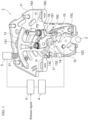
- the latch device 1 for a vehicle door of the present embodiment includes a base plate 11, to which a catch 12, a sector gear 13, a cinch lever 14, a pawl 15, and a release lever 16 are each rotatably attached.
- the base plate 11 to which these elements are attached is then fixed to a vehicle door (not illustrated), such as a back door, using bolts or the like.
- the striker 2 is configured by bending a solid round bar of steel material, and is fixed to the vehicle body side. Only its cross section is illustrated in FIG. 1 .
- the sector gear 13 is an example of the drive element according to the present invention
- the pawl 15 and release lever 16 are an example of the release member according to the present invention.
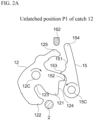
- FIG. 2A is a front view illustrating an unlatched state of the catch 12 and pawl 15 (unlatched position P1 of the catch 12)
- FIG. 2B is a front view illustrating a half-latched state of the catch 12 and pawl 15 (half-latched position P2 of the catch 12)
- FIG. 2C is a front view illustrating a fully-latched state of the catch 12 and pawl 15 (fully-latched position P3 of the catch 12).
- the catch 12 rotates between the unlatched position P1 in which the striker 2 is released as illustrated in FIG. 2A and the fully-latched position P3 in which the striker 2 is fully gripped as illustrated in FIG. 2C , and passes through the half-latched position P2 in which the striker 2 is half-gripped as illustrated in FIG. 2B .
- the rotation direction toward the fully-latched position P3 is called the latch direction
- the rotation direction toward the unlatched position P1 is called the release direction.
- the direction in which the catch 12 rotates clockwise is the release direction
- the direction in which the catch 12 rotates counterclockwise is the latch direction.
- latch direction and release direction are used not only to refer to the rotation direction of the catch 12, but also to the rotation directions of the sector gear 13, cinch lever 14, pawl 15, and release lever 16 that constitute the latch device 1. That is, upon rotation of these elements, the rotation direction when the latch device 1 operates to be latched is called the latch direction, and the rotation direction when the latch device 1 operates to be released is called the release direction.
- the catch 12 is elastically biased in the release direction, that is, the clockwise direction illustrated in FIG. 1 , but the rotation in the release direction is restricted at the unlatched position P1 illustrated in FIG. 2A by a stopper (not illustrated). That is, the catch 12 is configured so as not rotate further in the release direction (clockwise direction) than the unlatched position P1 illustrated in FIG. 2A . In the state in which the vehicle door is open, the catch 12 waits for engagement with the striker 2 at the unlatched position P1 illustrated in FIG. 2A .
- the catch 12 is composed of a flat metal material or synthetic resin material and, as illustrated in FIG. 2C , includes a first convex portion 121 that engages with a first concave portion 151 of the pawl 15 at the fully-latched position P3, a second convex portion 122 that engages with a second concave portion 152 of the pawl 15, and a notch portion 123 with which the striker 2 engages.
- the first convex portion 121 of the catch 12 engages with the first concave portion 151 of the pawl 15, and the second convex portion 122 of the catch 12 engages with the second concave portion 152 of the pawl 15. This allows the catch 12 to be restrained at the fully-latched position P3 illustrated in FIG. 2C against the elastic bias acting in the release direction.
- the catch 12 includes a first concave portion 124 that engages with a first convex portion 153 of the pawl 15 at the half-latched position P2.
- the first convex portion 153 of the pawl 15 engages with the first concave portion 124 of the catch 12. This allows the catch 12 to be temporarily restrained at the half-latched position P2 illustrated in FIG. 2B against the elastic bias acting in the release direction.
- the catch 12 also includes a contact portion 125 that comes into contact with the cinch lever 14.
- the sector gear 13 and the cinch lever 14 are attached to the base plate 11 by the same rotation shaft 13C.
- the sector gear 13, which is a gear formed in a sector shape, is connected to an actuator 3 so that a teeth portion 131 of the sector gear 13 meshes with a teeth portion 31 of the actuator 3.
- the sector gear 13 of the present embodiment corresponds to the drive element according to the present invention, but the drive element according to the present invention may be any member that is rotated by the actuator 3 and acts on the cinch lever 14 and release lever 16 as described later, and is not limited to only the sector gear 13.
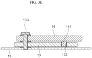
- the sector gear 13 is also formed with a curved, elongated groove 132 through which a pin 141 of the cinch lever 14 passes (see also the cross-sectional view of FIG. 3E ).
- the position illustrated in FIG. 1 is a neutral position, and the sector gear 13 is provided so as to be rotatable in both clockwise and counterclockwise directions.
- the direction in which the sector gear 13 rotates clockwise is the latch direction, and the direction in which the sector gear 13 rotates counterclockwise is the release direction.
- the groove 132 and pin 141 of the present embodiment are an example of the rotation restricting section according to the present invention.
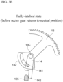
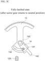
- FIGS. 3A to 3E are front views each illustrating the relationship between the sector gear 13 and the cinch lever 14.
- FIG. 3A illustrates the unlatched state or half-latched state
- FIG. 3B illustrates the fully-latched state before the sector gear 13 returns to the neutral position
- FIG. 3C illustrates the fully-latched state after the sector gear 13 returns to the neutral position
- FIG. 3D illustrates the release operation of the sector gear 13 and cinch lever 14
- FIG. 3E is a cross-sectional view taken along line IIIE-IIIE of FIG. 3A .
- the cinch lever 14 is elastically biased in the release direction relative to the sector gear 13, that is, the counterclockwise direction in the figure.
- the cinch lever 14 also has the pin 141 that passes through the groove 132 of the sector gear 13, and in the state in which no other load is acting on the cinch lever 14, the cinch lever 14 is elastically biased in the release direction and stops at a position at which the pin 141 abuts against the right end of the groove 132, thus restricting further rotation in the release direction.
- the sector gear 13 Upon release from the fully-latched state illustrated in FIG. 3C , the sector gear 13 rotates counterclockwise from the neutral position as illustrated in FIG. 3D , and comes into contact with a first contact portion 161 of the release lever 16 to push it. As will be described in detail later, this releases the rotation restriction on the catch 12 via the release lever 16 and the pawl 15, and the striker 2 is released.
- the cinch lever 14 which is elastically biased counterclockwise relative to the sector gear 13, also rotates counterclockwise.
- the space for the layout of the components of the latch device 1 is limited, when the cinch lever 14 rotates counterclockwise, there may not be enough space to ensure that it does not interfere with other components.
- the controller 5 operates to: drive and control the actuator 3; drive the sector gear 13 to rotate in the latch direction (clockwise direction) to rotate the cinch lever 14 in the latch direction; and rotate the catch 12 from the half-latched position P2 to the fully-latched position P3.
- the controller 5 operates to: drive and control the actuator 3; drive the sector gear 13 to rotate in the latch direction (clockwise direction) to rotate the cinch lever 14 in the latch direction; and rotate the catch 12 from the half-latched position P2 to the fully-latched position P3.
- This state is illustrated in the center diagram of FIG. 4 . This results in the fully-latched state, and the detection signal from the sensor 4 for the half-latched position P2 of the catch 12 stops, so the half-shut warning light displayed on the instrument panel or the like turns off.
- FIG. 6 is a set of perspective views of the latch device for explaining the cause of an irregular positional relationship between the catch 12 and the cinch lever 14
- FIG. 7 is an enlarged front view of the sector gear 13, cinch lever 14, and catch 12 illustrated in the right diagram of FIG. 6
- FIG. 8 is a front view illustrating the operation of returning from the irregular positional relationship illustrated in FIG. 7 .
- FIG. 6 is a perspective view illustrating this state.
- FIG. 6 illustrates the half-latched state, and as the catch 12 rotates to the half-latched position P2, the sensor 4 detects this and the controller 5 starts to rotate the sector gear 13 in the latch direction (clockwise direction), but at this time, as illustrated in the center diagram, when the driver performs an operation to open the door, the striker 2 causes reverse rotation of the catch 12 in the release direction.
- the relationship in a normal latch operation in which the contact portion 142 of the cinch lever 14 is located behind the contact portion 125 of the catch 12 in the latch direction of the catch 12 as illustrated in FIG. 3B becomes an irregular relationship in which, as illustrated in FIG.
- the contact portion 142 of the cinch lever 14 is located forward of the contact portion 125 of the catch 12 in the latch direction of the catch 12.
- the groove 132 of the sector gear 13 is provided with the second groove 132Y so that the sector gear 13 can rotate in the release direction when the driver presses the door open switch even in the irregular positional relationship illustrated in FIG. 7 .
- the groove 132 of the sector gear 13 is composed of the first groove 132X that functions when the catch 12 and the cinch lever 14 are in a normal positional relationship and the second groove 132Y that functions during the return operation when the catch 12 and the cinch lever 14 are in an irregular positional relationship.
- the catch 12 rotates to the fully-latched position P3 and is restrained by the pawl 15, or the catch 12 remains in the half-latched position P2 and is temporarily restrained by the pawl 15, but in either case, the rotation of the catch 12 is restricted by the pawl 15. It is therefore necessary to rotate the sector gear 13 in the release direction (clockwise direction) to rotate the release lever 16 in the release direction, thereby rotating the pawl 15 in the release direction.
- the second measure taken to enable the normal positional relationship to be recovered by performing the release operation even if the irregular positional relationship illustrated in FIG. 7 occurs is to provide the base plate 11 with a stopper 17 as illustrated in FIG. 1 .
- a warning display that the door is half-shut is displayed to alert the driver. Accordingly, if the half-shut door display is not turned off even after the door closing operation, the driver will assume that some kind of abnormality occurs and will open the door again and perform the tightening operation.
- the base plate 11 is provided with the stopper 17, and as illustrated in FIG. 7 , when the contact portion 142 of the cinch lever 14 is located forward of the contact portion 125 of the catch 12 in the latch direction of the catch 12, the rotation of the cinch lever 14 in the latch direction is restricted so as to prevent the catch 12 from reaching the fully-latch position P3.
- the stopper 17 By providing this stopper 17, the rotation of the contact portion 125 of the catch 12 in the latch direction is restricted, so that the half-latched position P2 is maintained and the driver can be presented with a warning display of the half-shut door.
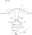
- FIG. 9A is a front view illustrating the sector gear 13 and cinch lever 14 of another embodiment of the latch device 1 for a vehicle door according to the present invention
- FIG. 9B is a cross-sectional view taken along line IXB-IXB of FIG. 9A .
- FIGS. 9A illustrates the embodiment illustrated in FIGS.
- the cinch lever 14 is provided with a groove 143 and the sector gear 13 is provided with a pin 133 that engages with the groove 143, so the first groove 132X in the above-described embodiment corresponds to a first groove 143X located on the left side of the groove 143 in the present embodiment, and the second groove 132Y in the above-described embodiment corresponds to a second groove 143Y located on the right side of the groove 143 in the present embodiment.
- the groove 143 and pin 133 in the present embodiment are an example of the rotation restricting section according to the present invention.
- the latch device 1 for a vehicle door of the present embodiment is provided on the door side of a vehicle.
- the latch device 1 includes the catch 12 that is provided to be elastically biased in the release direction toward the unlatched position so that the catch 12 can rotate in the latch direction toward the fully-latched position and in the release direction.
- the catch 12 engages with the striker 2 provided on the body side of the vehicle.
- the rotation restricting section is a groove 132, 143 with which the pin 141, 133 provided on the other of the sector gear 13 and the cinch lever 14 engages, and the groove 132, 143 is shaped such that when the catch 12 is in a position between the fully-latched position P3 and the unlatched position P1 and the cinch lever 14 is located forward of the contact portion 125 of the catch 12 in the latch direction of the catch 12, the pin 141, 133 can move through the groove 132, 143 to a position at which the sector gear 13 comes into contact with the release lever 16.
- the groove 132, 143 includes a first groove 132X, 143X and a second groove 132Y 143Y, and the second groove 132Y 143Y is such that, provided that the catch 12 is in a position between the fully-latched position P3 and the unlatched position P1 and the cinch lever 14 is located forward of the contact portion 125 of the catch 12 in the latch direction of the catch 12, the pin 141, 133 moves while engaging with the second groove 132Y 143Y when the sector gear 13 rotates to a position at which it comes into contact with the release lever 16.
- the drive element includes a sector gear 13
- the release member includes a pawl 15 and a release lever 16
- the pawl 15 comes into contact with the catch 12 so as to restrict rotation of the catch 12 in the release direction and is elastically biased in the restriction direction
- the release lever 16 comes into contact with the pawl 15 upon contact with the sector gear 13 and rotates the pawl 15 in the counter-restriction direction against the elastic bias.
- the latch device 1 for a vehicle door of the present embodiment further includes a base plate 11, wherein the catch 12, the sector gear 13, the cinch lever 14, the pawl 15, and the release lever16 are each provided on the base plate 11 so as to be rotatable, the catch 12 is elastically biased in the release direction relative to the base plate 11, the sector gear 13 and the cinch lever 14 are supported on the base plate 11 via the same rotation shaft 13C, the cinch lever 14 is elastically biased in the release direction relative to the sector gear 13, the pawl 15 is elastically biased in the restriction direction relative to the base plate 11, and the release lever 16 is elastically biased relative to the base plate 11 in a direction that allows the pawl 15 to rotate in the restriction direction.
- the latch device 1 for a vehicle door of the present embodiment further includes: a sensor 4 that detects a half-latched position P2 of the catch 12; and a controller 5 that drives and controls the actuator 3 based on a detection signal from the sensor 4 and a release signal from a door open switch, wherein the controller 5 operates to: when detecting that the catch 12 is in the half-latched position P2 by using the sensor 4, drive the sector gear 13 by the drive and control of the actuator 3 to rotate the cinch lever 14 in the latch direction and rotate the catch 12 to the fully-latched position P3; and when the release signal from the door open switch is input, drive the sector gear 13 by the drive and control of the actuator 3 to release restriction of the catch 12 by the pawl 15 and rotate the catch 12 to the half-latched position P2 or the unlatched position P1.
Landscapes
- Lock And Its Accessories (AREA)
Abstract
Description
- The present invention relates to a latch device for a vehicle door.
- A latch device for a vehicle door is known, which includes a power cinching mechanism that displaces a latch from a half-latched position to a fully-latched position (Patent Document 1). The latch device described in this document is attached to the back door of a vehicle and has a catch (24), a cinch lever (21), and a pawl (25). The latch device engages/releases the catch (24) and a striker (7) provided on the body side, thereby displacing the back door between the half-latched position and the fully-latched position.
- [Patent Document 1]
US2021/0301562A - In the latch device for a vehicle door including the above conventional power cinching mechanism, the cinch lever operated by an actuator rotates the catch in the latch direction, thereby displacing the catch from the half-latched position to the fully-latched position, but the cinch lever is located behind the catch in the latch direction.
- Unfortunately, however, the inventors have confirmed that when the driver operates to close the door and the door is in the half-latched position, if the driver operates to open the door in the opposite direction and to return the catch to the state before the half-latch, the cinch lever, which is located behind the catch in the half-latched position, will come to the front side of the catch. When such an irregular state occurs, a problem may arise in that the cinch lever is mechanically locked and the return operation cannot be performed.
- A problem to be solved by the present invention is to provide a latch device for a vehicle door that, even if the positional relationship between the catch and the cinch lever becomes an irregular state, can recover the normal positional relationship.
- The present invention solves the above problem through providing one of a drive element, which is rotated by an actuator, and a cinch lever with a rotation restricting section that restricts a rotation range of the drive element depending on a rotation position of the cinch lever and configuring the rotation restricting section such that when a catch is in a position between a fully-latched position and an unlatched position and the cinch lever is located forward of a contact portion of the catch in the latch direction of the catch, the drive element comes into contact with a release member to allow the release member to rotate in a counter-restriction direction.
- According to the present invention, even if the positional relationship between the catch and the cinch lever becomes an irregular state, the drive element comes into contact with the release member to allow the release member to rotate in the counter-restriction direction, so that the catch can rotate in the release direction to return to the unlatched position. This allows the catch and the cinch lever to recover the normal positional relationship.
-
-
FIG. 1 is a perspective view illustrating an embodiment of a latch device for a vehicle door according to the present invention. -
FIG. 2A is a front view illustrating an unlatched state of the catch and pawl ofFIG. 1 (unlatched position P1 of the catch). -
FIG. 2B is a front view illustrating a half-latched state of the catch and pawl ofFIG. 1 (half-latched position P2 of the catch). -
FIG. 2C is a front view illustrating a fully-latched state of the catch and pawl ofFIG. 1 (fully-latched position P3 of the catch). -
FIG. 3A is a front view illustrating the unlatched state or half-latched state of the sector gear and cinch lever ofFIG. 1 . -
FIG. 3B is a front view illustrating the fully-latched state of the sector gear and cinch lever ofFIG. 1 (before the sector gear returns to the neutral position). -
FIG. 3C is a front view illustrating the fully-latched state of the sector gear and cinch lever ofFIG. 1 (after the sector gear returns to the neutral position). -
FIG. 3D is a front view illustrating a release operation of the sector gear and cinch lever ofFIG. 1 . -
FIG. 3E is a cross-sectional view taken along line IIIE-IIIE ofFIG. 3A . -
FIG. 4 is a set of perspective views illustrating the operation of the latch device when closing the door. -
FIG. 5 is a set of perspective views illustrating the operation of the latch device when opening the door. -
FIG. 6 is a set of perspective views of the latch device for explaining the cause of an irregular positional relationship between the catch and the cinch lever. -
FIG. 7 is an enlarged front view of the sector gear, cinch lever, and catch illustrated in the right diagram ofFIG. 6 . -
FIG. 8 is a front view illustrating the operation of returning from the irregular positional relationship illustrated inFIG. 7 . -
FIG. 9A is a front view illustrating the sector gear and cinch lever of another embodiment of the latch device for a vehicle door according to the present invention. -
FIG. 9B is a cross-sectional view taken along line IXB-IXB ofFIG. 9A . - Hereinafter, one or more embodiments of the present invention will be described with reference to the drawings.
FIG. 1 is a perspective view illustrating an embodiment of a latch device for a vehicle door according to the present invention.Latch device 1 for a vehicle door (also simply referred to as thelatch device 1, hereinafter) of the present embodiment is applied to various vehicle doors such as back doors, side doors (front side doors, rear side doors), and trunk lids. When the vehicle door is closed, it is firmly closed to keep a tightly closed state in the vehicle interior or in the trunk, while when the vehicle door is opened, it is half-shut to allow the opening operation to be easily performed afterward. - The
latch device 1 for a vehicle door of the present embodiment, which is attached to the vehicle door side, engages with astriker 2 to put the vehicle door into a closed state and is released from thestriker 2 to put the vehicle door into an opened state. Thestriker 2 is fixed to the body side of the vehicle, for example, the back door opening portion, the side door opening portion, the trunk opening portion, etc. - The
latch device 1 for a vehicle door of the present embodiment includes abase plate 11, to which acatch 12, asector gear 13, acinch lever 14, apawl 15, and arelease lever 16 are each rotatably attached. Thebase plate 11 to which these elements are attached is then fixed to a vehicle door (not illustrated), such as a back door, using bolts or the like. Thestriker 2 is configured by bending a solid round bar of steel material, and is fixed to the vehicle body side. Only its cross section is illustrated inFIG. 1 . Thesector gear 13 is an example of the drive element according to the present invention, and thepawl 15 andrelease lever 16 are an example of the release member according to the present invention. - The
catch 12 is attached to thebase plate 11 so as to be rotatable about arotation shaft 12C, and is elastically biased in a release direction against thebase plate 11 by a coil spring or the like (not illustrated). The rotational position of thecatch 12 will now be described with reference toFIGS. 2A to 2C .FIG. 2A is a front view illustrating an unlatched state of thecatch 12 and pawl 15 (unlatched position P1 of the catch 12),FIG. 2B is a front view illustrating a half-latched state of thecatch 12 and pawl 15 (half-latched position P2 of the catch 12), andFIG. 2C is a front view illustrating a fully-latched state of thecatch 12 and pawl 15 (fully-latched position P3 of the catch 12). - The
catch 12 rotates between the unlatched position P1 in which thestriker 2 is released as illustrated inFIG. 2A and the fully-latched position P3 in which thestriker 2 is fully gripped as illustrated inFIG. 2C , and passes through the half-latched position P2 in which thestriker 2 is half-gripped as illustrated inFIG. 2B . In the rotation directions of thecatch 12, the rotation direction toward the fully-latched position P3 is called the latch direction, and the rotation direction toward the unlatched position P1 is called the release direction. Referring toFIG. 1 andFIGS. 2A to 2C , the direction in which thecatch 12 rotates clockwise is the release direction, and the direction in which thecatch 12 rotates counterclockwise is the latch direction. The terms latch direction and release direction are used not only to refer to the rotation direction of thecatch 12, but also to the rotation directions of thesector gear 13,cinch lever 14,pawl 15, andrelease lever 16 that constitute thelatch device 1. That is, upon rotation of these elements, the rotation direction when thelatch device 1 operates to be latched is called the latch direction, and the rotation direction when thelatch device 1 operates to be released is called the release direction. - The
catch 12 is elastically biased in the release direction, that is, the clockwise direction illustrated inFIG. 1 , but the rotation in the release direction is restricted at the unlatched position P1 illustrated inFIG. 2A by a stopper (not illustrated). That is, thecatch 12 is configured so as not rotate further in the release direction (clockwise direction) than the unlatched position P1 illustrated inFIG. 2A . In the state in which the vehicle door is open, thecatch 12 waits for engagement with thestriker 2 at the unlatched position P1 illustrated inFIG. 2A . - The
catch 12 is composed of a flat metal material or synthetic resin material and, as illustrated inFIG. 2C , includes a firstconvex portion 121 that engages with a firstconcave portion 151 of thepawl 15 at the fully-latched position P3, a secondconvex portion 122 that engages with a secondconcave portion 152 of thepawl 15, and anotch portion 123 with which thestriker 2 engages. When thecatch 12 is located at the fully-latched position P3 as illustrated inFIG. 2C , the firstconvex portion 121 of thecatch 12 engages with the firstconcave portion 151 of thepawl 15, and the secondconvex portion 122 of thecatch 12 engages with the secondconcave portion 152 of thepawl 15. This allows thecatch 12 to be restrained at the fully-latched position P3 illustrated inFIG. 2C against the elastic bias acting in the release direction. - In addition, as illustrated in
FIG. 2B , thecatch 12 includes a firstconcave portion 124 that engages with a firstconvex portion 153 of thepawl 15 at the half-latched position P2. As illustrated inFIG. 2B , when thecatch 12 is located at the half-latched position P2, the firstconvex portion 153 of thepawl 15 engages with the firstconcave portion 124 of thecatch 12. This allows thecatch 12 to be temporarily restrained at the half-latched position P2 illustrated inFIG. 2B against the elastic bias acting in the release direction. Thecatch 12 also includes acontact portion 125 that comes into contact with thecinch lever 14. - Referring again to
FIG. 1 , thesector gear 13 and thecinch lever 14 are attached to thebase plate 11 by thesame rotation shaft 13C. Thesector gear 13, which is a gear formed in a sector shape, is connected to anactuator 3 so that ateeth portion 131 of thesector gear 13 meshes with ateeth portion 31 of theactuator 3. Thesector gear 13 of the present embodiment corresponds to the drive element according to the present invention, but the drive element according to the present invention may be any member that is rotated by theactuator 3 and acts on thecinch lever 14 andrelease lever 16 as described later, and is not limited to only thesector gear 13. - The
sector gear 13 is also formed with a curved,elongated groove 132 through which apin 141 of thecinch lever 14 passes (see also the cross-sectional view ofFIG. 3E ). The position illustrated inFIG. 1 is a neutral position, and thesector gear 13 is provided so as to be rotatable in both clockwise and counterclockwise directions. InFIG. 1 , the direction in which thesector gear 13 rotates clockwise is the latch direction, and the direction in which thesector gear 13 rotates counterclockwise is the release direction. Thegroove 132 and pin 141 of the present embodiment are an example of the rotation restricting section according to the present invention. -
FIGS. 3A to 3E are front views each illustrating the relationship between thesector gear 13 and thecinch lever 14.FIG. 3A illustrates the unlatched state or half-latched state,FIG. 3B illustrates the fully-latched state before thesector gear 13 returns to the neutral position,FIG. 3C illustrates the fully-latched state after thesector gear 13 returns to the neutral position,FIG. 3D illustrates the release operation of thesector gear 13 andcinch lever 14, andFIG. 3E is a cross-sectional view taken along line IIIE-IIIE ofFIG. 3A . - As illustrated in
FIG. 3A , thecinch lever 14 is elastically biased in the release direction relative to thesector gear 13, that is, the counterclockwise direction in the figure. Thecinch lever 14 also has thepin 141 that passes through thegroove 132 of thesector gear 13, and in the state in which no other load is acting on thecinch lever 14, thecinch lever 14 is elastically biased in the release direction and stops at a position at which thepin 141 abuts against the right end of thegroove 132, thus restricting further rotation in the release direction. - As will be described in detail later, when the
sector gear 13 rotates clockwise (in the latch direction) from the neutral position illustrated inFIG. 3A , thecinch lever 14 also rotates clockwise (in the latch direction) about therotation shaft 13C as thesector gear 13 rotates because thecinch lever 14 provided on thesame rotation shaft 13C as thesector gear 13 abuts against the right end of thegroove 132 as illustrated inFIG. 3B . This allows acontact portion 142 of thecinch lever 14 to come into contact with thecontact portion 125 of thecatch 12, thus rotating thecatch 12 from the unlatched position P1 illustrated inFIG. 2A or the half-latched position P2 to the fully-latched position P3 illustrated inFIG. 2C . - On the other hand, as illustrated in
FIG. 3C , when thecatch 12 rotates to the fully-latched position P3, the firstconcave portion 151 of thepawl 15 engages with the firstconvex portion 121 of thecatch 12, and the secondconcave portion 152 of thepawl 15 engages with the secondconvex portion 122 of thecatch 12, as illustrated inFIG. 2C , and thecatch 12 is prevented from rotating in the release direction in the state of gripping the striker in thenotch portion 123. Accordingly, thesector gear 13 rotates counterclockwise to return to the neutral position as illustrated inFIG. 3C , and thecinch lever 14 also rotates counterclockwise due to the elastic bias as thesector gear 13 rotates counterclockwise. - Upon release from the fully-latched state illustrated in
FIG. 3C , thesector gear 13 rotates counterclockwise from the neutral position as illustrated inFIG. 3D , and comes into contact with afirst contact portion 161 of therelease lever 16 to push it. As will be described in detail later, this releases the rotation restriction on thecatch 12 via therelease lever 16 and thepawl 15, and thestriker 2 is released. When thissector gear 13 rotates counterclockwise from the neutral position, thecinch lever 14, which is elastically biased counterclockwise relative to thesector gear 13, also rotates counterclockwise. Unfortunately, however, because the space for the layout of the components of thelatch device 1 is limited, when thecinch lever 14 rotates counterclockwise, there may not be enough space to ensure that it does not interfere with other components. - In the
latch device 1 of the present embodiment, therefore, thegroove 132 of thesector gear 13 is formed in an elongated hole shape, so that when thesector gear 13 rotates counterclockwise from the neutral position illustrated inFIG. 1 , even if the tip portion of thecinch lever 14 abuts against thebase plate 11 or the like, thecinch lever 14 remains stopped at that position and thesector gear 13 can rotate further counterclockwise.FIG. 3D illustrates a rotation limit (counterclockwise end portion) for thesector gear 13 rotated counterclockwise to release the fully-latched state of thecatch 12, and in this state thesector gear 13 comes into contact with thefirst contact portion 161 of therelease lever 16 to push it. The range of thegroove 132 illustrated in the figure, indicated by 132X, is the range of the groove required for the relative rotation of thesector gear 13 and thecinch lever 14 during the release operation of thelatch device 1, and is also called afirst groove 132X. In thelatch device 1 of the present embodiment, the elongated hole-shapedgroove 132 is not only thefirst groove 132X, but is expanded to the range indicated by 132Y, the details of which will be described later. This range is also called asecond groove 132Y. - Referring again to
FIG. 1 , thepawl 15 is attached to thebase plate 11 so as to be rotatable about therotation shaft 15C, and is elastically biased by a coil spring or the like (not illustrated) in a restriction direction in which the rotation of thecatch 12 in the release direction relative to thebase plate 11 is restricted. That is, in the example illustrated inFIG. 1 andFIGS. 2A to 2C , thepawl 15 is elastically biased in the counterclockwise direction. Thepawl 15 is composed of a flat metal material or a synthetic resin material, and as illustrated inFIG. 2C , includes the firstconcave portion 151 that engages with the firstconvex portion 121 of thecatch 12 at the fully-latched position P3, and the secondconcave portion 152 that engages with the secondconvex portion 122 of thecatch 12 at the fully-latched position P3. In addition, as illustrated inFIG. 2B , thepawl 15 includes the firstconvex portion 153 that engages with the firstconcave portion 124 of thecatch 12 at the half-latched position P2. Furthermore, thepawl 15 also includes acontact portion 154 that comes into contact with therelease lever 16. - As illustrated in
FIG. 1 , therelease lever 16 is attached to thebase plate 11 so as to be rotatable about therotation shaft 16C, and is elastically biased by a coil spring in a direction that allows thepawl 15 to rotate counterclockwise (restriction direction for the catch 12) relative to thebase plate 11. That is, in the example illustrated inFIG. 1 , therelease lever 16 is elastically biased in the clockwise direction. Therelease lever 16 is composed of a flat metal material or synthetic resin material, and includes thefirst contact portion 161 that comes into contact with thesector gear 13 during the release operation of thelatch device 1, and asecond contact portion 162 that comes into contact with thecontact portion 154 of thepawl 15. - The clockwise rotation of the
release lever 16 caused by the elastic bias is restricted by astopper pin 163 provided on thebase plate 11, so that it cannot rotate any further in the clockwise direction. Thesecond contact portion 162 in this rotation limit state is located at a position on the left side of the pawl 15 (forward of thepawl 15 in the direction of elastic bias) as in the fully-latched state illustrated inFIG. 2C . That is, it is located so as not to interfere with the operation of thepawl 15 rotating counterclockwise to restrain thecatch 12 at the fully-latched position P3. When thesector gear 13 pushes thefirst contact portion 161, therelease lever 16 rotates counterclockwise against the elastic bias, and thesecond contact portion 162 illustrated inFIG. 2C pushes thecontact portion 154 of thepawl 15 to the right in the figure, so that the restraint of thecatch 12 by thepawl 15 is released. - In the present embodiment, the release member that restrains or releases the
catch 12 at the fully-latched position P3 is composed of two members, thepawl 15 and therelease lever 16, but the release member according to the present invention may be composed of one member or three or more members. - The
latch device 1 for a vehicle door of the present embodiment further includes asensor 4 that detects the half-latched position P2 of thecatch 12, and acontroller 5 that drives and controls theactuator 3 based on the detection signal from thesensor 4 and the release signal from a door open switch. - The type of
sensor 4 is not particularly limited, provided that it can detect that thecatch 12 is in the half-latched position P2, and various sensors such as a proximity switch, a rotary encoder, and a limit switch can be used. Thesensor 4 notifies the driver that thecatch 12 is in the half-latched position P2, and warns the driver not to drive with the door half-shut. - A door open switch (not illustrated) is provided on the vehicle, for example, near the door hook or around the instrument panel, and when the driver presses the door open switch, a release signal from the door open switch is input to the
controller 5. This allows thecontroller 5 to operate to: drive and control theactuator 3; drive thesector gear 13 to rotate in the release direction (counterclockwise direction) to rotate therelease lever 16 counterclockwise; release the restraint of thecatch 12 by thepawl 15; and rotate thecatch 12 from the fully-latched position P3 to the half-latched position P2 or the unlatched position P1. - On the other hand, in the case of closing the door, when the door is closed to the half-shut state automatically or manually by the driver, the
sensor 4 detects that thecatch 12 is in the half-latched position P2, so thecontroller 5 operates to: drive and control theactuator 3; drive thesector gear 13 to rotate in the latch direction (clockwise direction) to rotate thecinch lever 14 in the latch direction; and rotate thecatch 12 from the half-latched position P2 to the fully-latched position P3. - The description will then be directed to the operation when closing a door provided with the vehicle
door latch device 1 of the present embodiment and the operation when opening the door.FIG. 4 is a perspective view illustrating the operation when closing the door, andFIG. 5 is a perspective view illustrating the operation when opening the door. - When closing the door, the door is closed automatically or manually by the driver from the open state to the half-shut state. In this half-shut state, the
catch 12 rotates to the half-latched position P2, and thestriker 2 engages near the entrance of thenotch portion 123 as illustrated inFIG. 2B . This half-latched state is illustrated in the left diagram ofFIG. 4 . - When the
catch 12 rotates from the unlatched position P1 to the half-latched position P2, thesensor 4 detects that thecatch 12 is in the half-latched position P2, so thecontroller 5 operates to: drive and control theactuator 3; drive thesector gear 13 to rotate in the latch direction (clockwise direction) to rotate thecinch lever 14 in the latch direction; and rotate thecatch 12 from the half-latched position P2 to the fully-latched position P3. This state is illustrated in the center diagram ofFIG. 4 . This results in the fully-latched state, and the detection signal from thesensor 4 for the half-latched position P2 of thecatch 12 stops, so the half-shut warning light displayed on the instrument panel or the like turns off. - When the
catch 12 rotates to the fully-latched position P3, as illustrated inFIG. 2C , the firstconcave portion 151 of thepawl 15 engages with the firstconvex portion 121 of thecatch 12, and the secondconcave portion 152 of thepawl 15 engages with the secondconvex portion 122 of thecatch 12, so thecatch 12 is prevented from rotating in the release direction in the state of gripping the striker in thenotch portion 123. Thesector gear 13 therefore rotates counterclockwise to return to the neutral position as illustrated in the right diagram ofFIG. 4 , and thecinch lever 14 also rotates counterclockwise due to the elastic bias as thesector gear 13 rotates counterclockwise. Thus, the door closing operation is completed. - On the other hand, when opening the door, the driver presses the door open switch provided on the vehicle. When the door open switch is pressed, a release signal from the door open switch is input to the
controller 5, which drives and controls theactuator 3 to rotate thesector gear 13 in the neutral position in the release direction (counterclockwise direction). This state is illustrated in the left diagram ofFIG. 5 . - When the
sector gear 13 rotates counterclockwise as illustrated in the diagram, it comes into contact with thefirst contact portion 161 of therelease lever 16. This allows therelease lever 16 to rotate counterclockwise as illustrated in the diagram, and thesecond contact portion 162 at one end of therelease lever 16 comes into contact with thecontact portion 154 of thepawl 15 and pushes it. This allows thepawl 15 to rotate clockwise as illustrated in the diagram. This state is illustrated in the right diagram ofFIG. 5 . When thepawl 15 rotates in the clockwise direction, engagement between the firstconcave portion 151 of thepawl 15 and the firstconvex portion 121 of thecatch 12 and engagement between the secondconcave portion 152 of thepawl 15 and the secondconvex portion 122 of thecatch 12 are released; therefore, restraint of thecatch 12 whose rotation in the release direction is restricted is released, thecatch 12 rotates in the release direction due to elastic bias, and thecatch 12 rotates from the fully-latched position P3 to the half-latched position P2. After this, the door is opened automatically or manually by the driver. - The description will now be directed to a phenomenon that the positional relationship between the
catch 12 and thecinch lever 14 becomes an irregular state in thelatch device 1 of the present embodiment described above.FIG. 6 is a set of perspective views of the latch device for explaining the cause of an irregular positional relationship between thecatch 12 and thecinch lever 14,FIG. 7 is an enlarged front view of thesector gear 13,cinch lever 14, and catch 12 illustrated in the right diagram ofFIG. 6 , andFIG. 8 is a front view illustrating the operation of returning from the irregular positional relationship illustrated inFIG. 7 . - The inventors have confirmed that, in the door closing operation illustrated in
FIG. 4 , when the driver operates to close the door and the door is in the half-latched position P2, if the driver operates to open the door in the opposite direction and to return thecatch 12 to the state before the half-latch, thecontact portion 142 of thecinch lever 14, which is located behind thecatch 12 in the half-latched position P2, will come to the front side of thecatch 12.FIG. 6 is a perspective view illustrating this state. - The left diagram of
FIG. 6 illustrates the half-latched state, and as thecatch 12 rotates to the half-latched position P2, thesensor 4 detects this and thecontroller 5 starts to rotate thesector gear 13 in the latch direction (clockwise direction), but at this time, as illustrated in the center diagram, when the driver performs an operation to open the door, thestriker 2 causes reverse rotation of thecatch 12 in the release direction. During this operation, the relationship in a normal latch operation in which thecontact portion 142 of thecinch lever 14 is located behind thecontact portion 125 of thecatch 12 in the latch direction of thecatch 12 as illustrated inFIG. 3B becomes an irregular relationship in which, as illustrated inFIG. 7 , thecontact portion 142 of thecinch lever 14 is located forward of thecontact portion 125 of thecatch 12 in the latch direction of thecatch 12. When such an irregular state occurs, a problem may arise in that thecinch lever 14 is mechanically locked and the return operation cannot be performed. - In the
latch device 1 of the present embodiment, therefore, the following two measures are taken so that even if the irregular positional relationship illustrated inFIG. 7 occurs, the normal positional relationship can be recovered by performing the release operation. One is that thegroove 132 of thesector gear 13 is provided with thesecond groove 132Y so that thesector gear 13 can rotate in the release direction when the driver presses the door open switch even in the irregular positional relationship illustrated inFIG. 7 . In other words, thegroove 132 of thesector gear 13 is composed of thefirst groove 132X that functions when thecatch 12 and thecinch lever 14 are in a normal positional relationship and thesecond groove 132Y that functions during the return operation when thecatch 12 and thecinch lever 14 are in an irregular positional relationship. - That is, in the irregular positional relationship illustrated in
FIG. 7 , thecatch 12 rotates to the fully-latched position P3 and is restrained by thepawl 15, or thecatch 12 remains in the half-latched position P2 and is temporarily restrained by thepawl 15, but in either case, the rotation of thecatch 12 is restricted by thepawl 15. It is therefore necessary to rotate thesector gear 13 in the release direction (clockwise direction) to rotate therelease lever 16 in the release direction, thereby rotating thepawl 15 in the release direction. - In the
latch device 1 of the present embodiment, even when thecinch lever 14 cannot rotate due to the irregular positional relationship illustrated inFIG. 7 , by rotating thesector gear 13 in the release direction (clockwise direction) as illustrated inFIG. 8 , thepin 141 of thecinch lever 14 slides on thesecond groove 132Y in thegroove 132 of thesector gear 13, so that thesector gear 13 can push thefirst contact portion 161 of therelease lever 16. This allows thecatch 12 to return to the unlatched position P1 due to the elastic bias, and thecinch lever 14 also rotates counterclockwise due to the elastic bias and can return to its original position. When the door close operation is performed again from this state, the cinching operation is performed in the normal positional relationship. If thegroove 132 of thesector gear 13 is not provided with thesecond groove 132Y, thepin 141 of thecinch lever 14 will stop at the left end of thefirst groove 132X, and thesector gear 13 cannot rotate further in the release direction. - The second measure taken to enable the normal positional relationship to be recovered by performing the release operation even if the irregular positional relationship illustrated in
FIG. 7 occurs is to provide thebase plate 11 with astopper 17 as illustrated inFIG. 1 . As described above, when the half-latched position P2 of thecatch 12 is detected by thesensor 4, a warning display that the door is half-shut is displayed to alert the driver. Accordingly, if the half-shut door display is not turned off even after the door closing operation, the driver will assume that some kind of abnormality occurs and will open the door again and perform the tightening operation. - However, when the positional relationship between the
cinch lever 14 and thecatch 12 is reversed and an irregular state occurs as illustrated inFIG. 7 , if thecatch 12 does not output a detection signal for the half-latched position P2, the system on the vehicle side including thecontroller 5 will determine that the door is in a fully-latched state, and the driver therefore may not notice the irregular state. Accordingly, in thelatch device 1 of the present embodiment, thebase plate 11 is provided with thestopper 17, and as illustrated inFIG. 7 , when thecontact portion 142 of thecinch lever 14 is located forward of thecontact portion 125 of thecatch 12 in the latch direction of thecatch 12, the rotation of thecinch lever 14 in the latch direction is restricted so as to prevent thecatch 12 from reaching the fully-latch position P3. By providing thisstopper 17, the rotation of thecontact portion 125 of thecatch 12 in the latch direction is restricted, so that the half-latched position P2 is maintained and the driver can be presented with a warning display of the half-shut door. - In the above-described embodiment, the rotation restricting section is represented by the
groove 132 formed in thesector gear 13 and thepin 141 provided on thecinch lever 14, but a pin may be provided on thesector gear 13 and a groove may be formed in thecinch lever 14.FIG. 9A is a front view illustrating thesector gear 13 andcinch lever 14 of another embodiment of thelatch device 1 for a vehicle door according to the present invention, andFIG. 9B is a cross-sectional view taken along line IXB-IXB ofFIG. 9A . In the embodiment illustrated inFIGS. 9A and9B , thecinch lever 14 is provided with agroove 143 and thesector gear 13 is provided with apin 133 that engages with thegroove 143, so thefirst groove 132X in the above-described embodiment corresponds to afirst groove 143X located on the left side of thegroove 143 in the present embodiment, and thesecond groove 132Y in the above-described embodiment corresponds to asecond groove 143Y located on the right side of thegroove 143 in the present embodiment. Thegroove 143 andpin 133 in the present embodiment are an example of the rotation restricting section according to the present invention. - As described above, the
latch device 1 for a vehicle door of the present embodiment is provided on the door side of a vehicle. Thelatch device 1 includes thecatch 12 that is provided to be elastically biased in the release direction toward the unlatched position so that thecatch 12 can rotate in the latch direction toward the fully-latched position and in the release direction. Thecatch 12 engages with thestriker 2 provided on the body side of the vehicle. Thelatch device 1 further includes thesector gear 13 that is rotated by theactuator 3, thecinch lever 14 that is coupled to thesector gear 13 and that, as thesector gear 13 rotates, comes into contact with thecontact portion 125 of thecatch 12 on the rear side in the latch direction of thecatch 12, thereby rotating thecatch 12 in the latch direction, and thepawl 15 andrelease lever 16 that restrict rotation of thecatch 12 in the release direction and are elastically biased in the restriction direction. Thepawl 15 and therelease lever 16 are rotatable in the counter-restriction direction against the elastic bias upon contact with thesector gear 13. One of thesector gear 13 and thecinch lever 14 has a rotation restricting section that restricts a rotation range of thesector gear 13 depending on the rotation position of thecinch lever 14. The rotation restricting section is configured such that when thecatch 12 is in a position between the fully-latched position and the unlatched position and thecinch lever 14 is located forward of thecontact portion 125 of thecatch 12 in the latch direction of thecatch 12, thesector gear 13 comes into contact with therelease lever 16 to allow therelease lever 16 to rotate in the counter-restriction direction. According to this configuration, even when the positional relationship between thecatch 12 and thecinch lever 14 becomes the irregular state, thesector gear 13 comes into contact with therelease lever 16 to allow therelease lever 16 to rotate in the counter-restriction direction, so that thecatch 12 can rotate in the release direction to return to the unlatched position P1. As a result, thecatch 12 and thecinch lever 14 can recover the normal positional relationship. - Additionally or alternatively, the
latch device 1 for a vehicle door of the present embodiment further includes thestopper 17 that, when thecinch lever 14 is located forward of thecontact portion 125 of thecatch 12 in the latch direction of thecatch 12, restricts rotation of thecinch lever 14 in the latch direction to prevent thecatch 12 from reaching the fully-latched position. Thus, even when the positional relationship between thecatch 12 and thecinch lever 14 becomes an irregular state, rotation of thecontact portion 125 of thecatch 12 in the latch direction is restricted by thestopper 17 via thecinch lever 14. This allows thecatch 12 to maintain the half-latched position P2, and the driver can therefore be presented with a warning display of the half-shut door. - Additionally or alternatively, in the
latch device 1 for a vehicle door of the present embodiment, the rotation restricting section is agroove pin sector gear 13 and thecinch lever 14 engages, and thegroove catch 12 is in a position between the fully-latched position P3 and the unlatched position P1 and thecinch lever 14 is located forward of thecontact portion 125 of thecatch 12 in the latch direction of thecatch 12, thepin groove sector gear 13 comes into contact with therelease lever 16. According to this configuration, even when the positional relationship between thecatch 12 and thecinch lever 14 becomes the irregular state, thesector gear 13 comes into contact with therelease lever 16 to allow therelease lever 16 to rotate in the counter-restriction direction, so that thecatch 12 can rotate in the release direction to return to the unlatched position P1. As a result, thecatch 12 and thecinch lever 14 can recover the normal positional relationship. - Additionally or alternatively, in the
latch device 1 for a vehicle door of the present embodiment, thegroove first groove second groove 132Ysecond groove 132Ycatch 12 is in a position between the fully-latched position P3 and the unlatched position P1 and thecinch lever 14 is located forward of thecontact portion 125 of thecatch 12 in the latch direction of thecatch 12, thepin second groove 132Ysector gear 13 rotates to a position at which it comes into contact with therelease lever 16. According to this configuration, even when the positional relationship between thecatch 12 and thecinch lever 14 becomes the irregular state, thesector gear 13 comes into contact with therelease lever 16 to allow therelease lever 16 to rotate in the counter-restriction direction, so that thecatch 12 can rotate in the release direction to return to the unlatched position P1. As a result, thecatch 12 and thecinch lever 14 can recover the normal positional relationship. - Additionally or alternatively, in the
latch device 1 for a vehicle door of the present embodiment, the drive element includes asector gear 13, the release member includes apawl 15 and arelease lever 16, thepawl 15 comes into contact with thecatch 12 so as to restrict rotation of thecatch 12 in the release direction and is elastically biased in the restriction direction, and therelease lever 16 comes into contact with thepawl 15 upon contact with thesector gear 13 and rotates thepawl 15 in the counter-restriction direction against the elastic bias. According to this configuration, even when the positional relationship between thecatch 12 and thecinch lever 14 becomes the irregular state, thesector gear 13 comes into contact with therelease lever 16 to allow therelease lever 16 to rotate in the counter-restriction direction, so that thecatch 12 can rotate in the release direction to return to the unlatched position P1. As a result, thecatch 12 and thecinch lever 14 can recover the normal positional relationship. - Additionally or alternatively, the
latch device 1 for a vehicle door of the present embodiment further includes abase plate 11, wherein thecatch 12, thesector gear 13, thecinch lever 14, thepawl 15, and the release lever16 are each provided on thebase plate 11 so as to be rotatable, thecatch 12 is elastically biased in the release direction relative to thebase plate 11, thesector gear 13 and thecinch lever 14 are supported on thebase plate 11 via thesame rotation shaft 13C, thecinch lever 14 is elastically biased in the release direction relative to thesector gear 13, thepawl 15 is elastically biased in the restriction direction relative to thebase plate 11, and therelease lever 16 is elastically biased relative to thebase plate 11 in a direction that allows thepawl 15 to rotate in the restriction direction. According to this configuration, even when the positional relationship between thecatch 12 and thecinch lever 14 becomes the irregular state, thesector gear 13 comes into contact with therelease lever 16 to allow therelease lever 16 to rotate in the counter-restriction direction, so that thecatch 12 can rotate in the release direction to return to the unlatched position P1. As a result, thecatch 12 and thecinch lever 14 can recover the normal positional relationship. - Additionally or alternatively, the
latch device 1 for a vehicle door of the present embodiment further includes: asensor 4 that detects a half-latched position P2 of thecatch 12; and acontroller 5 that drives and controls theactuator 3 based on a detection signal from thesensor 4 and a release signal from a door open switch, wherein thecontroller 5 operates to: when detecting that thecatch 12 is in the half-latched position P2 by using thesensor 4, drive thesector gear 13 by the drive and control of theactuator 3 to rotate thecinch lever 14 in the latch direction and rotate thecatch 12 to the fully-latched position P3; and when the release signal from the door open switch is input, drive thesector gear 13 by the drive and control of theactuator 3 to release restriction of thecatch 12 by thepawl 15 and rotate thecatch 12 to the half-latched position P2 or the unlatched position P1. According to this configuration, even when the positional relationship between thecatch 12 and thecinch lever 14 becomes the irregular state, thesector gear 13 comes into contact with therelease lever 16 to allow therelease lever 16 to rotate in the counter-restriction direction, so that thecatch 12 can rotate in the release direction to return to the unlatched position P1. As a result, thecatch 12 and thecinch lever 14 can recover the normal positional relationship. -
- 1
- Vehicle door latch device
- 11
- Base plate
- 12
- Catch
- 12C
- Rotation shaft
- 121
- First convex portion
- 122
- Second convex portion
- 123
- Notch portion
- 124
- First concave portion
- 125
- Contact portion
- 13
- Sector gear (drive element)
- 13A
- Rotation shaft
- 131
- Teeth portion
- 132
- Groove (rotation restricting section)
- 132X
- First groove
- 132Y
- Second groove
- 133
- Pin (rotation restricting section)
- 14
- Cinch lever
- 141
- Pin (rotation restricting section)
- 142
- Contact portion
- 143
- Groove (rotation restricting section)
- 15
- Pawl (release member)
- 15C
- Rotation shaft
- 151
- First concave portion
- 152
- Second concave portion
- 153
- First convex portion
- 154
- Contact portion
- 16
- Release lever (release member)
- 16A
- Rotation shaft
- 161
- First contact portion
- 162
- Second contact portion
- 163
- Stopper pin
- 17
- Stopper
- 2
- Strike
- 3
- Actuator
- 4
- Sensor
- 5
- Controller
Claims (7)
- A vehicle door latch device provided on a door side of a vehicle, comprising:a catch that is provided to be elastically biased in a release direction toward an unlatched position so that the catch can rotate in a latch direction toward a fully-latched position and in the release direction, the catch engaging with a striker provided on a body side of the vehicle;a drive element that is rotated by an actuator;a cinch lever that is coupled to the drive element and that, as the drive element rotates, comes into contact with a contact portion of the catch on a rear side in the latch direction of the catch, thereby rotating the catch in the latch direction; anda release member that restricts rotation of the catch in the release direction and is elastically biased in the restriction direction, the release member being rotatable in a counter-restriction direction against the elastic bias upon contact with the drive element,one of the drive element and the cinch lever having a rotation restricting section that restricts a rotation range of the drive element depending on a rotation position of the cinch lever,the rotation restricting section being such that when the catch is in a position between the fully-latched position and the unlatched position and the cinch lever is located forward of the contact portion of the catch in the latch direction of the catch, the drive element comes into contact with the release member to allow the release member to rotate in the counter-restriction direction.
- The vehicle door latch device according to claim 1, further comprising
a stopper that, when the cinch lever is located forward of the contact portion of the catch in the latch direction of the catch, restricts rotation of the cinch lever in the latch direction to prevent the catch from reaching the fully-latched position. - The vehicle door latch device according to claim 1 or 2, whereinthe rotation restricting section is a groove with which a pin member provided on the other of the drive element and the cinch lever engages, andthe groove is shaped such that when the catch is in a position between the fully-latched position and the unlatched position and the cinch lever is located forward of the contact portion of the catch in the latch direction of the catch, the pin member can move through the groove to a position at which the drive element comes into contact with the release member.
- The vehicle door latch device according to claim 3, whereinthe groove includes a first groove and a second groove, andthe second groove is such that, provided that the catch is in a position between the fully-latched position and the unlatched position and the cinch lever is located forward of the contact portion of the catch in the latch direction of the catch, the pin member moves while engaging with the second groove when the drive element rotates to a position at which it comes into contact with the release member.
- The vehicle door latch device according to any one of claims 1 to 4, whereinthe drive element includes a sector gear,the release member includes a pawl and a release lever,the pawl comes into contact with the catch so as to restrict rotation of the catch in the release direction and is elastically biased in the restriction direction, andthe release lever comes into contact with the pawl upon contact with the drive element and rotates the pawl in the counter-restriction direction against the elastic bias.
- The vehicle door latch device according to claim 5, further comprisinga base plate, whereinthe catch, the drive element, the cinch lever, the pawl, and the release lever are each provided on the base plate so as to be rotatable,the catch is elastically biased in the release direction relative to the base plate,the drive element and the cinch lever are supported on the base plate via a same rotation shaft,the cinch lever is elastically biased in the release direction relative to the drive element,the pawl is elastically biased in the restriction direction relative to the base plate, andthe release lever is elastically biased relative to the base plate in a direction that allows the pawl to rotate in the restriction direction.
- The vehicle door latch device according to claim 6, further comprising:a sensor that detects a half-latched position of the catch; anda controller that drives and controls the actuator based on a detection signal from the sensor and a release signal from a door open switch,wherein the controller operates to:when detecting that the catch is in the half-latched position by using the sensor, drive the drive element by the drive and control of the actuator to rotate the cinch lever in the latch direction and rotate the catch to the fully-latched position; andwhen the release signal from the door open switch is input, drive the drive element by the drive and control of the actuator to release restriction of the catch by the pawl and rotate the catch to the half-latched position or the unlatched position.
Applications Claiming Priority (1)
| Application Number | Priority Date | Filing Date | Title |
|---|---|---|---|
| PCT/JP2022/031510 WO2024042567A1 (en) | 2022-08-22 | 2022-08-22 | Latch device for vehicle door |
Publications (2)
| Publication Number | Publication Date |
|---|---|
| EP4578676A1 true EP4578676A1 (en) | 2025-07-02 |
| EP4578676A4 EP4578676A4 (en) | 2025-10-15 |
Family
ID=90012793
Family Applications (1)
| Application Number | Title | Priority Date | Filing Date |
|---|---|---|---|
| EP22956395.2A Pending EP4578676A4 (en) | 2022-08-22 | 2022-08-22 | LOCKING DEVICE FOR VEHICLE DOOR |
Country Status (4)
| Country | Link |
|---|---|
| EP (1) | EP4578676A4 (en) |
| JP (1) | JP7768404B2 (en) |
| CN (1) | CN119731037A (en) |
| WO (1) | WO2024042567A1 (en) |
Family Cites Families (8)
| Publication number | Priority date | Publication date | Assignee | Title |
|---|---|---|---|---|
| DE10312093B4 (en) * | 2002-08-24 | 2007-12-06 | BÖCO Böddecker & Co. GmbH & Co. KG | Rotary latch lock |
| JP5449981B2 (en) * | 2009-10-28 | 2014-03-19 | シロキ工業株式会社 | Locking device |
| JP2013007201A (en) * | 2011-06-24 | 2013-01-10 | Shiroki Corp | Door lock device for vehicle |
| JP2013108308A (en) * | 2011-11-22 | 2013-06-06 | Yuhshin Co Ltd | Door latch device |
| JP6909132B2 (en) * | 2017-11-15 | 2021-07-28 | 株式会社ユーシン | Door latch device |
| CN110273598B (en) * | 2019-07-23 | 2024-04-12 | 上海恩坦华汽车门系统有限公司 | Novel disengaging mechanism |
| DE102021106946A1 (en) | 2020-03-26 | 2021-09-30 | Magna Closures Inc. | INTEGRATED CONTROLLER WITH SENSORS FOR LOCKING HOUSING |
| CN112252863B (en) * | 2020-11-10 | 2024-08-13 | 宁波拓尔精工机械有限公司 | Electric suction lock for tail door of vehicle |
-
2022
- 2022-08-22 WO PCT/JP2022/031510 patent/WO2024042567A1/en not_active Ceased
- 2022-08-22 JP JP2024542443A patent/JP7768404B2/en active Active
- 2022-08-22 CN CN202280099329.0A patent/CN119731037A/en active Pending
- 2022-08-22 EP EP22956395.2A patent/EP4578676A4/en active Pending
Also Published As
| Publication number | Publication date |
|---|---|
| WO2024042567A1 (en) | 2024-02-29 |
| CN119731037A (en) | 2025-03-28 |
| JP7768404B2 (en) | 2025-11-12 |
| JPWO2024042567A1 (en) | 2024-02-29 |
| EP4578676A4 (en) | 2025-10-15 |
Similar Documents
| Publication | Publication Date | Title |
|---|---|---|
| US6499776B2 (en) | Automotive lock opening and closing apparatus | |
| US11162284B2 (en) | One motor latch assembly with power cinch and power release having soft opening function | |
| US10895095B2 (en) | Power closure latch assembly with cinch mechanism having ratchet retention function | |
| US7581767B2 (en) | Door closing device | |
| US10392838B2 (en) | Key cylinder release mechanism for vehicle closure latches, latch assembly therewith and method of mechanically releasing a vehicle closure latch | |
| US5979951A (en) | Automotive slide door lock | |
| US8376417B2 (en) | Door latch apparatus for vehicle | |
| US5718465A (en) | Child-proof for vehicle sliding door latch device | |
| US11598129B2 (en) | Smart latch assembly with double pawl latch mechanism having flexible connection to release mechanism | |
| US20040135378A1 (en) | Motor vehicle lock | |
| GB2428733A (en) | Vehicle door latch with power closure | |
| JP3465156B2 (en) | Half latch detection device for door locks for automobiles | |
| US20160333615A1 (en) | Door latch device for vehicle and door system provided with door latch device | |
| JP7768404B2 (en) | Vehicle door latch device | |
| JP7736205B2 (en) | Vehicle door latch device | |
| US20240344372A1 (en) | Closure panel system with motor output interlock control | |
| JP2657876B2 (en) | Automotive door lock control device | |
| JP3840023B2 (en) | Vehicle lock opening and closing device | |
| US20250179841A1 (en) | Motor vehicle lock, in particular motor vehicle door lock | |
| JP3783997B2 (en) | Vehicle lock opening and closing device | |
| JP6442757B2 (en) | Back door lock device | |
| JP4139992B2 (en) | Door coupling device | |
| JP2657875B2 (en) | Automotive door lock closing device | |
| JP2003227263A (en) | Door lock drive | |
| JP3622335B2 (en) | Door closer equipment |
Legal Events
| Date | Code | Title | Description |
|---|---|---|---|
| STAA | Information on the status of an ep patent application or granted ep patent |
Free format text: STATUS: THE INTERNATIONAL PUBLICATION HAS BEEN MADE |
|
| PUAI | Public reference made under article 153(3) epc to a published international application that has entered the european phase |
Free format text: ORIGINAL CODE: 0009012 |
|
| STAA | Information on the status of an ep patent application or granted ep patent |
Free format text: STATUS: REQUEST FOR EXAMINATION WAS MADE |
|
| 17P | Request for examination filed |
Effective date: 20250211 |
|
| AK | Designated contracting states |
Kind code of ref document: A1 Designated state(s): AL AT BE BG CH CY CZ DE DK EE ES FI FR GB GR HR HU IE IS IT LI LT LU LV MC MK MT NL NO PL PT RO RS SE SI SK SM TR |
|
| A4 | Supplementary search report drawn up and despatched |
Effective date: 20250911 |
|
| RIC1 | Information provided on ipc code assigned before grant |
Ipc: B60J 5/10 20060101AFI20250905BHEP Ipc: E05B 81/14 20140101ALI20250905BHEP Ipc: E05B 77/20 20140101ALI20250905BHEP Ipc: E05B 81/20 20140101ALI20250905BHEP Ipc: E05B 81/36 20140101ALI20250905BHEP Ipc: E05B 81/66 20140101ALI20250905BHEP Ipc: E05B 81/76 20140101ALI20250905BHEP |
|
| DAV | Request for validation of the european patent (deleted) | ||
| DAX | Request for extension of the european patent (deleted) |