EP4578628A1 - Mold unit - Google Patents
Mold unit Download PDFInfo
- Publication number
- EP4578628A1 EP4578628A1 EP24219428.0A EP24219428A EP4578628A1 EP 4578628 A1 EP4578628 A1 EP 4578628A1 EP 24219428 A EP24219428 A EP 24219428A EP 4578628 A1 EP4578628 A1 EP 4578628A1
- Authority
- EP
- European Patent Office
- Prior art keywords
- mold
- molding
- preform
- protrusion
- blow
- Prior art date
- Legal status (The legal status is an assumption and is not a legal conclusion. Google has not performed a legal analysis and makes no representation as to the accuracy of the status listed.)
- Pending
Links
Images



Classifications
-
- B—PERFORMING OPERATIONS; TRANSPORTING
- B29—WORKING OF PLASTICS; WORKING OF SUBSTANCES IN A PLASTIC STATE IN GENERAL
- B29C—SHAPING OR JOINING OF PLASTICS; SHAPING OF MATERIAL IN A PLASTIC STATE, NOT OTHERWISE PROVIDED FOR; AFTER-TREATMENT OF THE SHAPED PRODUCTS, e.g. REPAIRING
- B29C49/00—Blow-moulding, i.e. blowing a preform or parison to a desired shape within a mould; Apparatus therefor
- B29C49/42—Component parts, details or accessories; Auxiliary operations
- B29C49/48—Moulds
-
- B—PERFORMING OPERATIONS; TRANSPORTING
- B29—WORKING OF PLASTICS; WORKING OF SUBSTANCES IN A PLASTIC STATE IN GENERAL
- B29C—SHAPING OR JOINING OF PLASTICS; SHAPING OF MATERIAL IN A PLASTIC STATE, NOT OTHERWISE PROVIDED FOR; AFTER-TREATMENT OF THE SHAPED PRODUCTS, e.g. REPAIRING
- B29C45/00—Injection moulding, i.e. forcing the required volume of moulding material through a nozzle into a closed mould; Apparatus therefor
- B29C45/0025—Preventing defects on the moulded article, e.g. weld lines, shrinkage marks
-
- B—PERFORMING OPERATIONS; TRANSPORTING
- B29—WORKING OF PLASTICS; WORKING OF SUBSTANCES IN A PLASTIC STATE IN GENERAL
- B29C—SHAPING OR JOINING OF PLASTICS; SHAPING OF MATERIAL IN A PLASTIC STATE, NOT OTHERWISE PROVIDED FOR; AFTER-TREATMENT OF THE SHAPED PRODUCTS, e.g. REPAIRING
- B29C45/00—Injection moulding, i.e. forcing the required volume of moulding material through a nozzle into a closed mould; Apparatus therefor
- B29C45/17—Component parts, details or accessories; Auxiliary operations
- B29C45/26—Moulds
- B29C45/261—Moulds having tubular mould cavities
- B29C45/2614—Moulds having tubular mould cavities for manufacturing bent tubular articles using an undercut forming mould core
-
- B—PERFORMING OPERATIONS; TRANSPORTING
- B29—WORKING OF PLASTICS; WORKING OF SUBSTANCES IN A PLASTIC STATE IN GENERAL
- B29C—SHAPING OR JOINING OF PLASTICS; SHAPING OF MATERIAL IN A PLASTIC STATE, NOT OTHERWISE PROVIDED FOR; AFTER-TREATMENT OF THE SHAPED PRODUCTS, e.g. REPAIRING
- B29C49/00—Blow-moulding, i.e. blowing a preform or parison to a desired shape within a mould; Apparatus therefor
- B29C49/02—Combined blow-moulding and manufacture of the preform or the parison
- B29C49/06—Injection blow-moulding
-
- B—PERFORMING OPERATIONS; TRANSPORTING
- B29—WORKING OF PLASTICS; WORKING OF SUBSTANCES IN A PLASTIC STATE IN GENERAL
- B29C—SHAPING OR JOINING OF PLASTICS; SHAPING OF MATERIAL IN A PLASTIC STATE, NOT OTHERWISE PROVIDED FOR; AFTER-TREATMENT OF THE SHAPED PRODUCTS, e.g. REPAIRING
- B29C49/00—Blow-moulding, i.e. blowing a preform or parison to a desired shape within a mould; Apparatus therefor
- B29C49/071—Preforms or parisons characterised by their configuration, e.g. geometry, dimensions or physical properties
-
- B—PERFORMING OPERATIONS; TRANSPORTING
- B29—WORKING OF PLASTICS; WORKING OF SUBSTANCES IN A PLASTIC STATE IN GENERAL
- B29C—SHAPING OR JOINING OF PLASTICS; SHAPING OF MATERIAL IN A PLASTIC STATE, NOT OTHERWISE PROVIDED FOR; AFTER-TREATMENT OF THE SHAPED PRODUCTS, e.g. REPAIRING
- B29C49/00—Blow-moulding, i.e. blowing a preform or parison to a desired shape within a mould; Apparatus therefor
- B29C49/42—Component parts, details or accessories; Auxiliary operations
- B29C49/42392—Avoiding marks or scratches, e.g. mould marks
-
- B—PERFORMING OPERATIONS; TRANSPORTING
- B29—WORKING OF PLASTICS; WORKING OF SUBSTANCES IN A PLASTIC STATE IN GENERAL
- B29C—SHAPING OR JOINING OF PLASTICS; SHAPING OF MATERIAL IN A PLASTIC STATE, NOT OTHERWISE PROVIDED FOR; AFTER-TREATMENT OF THE SHAPED PRODUCTS, e.g. REPAIRING
- B29C49/00—Blow-moulding, i.e. blowing a preform or parison to a desired shape within a mould; Apparatus therefor
- B29C49/42—Component parts, details or accessories; Auxiliary operations
- B29C49/58—Blowing means
-
- B—PERFORMING OPERATIONS; TRANSPORTING
- B29—WORKING OF PLASTICS; WORKING OF SUBSTANCES IN A PLASTIC STATE IN GENERAL
- B29C—SHAPING OR JOINING OF PLASTICS; SHAPING OF MATERIAL IN A PLASTIC STATE, NOT OTHERWISE PROVIDED FOR; AFTER-TREATMENT OF THE SHAPED PRODUCTS, e.g. REPAIRING
- B29C49/00—Blow-moulding, i.e. blowing a preform or parison to a desired shape within a mould; Apparatus therefor
- B29C49/42—Component parts, details or accessories; Auxiliary operations
- B29C49/48—Moulds
- B29C2049/4879—Moulds characterised by mould configurations
- B29C2049/4892—Mould halves consisting of an independent main and bottom part
-
- B—PERFORMING OPERATIONS; TRANSPORTING
- B29—WORKING OF PLASTICS; WORKING OF SUBSTANCES IN A PLASTIC STATE IN GENERAL
- B29C—SHAPING OR JOINING OF PLASTICS; SHAPING OF MATERIAL IN A PLASTIC STATE, NOT OTHERWISE PROVIDED FOR; AFTER-TREATMENT OF THE SHAPED PRODUCTS, e.g. REPAIRING
- B29C49/00—Blow-moulding, i.e. blowing a preform or parison to a desired shape within a mould; Apparatus therefor
- B29C49/42—Component parts, details or accessories; Auxiliary operations
- B29C49/58—Blowing means
- B29C2049/5844—Compacting means, e.g. to compact the neck portion of the blown article with the blowing means
-
- B—PERFORMING OPERATIONS; TRANSPORTING
- B29—WORKING OF PLASTICS; WORKING OF SUBSTANCES IN A PLASTIC STATE IN GENERAL
- B29C—SHAPING OR JOINING OF PLASTICS; SHAPING OF MATERIAL IN A PLASTIC STATE, NOT OTHERWISE PROVIDED FOR; AFTER-TREATMENT OF THE SHAPED PRODUCTS, e.g. REPAIRING
- B29C2949/00—Indexing scheme relating to blow-moulding
- B29C2949/07—Preforms or parisons characterised by their configuration
- B29C2949/0715—Preforms or parisons characterised by their configuration the preform having one end closed
-
- B—PERFORMING OPERATIONS; TRANSPORTING
- B29—WORKING OF PLASTICS; WORKING OF SUBSTANCES IN A PLASTIC STATE IN GENERAL
- B29C—SHAPING OR JOINING OF PLASTICS; SHAPING OF MATERIAL IN A PLASTIC STATE, NOT OTHERWISE PROVIDED FOR; AFTER-TREATMENT OF THE SHAPED PRODUCTS, e.g. REPAIRING
- B29C2949/00—Indexing scheme relating to blow-moulding
- B29C2949/07—Preforms or parisons characterised by their configuration
- B29C2949/072—Preforms or parisons characterised by their configuration having variable wall thickness
- B29C2949/0723—Preforms or parisons characterised by their configuration having variable wall thickness at flange portion
-
- B—PERFORMING OPERATIONS; TRANSPORTING
- B29—WORKING OF PLASTICS; WORKING OF SUBSTANCES IN A PLASTIC STATE IN GENERAL
- B29C—SHAPING OR JOINING OF PLASTICS; SHAPING OF MATERIAL IN A PLASTIC STATE, NOT OTHERWISE PROVIDED FOR; AFTER-TREATMENT OF THE SHAPED PRODUCTS, e.g. REPAIRING
- B29C2949/00—Indexing scheme relating to blow-moulding
- B29C2949/07—Preforms or parisons characterised by their configuration
- B29C2949/074—Preforms or parisons characterised by their configuration having ribs or protrusions
- B29C2949/0742—Circumferential
-
- B—PERFORMING OPERATIONS; TRANSPORTING
- B29—WORKING OF PLASTICS; WORKING OF SUBSTANCES IN A PLASTIC STATE IN GENERAL
- B29C—SHAPING OR JOINING OF PLASTICS; SHAPING OF MATERIAL IN A PLASTIC STATE, NOT OTHERWISE PROVIDED FOR; AFTER-TREATMENT OF THE SHAPED PRODUCTS, e.g. REPAIRING
- B29C2949/00—Indexing scheme relating to blow-moulding
- B29C2949/07—Preforms or parisons characterised by their configuration
- B29C2949/074—Preforms or parisons characterised by their configuration having ribs or protrusions
- B29C2949/0744—Preforms or parisons characterised by their configuration having ribs or protrusions at neck portion
-
- B—PERFORMING OPERATIONS; TRANSPORTING
- B29—WORKING OF PLASTICS; WORKING OF SUBSTANCES IN A PLASTIC STATE IN GENERAL
- B29C—SHAPING OR JOINING OF PLASTICS; SHAPING OF MATERIAL IN A PLASTIC STATE, NOT OTHERWISE PROVIDED FOR; AFTER-TREATMENT OF THE SHAPED PRODUCTS, e.g. REPAIRING
- B29C2949/00—Indexing scheme relating to blow-moulding
- B29C2949/07—Preforms or parisons characterised by their configuration
- B29C2949/074—Preforms or parisons characterised by their configuration having ribs or protrusions
- B29C2949/0746—Preforms or parisons characterised by their configuration having ribs or protrusions at body portion
-
- B—PERFORMING OPERATIONS; TRANSPORTING
- B29—WORKING OF PLASTICS; WORKING OF SUBSTANCES IN A PLASTIC STATE IN GENERAL
- B29C—SHAPING OR JOINING OF PLASTICS; SHAPING OF MATERIAL IN A PLASTIC STATE, NOT OTHERWISE PROVIDED FOR; AFTER-TREATMENT OF THE SHAPED PRODUCTS, e.g. REPAIRING
- B29C2949/00—Indexing scheme relating to blow-moulding
- B29C2949/07—Preforms or parisons characterised by their configuration
- B29C2949/076—Preforms or parisons characterised by their configuration characterised by the shape
- B29C2949/0768—Preforms or parisons characterised by their configuration characterised by the shape characterised by the shape of specific parts of preform
- B29C2949/0769—Preforms or parisons characterised by their configuration characterised by the shape characterised by the shape of specific parts of preform characterised by the lip, i.e. very top of preform neck
-
- B—PERFORMING OPERATIONS; TRANSPORTING
- B29—WORKING OF PLASTICS; WORKING OF SUBSTANCES IN A PLASTIC STATE IN GENERAL
- B29C—SHAPING OR JOINING OF PLASTICS; SHAPING OF MATERIAL IN A PLASTIC STATE, NOT OTHERWISE PROVIDED FOR; AFTER-TREATMENT OF THE SHAPED PRODUCTS, e.g. REPAIRING
- B29C2949/00—Indexing scheme relating to blow-moulding
- B29C2949/07—Preforms or parisons characterised by their configuration
- B29C2949/076—Preforms or parisons characterised by their configuration characterised by the shape
- B29C2949/0768—Preforms or parisons characterised by their configuration characterised by the shape characterised by the shape of specific parts of preform
- B29C2949/077—Preforms or parisons characterised by their configuration characterised by the shape characterised by the shape of specific parts of preform characterised by the neck
-
- B—PERFORMING OPERATIONS; TRANSPORTING
- B29—WORKING OF PLASTICS; WORKING OF SUBSTANCES IN A PLASTIC STATE IN GENERAL
- B29C—SHAPING OR JOINING OF PLASTICS; SHAPING OF MATERIAL IN A PLASTIC STATE, NOT OTHERWISE PROVIDED FOR; AFTER-TREATMENT OF THE SHAPED PRODUCTS, e.g. REPAIRING
- B29C2949/00—Indexing scheme relating to blow-moulding
- B29C2949/07—Preforms or parisons characterised by their configuration
- B29C2949/076—Preforms or parisons characterised by their configuration characterised by the shape
- B29C2949/0768—Preforms or parisons characterised by their configuration characterised by the shape characterised by the shape of specific parts of preform
- B29C2949/077—Preforms or parisons characterised by their configuration characterised by the shape characterised by the shape of specific parts of preform characterised by the neck
- B29C2949/0772—Closure retaining means
- B29C2949/0776—Closure retaining means not containing threads
-
- B—PERFORMING OPERATIONS; TRANSPORTING
- B29—WORKING OF PLASTICS; WORKING OF SUBSTANCES IN A PLASTIC STATE IN GENERAL
- B29C—SHAPING OR JOINING OF PLASTICS; SHAPING OF MATERIAL IN A PLASTIC STATE, NOT OTHERWISE PROVIDED FOR; AFTER-TREATMENT OF THE SHAPED PRODUCTS, e.g. REPAIRING
- B29C2949/00—Indexing scheme relating to blow-moulding
- B29C2949/07—Preforms or parisons characterised by their configuration
- B29C2949/076—Preforms or parisons characterised by their configuration characterised by the shape
- B29C2949/0768—Preforms or parisons characterised by their configuration characterised by the shape characterised by the shape of specific parts of preform
- B29C2949/0778—Preforms or parisons characterised by their configuration characterised by the shape characterised by the shape of specific parts of preform characterised by the flange
-
- B—PERFORMING OPERATIONS; TRANSPORTING
- B29—WORKING OF PLASTICS; WORKING OF SUBSTANCES IN A PLASTIC STATE IN GENERAL
- B29C—SHAPING OR JOINING OF PLASTICS; SHAPING OF MATERIAL IN A PLASTIC STATE, NOT OTHERWISE PROVIDED FOR; AFTER-TREATMENT OF THE SHAPED PRODUCTS, e.g. REPAIRING
- B29C2949/00—Indexing scheme relating to blow-moulding
- B29C2949/20—Preforms or parisons whereby a specific part is made of only one component, e.g. only one layer
- B29C2949/22—Preforms or parisons whereby a specific part is made of only one component, e.g. only one layer at neck portion
-
- B—PERFORMING OPERATIONS; TRANSPORTING
- B29—WORKING OF PLASTICS; WORKING OF SUBSTANCES IN A PLASTIC STATE IN GENERAL
- B29C—SHAPING OR JOINING OF PLASTICS; SHAPING OF MATERIAL IN A PLASTIC STATE, NOT OTHERWISE PROVIDED FOR; AFTER-TREATMENT OF THE SHAPED PRODUCTS, e.g. REPAIRING
- B29C2949/00—Indexing scheme relating to blow-moulding
- B29C2949/20—Preforms or parisons whereby a specific part is made of only one component, e.g. only one layer
- B29C2949/24—Preforms or parisons whereby a specific part is made of only one component, e.g. only one layer at flange portion
-
- B—PERFORMING OPERATIONS; TRANSPORTING
- B29—WORKING OF PLASTICS; WORKING OF SUBSTANCES IN A PLASTIC STATE IN GENERAL
- B29C—SHAPING OR JOINING OF PLASTICS; SHAPING OF MATERIAL IN A PLASTIC STATE, NOT OTHERWISE PROVIDED FOR; AFTER-TREATMENT OF THE SHAPED PRODUCTS, e.g. REPAIRING
- B29C2949/00—Indexing scheme relating to blow-moulding
- B29C2949/20—Preforms or parisons whereby a specific part is made of only one component, e.g. only one layer
- B29C2949/26—Preforms or parisons whereby a specific part is made of only one component, e.g. only one layer at body portion
-
- B—PERFORMING OPERATIONS; TRANSPORTING
- B29—WORKING OF PLASTICS; WORKING OF SUBSTANCES IN A PLASTIC STATE IN GENERAL
- B29C—SHAPING OR JOINING OF PLASTICS; SHAPING OF MATERIAL IN A PLASTIC STATE, NOT OTHERWISE PROVIDED FOR; AFTER-TREATMENT OF THE SHAPED PRODUCTS, e.g. REPAIRING
- B29C2949/00—Indexing scheme relating to blow-moulding
- B29C2949/20—Preforms or parisons whereby a specific part is made of only one component, e.g. only one layer
- B29C2949/28—Preforms or parisons whereby a specific part is made of only one component, e.g. only one layer at bottom portion
-
- B—PERFORMING OPERATIONS; TRANSPORTING
- B29—WORKING OF PLASTICS; WORKING OF SUBSTANCES IN A PLASTIC STATE IN GENERAL
- B29C—SHAPING OR JOINING OF PLASTICS; SHAPING OF MATERIAL IN A PLASTIC STATE, NOT OTHERWISE PROVIDED FOR; AFTER-TREATMENT OF THE SHAPED PRODUCTS, e.g. REPAIRING
- B29C2949/00—Indexing scheme relating to blow-moulding
- B29C2949/30—Preforms or parisons made of several components
- B29C2949/3032—Preforms or parisons made of several components having components being injected
-
- B—PERFORMING OPERATIONS; TRANSPORTING
- B29—WORKING OF PLASTICS; WORKING OF SUBSTANCES IN A PLASTIC STATE IN GENERAL
- B29C—SHAPING OR JOINING OF PLASTICS; SHAPING OF MATERIAL IN A PLASTIC STATE, NOT OTHERWISE PROVIDED FOR; AFTER-TREATMENT OF THE SHAPED PRODUCTS, e.g. REPAIRING
- B29C49/00—Blow-moulding, i.e. blowing a preform or parison to a desired shape within a mould; Apparatus therefor
- B29C49/42—Component parts, details or accessories; Auxiliary operations
- B29C49/48—Moulds
- B29C49/54—Moulds for undercut articles
- B29C49/541—Moulds for undercut articles having a recessed undersurface
-
- B—PERFORMING OPERATIONS; TRANSPORTING
- B29—WORKING OF PLASTICS; WORKING OF SUBSTANCES IN A PLASTIC STATE IN GENERAL
- B29K—INDEXING SCHEME ASSOCIATED WITH SUBCLASSES B29B, B29C OR B29D, RELATING TO MOULDING MATERIALS OR TO MATERIALS FOR MOULDS, REINFORCEMENTS, FILLERS OR PREFORMED PARTS, e.g. INSERTS
- B29K2105/00—Condition, form or state of moulded material or of the material to be shaped
- B29K2105/25—Solid
- B29K2105/253—Preform
- B29K2105/258—Tubular
-
- B—PERFORMING OPERATIONS; TRANSPORTING
- B29—WORKING OF PLASTICS; WORKING OF SUBSTANCES IN A PLASTIC STATE IN GENERAL
- B29L—INDEXING SCHEME ASSOCIATED WITH SUBCLASS B29C, RELATING TO PARTICULAR ARTICLES
- B29L2031/00—Other particular articles
- B29L2031/712—Containers; Packaging elements or accessories, Packages
- B29L2031/7158—Bottles
Definitions
- the present invention relates to a mold unit.
- injection blow molding that is a molding method in which injection molding and blow molding are performed in two stages, a preform that is an intermediate molding product is molded via the injection molding, and a product such as a container is molded by blowing air into the inside of the preform and stretching the preform via the blow molding (for example, Japanese Patent No. 4425750 ).
- the preform which is an injection-molded intermediate molding product, has a thick portion and a thin portion. Since a volume shrinkage rate due to cooling is different between the thick portion and the thin portion, there is a case where a recessed portion as a molding defect is formed in the thick portion in which the volume shrinkage rate is high.
- molten resin can be pumped in by applying pressure from a cylinder side.
- An object of the present invention is to suppress forming of a recessed portion as a molding defect in a thick portion of an intermediate molding product without extending a holding pressure time.
- a mold unit in which a first mold that performs injection molding for molding an intermediate molding product molds a protrusion on an inner surface of a thick portion of the intermediate molding product, and when the intermediate molding product is fitted to a second mold in order to perform blow molding for molding a final molding product from the intermediate molding product, the second mold crushes the protrusion from an inside of the intermediate molding product.
- the shape of the protrusion may be a shape in which at least a protrusion is formed even though the shape of the intermediate molding product changes after the injection molding is performed.
- a mold unit in which, when an intermediate molding product molded by injection molding using a first mold is fitted to a second mold that performs blow molding for molding a final molding product, a part of the second mold presses a difficult-to-stretch portion from an inside of the intermediate molding product.
- a part of the second mold may be disposed at a position where the difficult-to-stretch portion is capable of being pressed inside the intermediate molding product.
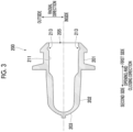
- Fig. 1 is a sectional view showing an example of a configuration of a blow core 1 that is applied to an intermediate mold included in a mold unit according to a first embodiment.
- a state where the blow core 1 is viewed from an upper side in an up-down direction toward a lower side is shown. Therefore, the front side of the drawing of Fig. 1 is the upper side in the up-down direction, and the back side of the drawing is the lower side in the up-down direction.
- Fig. 2 is a sectional view showing an example of a configuration of an injection core 100 that is applied to the intermediate mold included in the mold unit according to the first embodiment.
- the blow core 1 shown in Fig. 1 is one of molds that are applied to the intermediate mold of the mold unit that performs injection blow molding.
- the intermediate mold to which the blow core 1 is applied is a mold that is disposed between a stationary side mold (not shown) and a movable side mold and that has a rotating frame.
- the injection blow molding refers to a molding method in which injection molding and blow molding are performed in two stages. The injection molding is performed in a state where the stationary side mold and the intermediate mold are mold-closed. In addition, the blow molding is performed in a state where the movable side mold and the intermediate mold are mold-closed.
- a preform 200 that is an intermediate molding product is molded in a state where the stationary side mold and the injection core 100 of the intermediate mold shown in Fig. 2 are mold-closed.
- the injection-molded preform 200 is rotationally moved to a position where the second-stage molding is performed in a state of being gripped by the rotating frame.
- high-pressure air is blown into the inside of the preform 200 in a state where the blow core 1 of the intermediate mold shown in Fig. 1 and the movable side mold are mold-closed, so that the preform 200 is stretched to mold a final molding product.
- a method of blowing air into the inside of the preform 200 in the blow molding for example, a method of causing a stretching rod (not shown) that can output the high-pressure air to protrude into the preform can be given.
- Fig. 1 a state is shown where the injection-molded preform 200 is fitted to the blow core 1 of the intermediate mold in order to be blow-molded.
- An axial direction of the preform 200 when the preform 200 is fitted to the blow core 1 is a left-right direction in the drawing, and is the same direction as a direction in which the intermediate mold to which the blow core 1 is applied and the movable side mold are opened and closed for the blow molding.
- each of a direction in which the intermediate mold to which the blow core 1 is applied and the movable side mold are opened and closed (the left-right direction in the drawing of Fig. 1 ) and a direction in which the intermediate mold to which the injection core 100 is applied and the stationary side mold are opened and closed (the left-right direction in the drawing of Fig. 2 ) is referred to as an "opening and closing direction".
- the right side of the drawing in the opening and closing direction is referred to as a "first side”
- the left side of the drawing in the opening and closing direction is referred to as a "second side”.
- each of a direction (the up-down direction in the drawing of Fig.
- each of a side of a center axis (shown by one-dot chain line) in the radial direction of the preform 200 and a side of a center axis (shown by one-dot chain line) in the radial direction of the injection core 100 is referred to as an "inside", and an opposite side is referred to as an "outside”.
- the preform 200 which is a blow molding target includes a mouth portion 201, a main body 202, and a bottom portion 203.
- the mouth portion 201, the main body 202, and the bottom portion 203 in the preform 200 are portions of the shape of the preform 200 having continuity, and there is no clear boundary.
- a portion on the first side in the opening and closing direction with respect to a fringe 204 which is a portion protruding toward the outside in the preform 200 is defined as the mouth portion 201, and a portion near an end portion on the second side in the opening and closing direction of the preform 200 is defined as the bottom portion 203.
- a portion of the preform 200 other than the mouth portion 201 and the bottom portion 203 is defined as the main body 202.
- the fringe 204 is set to be included in the mouth portion 201.
- the blow core 1 has at least a protrusion 11 that is fitted into a blowing port 205 formed in the mouth portion 201 of the preform 200, and a through-hole 12 through which a stretching rod (not shown) that is inserted into the preform 200 penetrates.
- the protrusion 11 is a cylindrical protrusion that protrudes toward the second side in the opening and closing direction of the blow core 1.
- An outer surface 111 in the radial direction of the protrusion 11 is configured as a smooth surface that slidably supports an inner surface 211 of the mouth portion 201 of the preform 200, and also functions as a mold that molds at least a part of the surface 211.
- An annular protrusion 212 molded during the injection molding is formed on the inner surface 211 of the mouth portion 201 of the preform 200.
- the protrusion 212 is a protrusion formed on the inner surface 211 in a thick portion of the preform 200, and is a protrusion that is intentionally molded during the injection molding. That is, a recessed portion 101 is intentionally formed in the injection core 100 of Fig. 2 .
- the recessed portion 101 is filled with molten resin during the injection molding, so that the protrusion 212 of Fig. 1 is molded.
- the reason why the protrusion 212 is intentionally molded during the injection molding is to prevent a recessed portion as a molding defect from being formed in the preform 200.
- the recessed portion as a molding defect that is formed on the inner surface 211 of the preform 200 will be described with reference to Fig. 3 .
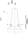
- Fig. 3 is a diagram showing a specific example in a case where a recessed portion 213 as a molding defect is formed in the preform 200 that is an intermediate molding product.
- the protrusion 212 (refer to Fig. 1 ) is formed in the thick portion of the injection-molded preform 200. In this way, the recessed portion 213 as a molding defect is prevented from being formed on the inner surface 211 of the preform 200.
- the protrusion 212 is not formed on the inner surface 211 of the preform 200, as shown in Fig. 3 , there is a case where the recessed portion 213 as a molding defect is formed on the inner surface 211 of the thick portion of the preform 200. This is because the volume shrinkage rate due to the cooling of the thick portion of the preform 200 is higher than the volume shrinkage rate due to the cooling of the thin portion.
- the thickness of the preform 200 may be set to such a thickness that the inner surface 211 of the preform 200 is smoothed at a stage where the preform 200 is injection-molded.
- the preforms 200 that are injection-molded have individual differences, it is difficult to accurately predict the shape or size of the recessed portion 213 that may be formed in each preform 200.
- the recessed portion 213 may be formed on the inner surface 211 of the thick portion of the preform 200, or the recessed portion 213 may not be formed depending on the molding conditions.
- an unintended protrusion may be formed on the inner surface 211 of the preform 200 due to some factor.
- the mold for injection molding is configured to necessarily form the protrusion 212 on the inner surface 211 of the preform 200.
- the shape or size of the protrusion 212 that is formed in the preform 200 is not particularly limited, and for example, the shape or size of the protrusion 212 is designed by predicting to some extent the shape or size of the recessed portion 213 that can be formed in a case where the protrusion 212 is not formed in the preform 200. Then, the shape of the recessed portion 101 of the injection core 100 in Fig. 2 is designed in accordance with the shape or size of the designed protrusion 212.
- the prediction of the shape or size of the recessed portion 213 is performed based on information on past molding results or prototypes, or the like. However, it is only necessary that the protrusion 212 having a size that can be crushed by the tip portion 112 of the protrusion 11 of the blow core 1 when the preform 200 is fitted to the blow core 1 is formed. Therefore, it is not necessary to accurately predict the shape or size of the recessed portion 213 that can be formed in a case where the protrusion 212 is not formed in the preform 200.
- Fig. 5 is a diagram showing a specific example of a bottle container 400 that is a final molding product molded by the blow molding.
- the bottle container 400 as a final molding product is molded.
- a position 500 indicated by a broken line at a mouth portion 401 of the bottle container 400 shown in Fig. 5 indicates a position where the protrusion 212 (refer to Fig. 1 ) of the preform 200 is formed.
- the position 500 is a smooth surface because it is crushed by the blow core 1 (refer to Fig. 4 ).
- the mold unit to which the present invention is applied can take various embodiments with the following configurations.
- the mold unit according to the first embodiment is a mold unit in which the injection core 100, which is a first mold for performing injection molding that molds the preform 200 that is an intermediate molding product, molds the protrusion 212 on the inner surface 211 of a thick portion of the preform 200, and when the preform 200 is fitted to the blow core 1 that is a second mold in order to perform blow molding that molds a final molding product from the preform 200, the blow core 1 crushes the protrusion 212 from an inside of the preform 200.
- the injection core 100 which is a first mold for performing injection molding that molds the preform 200 that is an intermediate molding product
- the protrusion 212 is molded on the inner surface 211 of the thick portion of the preform 200 by the injection molding. Then, when the preform 200 is fitted to the blow core 1 in order to perform the blow molding, the blow core 1 crushes the protrusion 212 from the inside of the preform 200. As a result, the inner surface 211 of the preform 200 can be smoothed in the operation of the related art in which the preform 200 is fitted to the blow core 1 in order to perform the blow molding, without extending a holding pressure time.
- the blow core 1 may crush the protrusion 212 while sliding on the inner surface 211 of the preform 200.
- the blow core 1 crushes the protrusion 212 while sliding on the inner surface 211 of the preform 200.
- the inner surface 211 of the preform 200 can be smoothed in the operation of the related art in which the blow core 1 is slid on the inner surface 211 of the preform 200.
- the shape of the protrusion 212 may be a shape in which at least a protrusion is formed even though the shape of the preform 200 changes after the injection molding is performed (for example, even though the volume is contracted due to cooling).
- the shape of the protrusion 212 is designed such that at least a protrusion is formed by a change in the shape of the preform 200 after the injection molding is performed.
- the protrusion 212 is necessarily formed on the inner surface 211 of the thick portion of the preform 200 when the preform 200 is fitted to the blow core 1, the surface 211 can be smoothed.
- the mold unit may include a stationary side mold, an intermediate mold, and a movable side mold, in which the injection molding is performed in a state where the stationary side mold and the intermediate mold having the injection core 100 as the first mold are mold-closed, and the blow molding is performed in a state where the intermediate mold having the blow core 1 as the second mold and the movable side mold are mold-closed.
- Figs. 6A and 6B are sectional views showing an example of a configuration of a blow core 2 that is applied to an intermediate mold included in a mold unit according to a second embodiment.
- Figs. 6A and 6B a state where the blow core 2 is viewed from the upper side in the up-down direction toward the lower side is shown. Therefore, the front side of the drawing in Figs. 6A and 6B is the upper side in the up-down direction, and the back side of the drawing is the lower side in the up-down direction.
- the blow core 2 shown in Figs. 6A and 6B is one of the molds that are applied to the intermediate mold included in the mold unit for performing the injection blow molding, as in the first embodiment described above.
- the intermediate mold to which the blow core 2 is applied is a mold disposed between a stationary side mold (not shown) and a movable side mold 60, and is a mold having a rotating frame.
- Fig. 6A a state where the injection-molded preform 200 has been inserted into the blow core 2 of the intermediate mold in order to be blow-molded is shown.
- the axial direction of the preform 200 inserted into the blow core 2 is the left-right direction in the drawing, and is the same direction as the direction in which the intermediate mold to which the blow core 2 is applied and the movable side mold are opened and closed for blow molding.
- a difference between the first embodiment and the second embodiment is that the protrusion 31 of the blow core 2 according to the second embodiment is longer toward the second side in the opening and closing direction than the protrusion 11 (refer to Fig. 1 ) of the blow core 1 according to the first embodiment.
- the protrusion 31 of the blow core 2 has a shape that is long to an extent that a part thereof is inserted into the inside of the movable side mold 60 which is located on the second side in the opening and closing direction with respect to the blow core 2.
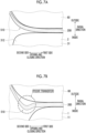
- Figs. 7A and 7B are enlarged views of the difficult-to-transfer portion 510 shown in Fig. 6A described above.
- the mold unit according to the second embodiment of the present invention is a mold unit in which, when the preform 200, which is an intermediate molding product molded by injection molding by the injection core 100 that is a first mold, is fitted to the blow core 2 that is a second mold that performs blow molding for molding a final molding product, a tip portion 312 of the protrusion 31 that is a part of the blow core 2 presses the difficult-to-transfer portion 510, which is a difficult-to-stretch portion, from an inside of the preform 200.
- the tip portion 312 of the protrusion 31, which is a part of the blow core 2 presses the difficult-to-transfer portion 510, which is a difficult-to-stretch portion, from the inside of the preform 200.
- the difficult-to-transfer portion 510 is pushed toward the movable side mold 60. Therefore, the transfer is easily performed, and poor transfer is suppressed.
- the tip portion 312 of the protrusion 31, which is a part of the blow core 2 that presses the difficult-to-transfer portion 510, is disposed at a position where the difficult-to-transfer portion 510 can be pressed inside the preform 200.
- the difficult-to-transfer portion 510 is pushed toward the movable side mold 60, so that the difficult-to-transfer portion 510 is easily transferred, and poor transfer is suppressed.
- the mold unit may include a stationary side mold, the movable side mold 60, and an intermediate mold, in which the injection molding is performed in a state where the stationary side mold and the intermediate mold having the injection core 100 as the first mold are mold-closed, and the blow molding is performed in a state where the movable side mold 60 and the intermediate mold having the blow core 2 as the second mold are mold-closed.
- the tip portion 312 of the protrusion 31, which is a part of the blow core 2 presses the difficult-to-transfer portion 510, which is a difficult-to-stretch portion, from the inside of the preform 200.
- the difficult-to-transfer portion 510 is pushed toward the movable side mold 60, so that the difficult-to-transfer portion 510 is easily transferred, and poor transfer is suppressed.
- the blow core 2 that is applied to the intermediate mold included in the mold unit according to the second embodiment has basically the same configuration as the blow core 1 that is applied to the intermediate mold included in the mold unit according to the first embodiment described above.
- the length toward the second side in the opening and closing direction of the portion of the protrusion 31 of the blow core 2, which can be inserted into the preform 200 is longer than the length toward the second side in the opening and closing direction of the portion of the protrusion 11 of the blow core 1 that can be inserted into the preform 200.
- the second embodiment is more likely to suppress the occurrence of poor transfer in the difficult-to-transfer portion 510 than the first embodiment.
- the present invention is not limited to the embodiments described above. Further, the effects of the present invention are also not limited to those described in the embodiments described above.
- the configurations of the blow core 1 shown in Figs. 1 and 4 , the injection core 100 shown in Fig. 2 , and the blow core 2 shown in Figs. 6A and 6B are merely examples for achieving the object of the present invention, and are not particularly limited.
- the final molding product is the bottle container 400.
- the final molding product does not need to be a bottle container.
- the final molding product may be any molding product molded via the injection blow molding.
- the final molding product does not need to be a molding product molded by the injection blow molding. Since the molding of the intermediate molding product and the molding of the final molding product may be performed by using different molds, for example, a molding product molded by so-called two-color molding in which different resins or materials are combined and integrated, or a molding product molded by so-called insert molding in which an insert product such as a metal screw or a terminal is inserted into a mold in advance and molten resin is injected around the insert product to be integrally molded may be the final molding product.
- a molding product molded by so-called two-color molding in which different resins or materials are combined and integrated
- a molding product molded by so-called insert molding in which an insert product such as a metal screw or a terminal is inserted into a mold in advance and molten resin is injected around the insert product to be integrally molded may be the final molding product.
Landscapes
- Engineering & Computer Science (AREA)
- Manufacturing & Machinery (AREA)
- Mechanical Engineering (AREA)
- Physics & Mathematics (AREA)
- Geometry (AREA)
- Moulds For Moulding Plastics Or The Like (AREA)
- Processing And Handling Of Plastics And Other Materials For Molding In General (AREA)
- Blow-Moulding Or Thermoforming Of Plastics Or The Like (AREA)
Abstract
Formation of a recessed portion (101, 213) as a molding defect in a thick portion of an intermediate molding product is suppressed without extending a holding pressure time. An injection core (100) that is a first mold for performing injection molding that molds a preform (200), which is an intermediate molding product, molds a protrusion (11, 31, 212) on an inner surface (211) of a thick portion of the preform (200), and when the preform (200) is fitted to a blow core (1, 2), which is a second mold, in order to perform blow molding that molds a final molding product from the preform (200), the blow core (1, 2) crushes the protrusion (11, 31, 212) from an inside of the preform (200).
Description
- The present invention relates to a mold unit.
- In injection blow molding that is a molding method in which injection molding and blow molding are performed in two stages, a preform that is an intermediate molding product is molded via the injection molding, and a product such as a container is molded by blowing air into the inside of the preform and stretching the preform via the blow molding (for example,
Japanese Patent No. 4425750 - The preform, which is an injection-molded intermediate molding product, has a thick portion and a thin portion. Since a volume shrinkage rate due to cooling is different between the thick portion and the thin portion, there is a case where a recessed portion as a molding defect is formed in the thick portion in which the volume shrinkage rate is high. In order to supplement the volume shrinkage in the recessed portion, as so-called holding pressure, molten resin can be pumped in by applying pressure from a cylinder side. However, in a case where the thick portion is located at a position far from a gate side into which the molten resin is injected, it is necessary to extend a holding pressure time in order to make the holding pressure more effective. As a result, a molding cycle may become long.
- An object of the present invention is to suppress forming of a recessed portion as a molding defect in a thick portion of an intermediate molding product without extending a holding pressure time.
- In order to achieve such an object, according to an aspect of the present invention, there is provided a mold unit in which a first mold that performs injection molding for molding an intermediate molding product molds a protrusion on an inner surface of a thick portion of the intermediate molding product, and when the intermediate molding product is fitted to a second mold in order to perform blow molding for molding a final molding product from the intermediate molding product, the second mold crushes the protrusion from an inside of the intermediate molding product.
- Here, the second mold may crush the protrusion while sliding on an inner surface of the intermediate molding product.
- In addition, the shape of the protrusion may be a shape in which at least a protrusion is formed even though the shape of the intermediate molding product changes after the injection molding is performed.
- In addition, according to another aspect of the present invention, there is provided a mold unit in which, when an intermediate molding product molded by injection molding using a first mold is fitted to a second mold that performs blow molding for molding a final molding product, a part of the second mold presses a difficult-to-stretch portion from an inside of the intermediate molding product.
- In addition, a part of the second mold may be disposed at a position where the difficult-to-stretch portion is capable of being pressed inside the intermediate molding product.
- In addition, the mold unit may include a stationary side mold, an intermediate mold, and a movable side mold, in which the injection molding is performed in a state where the stationary side mold and the intermediate mold having an injection core as the first mold are mold-closed, and the blow molding is performed in a state where the intermediate mold having a blow core as the second mold and the movable side mold are mold-closed.
- According to the present invention, it is possible to suppress forming of a recessed portion as a molding defect in a thick portion of the intermediate molding product without extending a holding pressure time.
-
-
Fig. 1 is a sectional view showing an example of a configuration of a blow core that is applied to an intermediate mold included in a mold unit according to a first embodiment. -
Fig. 2 is a sectional view showing an example of a configuration of an injection core that is applied to the intermediate mold included in the mold unit according to the first embodiment. -
Fig. 3 is a diagram showing a specific example in a case where a recessed portion as a molding defect is formed in a preform that is an intermediate molding product. -
Fig. 4 is a sectional view showing an example of a state where the preform is fitted to the blow core. -
Fig. 5 is a diagram showing a specific example of a bottle container that is a final molding product molded by blow molding. -
Figs. 6A and 6B are sectional views showing an example of a configuration of a blow core that is applied to an intermediate mold included in a mold unit according to a second embodiment. -
Figs. 7A and 7B are enlarged views of a difficult-to-transfer portion. - Hereinafter, embodiments of the present invention will be described in detail with reference to the accompanying drawings.
-
Fig. 1 is a sectional view showing an example of a configuration of ablow core 1 that is applied to an intermediate mold included in a mold unit according to a first embodiment. InFig. 1 , a state where theblow core 1 is viewed from an upper side in an up-down direction toward a lower side is shown. Therefore, the front side of the drawing ofFig. 1 is the upper side in the up-down direction, and the back side of the drawing is the lower side in the up-down direction. -
Fig. 2 is a sectional view showing an example of a configuration of aninjection core 100 that is applied to the intermediate mold included in the mold unit according to the first embodiment. - The
blow core 1 shown inFig. 1 is one of molds that are applied to the intermediate mold of the mold unit that performs injection blow molding. The intermediate mold to which theblow core 1 is applied is a mold that is disposed between a stationary side mold (not shown) and a movable side mold and that has a rotating frame. The injection blow molding refers to a molding method in which injection molding and blow molding are performed in two stages. The injection molding is performed in a state where the stationary side mold and the intermediate mold are mold-closed. In addition, the blow molding is performed in a state where the movable side mold and the intermediate mold are mold-closed. - In the injection blow molding, first, in the injection molding that is the first-stage molding, a
preform 200 that is an intermediate molding product is molded in a state where the stationary side mold and theinjection core 100 of the intermediate mold shown inFig. 2 are mold-closed. The injection-moldedpreform 200 is rotationally moved to a position where the second-stage molding is performed in a state of being gripped by the rotating frame. Next, in the blow molding that is the second-stage molding, high-pressure air is blown into the inside of thepreform 200 in a state where theblow core 1 of the intermediate mold shown inFig. 1 and the movable side mold are mold-closed, so that thepreform 200 is stretched to mold a final molding product. As a method of blowing air into the inside of thepreform 200 in the blow molding, for example, a method of causing a stretching rod (not shown) that can output the high-pressure air to protrude into the preform can be given. - In
Fig. 1 , a state is shown where the injection-moldedpreform 200 is fitted to theblow core 1 of the intermediate mold in order to be blow-molded. An axial direction of thepreform 200 when thepreform 200 is fitted to theblow core 1 is a left-right direction in the drawing, and is the same direction as a direction in which the intermediate mold to which theblow core 1 is applied and the movable side mold are opened and closed for the blow molding. - Hereinafter, each of a direction in which the intermediate mold to which the
blow core 1 is applied and the movable side mold are opened and closed (the left-right direction in the drawing ofFig. 1 ) and a direction in which the intermediate mold to which theinjection core 100 is applied and the stationary side mold are opened and closed (the left-right direction in the drawing ofFig. 2 ) is referred to as an "opening and closing direction". Furthermore, the right side of the drawing in the opening and closing direction is referred to as a "first side", and the left side of the drawing in the opening and closing direction is referred to as a "second side". In addition, each of a direction (the up-down direction in the drawing ofFig. 1 ) perpendicular to the axial direction (the opening and closing direction) of thepreform 200 when thepreform 200 is inserted into theblow core 1 and a direction (the up-down direction in the drawing ofFig. 2 ) perpendicular to the axial direction (the opening and closing direction) of theinjection core 100 is referred to as a "radial direction". Furthermore, each of a side of a center axis (shown by one-dot chain line) in the radial direction of thepreform 200 and a side of a center axis (shown by one-dot chain line) in the radial direction of theinjection core 100 is referred to as an "inside", and an opposite side is referred to as an "outside". - As shown in
Fig. 1 , thepreform 200 which is a blow molding target includes amouth portion 201, amain body 202, and abottom portion 203. Themouth portion 201, themain body 202, and thebottom portion 203 in thepreform 200 are portions of the shape of thepreform 200 having continuity, and there is no clear boundary. For this reason, in the present embodiment, a portion on the first side in the opening and closing direction with respect to afringe 204 which is a portion protruding toward the outside in thepreform 200 is defined as themouth portion 201, and a portion near an end portion on the second side in the opening and closing direction of thepreform 200 is defined as thebottom portion 203. In addition, a portion of thepreform 200 other than themouth portion 201 and thebottom portion 203 is defined as themain body 202. Thefringe 204 is set to be included in themouth portion 201. - The
blow core 1 has at least aprotrusion 11 that is fitted into a blowingport 205 formed in themouth portion 201 of thepreform 200, and a through-hole 12 through which a stretching rod (not shown) that is inserted into thepreform 200 penetrates. Theprotrusion 11 is a cylindrical protrusion that protrudes toward the second side in the opening and closing direction of theblow core 1. Anouter surface 111 in the radial direction of theprotrusion 11 is configured as a smooth surface that slidably supports aninner surface 211 of themouth portion 201 of thepreform 200, and also functions as a mold that molds at least a part of thesurface 211. - An
annular protrusion 212 molded during the injection molding is formed on theinner surface 211 of themouth portion 201 of thepreform 200. Theprotrusion 212 is a protrusion formed on theinner surface 211 in a thick portion of thepreform 200, and is a protrusion that is intentionally molded during the injection molding. That is, arecessed portion 101 is intentionally formed in theinjection core 100 ofFig. 2 . Therecessed portion 101 is filled with molten resin during the injection molding, so that theprotrusion 212 ofFig. 1 is molded. The reason why theprotrusion 212 is intentionally molded during the injection molding is to prevent a recessed portion as a molding defect from being formed in thepreform 200. The recessed portion as a molding defect that is formed on theinner surface 211 of thepreform 200 will be described with reference toFig. 3 . -
Fig. 3 is a diagram showing a specific example in a case where arecessed portion 213 as a molding defect is formed in thepreform 200 that is an intermediate molding product. - In the present embodiment, the protrusion 212 (refer to
Fig. 1 ) is formed in the thick portion of the injection-moldedpreform 200. In this way, the recessedportion 213 as a molding defect is prevented from being formed on theinner surface 211 of thepreform 200. On the other hand, in a case where theprotrusion 212 is not formed on theinner surface 211 of thepreform 200, as shown inFig. 3 , there is a case where the recessedportion 213 as a molding defect is formed on theinner surface 211 of the thick portion of thepreform 200. This is because the volume shrinkage rate due to the cooling of the thick portion of thepreform 200 is higher than the volume shrinkage rate due to the cooling of the thin portion. - Since a high accuracy is required for the inner diameter of the
mouth portion 201 of thepreform 200, when the recessedportion 213 is formed on the inside of themouth portion 201, the final molding product is highly likely to be treated as a defective product. Although themain body 202 also has a thick portion, in the first embodiment, an object is to suppress the forming of the recessedportion 213 on the inner side of the thick portion of themouth portion 201 where particularly high accuracy is required. For this reason, for example, the suppression of a molding defect (for example, poor transfer to be described later) that may occur in the thick portion (a portion indicated by a broken line inFig. 1 ) of themain body 202 is not a target of an object of the first embodiment, and is an object of a second embodiment to be described later. -
Fig. 4 is a sectional view showing an example of a state where thepreform 200 is fitted to theblow core 1. - The
preform 200 is fitted to theblow core 1 before the start of the blow molding. Specifically, thepreform 200 is fitted to theblow core 1 by using a rotating frame (not shown). InFig. 4 , a state where the blowingport 205 of thepreform 200 is fitted to theprotrusion 11 of theblow core 1 is shown. Theinner surface 211 of themouth portion 201 of thepreform 200 slides on theouter surface 111 in the radial direction of theprotrusion 11 of theblow core 1 when the blowingport 205 is fitted to theprotrusion 11. In this case, atip portion 112 of theprotrusion 11 of theblow core 1 crushes the protrusion 212 (refer toFig. 1 ) of thesurface 211 of thepreform 200 in accordance with the sliding of thesurface 211 of thepreform 200. In this way, as shown inFig. 4 , theinner surface 211 in the radial direction of thepreform 200 is smoothed. - Here, in a case where the shape or size of the recessed portion 213 (refer to
Fig. 3 ) as a molding defect, which is formed in thepreform 200, can be accurately predicted, the thickness of thepreform 200 may be set to such a thickness that theinner surface 211 of thepreform 200 is smoothed at a stage where thepreform 200 is injection-molded. However, since thepreforms 200 that are injection-molded have individual differences, it is difficult to accurately predict the shape or size of the recessedportion 213 that may be formed in eachpreform 200. In addition, as in the example ofFig. 3 , the recessedportion 213 may be formed on theinner surface 211 of the thick portion of thepreform 200, or the recessedportion 213 may not be formed depending on the molding conditions. In addition, in some cases, an unintended protrusion may be formed on theinner surface 211 of thepreform 200 due to some factor. - On the other hand, in the present embodiment, the mold for injection molding is configured to necessarily form the
protrusion 212 on theinner surface 211 of thepreform 200. The shape or size of theprotrusion 212 that is formed in thepreform 200 is not particularly limited, and for example, the shape or size of theprotrusion 212 is designed by predicting to some extent the shape or size of the recessedportion 213 that can be formed in a case where theprotrusion 212 is not formed in thepreform 200. Then, the shape of the recessedportion 101 of theinjection core 100 inFig. 2 is designed in accordance with the shape or size of the designedprotrusion 212. - The prediction of the shape or size of the recessed
portion 213 is performed based on information on past molding results or prototypes, or the like. However, it is only necessary that theprotrusion 212 having a size that can be crushed by thetip portion 112 of theprotrusion 11 of theblow core 1 when thepreform 200 is fitted to theblow core 1 is formed. Therefore, it is not necessary to accurately predict the shape or size of the recessedportion 213 that can be formed in a case where theprotrusion 212 is not formed in thepreform 200. -
Fig. 5 is a diagram showing a specific example of abottle container 400 that is a final molding product molded by the blow molding. - When the blow molding is performed after the
preform 200 is fitted to theblow core 1 by the method shown inFig. 4 , for example, as shown inFig. 5 , thebottle container 400 as a final molding product is molded. Aposition 500 indicated by a broken line at amouth portion 401 of thebottle container 400 shown inFig. 5 indicates a position where the protrusion 212 (refer toFig. 1 ) of thepreform 200 is formed. Theposition 500 is a smooth surface because it is crushed by the blow core 1 (refer toFig. 4 ). - In summary, the mold unit to which the present invention is applied can take various embodiments with the following configurations.
- That is, the mold unit according to the first embodiment is a mold unit in which the
injection core 100, which is a first mold for performing injection molding that molds thepreform 200 that is an intermediate molding product, molds theprotrusion 212 on theinner surface 211 of a thick portion of thepreform 200, and when thepreform 200 is fitted to theblow core 1 that is a second mold in order to perform blow molding that molds a final molding product from thepreform 200, theblow core 1 crushes theprotrusion 212 from an inside of thepreform 200. - Accordingly, the
protrusion 212 is molded on theinner surface 211 of the thick portion of thepreform 200 by the injection molding. Then, when thepreform 200 is fitted to theblow core 1 in order to perform the blow molding, theblow core 1 crushes theprotrusion 212 from the inside of thepreform 200. As a result, theinner surface 211 of thepreform 200 can be smoothed in the operation of the related art in which thepreform 200 is fitted to theblow core 1 in order to perform the blow molding, without extending a holding pressure time. - Here, the
blow core 1 may crush theprotrusion 212 while sliding on theinner surface 211 of thepreform 200. - Accordingly, the
blow core 1 crushes theprotrusion 212 while sliding on theinner surface 211 of thepreform 200. As a result, when thepreform 200 is fitted to theblow core 1 in order to perform the blow molding, theinner surface 211 of thepreform 200 can be smoothed in the operation of the related art in which theblow core 1 is slid on theinner surface 211 of thepreform 200. - In addition, the shape of the
protrusion 212 may be a shape in which at least a protrusion is formed even though the shape of thepreform 200 changes after the injection molding is performed (for example, even though the volume is contracted due to cooling). - Accordingly, the shape of the
protrusion 212 is designed such that at least a protrusion is formed by a change in the shape of thepreform 200 after the injection molding is performed. As a result, since theprotrusion 212 is necessarily formed on theinner surface 211 of the thick portion of thepreform 200 when thepreform 200 is fitted to theblow core 1, thesurface 211 can be smoothed. - In addition, the mold unit may include a stationary side mold, an intermediate mold, and a movable side mold, in which the injection molding is performed in a state where the stationary side mold and the intermediate mold having the
injection core 100 as the first mold are mold-closed, and the blow molding is performed in a state where the intermediate mold having theblow core 1 as the second mold and the movable side mold are mold-closed. - Accordingly, in the mold unit, the injection molding is performed in a state where the stationary side mold and the intermediate mold having the
injection core 100 as the first mold are mold-closed, so that theprotrusion 212 is molded on theinner surface 211 of the thick portion of thepreform 200. Then, when thepreform 200 is fitted to theblow core 1 in order to perform the blow molding in a state where the intermediate mold having theblow core 1 as the second mold and the movable side mold are mold-closed, theblow core 1 crushes theprotrusion 212 from the inside of thepreform 200. As a result, theinner surface 211 of thepreform 200 can be smoothed in the operation of the related art in which thepreform 200 is fitted to theblow core 1 in order to perform the blow molding, without extending a holding pressure time. -
Figs. 6A and 6B are sectional views showing an example of a configuration of ablow core 2 that is applied to an intermediate mold included in a mold unit according to a second embodiment. InFigs. 6A and 6B , a state where theblow core 2 is viewed from the upper side in the up-down direction toward the lower side is shown. Therefore, the front side of the drawing inFigs. 6A and 6B is the upper side in the up-down direction, and the back side of the drawing is the lower side in the up-down direction. - The
blow core 2 shown inFigs. 6A and 6B is one of the molds that are applied to the intermediate mold included in the mold unit for performing the injection blow molding, as in the first embodiment described above. In addition, the intermediate mold to which theblow core 2 is applied is a mold disposed between a stationary side mold (not shown) and amovable side mold 60, and is a mold having a rotating frame. - In
Fig. 6A , a state where the injection-moldedpreform 200 has been inserted into theblow core 2 of the intermediate mold in order to be blow-molded is shown. The axial direction of thepreform 200 inserted into theblow core 2 is the left-right direction in the drawing, and is the same direction as the direction in which the intermediate mold to which theblow core 2 is applied and the movable side mold are opened and closed for blow molding. - The
blow core 2 has at least aprotrusion 31 that is fitted into the blowingport 205 formed in themouth portion 201 of thepreform 200, and a through-hole 32 through which a stretchingrod 40 that is inserted into thepreform 200 penetrates. Theprotrusion 31 is a cylindrical protrusion that protrudes toward the second side in the opening and closing direction of theblow core 2. Anouter surface 311 of theprotrusion 31 is configured to be a smooth surface that slidably supports theinner surface 211 of themouth portion 201 of thepreform 200, and also functions as a mold that molds at least a part of thesurface 211. A difference between the first embodiment and the second embodiment is that theprotrusion 31 of theblow core 2 according to the second embodiment is longer toward the second side in the opening and closing direction than the protrusion 11 (refer toFig. 1 ) of theblow core 1 according to the first embodiment. Specifically, theprotrusion 31 of theblow core 2 has a shape that is long to an extent that a part thereof is inserted into the inside of themovable side mold 60 which is located on the second side in the opening and closing direction with respect to theblow core 2. - During the blow molding, the
main body 202 and thebottom portion 203 of thepreform 200 are stretched by the high-pressure air output from the stretchingrod 40 shown inFig. 6B , and the shape of themovable side mold 60 is transferred thereto. Then, thebottle container 400, which is a final molding product, is molded. However, the main body 202 (refer toFig. 6A ) of thepreform 200 has a portion (hereinafter, referred to as a "difficult-to-transfer portion 510") to which the shape of the mold is difficult to be transferred during the blow molding. The difficult-to-transfer portion 510 is, for example, a difficult-to-stretch portion or the like due to a thick thickness. Specifically, for example, with reference toFig. 1 described above, in a portion surrounded by a broken line of thepreform 200, there is a boundary portion between a portion that is substantially solidified during injection molding and a portion that is stretched as a blow molding target while maintaining a molten state. This boundary portion corresponds to the difficult-to-transfer portion 510 shown inFig. 6A . -
Figs. 7A and 7B are enlarged views of the difficult-to-transfer portion 510 shown inFig. 6A described above. -
Fig. 7A shows an enlarged view of the difficult-to-transfer portion 510 in a case where the injection molding is performed by theblow core 2 according to the second embodiment.Fig. 7B shows an enlarged view of the difficult-to-transfer portion 510 in a case where the injection molding is performed by theblow core 1 according to the first embodiment described above as a comparison target. The difficult-to-transfer portion 510 shown inFig. 7B is a thick portion of thepreform 200 indicated by a broken line inFigs. 1 and4 described above. - As shown in
Figs. 7A and 7B , theprotrusion 31 of theblow core 2 according to the second embodiment is longer toward the second side in the opening and closing direction than theprotrusion 11 of theblow core 1 according to the first embodiment. For this reason, as shown inFig. 7A , theprotrusion 31 of theblow core 2 is pushed along themovable side mold 60 located outside the difficult-to-transfer portion 510 in the radial direction. As a result, poor transfer that is a molding defect is suppressed. On the other hand, as shown inFig. 7B , the length of theprotrusion 11 of theblow core 1 toward the second side in the opening and closing direction is not a length sufficient to push the difficult-to-transfer portion 510 toward themovable side mold 60 located outside in the radial direction, and therefore, poor transfer occurs in the difficult-to-transfer portion 510. - That is, the mold unit according to the second embodiment of the present invention is a mold unit in which, when the
preform 200, which is an intermediate molding product molded by injection molding by theinjection core 100 that is a first mold, is fitted to theblow core 2 that is a second mold that performs blow molding for molding a final molding product, atip portion 312 of theprotrusion 31 that is a part of theblow core 2 presses the difficult-to-transfer portion 510, which is a difficult-to-stretch portion, from an inside of thepreform 200. - Accordingly, when the
preform 200, which is the intermediate molding product molded by theinjection core 100, is fitted to theblow core 2, thetip portion 312 of theprotrusion 31, which is a part of theblow core 2, presses the difficult-to-transfer portion 510, which is a difficult-to-stretch portion, from the inside of thepreform 200. As a result, the difficult-to-transfer portion 510 is pushed toward themovable side mold 60. Therefore, the transfer is easily performed, and poor transfer is suppressed. - Here, the
tip portion 312 of theprotrusion 31, which is a part of theblow core 2, may be disposed at a position where the difficult-to-transfer portion 510 can be pressed inside the preform 200 (for example, a position inserted into the inside of the movable side mold 60). - Accordingly, the
tip portion 312 of theprotrusion 31, which is a part of theblow core 2 that presses the difficult-to-transfer portion 510, is disposed at a position where the difficult-to-transfer portion 510 can be pressed inside thepreform 200. As a result, the difficult-to-transfer portion 510 is pushed toward themovable side mold 60, so that the difficult-to-transfer portion 510 is easily transferred, and poor transfer is suppressed. - In addition, the mold unit may include a stationary side mold, the
movable side mold 60, and an intermediate mold, in which the injection molding is performed in a state where the stationary side mold and the intermediate mold having theinjection core 100 as the first mold are mold-closed, and the blow molding is performed in a state where themovable side mold 60 and the intermediate mold having theblow core 2 as the second mold are mold-closed. - Accordingly, when the
preform 200, which is the intermediate molding product molded by theinjection core 100 of the intermediate mold, is fitted to theblow core 2 of the intermediate mold, thetip portion 312 of theprotrusion 31, which is a part of theblow core 2, presses the difficult-to-transfer portion 510, which is a difficult-to-stretch portion, from the inside of thepreform 200. As a result, the difficult-to-transfer portion 510 is pushed toward themovable side mold 60, so that the difficult-to-transfer portion 510 is easily transferred, and poor transfer is suppressed. - The
blow core 2 that is applied to the intermediate mold included in the mold unit according to the second embodiment has basically the same configuration as theblow core 1 that is applied to the intermediate mold included in the mold unit according to the first embodiment described above. However, the length toward the second side in the opening and closing direction of the portion of theprotrusion 31 of theblow core 2, which can be inserted into thepreform 200, is longer than the length toward the second side in the opening and closing direction of the portion of theprotrusion 11 of theblow core 1 that can be inserted into thepreform 200. Therefore, when thepreform 200 is fitted to theprotrusion 31 of theblow core 2, theprotrusion 31 is deeply inserted into thepreform 200, so that thetip portion 312 on the second side in the opening and closing direction of theprotrusion 31 can push the difficult-to-transfer portion 510 of thepreform 200 toward the outside in the radial direction. As a result, the second embodiment is more likely to suppress the occurrence of poor transfer in the difficult-to-transfer portion 510 than the first embodiment. - Although the embodiments of the present invention have been described above, the present invention is not limited to the embodiments described above. Further, the effects of the present invention are also not limited to those described in the embodiments described above. For example, the configurations of the
blow core 1 shown inFigs. 1 and4 , theinjection core 100 shown inFig. 2 , and theblow core 2 shown inFigs. 6A and 6B are merely examples for achieving the object of the present invention, and are not particularly limited. - In addition, in the embodiments described above, the final molding product is the
bottle container 400. However, the final molding product does not need to be a bottle container. The final molding product may be any molding product molded via the injection blow molding. - Furthermore, the final molding product does not need to be a molding product molded by the injection blow molding. Since the molding of the intermediate molding product and the molding of the final molding product may be performed by using different molds, for example, a molding product molded by so-called two-color molding in which different resins or materials are combined and integrated, or a molding product molded by so-called insert molding in which an insert product such as a metal screw or a terminal is inserted into a mold in advance and molten resin is injected around the insert product to be integrally molded may be the final molding product.
-
- 1, 2: blow core
- 11, 31: protrusion
- 12, 32: through-hole
- 40: stretching rod
- 60: movable side mold
- 100: injection core
- 200: preform
- 201: mouth portion
- 202: main body
- 203: bottom portion
- 204: fringe
- 205: blowing port
- 212: protrusion
- 400: bottle container
- 510: difficult-to-transfer portion
Claims (6)
- A mold unit in which a first mold that performs injection molding for molding an intermediate molding product (200) molds a protrusion (11, 31, 212) on an inner surface (211) of a thick portion of the intermediate molding product (200), and
when the intermediate molding product (200) is fitted to a second mold in order to perform blow molding for molding a final molding product from the intermediate molding product (200), the second mold crushes the protrusion (11, 31, 212) from an inside of the intermediate molding product (200). - The mold unit according to claim 1,
wherein the second mold crushes the protrusion (11, 31, 212) while sliding on the inner surface (211) of the intermediate molding product (200). - The mold unit according to claim 1,
wherein a shape of the protrusion (11, 31, 212) is a shape in which at least a protrusion (11, 31, 212) is formed even though a shape of the intermediate molding product (200) changes after the injection molding is performed. - A mold unit in which, when an intermediate molding product(200) molded by injection molding using a first mold is fitted to a second mold that performs blow molding for molding a final molding product, a part of the second mold presses a difficult-to-stretch portion from an inside of the intermediate molding product (200).
- The mold unit according to claim 4,
wherein a part of the second mold is disposed at a position where the difficult-to-stretch portion is capable of being pressed inside the intermediate molding product (200) . - The mold unit according to claim 1 or 4, comprising:a stationary side mold;an intermediate mold; anda movable side mold (60),wherein the injection molding is performed in a state where the stationary side mold and the intermediate mold having an injection core (100) as the first mold are mold-closed, andthe blow molding is performed in a state where the intermediate mold having a blow core (1, 2) as the second mold and the movable side mold (60) are mold-closed.
Applications Claiming Priority (1)
| Application Number | Priority Date | Filing Date | Title |
|---|---|---|---|
| JP2023222880A JP2025104802A (en) | 2023-12-28 | 2023-12-28 | Mold Equipment |
Publications (1)
| Publication Number | Publication Date |
|---|---|
| EP4578628A1 true EP4578628A1 (en) | 2025-07-02 |
Family
ID=93923031
Family Applications (1)
| Application Number | Title | Priority Date | Filing Date |
|---|---|---|---|
| EP24219428.0A Pending EP4578628A1 (en) | 2023-12-28 | 2024-12-12 | Mold unit |
Country Status (4)
| Country | Link |
|---|---|
| US (1) | US20250214295A1 (en) |
| EP (1) | EP4578628A1 (en) |
| JP (1) | JP2025104802A (en) |
| CN (1) | CN120228880A (en) |
Families Citing this family (2)
| Publication number | Priority date | Publication date | Assignee | Title |
|---|---|---|---|---|
| EP3434701A1 (en) * | 2017-07-25 | 2019-01-30 | Arkema France | Stable aqueous polymer dispersions |
| JP7285339B2 (en) | 2019-12-20 | 2023-06-01 | 信越化学工業株式会社 | Simultaneous control method for cotton bollworm and bollworm |
Citations (4)
| Publication number | Priority date | Publication date | Assignee | Title |
|---|---|---|---|---|
| US4018860A (en) * | 1974-01-15 | 1977-04-19 | Farrell Patent Company | Injection blow molding with improved cooling |
| JPS62156923A (en) * | 1985-12-28 | 1987-07-11 | Nissei Ee S B Kikai Kk | Injection blow molding method of vessel made of synthetic resin having threaded part on inside of opening part |
| JP4425750B2 (en) | 2004-04-30 | 2010-03-03 | 住友重機械工業株式会社 | Molded product gripping device |
| EP3587061A1 (en) * | 2018-06-27 | 2020-01-01 | Resilux N.V. | Preform and container adapted for accommodating an insert piece, with methods and apparatus for their production |
-
2023
- 2023-12-28 JP JP2023222880A patent/JP2025104802A/en active Pending
-
2024
- 2024-12-05 CN CN202411776980.4A patent/CN120228880A/en active Pending
- 2024-12-12 EP EP24219428.0A patent/EP4578628A1/en active Pending
- 2024-12-23 US US18/991,723 patent/US20250214295A1/en active Pending
Patent Citations (4)
| Publication number | Priority date | Publication date | Assignee | Title |
|---|---|---|---|---|
| US4018860A (en) * | 1974-01-15 | 1977-04-19 | Farrell Patent Company | Injection blow molding with improved cooling |
| JPS62156923A (en) * | 1985-12-28 | 1987-07-11 | Nissei Ee S B Kikai Kk | Injection blow molding method of vessel made of synthetic resin having threaded part on inside of opening part |
| JP4425750B2 (en) | 2004-04-30 | 2010-03-03 | 住友重機械工業株式会社 | Molded product gripping device |
| EP3587061A1 (en) * | 2018-06-27 | 2020-01-01 | Resilux N.V. | Preform and container adapted for accommodating an insert piece, with methods and apparatus for their production |
Also Published As
| Publication number | Publication date |
|---|---|
| US20250214295A1 (en) | 2025-07-03 |
| CN120228880A (en) | 2025-07-01 |
| JP2025104802A (en) | 2025-07-10 |
Similar Documents
| Publication | Publication Date | Title |
|---|---|---|
| US20250214295A1 (en) | Mold unit | |
| US6989124B2 (en) | Apparatus and method for removing a molded article from a mold | |
| US7128865B2 (en) | Apparatus and method for two stage ejection of a molded preform from a mold | |
| EP1986838B1 (en) | Apparatus for removing a molded article from a mold, and a molded article | |
| CN106414026B (en) | Manufacturing method and manufacturing device of hollow container | |
| EP3928952B1 (en) | Method for manufacturing eccentric container, and temperature adjustment mold | |
| EP3369551A1 (en) | Metal mould, blow moulding apparatus, and blow moulding method | |
| CA2545212C (en) | Mould cavity structure | |
| EP4134220A1 (en) | Delamination container manufacturing method and manufacturing device | |
| US4358420A (en) | Method of making a thin wall centrifuge tube with improved polymer properties | |
| EP4134317A1 (en) | Peeling container and method for manufacturing peeling container | |
| US20250214296A1 (en) | Operation mechanism, blow molding mechanism, split mold, and mold unit | |
| KR20180093515A (en) | Metal mold for heavy blow molded containers | |
| EP4134221A1 (en) | Method and device for manufacturing delamination container | |
| US20060292260A1 (en) | Gating structure for mold | |
| KR20250124343A (en) | Method for manufacturing a preform, a resin container, and a device for manufacturing a resin container | |
| US20060165930A1 (en) | Injection-molding process and apparatus using blow-mold resin | |
| US11325297B2 (en) | Injection molding mold, and injection molding method for hollow article | |
| JP2000084969A (en) | Shaping method, shaping mold, and shaping molded article |
Legal Events
| Date | Code | Title | Description |
|---|---|---|---|
| PUAI | Public reference made under article 153(3) epc to a published international application that has entered the european phase |
Free format text: ORIGINAL CODE: 0009012 |
|
| STAA | Information on the status of an ep patent application or granted ep patent |
Free format text: STATUS: EXAMINATION IS IN PROGRESS |
|
| 17P | Request for examination filed |
Effective date: 20241212 |
|
| AK | Designated contracting states |
Kind code of ref document: A1 Designated state(s): AL AT BE BG CH CY CZ DE DK EE ES FI FR GB GR HR HU IE IS IT LI LT LU LV MC ME MK MT NL NO PL PT RO RS SE SI SK SM TR |