EP4578567A1 - Method for manufacturing press-molded article - Google Patents
Method for manufacturing press-molded article Download PDFInfo
- Publication number
- EP4578567A1 EP4578567A1 EP23874732.3A EP23874732A EP4578567A1 EP 4578567 A1 EP4578567 A1 EP 4578567A1 EP 23874732 A EP23874732 A EP 23874732A EP 4578567 A1 EP4578567 A1 EP 4578567A1
- Authority
- EP
- European Patent Office
- Prior art keywords
- press
- formed product
- top plate
- forming
- shape
- Prior art date
- Legal status (The legal status is an assumption and is not a legal conclusion. Google has not performed a legal analysis and makes no representation as to the accuracy of the status listed.)
- Pending
Links
Images














Classifications
-
- B—PERFORMING OPERATIONS; TRANSPORTING
- B21—MECHANICAL METAL-WORKING WITHOUT ESSENTIALLY REMOVING MATERIAL; PUNCHING METAL
- B21D—WORKING OR PROCESSING OF SHEET METAL OR METAL TUBES, RODS OR PROFILES WITHOUT ESSENTIALLY REMOVING MATERIAL; PUNCHING METAL
- B21D22/00—Shaping without cutting, by stamping, spinning, or deep-drawing
- B21D22/20—Deep-drawing
- B21D22/26—Deep-drawing for making peculiarly, e.g. irregularly, shaped articles
-
- B—PERFORMING OPERATIONS; TRANSPORTING
- B21—MECHANICAL METAL-WORKING WITHOUT ESSENTIALLY REMOVING MATERIAL; PUNCHING METAL
- B21D—WORKING OR PROCESSING OF SHEET METAL OR METAL TUBES, RODS OR PROFILES WITHOUT ESSENTIALLY REMOVING MATERIAL; PUNCHING METAL
- B21D22/00—Shaping without cutting, by stamping, spinning, or deep-drawing
- B21D22/20—Deep-drawing
-
- B—PERFORMING OPERATIONS; TRANSPORTING
- B21—MECHANICAL METAL-WORKING WITHOUT ESSENTIALLY REMOVING MATERIAL; PUNCHING METAL
- B21D—WORKING OR PROCESSING OF SHEET METAL OR METAL TUBES, RODS OR PROFILES WITHOUT ESSENTIALLY REMOVING MATERIAL; PUNCHING METAL
- B21D22/00—Shaping without cutting, by stamping, spinning, or deep-drawing
- B21D22/20—Deep-drawing
- B21D22/24—Deep-drawing involving two drawing operations having effects in opposite directions with respect to the blank
-
- B—PERFORMING OPERATIONS; TRANSPORTING
- B21—MECHANICAL METAL-WORKING WITHOUT ESSENTIALLY REMOVING MATERIAL; PUNCHING METAL
- B21D—WORKING OR PROCESSING OF SHEET METAL OR METAL TUBES, RODS OR PROFILES WITHOUT ESSENTIALLY REMOVING MATERIAL; PUNCHING METAL
- B21D24/00—Special deep-drawing arrangements in, or in connection with, presses
- B21D24/005—Multi-stage presses
-
- B—PERFORMING OPERATIONS; TRANSPORTING
- B21—MECHANICAL METAL-WORKING WITHOUT ESSENTIALLY REMOVING MATERIAL; PUNCHING METAL
- B21D—WORKING OR PROCESSING OF SHEET METAL OR METAL TUBES, RODS OR PROFILES WITHOUT ESSENTIALLY REMOVING MATERIAL; PUNCHING METAL
- B21D53/00—Making other particular articles
- B21D53/88—Making other particular articles other parts for vehicles, e.g. cowlings, mudguards
Definitions
- the present invention relates to a method for manufacturing a press-formed product including at least a top plate portion, a vertical wall portion, and a ridge portion which is a connection portion between the top plate portion and the vertical wall portion.
- Patent Literature 1 In the method disclosed in Patent Literature 1, first, in a first forming step, an intermediate-shape component having a convex shape portion formed on the vertical side portion side of the connecting side portion in the top plate portion and a curved R portion obtained by raising a bottom R portion connecting the wall portion and the flange portion continuous from the connecting side portion upward is formed. Then, in the second forming step, the convex shape portion and the curved R portion of the intermediate-shape component are crushed to form a T-shaped component having a target shape. As a result, the material is allowed to flow into the wall portion continuous with the connection side portion, and the crack generated at the connection portion between the wall portion and the flange portion can be prevented.
- the inclination angle based on the transverse side portion 3a of the target shape is preferably 3 degrees or more and 25 degrees or less.
Landscapes
- Engineering & Computer Science (AREA)
- Mechanical Engineering (AREA)
- Shaping Metal By Deep-Drawing, Or The Like (AREA)
Abstract
Description
- The present invention relates to a method for manufacturing a press-formed product including at least a top plate portion, a vertical wall portion, and a ridge portion which is a connection portion between the top plate portion and the vertical wall portion.
- Under the recent carbon dioxide emission regulations, it is also necessary to reduce the weight of the vehicle body as the improvement of the collision safety of the vehicle body progresses due to the tightening of the collision safety standard of automobiles. Therefore, in order to achieve both collision safety performance and weight reduction of the vehicle body, metal sheets having higher strength than the conventional metal sheets are being adopted in the vehicle body. Ultra-high-tensile steel sheets of 1.5 GPa class or more have been applied in close proximity. However, since a metal sheet having high strength is generally poor in ductility, when a press-formed product is manufactured as a vehicle body component, cracking is likely to occur from an end portion in the process of press-forming.
- Conventionally, methods for preventing cracks in press-formed articles have been adopted. For example,
Patent Literature 1 discloses a method for preventing a crack generated at a connection portion between a wall portion continuous from a connection side portion and a flange portion continuous from the wall portion when press-forming a T-shaped component having a T-shaped top plate portion in which a vertical side portion and a transverse side portion are connected by the connection side portion. In addition, Patent Literature 2 discloses a method for preventing a crack due to stretch flange forming of a press-formed product including a flat plate portion having a recessed outer peripheral edge portion in which a part of an outer peripheral edge is recessed inward and a flange portion bent along the recessed outer peripheral edge portion. -
- Patent Literature 1:
JP 2019-13952 A - Patent Literature 2:
JP 2016-104492 A - In the method disclosed in
Patent Literature 1, first, in a first forming step, an intermediate-shape component having a convex shape portion formed on the vertical side portion side of the connecting side portion in the top plate portion and a curved R portion obtained by raising a bottom R portion connecting the wall portion and the flange portion continuous from the connecting side portion upward is formed. Then, in the second forming step, the convex shape portion and the curved R portion of the intermediate-shape component are crushed to form a T-shaped component having a target shape. As a result, the material is allowed to flow into the wall portion continuous with the connection side portion, and the crack generated at the connection portion between the wall portion and the flange portion can be prevented. - In addition, in the method disclosed in Patent Literature 2, plastic deformation is applied to a portion corresponding to the flat plate portion in the blank material, and the material is drawn into the portion subjected to the plastic deformation, so that the material is drawn to the portion corresponding to the bent portion of the flange portion, and an excess portion is applied to the portion corresponding to the bent portion. Then, the blank material applied with the excess is bend-processed to form a press-formed product having a flange portion. As a result, the formability of the bent portion in the flange portion of the press-formed product is not deteriorated, and the occurrence of stretch flange cracking can be effectively suppressed.
- As described above, the methods disclosed in
Patent Literature 1 and Patent Literature 2 prevent cracking of a portion subjected to stretch flange deformation in a press-formed product. Meanwhile, for example, in a press-formed product having a top plate portion having a substantially T-shape or a substantially L-shape in a top view and having a transverse side portion and a vertical side portion, there has been a case where a crack occurs at an end portion on a distal end side of the transverse side portion in a ridge portion connecting the vertical wall portion and the transverse side portion, unlike a crack caused by stretch flange deformation. However, in the methods disclosed inPatent Literature 1 and Patent Literature 2 described above, it is not possible to suppress cracking at the end portion of the ridge portion connecting the vertical wall portion and the transverse side portion of the press-formed product having such a top plate portion having a substantially T-shape or a substantially L-shape. - In addition, also in press-forming of a press-formed product including a top plate portion, a vertical wall portion continuous with the top plate portion via a ridge portion, and a vertical flange portion continuous with the vertical wall portion, it has been difficult to suppress a crack generated at an end portion of the ridge portion.
- Further, in press-forming of a press-formed product including a top plate portion and a vertical wall portion continuous with the top plate portion via a ridge portion, in which the top plate portion or a part thereof is curved in a top view, and the vertical wall portion is continuous inside the curve of the top plate portion, it is also difficult to suppress a crack generated at an end portion of the ridge portion.
- The present invention has been made in view of the above problems, and an object of the present invention is to provide a method for manufacturing a press-formed product which includes a top plate portion and a vertical wall portion continuous with the top plate portion via a ridge portion while suppressing occurrence of cracking during press-forming.
- To solve the above-described problem and achieve the objection, (1) a method according to the present invention for manufacturing a press-formed product including at least a top plate portion, a vertical wall portion, and a ridge portion which is a connection portion between the top plate portion and the vertical wall portion, includes: a first forming step of press-forming a metal sheet blank into an intermediate formed product including an intermediate top plate portion, an intermediate vertical wall portion, and an intermediate ridge portion connecting the intermediate top plate portion and the intermediate vertical wall portion, the intermediate formed product including a convex portion having a height higher than a reference height of a top plate surface at one position or a plurality of positions of the intermediate top plate portion including the intermediate ridge portion; and a second forming step of press-forming the intermediate formed product into the press-formed product.
- (2) In the above-described method for manufacturing the press-formed product according to the invention (1), in a shape of the press-formed product, the top plate portion includes a transverse side portion, a vertical side portion, and a connection R portion where the transverse side portion and the vertical side portion are connected to each other, the top plate portion having a substantially T-shape or a substantially L-shape in a top view, the press-formed product including: the ridge portion connected to the top plate portion from the transverse side portion of the top plate portion to the connection R portion and the vertical side portion; the vertical wall portion continuous from the transverse side portion of the top plate portion to the connection R portion and the vertical side portion via the ridge portion; and a bottom flange portion continuous from the vertical wall portion, in the first forming step, the intermediate top plate portion includes an intermediate transverse side portion, an intermediate vertical side portion, and an intermediate connection R portion where the intermediate transverse side portion and the intermediate vertical side portion are connected to each other, the intermediate top plate portion having a substantially T-shape or a substantially L-shape in a top view, and press-forming is performed to obtain the intermediate formed product in which a height of the intermediate vertical side portion of the intermediate top plate portion is lower than a height of the vertical side portion in a target product shape, and further, in the first forming step, press-forming is performed to obtain the intermediate formed product having the convex portion higher than the height of the vertical side portion at an end portion of the intermediate transverse side portion of the intermediate top plate portion including the intermediate ridge portion of the intermediate formed product and/or the intermediate connection R portion of the intermediate top plate portion including the intermediate ridge portion of the intermediate formed product.
- (3) In the above-described method for manufacturing the press-formed product according to the invention (2), in the first forming step, press-forming is performed to obtain the intermediate formed product having the convex portion whose height gradually increases toward a distal end side of the intermediate transverse side portion on the intermediate transverse side portion of the intermediate top plate portion including the intermediate ridge portion.
- (4) In the above-described method for manufacturing the press-formed product according to the invention (2), in the first forming step, press-forming is performed to obtain the intermediate formed product including the convex portion having a constant height to a distal end side of the intermediate transverse side portion on the intermediate transverse side portion of the intermediate top plate portion including the intermediate ridge portion.
- (5) In the above-described method for manufacturing the press-formed product according to the invention (2), in the first forming step, the convex portion is formed on the intermediate connection R portion including the intermediate ridge portion, and press-forming is further performed to obtain the intermediate formed product having the intermediate transverse side portion of the intermediate top plate portion having a height corresponding to the height of the convex portion of the intermediate connection R portion.
- In the above-described method for manufacturing the press-formed product according to the invention (1), in the first forming step, press-forming is performed to obtain the intermediate formed product having the convex portion higher than a reference height of the top plate surface at one position or a plurality of positions of the intermediate top plate portion including an end portion of the intermediate ridge portion.
- In the above-described method for manufacturing the press-formed product according to the invention (6), the press-formed product includes a vertical flange portion continuous with the vertical wall portion, and in the first forming step, press-forming is performed to obtain the intermediate formed product having the convex portion at an end portion of the intermediate top plate portion including the intermediate ridge portion on a vertical flange portion side in the press-formed product.
- In the above-described method for manufacturing the press-formed product according to the invention (6), the press-formed product includes the vertical wall portion in which the top plate portion or a part of the top plate portion is curved in a top view, and the vertical wall portion is continuous with an inner side of a curve of the top plate portion, and in the first forming step, press-forming is performed to obtain the intermediate formed product having the convex portion on the intermediate top plate portion including the end portion of the intermediate ridge portion.
- In the present invention, it is possible to manufacture a press-formed product having a top plate portion and a vertical wall portion continuous with the top plate portion via a ridge portion while suppressing occurrence of cracking during press-forming. In particular, in a press-formed product having a top plate portion having a substantially T-shape or a substantially L-shape in a top view and having a transverse side portion and a vertical side portion, it is possible to suppress cracking of the ridge portion on the distal end side of the transverse side portion. Further, in a press-formed product including a top plate portion, a vertical wall portion continuous with the top plate portion via a ridge portion, and a vertical flange portion continuous with the vertical wall portion, it is possible to suppress cracking of the end portion of the ridge portion close to the vertical flange side. Further, in a press-formed product including a top plate portion and a vertical wall portion continuous with the top plate portion via a ridge portion, in which the top plate portion or a part thereof is curved in a top view, and the vertical wall portion includes a vertical wall portion continuous inside the curve of the top plate portion, it is possible to suppress cracking of an end portion of the ridge portion.
-
-
FIG. 1 is a diagram for explaining an example in which a ridge portion on a transverse side distal end side and an entire top plate transverse side portion are made higher as convex portions in a method for manufacturing a press-formed product according to a first embodiment of the present invention, and illustrating a first forming step of press-forming the top plate vertical side portion into a press-formed product having an intermediate shape in which a vertical wall height is lower than a target shape, a second forming step of press-forming the top plate vertical side portion into a press-formed product having a vertical wall height of the target shape, and a reason why it is possible to suppress a crack at an end portion of the transverse side ridge portion of the press-formed product having the target shape ((a) first forming step and (b) second forming step). -
FIG. 2 is a diagram for explaining an example in which the convex portion is only the connection R portion in the method for manufacturing the press-formed product according to the first embodiment of the present invention, and illustrating a first forming step of press-forming the top plate vertical side portion into a press-formed product having an intermediate shape in which a vertical wall height is lower than a target shape, a second forming step of press-forming the top plate vertical side portion into a press-formed product having a vertical wall height of the target shape, and a reason why it is possible to suppress cracking at the end portion of the transverse side ridge portion of the press-formed product having the target shape ((a) first forming step and (b) second forming step). -
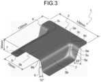
FIG. 3 is a diagram illustrating an example of a case where a roundness of a distal end of a top plate transverse side portion of a press-formed product provided with a top plate portion having a substantially T-shape in a top view, which is a target to be manufactured in the present invention, is small. -
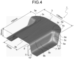
FIG. 4 is a diagram illustrating an example of a case where a roundness of a distal end of a top plate transverse side portion of a press-formed product provided with a top plate portion having a substantially T-shape in a top view, which is a target to be manufactured in the present invention, is large. -
FIG. 5 is a diagram illustrating an example of a press-formed product including a top plate portion having a substantially L-shape in a top view, which is a target to be manufactured in the present invention. -
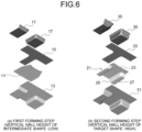
FIG. 6 is a diagram for explaining a conventional manufacturing method of press-forming a press-formed product having a substantially T-shape in a top view in two steps ((a) first forming step and (b) second forming step). -
FIG. 7 is a contour diagram illustrating a result of obtaining a sheet thickness change rate at a forming bottom dead center of each of an intermediate shape and a target shape of a substantially T-shaped press-formed product press-formed by two conventional steps ((a) intermediate shape and (b) target shape). -
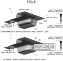
FIG. 8 is a diagram for explaining a portion where a crack occurs in a press-formed product including a top plate portion having a substantially T-shape press-formed by a conventional manufacturing method and a reason therefor. -
FIG. 9 is a diagram illustrating an example of a punch used for press-forming of a press-formed product having an intermediate shape in which a convex portion is formed on a top plate portion in a first forming step in the method for manufacturing a press-formed product according to the first embodiment of the present invention, and is a diagram illustrating a specific example of a punch in which a "convex portion" having a uniform height is formed on a ridge portion continuous from a position where a transverse side portion of the top plate portion extends, and the punch is formed into an intermediate formed product having a top plate transverse side portion having a height corresponding to the height of the convex portion. -
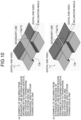
FIG. 10 is a diagram illustrating an example of a punch used for press-forming of a press-formed product having an intermediate shape in which a convex portion is formed on a top plate portion in a first forming step in the method for manufacturing a press-formed product according to the first embodiment of the present invention, and is a diagram illustrating a specific example of a punch in which a "convex portion" is formed on a ridge portion continuous from a position where the transverse side portion of the top plate portion extends so as to gradually increase in height toward a distal end portion of the ridge portion, and the punch is formed into an intermediate formed product having a top plate transverse side portion having a height corresponding to a height of the convex portion. -
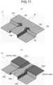
FIG. 11 is a diagram illustrating an example of a punch used for press-forming of a press-formed product having an intermediate shape in which a convex portion is formed on a top plate portion in a first forming step in the method for manufacturing a press-formed product according to the first embodiment of the present invention, and is a diagram illustrating a specific example of a punch in which a "convex portion" is formed on a joining R portion of the top plate portion. -
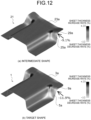
FIG. 12 is a contour diagram illustrating a result of obtaining a sheet thickness change rate at a forming bottom dead center for each of an intermediate shape and a target shape of a substantially T-shaped press-formed product press-formed by a method for manufacturing a press-formed product using a punch illustrated inFIG. 10 (a) according to the first embodiment of the present invention ((a) intermediate shape and (b) target shape). -
FIG. 13 is a contour diagram illustrating a result of obtaining a sheet thickness change rate at a forming bottom dead center for each of an intermediate shape and a target shape of a substantially T-shaped press-formed product press-formed in two conventional steps in a case where a product target shape isFIG. 4 ((a) intermediate shape and (b) target shape). -
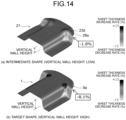
FIG. 14 is a contour diagram illustrating a result of obtaining a sheet thickness change rate at a forming bottom dead center of each of an intermediate shape and a target shape of a substantially T-shaped press-formed product press-formed by a method for manufacturing a press-formed product using a punch (convex portion) illustrated inFIG. 11 (a) according to the first embodiment of the present invention ((a) intermediate shape and (b) target shape). -
FIG. 15 is a contour diagram illustrating a result of obtaining a sheet thickness change rate at a forming bottom dead center for each of an intermediate shape and a target shape of a substantially T-shaped press-formed product press-formed by a method for manufacturing a press-formed product using a punch (convex portion + height Up of transverse side portion) illustrated inFIG. 11 (b) according to the first embodiment of the present invention ((a) intermediate shape and (b) target shape). -
FIG. 16 is a diagram illustrating a result of a sheet thickness change rate obtained for each of an intermediate shape and a target shape of a press-formed product having a top plate portion of a substantially L-shape press-formed by a conventional method ((a) intermediate shape and (b) target shape). -
FIG. 17 is a diagram illustrating a result of a sheet thickness change rate obtained for each of an intermediate shape and a target shape of a press-formed product having a substantially L-shaped top plate portion press-formed by the method according to the first embodiment of the present invention ((a) intermediate shape and (b) target shape). -
FIG. 18 is an explanatory diagram of a method for manufacturing a press-formed product according to a second embodiment of the present invention. -
FIG. 19 is an explanatory diagram of an intermediate punch used in the method for manufacturing a press-formed product according to the second embodiment of the present invention. -
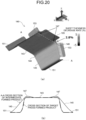
FIG. 20 is an explanatory diagram of an intermediate formed product according to the second embodiment of the present invention. -
FIG. 21 is a diagram for explaining a sheet thickness decrease rate of the press-formed product formed according to the second embodiment of the present invention. -
FIG. 22 is an explanatory diagram of another aspect of the intermediate punch according to the second embodiment of the present invention. -
FIG. 23 is an explanatory diagram of a press-formed product having a target shape according to the second embodiment of the present invention. -
FIG. 24 is an explanatory diagram of a conventional method of press-forming the press-formed product illustrated inFIG. 23 in one step. -
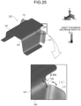
FIG. 25 is an explanatory diagram of a sheet thickness decrease rate when press-forming is performed by the conventional method illustrated inFIG. 24 . -
FIG. 26 is an explanatory diagram of a method for manufacturing a press-formed product according to a third embodiment of the present invention. -
FIG. 27 is an explanatory diagram of an intermediate punch used in the method for manufacturing a press-formed product according to the third embodiment of the present invention. -
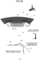
FIG. 28 is an explanatory diagram of an intermediate formed product according to the third embodiment of the present invention. -
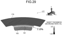
FIG. 29 is a diagram for explaining a sheet thickness decrease rate of the press-formed product formed according to the third embodiment of the present invention. -
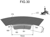
FIG. 30 is an explanatory diagram of a press-formed product having a target shape according to the third embodiment of the present invention. -
FIG. 31 is an explanatory diagram of a conventional method of press-forming the press-formed product illustrated inFIG. 30 in one step. -
FIG. 32 is an explanatory diagram of a sheet thickness decrease rate when press-forming is performed by the conventional method illustrated inFIG. 31 . -
FIG. 33 is an explanatory diagram for explaining a mechanism in which a crack occurs in a press-formed product press-formed by the conventional method illustrated inFIG. 31 . -
FIG. 34 is a diagram for explaining an inclination angle of a transverse side portion distal end side in the press-formed product having the intermediate shape in Example 1. -
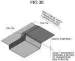
FIG. 35 is a diagram for explaining a height increment for uniformly heightening a portion on the transverse side portion distal end side in the press-formed product having the intermediate shape in Example 1. - Hereinafter, prior to the description of the method for manufacturing a press-formed product according to a first embodiment of the present invention, a press-formed product targeted in the present invention and occurrence of cracking in the press-formed product will be described. Note that the same or similar components are denoted by the same reference signs, and redundant description will be omitted.
-
FIG. 3 illustrates a press-formedproduct 1 including atop plate portion 3, avertical wall portion 5, and abottom flange portion 7 as an example of a press-formed product to be manufactured in the present invention. - As illustrated in
FIG. 3 , thetop plate portion 3 has a substantially T-shape in a top view including atransverse side portion 3a and avertical side portion 3b. Further, thetop plate portion 3 has an arc-shapedconnection R portion 3c from thetransverse side portion 3a to thevertical side portion 3b. - As illustrated in
FIG. 3 , thevertical wall portion 5 is continuous from thetransverse side portion 3a to thevertical side portion 3b of thetop plate portion 3 via aridge portion 9. Then, thevertical wall portion 5 includes a transverse sidevertical wall portion 5a continuous from thetransverse side portion 3a via a transverseside ridge portion 9a, and a vertical sidevertical wall portion 5b continuous from thevertical side portion 3b via a verticalside ridge portion 9b. Further, thevertical wall portion 5 includes a connection R-sidevertical wall portion 5c that is continuous from theconnection R portion 3c via a connection R-side ridge portion 9c and connects the transverse sidevertical wall portion 5a and the vertical sidevertical wall portion 5b. - As illustrated in
FIG. 3 , thebottom flange portion 7 is continuous from thevertical wall portion 5, and is formed continuously from each of the transverse sidevertical wall portion 5a, the vertical sidevertical wall portion 5b, and the connection R-sidevertical wall portion 5c. - Conventionally, such a press-formed
product 1 has been press-formed in two steps of a first forming step and a second forming step as illustrated inFIG. 6 . - First, in the first forming step, as illustrated in
FIG. 6 (a) , a blank 11, which is a metal sheet, is sandwiched between apunch 13 and apad 15, and adie 17 is relatively moved to thepunch 13 side to press-form a press-formed product 21 (seeFIG. 6 (b) ) having an intermediate shape having a lower vertical wall height than the target shape. Here, atop plate portion 23 of the press-formedproduct 21 having the intermediate shape is press-formed into the same shape as the top plate portion 3 (seeFIG. 3 ) of the press-formedproduct 1 having the target shape. - Then, in the subsequent second forming step, as illustrated in
FIG. 6 (b) , thetop plate portion 23 of the press-formedproduct 21 having the intermediate shape is sandwiched between apunch 31 and apad 33, and adie 35 is relatively moved to thepunch 31 side to press-form the press-formedproduct 1 having the target shape with the vertical wall height higher than that of the intermediate shape. - However, when the press-formed
product 21 having the intermediate shape is press-formed into the press-formedproduct 1 having the target shape (FIG. 3 ) in the second forming step, there has been a case where a crack is generated at an end portion of the transverseside ridge portion 9a connecting thetransverse side portion 3a and the transverse sidevertical wall portion 5a. Note that the end portion of the transverseside ridge portion 9a refers to a portion on the distal end side of the transverseside ridge portion 9a in the direction in which thetransverse side portion 3a extends. - In order to identify the cause of the occurrence of a crack at the end portion of the transverse
side ridge portion 9a of the press-formedproduct 1 including thetop plate portion 3 having such a substantially T-shape, analysis (FEM analysis) by a finite element method was performed for each step of press-forming the press-formedproduct 1 having the target shape in two steps as illustrated inFIG. 6 . -
FIG. 7 illustrates the sheet thickness change rate at the forming bottom dead center of the press-formedproduct 21 having the intermediate shape and the press-formedproduct 1 having the target shape obtained by FEM analysis for each of the first forming step and the second forming step. Note that the results illustrated inFIG. 7 illustrate a case where a steel sheet having a sheet thickness of 1.2 mm and a tensile strength of 780 MPa class was used as the blank 11, the vertical wall height of the press-formedproduct 21 in the intermediate shape was 20 mm, and the vertical wall height of the press-formedproduct 1 in the target shape was 30 mm. In addition, the sheet thickness change rate illustrated inFIG. 7 is a value obtained by dividing a difference between the sheet thickness of each part of the press-formedproduct 21 having the intermediate shape or the press-formedproduct 1 and the sheet thickness of the metal sheet as the blank 11 by the sheet thickness of the blank 11. In the present specification and the drawings, in a case where the sheet thickness change rate is a positive value, it is referred to as a sheet thickness increase rate, and in a case where the sheet thickness change rate is a negative value, it is referred to as a sheet thickness decrease rate. As the absolute value of the sheet thickness decrease rate is larger, cracking is more likely to occur. -
FIG. 7 (a) illustrates the sheet thickness change rate at the forming bottom dead center of the press-formedproduct 21 having the intermediate shape press-formed in the first forming step illustrated inFIG. 6 (a) , and the sheet thickness decrease rate at the end portion of a transverseside ridge portion 29a was -4.7%.FIG. 7 (b) illustrates the sheet thickness change rate at the forming bottom dead center of the press-formedproduct 1 having the target shape press-formed in the second forming step illustrated inFIG. 6 (b) , and the sheet thickness decrease rate at the end portion of the transverseside ridge portion 9a was -16.9%. As described above, the absolute value of the sheet thickness decrease rate at the end portion of the transverseside ridge portion 9a of the target shape is large, and as a result, the sheet thickness greatly decreases at the end portion of the transverseside ridge portion 9a in the second forming step, and cracking is likely to occur. - The reason why the sheet thickness decrease rate at the end portion of the transverse
side ridge portion 9a of the press-formedproduct 1 having the target shape is large will be described with reference toFIG. 8 . Conventionally, as described above, the press-formedproduct 21 having the intermediate shape in which the vertical wall height is lower than the target shape is press-formed in the first forming step, and the press-formedproduct 21 having the intermediate shape is press-formed into the press-formedproduct 1 having the vertical wall height of the target shape in the subsequent second forming step. In this case, in the second forming step, as illustrated inFIG. 8 , the transverseside ridge portion 29a is stretched, and a large tensile force acts on the transverseside ridge portion 9a. As a result, the large tensile force increases the absolute value of the sheet thickness decrease rate at the end portion of the transverseside ridge portion 9a of the target shape as illustrated inFIG. 7 (b) described above, leading to occurrence of cracking. - Therefore, the inventor has intensively studied a method of reducing the tensile force acting on the transverse
side ridge portion 9a in the process of press-forming the press-formedproduct 1 having the target shape in two steps. As a result, as illustrated inFIGS. 1 and2 , the inventors have conceived that, in the first forming step,FIG. 1 : the vertical wall height of the distal end portion of atransverse side portion 23a in thetop plate portion 23 of the press-formedproduct 21 having the intermediate shape is formed higher than the vertical wall height of avertical side portion 23b, andFIG. 2 : aconvex portion 23d lifted upward is formed in a region including aconnection R portion 23c and extending from thetransverse side portion 23a to thevertical side portion 23b in thetop plate portion 23 of the press-formedproduct 21 having the intermediate shape. Referring toFIG. 2 , when theconnection R portion 3c to be the top plate portion having the target shape is formed by crushing theconvex portion 23d lifted upward in the subsequent second forming step, the material flows from theconvex portion 23d lifted upward to the distal end portion side of the transverseside ridge portion 9a. As a result, it has been found that the tensile force generated at the transverseside ridge portion 9a can be reduced, and cracking at the end portion of the transverseside ridge portion 9a can be suppressed. The present invention has been made based on the above examination results, and specific configurations thereof are as follows. - In the method for manufacturing the press-formed product according to the first embodiment, the press-formed
product 1 illustrated inFIG. 2 described above is press-formed into an intermediate shape in which the vertical wall height of the vertical side portion of the top plate portion is lower than the target shape in the first forming step, and press-formed into the vertical wall height of the target shape in the subsequent second forming step. - Then, in the method for manufacturing the press-formed product according to the first embodiment, as illustrated in
FIG. 1 (a) , in the first forming step, thetop plate portion 23 of the press-formedproduct 21 having the intermediate shape is formed so that the vertical wall height of thetransverse side portion 23a includes a "convex portion" that is higher than the vertical wall height of the vertical side portion. Note that, in the first forming step, as exemplified inFIGS. 9 and10 , it is sufficient that the portion of thetop plate portion 23 where thetransverse side portion 23a is formed may be press-formed into the press-formedproduct 21 having the intermediate shape using apunch 71 including a region higher than the portion where thevertical side portion 23b is formed. Alternatively, in the method for manufacturing the press-formed product according to the first embodiment, as illustrated inFIG. 2 (a) , in the first forming step, theconvex portion 23d having a height higher than the peripheral height (the reference height of the top plate surface) is formed in a region extending from thetransverse side portion 23a including theconnection R portion 23c to thevertical side portion 23b. Here, theconvex portion 23d is formed so as to be higher than thevertical side portion 23b of thetop plate portion 23 having the intermediate shape. Note that, in the first forming step, as exemplified inFIG. 11 (a) , it is sufficient that the press-formedproduct 21 having the intermediate shape is press-formed using thepunch 71 in which a convexportion forming portion 73d is provided in a region extending from a transverseside forming portion 73a including a connectionR forming portion 73c of a topplate forming portion 73 to a verticalside forming portion 73b. In addition, in the first forming step, as exemplified inFIG. 11 (b) , it is also possible to press-form the press-formedproduct 21 having the intermediate shape using apunch 61 in which a region extending from a convexportion forming portion 63d of the top plate forming portion to a transverse side distal end side forming portion 63a1 becomes a convex portion forming portion. - Further, in the method for manufacturing the press-formed product according to the first embodiment, in the subsequent second forming step, the intermediate formed product formed in the first forming step is press-formed into the
top plate portion 3 having a target shape. - The reason why the occurrence of cracking at the end portion of the transverse
side ridge portion 9a of the press-formedproduct 1 having the target shape can be suppressed by the method for manufacturing the press-formed product according to the first embodiment will be described with reference toFIGS. 1 and2 . - In the first embodiment, as described above, in the first forming step, press-forming is performed on the press-formed
product 21 having the intermediate shape including the "convex portion" in which the height of thetransverse side portion 23a of thetop plate portion 23 having the intermediate shape is higher than the height of thevertical side portion 23b (FIG. 1 (a) ). Alternatively, in the first forming step, the press-formedproduct 21 having the intermediate shape in which theconvex portion 23d having a height higher than that of thevertical side portion 23b of thetop plate portion 23 having the intermediate shape is formed on thetop plate portion 23 is press-formed (FIG. 2 (a) ). - When the press-formed
product 21 having such an intermediate shape is press-formed into the press-formedproduct 1 having a target shape in the second forming step, as illustrated inFIGS. 1 (b) and2 (b) , the material flows from the portion having a high height in the intermediate shape to the transverseside ridge portion 9a. As a result, it is possible to reduce the tensile force generated at the transverseside ridge portion 9a of the press-formedproduct 1 having the target shape. As a result, a decrease in the sheet thickness at the end portion of the transverseside ridge portion 9a is reduced, and cracking can be suppressed. - In the above description, as illustrated in
FIG. 1 (a) , in the first forming step, the portion on the distal end side in the direction in which thetransverse side portion 23a of the press-formedproduct 21 having the intermediate shape extends is made uniformly high. As an aspect thereof, those illustrated inFIGS. 9 (a) and 9 (b) can be exemplified.FIG. 9 (a) is a schematic diagram of a punch (mold) for uniformly forming a portion of the topplate forming portion 73 on the distal end side of the transverseside forming portion 73a higher than the boundary line between the region obtained by extending the verticalside forming portion 73b toward the transverseside forming portion 73a and the transverseside forming portion 73a.FIG. 9 (b) is a schematic diagram of a punch (mold) that uniformly and highly forms a portion of the topplate forming portion 73 from the boundary line between the region obtained by extending the verticalside forming portion 73b toward the transverseside forming portion 73a and the transverseside forming portion 73a to the distal end. As described above, the range in which the portion on the distal end side of the transverseside forming portion 73a is uniformly increased is not particularly limited. However, from the viewpoint of suppressing wrinkles in the vicinity of theconnection R portion 3c in the second forming step, it is preferable to make the portion on the distal end side higher than the boundary line with the region where the verticalside forming portion 73b is extended in the transverseside forming portion 73a having the intermediate shape. Therefore, only the portion on the distal end side of the transverseside forming portion 73a may be made uniformly higher than that inFIG. 9 (a) (not illustrated). - In addition, in the first forming step, in a case where the portion on the distal end side of the
transverse side portion 23a is made uniformly high, the increment in height of the portion on the distal end side is preferably 0.05 or more and 0.5 or less in ratio to the vertical wall height of a transverse sidevertical wall portion 25a of the press-formedproduct 21 having the intermediate shape. In a case where the increment of the height on the distal end side of thetransverse side portion 23a is smaller than 0.05, the height of thetransverse side portion 23a (seeFIG. 8 ) is insufficient, and only the absolute value of the sheet thickness decrease rate at the end portion of the transverseside ridge portion 9a of the target shape slightly decreases, and it may be difficult to prevent cracking. In addition, in a case where the increment of the height on the distal end side of thetransverse side portion 23a is larger than 0.5, the vertical wall height at the distal end of thetransverse side portion 23a becomes too high in the first forming step, so that the transverseside ridge portion 29a is stretched to increase the absolute value of the sheet thickness decrease rate, and the risk of occurrence of cracking in the first forming step may increase. - Furthermore, in the present invention, in the first forming step, as exemplified in
FIG. 10 , the transverseside forming portion 73a having the intermediate shape may be inclined so as to gradually increase toward the distal end side in the extending direction. -
FIG. 12 illustrates a result of obtaining the sheet thickness change rate for each of the press-formedproduct 21 having the intermediate shape and the press-formedproduct 1 having the target shape in the first forming step with the press-formedproduct 21 having the intermediate shape having thetransverse side portion 23a in which the distal end side is inclined so as to be gradually increased. The results illustrated inFIG. 12 illustrate that a steel sheet having a sheet thickness of 1.2 mm and a tensile strength of 780 MPa class was used as the blank 11. Further, the vertical wall height of the intermediate shape is set to 20 mm, the vertical wall height of the target shape is set to 30 mm, and in the press-formedproduct 21 of the intermediate shape, the inclination angle of the distal end side of thetransverse side portion 23a is set to 15.4°, and the height increment at the distal end is set to 5.5 mm. - As illustrated in
FIG. 12 (a) , in the press-formedproduct 21 having the intermediate shape, the sheet thickness decrease rate of the distal end portion of the transverseside ridge portion 29a was -9.1%, and the absolute value thereof was increased as compared with the conventional method (-4.7%) illustrated inFIG. 7 (a) described above. However, as illustrated inFIG. 12 (b) , in the press-formedproduct 1 having the target shape, the sheet thickness decrease rate of the distal end portion of the transverseside ridge portion 9a was -11.9%, and the absolute value thereof was smaller than that in the conventional method (-16.9%) illustrated inFIG. 7 (b) described above. This result illustrates that even in a case where the distal end side of thetransverse side portion 23a is inclined in the press-formedproduct 21 having the intermediate shape, it is possible to suppress cracking at the end portion of the transverseside ridge portion 9a of the press-formedproduct 1 having the target shape. - Note that, as a specific aspect of inclining the distal end side of the
transverse side portion 23a of the intermediate shape, those illustrated inFIGS. 10 (a) and 10 (b) can be exemplified.FIG. 10 (a) is obtained by setting a boundary line between a region obtained by extending the verticalside forming portion 73b of the topplate forming portion 73 toward the transverseside forming portion 73a and the transverseside forming portion 73a as a starting point, and inclining the transverseside forming portion 73a so as to gradually increase toward the distal end in the direction in which the transverseside forming portion 73a extends.FIG. 10 (b) is obtained by setting an extension region side of the verticalside forming portion 73b as a starting point with respect to a boundary line between a region obtained by extending the verticalside forming portion 73b toward the transverseside forming portion 73a and the transverseside forming portion 73a, and inclining the transverseside forming portion 73a so as to gradually increase toward the distal end in the direction in which the transverseside forming portion 73a extends. - As described above, the start position for inclining the portion on the distal end side of the transverse
side forming portion 73a is not particularly limited, and may be inclined from the distal end side with respect to the boundary line between the region obtained by extending the verticalside forming portion 73b and the transverseside forming portion 73a (not illustrated). - In addition, as illustrated in
FIGS. 10 (a) and 10 (b) , in a case where the distal end side of the transverseside forming portion 73a is inclined in the press-formedproduct 21 having the intermediate shape, the inclination angle based on thetransverse side portion 3a of the target shape is preferably 3 degrees or more and 25 degrees or less. - In a case where the inclination angle is smaller than 3 degrees, the absolute value of the sheet thickness decrease rate of the transverse
side ridge portion 9a in the press-formedproduct 1 having the target shape only slightly decreases, and it may be difficult to prevent cracking. In addition, in a case where the inclination angle is larger than 25 degrees, in the first forming step (seeFIG. 12 (a) ), the transverseside ridge portion 29a between thetransverse side portion 23a and the transverse sidevertical wall portion 25a is stretched to increase the absolute value of the sheet thickness decrease rate, and the risk of occurrence of cracking in the first forming step may increase. - Note that
FIGS. 9 (a) and 9 (b) andFIGS. 10 (a) and 10 (b) illustrate specific shapes of punches (molds) for forming thetransverse side portions 23a of the press-formedproduct 21 having an intermediate shape, but the present invention is not limited to these shapes. A shape other than the transverseside forming portion 73a illustrated inFIGS. 9 and10 may be adopted as long as the punch (mold) is a punch in which the height of the portion on the distal end side of the transverse side portion in the top plate portion of the intermediate shape is formed higher than the portion of the vertical side portion in the top plate portion of the intermediate shape. - For example, in the first forming step, the height of the region obtained by extending the vertical side portion in the transverse side portion of the intermediate shape may be made higher than the height of the vertical side portion of the intermediate shape.
- The above description is directed to the press-formed
product 1 having thetop plate portion 3 having a substantially T-shape in a top view. However, as illustrated inFIG. 5 , the present invention may be a press-formedproduct 41 including atop plate portion 43 having atransverse side portion 43a and avertical side portion 43b and having a substantially L-shape in a top view, avertical wall portion 45, and abottom flange portion 47. - As illustrated in
FIG. 16 , the press-formedproduct 41 having the substantially L-shapedtop plate portion 43 has also been conventionally manufactured by press-forming into an intermediate shape having a low vertical wall height in the first forming step and press-forming into a vertical wall height of a target shape in the subsequent second forming step. Therefore, similarly to the press-formedproduct 1 having thetop plate portion 3 having the substantially T-shape, a transverse sidevertical wall portion 55a of a press-formedproduct 51 having the intermediate shape inFIG. 16 (a) is stretched in the vertical wall height direction in the second forming step inFIG. 16 (b) . As a result, a large tensile force acts on a transverse sidevertical wall portion 45a and a transverseside ridge portion 49a of the target shape. As a result, due to this large tensile force, the absolute value of the sheet thickness decrease rate at the end portion of the transverseside ridge portion 49a increases (17.7%), leading to occurrence of cracking. - As illustrated in
FIG. 17 (a) , in the first forming step, the portion on the distal end side of atransverse side portion 53a is made higher so that the portion on the distal end side of thetransverse side portion 53a in the top plate portion is made higher than the portion on the vertical side portion. In the subsequent second forming step, the portion on the distal end side of thetransverse side portion 53a of the intermediate shape is set to the height of the target shape. - As a result, similarly to the case of manufacturing the press-formed
product 1 having the substantially T-shapedtop plate portion 3 described above, the absolute value of the sheet thickness decrease rate at the end portion of the transverseside ridge portion 49a of the target shape can be decreased (-12.6%), and cracking can be suppressed. - Note that, in the press-formed
product 51 having the intermediate shape illustrated inFIG. 17 (a) , the height of the portion of the top plate portion on the distal end side of thetransverse side portion 53a is made uniformly higher than the portion of the top plate portion on the distal end side of avertical side portion 53b. However, even in a case where the press-formedproduct 41 having a substantially L-shape is manufactured, thetransverse side portion 53a of the intermediate shape may have a portion on the distal end side of thetransverse side portion 53a inclined such that thetransverse side portion 53a gradually increases toward the distal end in the direction in which thetransverse side portion 53a is connected to and extends from the vertical wall portion. - Next, FEM analysis was performed for each step of press-forming the press-formed
product 1 having the target shape in the first forming step and the second forming step to verify that the decrease in sheet thickness at the end portion of the transverseside ridge portion 9a was reduced by performing intermediate forming using the punch shape illustrated inFIG. 11 . -
FIG. 14 illustrates the results of obtaining the sheet thickness change rate at the forming bottom dead center of the press-formedproduct 21 having the intermediate shape and the press-formedproduct 1 having the target shape by FEM analysis for the first forming step and the second forming step according to the first embodiment. Note that the results illustrated inFIG. 14 illustrate a case where a steel sheet of 780 MPa class is used as the blank 11, the vertical wall height of the press-formedproduct 21 having the intermediate shape is 20 mm, and the vertical wall height of the press-formedproduct 1 having the target shape is 30 mm. In addition, the sheet thickness change rate is a value obtained by dividing a difference between the sheet thickness of each part of the press-formedproduct 1 or the press-formedproduct 21 having the intermediate shape and the sheet thickness of the metal sheet as the blank 11 by the sheet thickness of the blank 11. - In the press-formed
product 21 having the intermediate shape, as illustrated inFIG. 14 (a) , the sheet thickness decrease rate at the end portion of the transverseside ridge portion 29a was -1.8%. The absolute value of the sheet thickness decrease rate is slightly increased as compared with the sheet thickness decrease rate (=-1.2%, seeFIG. 13 (a) ) of the press-formedproduct 21 having the intermediate shape press-formed by the conventional method. - On the other hand, the sheet thickness decrease rate of the press-formed
product 1 having the target shape press-formed in the second forming step illustrated inFIG. 14 (b) was -8.1%. The absolute value of this value decreases as compared with the sheet thickness decrease rate (=-11.0%, seeFIG. 13 (b) ) at the end portion of the transverseside ridge portion 9a of the press-formedproduct 1 press-formed by the conventional method. As a result, it can be seen that cracking can be suppressed at the end portion of the transverseside ridge portion 9a of the press-formedproduct 1 having the target shape. - As described above, in the method for manufacturing the press-formed product according to the first embodiment, the
top plate portion 3 having a target shape is formed by crushing theconvex portion 23d in the second forming step. As a result, it is possible to reduce the tensile force generated at the transverseside ridge portion 9a continuous from thetransverse side portion 3a in thetop plate portion 3 having the target shape and to suppress the cracking at the end portion of the transverseside ridge portion 9a. - Note that the height increment of the
convex portion 23d formed on thetop plate portion 23 having the intermediate shape in the first forming step (the height to the vertex of theconvex portion 23d with respect to thevertical side portion 23b of thetop plate portion 23 having the intermediate shape) is preferably 5% to 50% with respect to the width of the transverse sidevertical wall portion 25a. - In a case where the height increment of the
convex portion 23d is less than 5%, the material flow to the transverseside ridge portion 9a due to crushing of theconvex portion 23d in the second forming step is insufficient, and cracking may not be sufficiently suppressed. In addition, in a case where the height increment of theconvex portion 23d exceeds 50%, the material flow to the transverseside ridge portion 9a due to crushing of theconvex portion 23d in the second forming step becomes excessive, and although cracking can be suppressed, the material may be excessive and wrinkles may be generated, which may be a problem. - The present invention may have a shape other than the
convex portion 23d illustrated inFIG. 2 (a) as long as the convex portion is formed in the connection R portion connecting the transverse side portion to the vertical side portion in the top plate portion of the intermediate shape. - In addition, as another aspect of the first embodiment, in the first forming step, the press-formed
product 21 having the intermediate shape illustrated inFIG. 15 (a) may be press-formed. Here, in the press-formedproduct 21 having the intermediate shape, theconvex portion 23d is formed on thetop plate portion 23, and a portion 23a1 on the distal end side of thetransverse side portion 23a is higher than thevertical side portion 23b of thetop plate portion 23 having the intermediate shape. In this case, in the first forming step, for example, in addition to the convexportion forming portion 63d as illustrated inFIG. 11 (b) , it is sufficient that thepunch 61 having the transverse side distal end side forming portion 63a1 for forming the portion 23a1 having the intermediate shape uniformly higher than thevertical side portion 23b is used. Then, in the subsequent second forming step, theconvex portion 23d is crushed, and the portion 23a1 having the intermediate shape is set to the height of the target shape. -
FIG. 15 (a) is a diagram illustrating a result of obtaining the sheet thickness change rate at the forming bottom dead center of the press-formedproduct 51 having the intermediate shape according to another aspect of the first embodiment by FEM analysis.FIG. 15 (b) is a diagram illustrating a result of obtaining the sheet thickness change rate at the forming bottom dead center of the press-formedproduct 1 having the target shape according to another aspect of the first embodiment by FEM analysis. Note that the results illustrated inFIG. 15 illustrate a case where a steel sheet of 780 MPa class is used as the blank 11, the vertical wall height of the press-formedproduct 51 having the intermediate shape is 20 mm, and the vertical wall height of the press-formedproduct 1 having the target shape is 30 mm. In addition, the sheet thickness change rate illustrated inFIG. 15 is a value obtained by dividing a difference between the sheet thickness of each part of the press-formedproduct 51 having the intermediate shape or the press-formedproduct 1 and the sheet thickness of the metal sheet as the blank 11 by the sheet thickness of the blank 11. - In the press-formed
product 51 having the intermediate shape, as illustrated inFIG. 15 (a) , the sheet thickness decrease rate at the end portion of the transverseside ridge portion 29a was -2.5%. The absolute value of the sheet thickness decrease rate is increased as compared with the sheet thickness decrease rate (=-1.2%) (seeFIG. 13 (a) ) of the press-formedproduct 51 having the intermediate shape press-formed by the conventional method. - On the other hand, when the press-formed
product 51 having the intermediate shape illustrated inFIG. 15 (a) was press-formed into the press-formedproduct 1 having the target shape in the second forming step, as illustrated inFIG. 15 (b) , the sheet thickness decrease rate at the end portion of the transverseside ridge portion 9a was -4.7%. The absolute value of this value greatly decreases as compared with the sheet thickness decrease rate (=-11.0%, seeFIG. 13 (b) ) by the conventional method. Furthermore, the absolute value is smaller than the sheet thickness decrease rate (=-8.1%,FIG. 14 (b) ) at which only theconvex portion 23d is formed. Accordingly, in the first forming step, theconvex portion 23d is formed on the press-formedproduct 51 having the intermediate shape, and the portion 23a1 on the distal end side of thetransverse side portion 23a is increased, so that the decrease in the sheet thickness at the end portion of the transverseside ridge portion 9a can be further suppressed, which is preferable. - Note that, in a case where the portion 23a1 on the distal end side of the
transverse side portion 23a is made higher when the press-formedproduct 21 having the intermediate shape is press-formed, the height increment is preferably equal to or less than the height increment of theconvex portion 23d. By making theconvex portion 23d higher than the portion 23a1, it is possible to crush theconvex portion 23d in the process of press-forming to a target shape to generate a material flow to the transverseside ridge portion 9a. - Further, in the press-formed
product 21 having the intermediate shape illustrated inFIG. 15 , the height is set higher from the extension region side of thevertical side portion 23b than the boundary line between the region obtained by extending thevertical side portion 23b toward thetransverse side portion 23a and thetransverse side portion 23a, and the portion 23a1 from the boundary line to the distal end side of thetransverse side portion 23a is uniformly set higher. - However, in the present invention, except that the
convex portion 23d is made higher than or equal to the portion 23a1, a form and a range in which the portion on the distal end side of the transverse side portion is made higher in the press-formed product having the intermediate shape press-formed in the first forming step are not particularly limited. - Further, as illustrated in
FIGS. 5 and16 (b) as an example, the present invention may be the press-formedproduct 41 including thetop plate portion 43 having thetransverse side portion 43a and thevertical side portion 43b and having a substantially L-shape in a top view, thevertical wall portion 45, and thebottom flange portion 47. - Conventionally, when the press-formed
product 41 having thetop plate portion 43 having a substantially L-shape is press-formed into an intermediate shape having a low vertical wall height in the first forming step and press-formed into a vertical wall height having a target shape in the subsequent second forming step, cracks are likely to occur at the end portions of the transverseside ridge portions 49a. - Therefore, in the present invention, similarly to the substantially T-shaped press-formed
product 1 described above, in the first forming step, a convex portion higher than the height (reference height of the top plate surface) of thevertical side portion 53b of atop plate portion 53 having the intermediate shape is formed at the connection R portion connecting the transverse side portion and the vertical side portion of the top plate portion. Then, in the subsequent second forming step, the convex portion is crushed to form a top plate portion having a target shape. - As a result, even in a case where the press-formed
product 41 having thetop plate portion 43 having a substantially L-shape is manufactured, it is possible to reduce a decrease in sheet thickness at the end portion of the transverseside ridge portion 49a of the target shape and to suppress cracking. Further, in the first forming step, the convex portion may be formed on the top plate portion of the intermediate shape, and the portion on the distal end side of the transverse side portion may be made higher than the vertical side portion of the top plate portion of the intermediate shape. - According to such a method for manufacturing the press-formed product according to the first embodiment, even in a case where a high-strength steel sheet is used, it is possible to suppress cracking at the end portion of the transverse
side ridge portion 9a of the press-formedproduct 1 having the target shape. Therefore, the press-formedproduct 1 manufactured using the high-tensile steel sheet by the method for manufacturing the press-formed product according to the first embodiment can be manufactured as a vehicle body component. - A target shape of the press-formed product targeted in the second embodiment will be described with reference to
FIG. 23 . A press-formedproduct 101 includes atop plate portion 103, a topplate flange portion 105 extending from one longitudinal end of thetop plate portion 103, and avertical wall portion 109 continuous from thetop plate portion 103 via aridge portion 107. In addition, avertical flange portion 111 bent outward toward one end side in the longitudinal direction of thevertical wall portion 109 and ahorizontal flange portion 113 bent outward toward a lower end of thevertical wall portion 109 are provided. - The background of the invention according to the second embodiment will be described by taking the press-formed
product 101 as an example.FIG. 24 is an explanatory diagram of a conventional manufacturing method for press-forming the press-formedproduct 101 illustrated inFIG. 23 in one step. - A blank 115 to be formed into the press-formed
product 101 illustrated inFIG. 23 is made of a metal sheet, and as illustrated inFIG. 24 , has a substantially rectangular overall shape, and has a top plateflange corresponding portion 117 formed on one end side and a verticalflange corresponding portions 119 formed on both sides with the top plateflange corresponding portion 117 interposed therebetween. - In addition, a
mold 121 used in the conventional method for manufacturing the press-formedproduct 101 includes apunch 123, apad 125 for pressing the blank 115, and adie 127 for forming thetop plate portion 103, thevertical wall portion 109, thehorizontal flange portion 113, and thevertical flange portion 111 in cooperation with thepunch 123. Thepunch 123 includes a top plate formingsurface portion 129 that mainly forms thetop plate portion 103. Then, the top plate includes a top plate transverse side formingsurface portion 168 which forms the transverse side of the top plate formingsurface portion 129, a punch-side vertical wall formingsurface portion 131 which forms thevertical wall portion 109 continuously to the vertical side, and a punch-side horizontal flange formingsurface portion 133 which forms the flange portion continuously to the punch-side vertical wall formingsurface portion 131. Further, a punch-side vertical flange formingsurface portion 135 for forming thevertical flange portion 111 is provided continuously to the transverse side of the top plate formingsurface portion 129. - The
pad 125 has a shape corresponding to the top plate formingsurface portion 129 of thepunch 123. Thedie 127 includes a pair of right and left, and includes a die-side vertical wall formingsurface portion 137, a die-side horizontal flange formingsurface portion 139, and a die-side vertical flange formingsurface portion 141. - In the conventional method for manufacturing the press-formed
product 101, the blank 115 is sandwiched between thepad 125 and thepunch 123, thedie 127 is moved relative to thepunch 123, thetop plate portion 103, thevertical wall portion 109, and thehorizontal flange portion 113 are press-formed, and thevertical flange portion 111 is laterally bent to be press-formed into a target shape. With respect to such a conventional method for manufacturing the press-formedproduct 101, press-forming analysis was performed by the finite element method (FEM) in the case of using a metal sheet having a tensile strength of 1.5 GPa class, and the sheet thickness decrease rate of the press-formedproduct 101 after forming was determined. -
FIG. 25 is a contour display of the sheet thickness decrease rate at the forming bottom dead center, and the sheet thickness decrease rate is larger at a portion having a lighter color. In the following description, the sheet thickness decrease rate is represented by a value (ratio) obtained by dividing a difference between the sheet thickness of the metal sheet as the blank 115 and the sheet thickness of each part after press-forming by the sheet thickness of the metal sheet as the blank 115. When the value of the sheet thickness decrease rate increases, cracking is likely to occur. As illustrated in the partially enlarged view ofFIG. 25 , the sheet thickness decrease rate is 8.9% at the end portion of theridge portion 107 on the side where thevertical flange portion 111 is formed (hereinafter, simply "anend portion 142 of theridge portion 107"), which indicates that the sheet thickness decrease rate is the largest and cracking is likely to occur. - The reason why the sheet thickness decrease rate of the
end portion 142 of theridge portion 107 is increased will be described with reference toFIG. 25 . Arrows inFIG. 25 indicate tensile forces generated in the forming process. When thevertical wall portion 109 is formed via theridge portion 107, a tensile force as indicated by an arrow (i) inFIG. 25 acts on the plate surface of theridge portion 107. In addition, when thevertical flange portion 111 is laterally bent, a tensile force indicated by an arrow (ii) is further applied to theend portion 142 of theridge portion 107. As described above, since both the tensile force at the time of forming thevertical wall portion 109 and the tensile force at the time of lateral bending of thevertical flange portion 111 act on theend portion 142 of theridge portion 107, the sheet thickness decrease rate increases and cracking is likely to occur. - Therefore, the inventor has studied a method of reducing the tensile force acting on the
end portion 142 of theridge portion 107. As a result, in a case where the press-formedproduct 101 having the target shape illustrated inFIG. 23 is press-formed, the press-forming is performed in two steps of the first forming step and the second forming step, a convex portion having a height higher than the peripheral height (the reference height of the top plate surface) is formed at an end portion of the ridge portion of the intermediate formed product formed in the first forming step on a side close to the intermediate vertical flange portion, and the convex portion is crushed to the height of the target formed product in the second forming step. As a result, it has been found that the tensile force of theend portion 142 of theridge portion 107 can be reduced, and wrinkles do not occur in thetop plate portion 103 and thevertical wall portion 109. The present invention is based on such findings, and a method for manufacturing the press-formedproduct 101 according to the second embodiment will be described with reference toFIG. 18 . - The method for manufacturing the press-formed
product 101 according to the second embodiment includes a first forming step (FIG. 18 (a) ) and a second forming step (FIG. 18 (b) ). The first forming step is a step of press-forming an intermediate formed product 149 (seeFIG. 20 (a) ) having an intermediatetop plate portion 143, an intermediatevertical wall portion 145 continuous with the intermediatetop plate portion 143 via anintermediate ridge portion 144, and aconvex portion 147 higher than the peripheral height (reference height of the top plate surface) formed at theend portion 142 of theintermediate ridge portion 144 on the side close to an intermediatevertical flange portion 153. In addition, the intermediate formedproduct 149 includes an intermediatehorizontal flange portion 151 and the intermediatevertical flange portion 153. The second forming step is a step of press-forming the intermediate formedproduct 149 into the press-formedproduct 101 having the target shape. Hereinafter, each step will be described in detail. - In the first forming step, as illustrated in
FIG. 18 (a) , the blank 115 is press-formed by anintermediate punch 155, anintermediate pad 157, and anintermediate die 159 to manufacture the intermediate formedproduct 149 illustrated inFIG. 20 . The blank 115 is similar to that illustrated inFIG. 24 . As illustrated inFIGS. 18 and19 , theintermediate punch 155 includes an intermediate top plate formingsurface portion 161 having a T-shape including a vertical side and a transverse side in plan view, a punch-side intermediate vertical wall formingsurface portion 163 for forming the intermediatevertical wall portion 145, a punch-side intermediate horizontal flange formingsurface portion 165 for forming the intermediatehorizontal flange portion 151, and a punch-side intermediate vertical flange formingsurface portion 167 for forming the intermediatevertical flange portion 153. - A convex
portion forming portions 169 for forming theconvex portions 147 are formed on both sides in the width direction of the end portion of the intermediate top plate formingsurface portion 161. In theintermediate punch 155 illustrated inFIG. 19 , the convexportion forming portion 169 extends toward the top plate flange portion 105 (seeFIG. 20 ), and the overall height of the intermediate top plate formingsurface portion 161 is increased. The punch-side intermediate vertical wall formingsurface portion 163 has an inclination angle smaller than that of the conventional punch-side vertical wall formingsurface portion 131 illustrated inFIG. 24 . In addition, the angle formed by the punch-side intermediate horizontal flange formingsurface portion 165 and the punch-side intermediate vertical wall formingsurface portion 163 is set to be the same angle as the angle formed by thevertical wall portion 109 having the target shape and thehorizontal flange portion 113 having the target shape. - The
intermediate pad 157 inFIG. 18 has a shape corresponding to the intermediate top plate formingsurface portion 161 of theintermediate punch 155. Theintermediate die 159 includes a die-side intermediate vertical wall formingsurface portion 171 having a shape corresponding to the punch-side intermediate vertical wall formingsurface portion 163, and a die-side intermediate horizontal flange formingsurface portion 173 having a shape corresponding to the punch-side intermediate horizontal flange formingsurface portion 165. In addition, a die-side intermediate vertical flange formingsurface portion 175 having a shape corresponding to the punch-side intermediate vertical flange formingsurface portion 167 is provided. - The intermediate formed
product 149 illustrated inFIG. 20 (a) is manufactured by theintermediate punch 155, theintermediate pad 157, and theintermediate die 159. As described above, the intermediate formedproduct 149 includes the intermediatetop plate portion 143, the intermediatevertical wall portion 145, the topplate flange portion 105, the intermediatehorizontal flange portion 151, and the intermediatevertical flange portion 153. In addition, theconvex portion 147 is formed at anend portion 146 of theintermediate ridge portion 144 in the intermediate formedproduct 149. -
FIG. 20 (b) illustrates an A-A cross section of the intermediate formedproduct 149 inFIG. 20 (a) in comparison with the press-formedproduct 1 having a target shape (FIG. 21 ) (two-dot chain line). As illustrated inFIG. 20 (b) , theconvex portion 147 is formed at the end portion of the ridge portion of the intermediate formedproduct 149, so that theend portion 146 of theintermediate ridge portion 144 swells, and the bending radius of thetop plate portion 103 and thevertical wall portion 109 is made larger than the target shape, whereby the tensile force when bending thetop plate portion 103 and thevertical wall portion 109 in the first forming step can be reduced. As illustrated inFIG. 20 (a) , the sheet thickness decrease rate of theend portion 146 of theintermediate ridge portion 144 is 2.8%, which is smaller than 8.9% of the conventional press-formedproduct 101 illustrated inFIG. 25 . - The second forming step is a step of press-forming the intermediate formed
product 149 into the press-formedproduct 101 having the target shape. Thepunch 123, thepad 125, and thedie 127 used in the second forming step have the same shapes as those of theconventional punch 123, thepad 125, and thedie 127 illustrated inFIG. 24 . - In the second forming step, the
convex portion 147 of theend portion 146 of theintermediate ridge portion 144 illustrated inFIG. 20 is crushed into the target shape, so that a material flow toward theend portion 146 of theintermediate ridge portion 144 is generated to reduce the tensile force, and theend portion 142 of theridge portion 107 of the press-formedproduct 101 having the target shape illustrated inFIG. 23 can be prevented from cracking. In addition, since theconvex portion 147 is applied to theend portion 146 of theintermediate ridge portion 144 and not to the entire region, an excessive material flow does not occur in the second forming step, and wrinkles do not occur in thetop plate portion 103 and thevertical wall portion 109 of the press-formedproduct 101 having the target shape. -
FIG. 21 illustrates the press-formedproduct 101 formed in the second forming step. As illustrated inFIG. 21 , the sheet thickness decrease rate of theend portion 142 of theridge portion 107 in the press-formedproduct 101 formed by the second forming step through the first forming step was 4.1%. As described above, as compared with the sheet thickness decrease rate of 8.9% (seeFIG. 25 ) of theend portion 142 of theconventional ridge portion 107 illustrated inFIG. 25 , it can be seen that the sheet thickness decrease rate is reduced in the present invention, and cracking can be prevented. - Note that the shape of the
intermediate punch 155 in the first forming step is not limited to that illustrated inFIG. 19 , and may be, for example, that illustrated inFIGS. 22 (a) and 22 (b) . InFIG. 22 (a) , the convexportion forming portion 169 is formed only on both sides in the width direction of the end portion of the intermediate top plate formingsurface portion 161, and inFIG. 22 (b) , the convexportion forming portion 169 extends to the top plate transverse side formingsurface portion 168, but the other region of the transverse side of the top plate transverse side formingsurface portion 168 is not high. - Further, the press-formed
product 101 having the target shape of the second embodiment includes thevertical flange portion 111, but the press-formed product having the target shape of the present invention includes a press-formed product not including the vertical flange. - A target shape of the press-formed product targeted in the third embodiment will be described with reference to
FIG. 30 . A press-formedproduct 177 includes atop plate portion 179 having a curved portion in a top view and avertical wall portion 183 continuous from a part of the inner side of the curve of thetop plate portion 179 via aridge portion 181, and anend portion 185 of theridge portion 181 has an R shape. - The background of the invention according to the third embodiment will be described by taking the press-formed
product 177 as an example.FIG. 31 is an explanatory diagram of a conventional method for manufacturing the press-formedproduct 177 in which the press-formedproduct 177 illustrated inFIG. 30 is press-formed in one step. - A blank 187 to be formed into the press-formed
product 177 is made of a metal sheet, and as illustrated inFIG. 31 , a topplate corresponding portion 189 formed in thetop plate portion 179 is curved in an arc shape. Then, on the inner side of the curve of the topplate corresponding portion 189, a verticalwall corresponding portion 191 is formed at a portion that enters the inner side in the longitudinal direction from both ends of the topplate corresponding portion 189. In addition, anend portion 193 of the verticalwall corresponding portion 191 is formed in an R shape. - In the conventional method for manufacturing the press-formed
product 177, the blank 187 is sandwiched between apad 199 of amold 195 and apunch 197, adie 201 is moved relative to thepunch 197, and thetop plate portion 179 and thevertical wall portion 183 are press-formed to obtain a target shape. With respect to such a conventional method for manufacturing the press-formedproduct 177, the press-forming analysis was performed by the finite element method (FEM) for the case where a metal sheet having a tensile strength of 980 MPa class was used for the blank 187, and the sheet thickness decrease rate was determined for the press-formedproduct 177 after forming. -
FIG. 32 is a contour display of the sheet thickness decrease rate at the forming bottom dead center, and the sheet thickness decrease rate is larger at a portion having a lighter color. As illustrated inFIG. 32 , the sheet thickness decrease rate of theend portion 185 of theridge portion 181 is 10.8%, and it can be seen that the sheet thickness decrease rate is the largest and cracking is likely to occur. - The reason why the sheet thickness decrease rate of the
end portion 185 of theridge portion 181 is increased will be described with reference toFIG. 33 . Arrows inFIG. 33 indicate tensile forces generated in the forming process. When thevertical wall portion 183 is formed via theridge portion 181, a tensile force as indicated by an arrow (iii) inFIG. 33 acts on the plate surface of theridge portion 181. In addition, as indicated by an arrow (iv), a tensile force is generated at theend portion 185 of the ridge portion by drawing thevertical wall portion 183 inward. In addition, theend portion 185 of the ridge portion has a notch shape, and as indicated by an arrow (v), a large tensile force acts due to concentration of the tensile force, the sheet thickness decrease rate increases, and cracking easily occurs. - Therefore, the inventor has studied a method of reducing the tensile force acting on the
end portion 185 of the ridge portion. As a result, press-forming was performed in two steps of the first forming step and the second forming step. Then, a convex portion higher than the peripheral height (the reference height of the top plate surface) is applied to the end portion of the ridge portion of the intermediate formed product formed in the first forming step, and the convex portion is crushed to the height of the target formed product in the second forming step. As a result, it has been found that the tensile force of theend portion 185 of theridge portion 181 can be reduced, and wrinkles do not occur in thetop plate portion 179 and thevertical wall portion 183. The present invention is based on such findings, and a method for manufacturing the press-formedproduct 177 according to the third embodiment will be described with reference toFIG. 26 . - The method for manufacturing the press-formed
product 177 according to the third embodiment includes a first forming step (FIG. 26 (a) ) and a second forming step (FIG. 26 (b) ). The first forming step is a step of press-forming an intermediate formed product 211 (seeFIG. 28 ) having an intermediatetop plate portion 203, an intermediatevertical wall portion 207 continuous with the intermediatetop plate portion 203 via anintermediate ridge portion 205, and aconvex portion 209 higher than the peripheral height (reference height of the top plate surface) formed at anend portion 206 of theintermediate ridge portion 205. In addition, the second forming step is a step of press-forming the intermediate formedproduct 211 into the press-formed product 177 (FIG. 29 ). Hereinafter, each step will be described in detail. - In the first forming step, as illustrated in
FIG. 26 (a) , the blank 187 is press-formed by anintermediate punch 213, anintermediate pad 215, and anintermediate die 217 to manufacture the intermediate formedproduct 211 illustrated inFIG. 28 . The blank 187 is similar to that illustrated inFIG. 31 . As illustrated inFIGS. 26 (a) and 27 schematically illustrating theintermediate punch 213 inFIG. 26 (a) , theintermediate punch 213 includes an intermediate top plate formingsurface portion 219 and a punch-side intermediate vertical wall formingsurface portion 221 for forming theintermediate ridge portion 205. - Punch-side convex
portion forming portions 223 for forming theconvex portions 209 are formed on both sides in the width direction of the end portion of the intermediate top plate formingsurface portion 219. The punch illustrated inFIGS. 26 (a) and27 is disposed such that the position of the central portion of the punch-side convexportion forming portion 223 overlaps with theend portion 206 of theintermediate ridge portion 205. - The
intermediate pad 215 has a shape corresponding to the intermediate top plate formingsurface portion 219 of theintermediate punch 213. Theintermediate die 217 includes a die-side intermediate vertical wall formingsurface portion 225 having a shape corresponding to the punch-side intermediate vertical wall formingsurface portion 221 and a die-side convexportion forming portion 226 having a shape corresponding to the punch-side convexportion forming portion 223. -
FIG. 28 (b) illustrates a cross section taken along line B-B inFIG. 28 (a) in comparison with a cross section of a target press-formed product shape (two-dot chain line). As illustrated inFIG. 28 (b) , theconvex portion 209 is formed at the end portion of the ridge portion of the intermediate formedproduct 211, so that theend portion 206 of theintermediate ridge portion 205 swells, and the bending radius of the intermediatetop plate portion 203 and the intermediatevertical wall portion 207 is made larger than the target shape, whereby the tensile force when bending the intermediatetop plate portion 203 and the intermediatevertical wall portion 207 in the first forming step can be reduced. As illustrated inFIG. 28 (a) , the sheet thickness decrease rate of theend portion 206 of theintermediate ridge portion 205 is 5.5%, which is smaller than 10.8% of the conventional press-formedproduct 177 illustrated inFIG. 32 . - The second forming step is a step of press-forming the intermediate formed
product 211 into the press-formedproduct 177 having the target shape. Thepunch 197, thepad 199, and thedie 201 used in the second forming step have the same shapes as those of theconventional punch 197, thepad 199, and thedie 201 illustrated inFIG. 31 . - In the second forming step, the
convex portion 209 of theend portion 206 of theintermediate ridge portion 205 inFIG. 28 is crushed into the target shape, so that a material flow toward theend portion 206 of theintermediate ridge portion 205 is generated to reduce the tensile force, and theend portion 185 of theridge portion 181 of the press-formedproduct 177 having the target shape can be prevented from cracking. In addition, since theconvex portion 209 is applied to theend portion 206 of theintermediate ridge portion 205 and not to the entire region, an excessive material flow does not occur, and wrinkles do not occur in thetop plate portion 179 and thevertical wall portion 183 of the press-formedproduct 177 having the target shape. -
FIG. 29 illustrates the press-formedproduct 177 formed in the second forming step. As illustrated inFIG. 29 , the sheet thickness decrease rate of theend portion 185 of theridge portion 181 in the press-formedproduct 177 formed by the second forming step through the first forming step was 7.0%. As described above, it can be seen that the sheet thickness decrease rate of theend portion 185 of theridge portion 181 greatly decreases as compared with the sheet thickness decrease rate of 10.8% (seeFIG. 32 ) when press-forming is performed in the conventional one step, and cracking can be prevented. - Note that the shape of the
intermediate punch 213 in the first forming step is not limited to that illustrated inFIG. 27 (a) , and may be, for example, that illustrated inFIG. 27 (b) . In the configuration illustrated inFIG. 27 (a) , the punch-side convexportion forming portion 223 is disposed such that the position of the top of the punch-side convex portion forming portion extends to the outside of theend portion 206 of theintermediate ridge portion 205, and in the configuration illustrated inFIG. 27 (b) , the punch-side convexportion forming portion 223 extends to the end of the intermediate top plate formingsurface portion 219 along the ridge portion. - In addition, the curvature of the curve of the
ridge portions 181 of thetop plate portion 179 and thevertical wall portion 183 inFIG. 29 is not necessarily constant, and a part thereof may be a straight line. In addition, the intermediatevertical wall portion 207 of the intermediate formedproduct 211 does not necessarily have to have the same angle as the angle of the target shape, and may have a smaller inclination than the angle of the target shape or no inclination. - Since analysis for verifying the effects of the present invention has been performed, this will be described below.
- In Example 1, the press-formed
product 1 including thetop plate portion 3 having a substantially T-shape illustrated inFIG. 3 and the press-formedproduct 41 including thetop plate portion 43 having a substantially L-shape illustrated inFIG. 5 were used. Then, each of the press-formedproduct 1 and the press-formedproduct 41 was manufactured by the first forming step and the second forming step of the method for manufacturing the press-formed product according to the first embodiment described above. - In the analysis, a steel sheet having a sheet thickness of 1.2 mm and a tensile strength of 780 MPa class was used as a blank as a metal sheet. Then, FEM analysis was performed for each of the first forming step and the second forming step, and the effect of suppressing the occurrence of cracking at the end portions of the transverse
side ridge portion 9a (press-formedproduct 1 having a substantially T-shape) and the transverseside ridge portion 49a (press-formedproduct 41 having a substantially L-shape) in the target shape was examined. Here, the effect of suppressing the occurrence of cracking was evaluated by the sheet thickness decrease rate. Note that, as described above, the sheet thickness decrease rate is a negative value of the sheet thickness change rate obtained by dividing the difference between the sheet thickness of each part of the press-formed product having the intermediate shape or the target shape and the sheet thickness of the metal sheet as the blank by the sheet thickness of the blank. - In Example 1, in the first forming step, the invention example was such that the height of the portion on the distal end side of the
transverse side portion 23a in the top plate portion having the intermediate shape was set to be higher than the height of the portion of the vertical side portion in the top plate portion having the intermediate shape. Then, in the invention example, in the first forming step, the transverse side forming portion in the top plate forming portion formed into the intermediate shape had the shape illustrated inFIGS. 34 and35 . InFIG. 34 , the distal end side of the transverse side portion of the top plate portion of the intermediate shape is inclined so as to gradually increase toward the distal end in the direction in which the transverse side portion extends. Here, the press-formed product having an intermediate shape in which the distal end side of the transverse side portion is inclined was changed to various inclination angles. - On the other hand, in
FIG. 35 , the transverse side portion of the top plate portion having the intermediate shape is uniformly raised at a portion on the distal end side in the direction in which the transverse side portion extends. Further, in the intermediate shape in which the distal end side of the transverse side portion was made uniformly high, theconvex portion 23d lifted upward from the transverse side portion to the vertical side portion was formed so as to straddle the connection R portion having a substantially T-shape or a substantially L-shape. Here, for the intermediate shape in which the distal end side of the transverse side portion was made uniformly high, the height increment of the portion on the distal end side of the transverse side portion was variously changed, and the height of theconvex portion 23d was set to be the same as the height of the portion on the distal end side of the transverse side portion. - Further, in Example 1, as a comparison target, as illustrated in
FIG. 7 (a) orFIG. 16 (a) described above, a case where the heights of the portions of thetop plate portions articles transverse side portions top plate portions - Table 1 illustrates the results of the inclination angle of the portion on the distal end side of the
transverse side portion 23a or the portion on the distal end side of thetransverse side portion 53a in the top plate portion of the intermediate shape and the sheet thickness decrease rate at the end portion of the transverseside ridge portion 9a of the press-formed product having the target shape or the transverseside ridge portion 49a of the press-formedproduct 41. Note that the sheet thickness decrease rate decreases as the absolute value of the value increases.Table 1 No. Inclination angle of portion on distal end side of transverse side portion (degrees) Sheet thickness decrease rate of end portion of transverse side ridge portion of press-formed product having target shape (%) Notes T-shape L- shape 1 0 -16.9 -17.7 Conventional example 2 3.8 -15.2 -15.5 Invention example 3 6.3 -14.0 -14.4 Invention example 4 8.8 -13.1 -14.0 Invention example 5 12.5 -12.2 -14.4 Invention example 6 15.4 -11.9 -14.1 Invention example 7 18.3 -10.6 -13.8 Invention example 8 21.1 -10.7 -15.4 Invention example 9 23.7 -11.1 -14.2 Invention example - In the conventional example of No. 1, the inclination of the portion on the distal end side of the
transverse side portion 23a (substantially T-shaped) or the distal end side of thetransverse side portion 53a (substantially L-shaped) in the top plate portion having the intermediate shape is set to 0°. In No. 1, the sheet thickness decrease rate at the end portion of the transverseside ridge portion 9a (substantially T-shaped) of the target shape is -16.9%, and the sheet thickness decrease rate at the end portion of the transverseside ridge portion 49a (substantially L-shaped) is -17.7%. These absolute values are large, and cracking is considered to occur. - On the other hand, in Nos. 2 to 9, the inclination angle of the portion on the distal end side of the
transverse side portion 23a or the distal end side of thetransverse side portion 53a in the top plate portion having the intermediate shape is set to 3.8° to 23.7°. It can be seen that the absolute value of the sheet thickness decrease rate at the end portion of the transverseside ridge portion 9a or the transverseside ridge portion 49a of the target shape in Nos. 2 to 9 decreases as compared with the conventional example (-17.7%). In particular, in No. 7 in which the inclination angle was 18.3°, the sheet thickness decrease rate was -10.6%, and the absolute value thereof significantly decreased, which was favorable. - Table 2 illustrates the height of the portion on the distal end side of the
transverse side portion 23a or the distal end side of thetransverse side portion 53a in the top plate portion of the intermediate shape, and the results of the sheet thickness decrease rate at the end portion of the transverseside ridge portion 9a or the transverseside ridge portion 49a of the press-formed product of the target shape.Table 2 No. Height increment of portion on distal end side of transverse side portion (mm) Sheet thickness decrease rate of end portion of transverse side ridge portion of press-formed product having target shape (%) Notes T-shape L- shape 1 0 -16.9 -17.7 Conventional example 11 3 -15.1 -14.6 Invention example 12 5 -13.1 -13.5 Invention example 13 7 -11.8 -12.6 Invention example 14 10 -12.0 -12.1 Invention example 15 15 -11.0 -12.7 Invention example 16 20 -10.8 -12.3 Invention example 17 25 -8.0 -7.4 Invention example - In the conventional example of No. 1, the height increment on the distal end side of the
transverse side portion 23a (substantially T-shaped) or the distal end side of thetransverse side portion 53a (substantially L-shaped) in the top plate portion having the intermediate shape is set to 0 mm. In No. 1, the sheet thickness decrease rate at the end portion of the transverseside ridge portion 9a (substantially T-shaped) of the target shape is -16.9%, and the sheet thickness decrease rate at the end portion of the transverseside ridge portion 49a (substantially L-shaped) is -17.7%. These absolute values are large, and cracking is considered to occur. - On the other hand, in Nos. 11 to 17, the height increment of the portion on the distal end side of the
transverse side portion 23a (substantially T-shape) or the distal end side of thetransverse side portion 53a (substantially L-shape) in the top plate portion having the intermediate shape is set to 3 mm to 25 mm. It can be seen that the sheet thickness decrease rate at the end portion of the transverseside ridge portion 9a (substantially T-shape) or the transverseside ridge portion 49a (substantially L-shape) of the target shape in Nos. 11 to 17 decreases as compared with the conventional example. In particular, in No. 17 in which the height increment was 25 mm, the sheet thickness decrease rate was -8.0%, and the absolute value thereof significantly decreased, which was favorable. - As described above, according to the method of the present invention, it has been illustrated that when a press-formed product including a top plate portion having a substantially T-shape or a substantially L-shape is manufactured by press-forming in two steps, cracking at the end portion of the transverse side ridge portion can be suppressed.
- In Example 2, the press-formed
product 1 including thetop plate portion 3 having a substantially T-shape with the dimensions illustrated inFIG. 4 is subjected to the press-forming by the first forming step and the second forming step of the method for manufacturing the press-formed product according to the first embodiment described above. - A steel sheet having a sheet thickness of 1.2 mm and a tensile strength of 780 MPa class was used as a blank. Then, the FEM analysis of the first forming step and the second forming step was performed, and the effect of suppressing the occurrence of cracking at the end portion of the transverse
side ridge portion 9a of the target shape was examined. Here, the effect of suppressing the occurrence of cracking was evaluated by the sheet thickness decrease rate of the press-formed product having a target shape obtained by FEM analysis. Note that, as described above, the sheet thickness decrease rate is a negative value of the sheet thickness change rate obtained by dividing the difference between the sheet thickness of each part of the press-formed product having the intermediate shape or the target shape and the sheet thickness of the metal sheet as the blank by the sheet thickness of the blank. - In the invention example, in the first forming step, the press-formed
product 21 having the intermediate shape (FIG. 2 (a) ) or the press-formedproduct 51 having the intermediate shape (FIG. 15 (a) ) was press-formed using thepunch 71 illustrated inFIG. 11 (a) or thepunch 61 illustrated inFIG. 11 (b) described above. - The height increment of the
convex portion 23d was variously changed by changing the height of the convexportion forming portion 73d of thepunch 71 illustrated inFIG. 11 (a) . - In addition, the height of the convex
portion forming portion 63d of thepunch 61 illustrated inFIG. 11 (b) and the height of the transverse side distal end side forming portion 63a1 were made equal to each other, and the height increment in theconvex portion 23d was variously changed. - In addition, as a comparison, as illustrated in
FIG. 13 described above, a case where no convex portion is formed on theconnection R portion 23c of thetop plate portion 23 of the press-formedproduct 21 having the intermediate shape was taken as a conventional example. Then, in the conventional example, similarly to the invention example, FEM analysis was performed for the first forming step and the second forming step, and the sheet thickness decrease rate was obtained for the press-formedproduct 1 having the target shape at the forming bottom dead center. Note that, in the present example, cracking occurs when the absolute value of the sheet thickness decrease rate exceeds 10% by actual press-forming and press-forming analysis in advance. - Table 3 illustrates the results of the height increment at the
convex portion 23d of the press-formedproduct 21 having the intermediate shape illustrated inFIG. 2 (a) orFIG. 13 (a) and the sheet thickness decrease rate at the end portion of the transverseside ridge portion 9a of the press-formedproduct 1 having the target shape. Note that the sheet thickness decreases as the absolute value of the sheet thickness decrease rate increases.Table 3 No. Height increment in bulging convex portion (mm) Sheet thickness decrease rate in end portion of transverse side ridge portion of press-formed product having target shape (%) Notes 21 0 -11.0 Conventional example 22 3 -10.0 Invention example 23 5 -9.4 Invention example 24 7 -9.0 Invention example 25 10 -8.1 Invention example - In the conventional example of No. 21, the height increment of the convex portion is set to 0 mm without forming the convex portion on the press-formed
product 21 having the intermediate shape. In No. 21, the sheet thickness decrease rate at the end portion of the transverseside ridge portion 9a of the target shape was - 11.0%, and the absolute value was large, so that cracking occurred. - On the other hand, in the invention examples No. 22 to No. 25, the
convex portion 23d is formed on thetop plate portion 23 having the intermediate shape, and the height increment thereof is set to 3 mm to 10 mm. It can be seen that the absolute value of the sheet thickness decrease rate at the end portion of the transverseside ridge portion 9a of the target shape in Nos. 22 to 25 decreased as compared with the conventional example (-11.0%). In particular, in No. 25 in which the height increment was 10 mm, the sheet thickness decrease rate was -8.1%, and the absolute value greatly decreased. - Table 4 illustrates the results of the height increment at the portion 23a1 on the distal end side of the
convex portion 23d and thetransverse side portion 23a of the press-formedproduct 21 having the intermediate shape illustrated inFIG. 15 or13 and the sheet thickness decrease rate at the end portion of the transverseside ridge portion 9a of the press-formedproduct 1 having the target shape. Note that, similarly to Table 3, the sheet thickness decreases as the absolute value of the sheet thickness decrease rate increases.Table 4 No. Height increment in bulging convex portion and portion on distal end side of transverse side portion (mm) Sheet thickness decrease rate in end portion of transverse side ridge portion of press-formed product having target shape (%) Notes 21 0 -11.0 Conventional example 31 3 -9.6 Invention example 32 5 -7.7 Invention example 33 7 -6.2 Invention example 34 10 -4.7 Invention example - In the conventional example of No. 21, similarly to Table 3 described above, the sheet thickness decrease rate at the end portion of the transverse
side ridge portion 9a of the target shape was -11.0%, and the absolute value was large, so that cracking occurred. - On the other hand, in the invention examples No. 31 to No. 34, the height increment in the portion 23a1 on the distal end side of the
convex portion 23d and thetransverse side portion 23a of the intermediate shape is set to 3 mm to 10 mm. It can be seen that the absolute value of the sheet thickness decrease rate at the end portion of the transverseside ridge portion 9a of the target shape in Nos. 31 to 34 decreases as compared with the conventional example. In particular, No. 34 in which the height increment was 10 mm had a favorable sheet thickness decrease rate of -4.7%. - As described above, according to the method of the present invention, it has been illustrated that when a press-formed product including a top plate portion having a substantially T-shape is manufactured by press-forming in two steps, it is possible to suppress cracking at the end portion of the transverse side ridge portion.
- In Example 3, a 1.5 GPa class material having a thickness of 1.2 mm was used as the metal sheet of the blank 115, and the press-formed
product 101 having the target dimension illustrated inFIG. 23 was press-formed by the method of the present invention, the comparative method, and the conventional method. - In the method of the present invention, the height h of the convex
portion forming portion 169 of theintermediate punch 155 was changed using theintermediate punch 155 illustrated inFIG. 19 in the first forming step, so that the intermediate formedproduct 149 in which the height increment Δh of theend portion 146 of theintermediate ridge portion 144 illustrated inFIG. 20 was changed was press-formed, and then the target press-formedproduct 101 illustrated inFIG. 23 was press-formed in the second forming step. The comparison method is a method for manufacturing a press-formed product in which theconvex portion 147 is not formed in the first step although press-forming is performed in two steps. In the conventional method, as illustrated inFIG. 24 , press-forming was performed in one step. - The sheet thickness decrease rate of the end portion 142 (see
FIG. 23 ) of theridge portion 107 was obtained by FEM analysis. The sheet thickness decrease rate is a value (ratio) obtained by dividing a difference between the sheet thickness of the metal sheet as the blank and the sheet thickness of each part of the formed product by the sheet thickness of the metal sheet as the blank 115. Table 5 illustrates the ridge portion end portion height increment Δh and the maximum sheet thickness decrease rate of the target press-formedproduct 101. Note that it is to be noted that actual press-forming and press-forming analysis in advance illustrate that cracking occurs in the target press-formedproduct 101 of Example 3 when the maximum sheet thickness decrease rate is 7.0% or more.Table 5 No. Ridge portion end portion height increment Δh (mm) Number of steps Maximum sheet thickness decrease rate of target press-formed product (%) Notes 41 0.0 1 8.9 Conventional example 42 0.0 2 7.2 Comparative example 43 0.5 2 4.2 Invention example 44 1.0 2 3.9 Invention example 45 1.5 2 4.1 Invention example 46 2.0 2 4.2 Invention example 47 3.0 2 4.6 Invention example 48 5.0 2 4.5 Invention example 49 7.0 2 5.2 Invention example 50 9.0 2 6.0 Invention example - In the conventional example in which press-forming was performed in one step of No. 41, the height increment Δh at the end portion of the ridge portion was 0, the maximum sheet thickness decrease rate was as large as 8.9%, and cracking occurred. In addition, the comparative example of No. 42 was press-formed in two steps, but the height increment Δh at the end portion of the ridge portion was 0, the maximum sheet thickness decrease rate was as large as 7.2%, and cracking occurred. On the other hand, in Nos. 43 to 50, it was found that the maximum sheet thickness decrease rate was reduced, and cracking was suppressed. In particular, No. 44 had a maximum sheet thickness decrease rate of 3.9%, which was less than half, which was significantly favorable.
- In Example 4, a 980 MPa class material having a thickness of 1.4 mm was used as a blank metal sheet, and press-forming was performed on the press-formed
product 177 having a target dimension illustrated inFIG. 30 by the method of the present invention, the comparative method, and the conventional method. In the method of the present invention, the height H of the punch-side convexportion forming portion 223 of theintermediate punch 213 was changed using theintermediate punch 213 illustrated inFIG. 27 (a) in the first forming step, so that the intermediate formedproduct 211 in which the height increment ΔH of theend portion 206 of theintermediate ridge portion 205 illustrated inFIG. 28 (a) was changed was press-formed, and then the target press-formedproduct 177 illustrated inFIG. 30 was press-formed in the second forming step. The comparison method is a method for manufacturing the press-formedproduct 101 in which theconvex portion 209 is not formed in the first step although the press-forming is performed in two steps. In the conventional method, as illustrated inFIG. 31 , press-forming was performed in one step. - The sheet thickness decrease rate of the end portion 185 (see
FIG. 30 ) of theridge portion 181 was obtained by FEM analysis. Table 6 illustrates the ridge portion end portion height increment ΔH and the maximum sheet thickness decrease rate of the target press-formedproduct 177. Note that it is to be noted that actual press-forming and press-forming analysis in advance illustrate that cracking occurs in the target press-formed product 229 of Example 4 when the maximum sheet thickness decrease rate is 10.5% or more.Table 6 No. Ridge portion end portion height increment ΔH (mm) Number of steps Maximum sheet thickness decrease rate of target press-formed product (%) Notes 51 0.0 1 10.8 Conventional example 52 0.0 2 10.5 Comparative example 53 1.0 2 10.3 Invention example 54 2.0 2 9.9 Invention example 55 3.0 2 8.9 Invention example 56 5.0 2 7.0 Invention example 57 7.0 2 5.4 Invention example 58 9.0 2 4.6 Invention example 59 11.0 2 5.3 Invention example - In the conventional example in which press-forming was performed in one step of No. 51, the height increment ΔH at the end portion of the ridge portion was 0, the maximum sheet thickness decrease rate was as large as 10.8%, and cracking occurred. In addition, the comparative example of No. 52 was press-formed in two steps, but the height increment ΔH at the end portion of the ridge portion was 0, the maximum sheet thickness decrease rate was as large as 10.5%, and cracking occurred. On the other hand, in Nos. 53 to 59, it was found that the maximum sheet thickness decrease rate was reduced, and cracking was suppressed. In particular, No. 58 had a maximum sheet thickness decrease rate of 4.6%, which was less than half, which was significantly favorable.
- The present invention can provide a method for manufacturing a press-formed product capable of suppressing occurrence of cracking when a press-formed product including a top plate portion having a substantially T-shape or a substantially L-shape is manufactured by press-forming.
-
- 1 PRESS-FORMED PRODUCT
- 3 TOP PLATE PORTION
- 3a TRANSVERSE SIDE PORTION
- 3b VERTICAL SIDE PORTION
- 3c CONNECTION R PORTION
- 5 VERTICAL WALL PORTION
- 5a TRANSVERSE SIDE VERTICAL WALL PORTION
- 5b VERTICAL SIDE VERTICAL WALL PORTION
- 5c CONNECTION R-SIDE VERTICAL WALL PORTION
- 7 BOTTOM FLANGE PORTION
- 9 RIDGE PORTION
- 9a TRANSVERSE SIDE RIDGE PORTION
- 9b VERTICAL SIDE RIDGE PORTION
- 9c CONNECTION R-SIDE RIDGE PORTION
- 11 BLANK
- 13 PUNCH
- 15 PAD
- 17 DIE
- 21 PRESS-FORMED PRODUCT HAVING INTERMEDIATE SHAPE
- 23 TOP PLATE PORTION
- 23a TRANSVERSE SIDE PORTION
- 23a1 PORTION ON DISTAL END SIDE
- 23b VERTICAL SIDE PORTION
- 23c CONNECTION R PORTION
- 23d CONVEX PORTION
- 25a TRANSVERSE SIDE VERTICAL WALL PORTION
- 29a TRANSVERSE SIDE RIDGE PORTION
- 31 PUNCH
- 33 PAD
- 35 DIE
- 41 PRESS-FORMED PRODUCT (SUBSTANTIALLY L-SHAPED)
- 43 TOP PLATE PORTION
- 43a TRANSVERSE SIDE PORTION
- 43b VERTICAL SIDE PORTION
- 45 VERTICAL WALL PORTION
- 45a TRANSVERSE SIDE VERTICAL WALL PORTION
- 47 BOTTOM FLANGE PORTION
- 49a TRANSVERSE SIDE RIDGE PORTION
- 51 PRESS-FORMED PRODUCT HAVING INTERMEDIATE SHAPE (SUBSTANTIALLY L-SHAPED)
- 53 TOP PLATE PORTION
- 53a TRANSVERSE SIDE PORTION
- 53b VERTICAL SIDE PORTION
- 55a TRANSVERSE SIDE VERTICAL WALL PORTION
- 61 PUNCH
- 63a1 TRANSVERSE SIDE DISTAL END SIDE FORMING PORTION
- 63b VERTICAL SIDE FORMING PORTION
- 63d CONVEX PORTION FORMING PORTION
- 71 PUNCH
- 73 TOP PLATE FORMING PORTION
- 73a TRANSVERSE SIDE FORMING PORTION
- 73b VERTICAL SIDE FORMING PORTION
- 73c CONNECTION R FORMING PORTION
- 73d CONVEX PORTION FORMING PORTION
- 101 PRESS-FORMED PRODUCT
- 103 TOP PLATE PORTION
- 105 TOP PLATE FLANGE PORTION
- 107 RIDGE PORTION
- 109 VERTICAL WALL PORTION
- 111 VERTICAL FLANGE PORTION
- 113 HORIZONTAL FLANGE PORTION
- 115 BLANK
- 117 TOP PLATE FLANGE CORRESPONDING PORTION
- 119 VERTICAL FLANGE CORRESPONDING PORTION
- 121 MOLD
- 123 PUNCH
- 125 PAD
- 127 DIE
- 129 TOP PLATE FORMING SURFACE PORTION
- 131 PUNCH-SIDE VERTICAL WALL FORMING SURFACE PORTION
- 133 PUNCH-SIDE HORIZONTAL FLANGE FORMING SURFACE PORTION
- 135 PUNCH-SIDE VERTICAL FLANGE FORMING SURFACE PORTION
- 137 DIE-SIDE VERTICAL WALL FORMING SURFACE PORTION
- 139 DIE-SIDE HORIZONTAL FLANGE FORMING SURFACE PORTION
- 141 DIE-SIDE VERTICAL FLANGE FORMING SURFACE PORTION
- 142 END PORTION OF RIDGE PORTION
- 143 INTERMEDIATE TOP PLATE PORTION
- 144 INTERMEDIATE RIDGE PORTION
- 145 INTERMEDIATE VERTICAL WALL PORTION
- 146 END PORTION OF INTERMEDIATE RIDGE PORTION
- 147 CONVEX PORTION
- 149 INTERMEDIATE FORMED PRODUCT
- 151 INTERMEDIATE HORIZONTAL FLANGE PORTION
- 153 INTERMEDIATE VERTICAL FLANGE PORTION
- 155 INTERMEDIATE PUNCH
- 157 INTERMEDIATE PAD
- 159 INTERMEDIATE DIE
- 161 INTERMEDIATE TOP PLATE FORMING SURFACE PORTION
- 163 PUNCH-SIDE INTERMEDIATE VERTICAL WALL FORMING SURFACE PORTION
- 165 PUNCH-SIDE INTERMEDIATE HORIZONTAL FLANGE FORMING SURFACE PORTION
- 167 PUNCH-SIDE INTERMEDIATE VERTICAL FLANGE FORMING SURFACE PORTION
- 168 TOP PLATE TRANSVERSE SIDE FORMING SURFACE PORTION
- 169 CONVEX PORTION FORMING PORTION
- 171 DIE-SIDE INTERMEDIATE VERTICAL WALL FORMING SURFACE PORTION
- 173 DIE-SIDE INTERMEDIATE HORIZONTAL FLANGE FORMING SURFACE PORTION
- 175 DIE-SIDE INTERMEDIATE VERTICAL FLANGE FORMING SURFACE PORTION
- 177 PRESS-FORMED PRODUCT
- 179 TOP PLATE PORTION
- 181 RIDGE PORTION
- 183 VERTICAL WALL PORTION
- 185 END PORTION OF RIDGE PORTION
- 187 BLANK
- 189 TOP PLATE CORRESPONDING PORTION
- 191 VERTICAL WALL CORRESPONDING PORTION
- 193 END PORTION OF VERTICAL WALL CORRESPONDING PORTION
- 195 MOLD
- 197 PUNCH
- 199 PAD
- 201 DIE
- 203 INTERMEDIATE TOP PLATE PORTION
- 205 INTERMEDIATE RIDGE PORTION
- 206 END PORTION OF INTERMEDIATE RIDGE PORTION
- 207 INTERMEDIATE VERTICAL WALL PORTION
- 209 CONVEX PORTION
- 211 INTERMEDIATE FORMED PRODUCT
- 213 INTERMEDIATE PUNCH
- 215 INTERMEDIATE PAD
- 217 INTERMEDIATE DIE
- 219 INTERMEDIATE TOP PLATE FORMING SURFACE PORTION
- 221 PUNCH-SIDE INTERMEDIATE VERTICAL WALL FORMING SURFACE PORTION
- 223 PUNCH-SIDE CONVEX PORTION FORMING PORTION
- 225 DIE-SIDE INTERMEDIATE VERTICAL WALL FORMING SURFACE PORTION
- 226 DIE-SIDE CONVEX PORTION FORMING PORTION
- 229 PRESS-FORMED PRODUCT
Claims (8)
- A method for manufacturing a press-formed product including at least a top plate portion, a vertical wall portion, and a ridge portion which is a connection portion between the top plate portion and the vertical wall portion, the method comprising:a first forming step of press-forming a metal sheet blank into an intermediate formed product including an intermediate top plate portion, an intermediate vertical wall portion, and an intermediate ridge portion connecting the intermediate top plate portion and the intermediate vertical wall portion, the intermediate formed product including a convex portion having a height higher than a reference height of a top plate surface at one position or a plurality of positions of the intermediate top plate portion including the intermediate ridge portion; anda second forming step of press-forming the intermediate formed product into the press-formed product.
- The method for manufacturing the press-formed product according to claim 1, whereinin a shape of the press-formed product, the top plate portion includes a transverse side portion, a vertical side portion, and a connection R portion where the transverse side portion and the vertical side portion are connected to each other, the top plate portion having a substantially T-shape or a substantially L-shape in a top view,the press-formed product including:the ridge portion connected to the top plate portion from the transverse side portion of the top plate portion to the connection R portion and the vertical side portion;the vertical wall portion continuous from the transverse side portion of the top plate portion to the connection R portion and the vertical side portion via the ridge portion; anda bottom flange portion continuous from the vertical wall portion,in the first forming step,the intermediate top plate portion includes an intermediate transverse side portion, an intermediate vertical side portion, and an intermediate connection R portion where the intermediate transverse side portion and the intermediate vertical side portion are connected to each other, the intermediate top plate portion having a substantially T-shape or a substantially L-shape in a top view, andpress-forming is performed to obtain the intermediate formed product in which a height of the intermediate vertical side portion of the intermediate top plate portion is lower than a height of the vertical side portion in a target product shape, andfurther, in the first forming step,
press-forming is performed to obtain the intermediate formed product having the convex portion higher than the height of the vertical side portion at an end portion of the intermediate transverse side portion of the intermediate top plate portion including the intermediate ridge portion of the intermediate formed product and/or the intermediate connection R portion of the intermediate top plate portion including the intermediate ridge portion of the intermediate formed product. - The method for manufacturing the press-formed product according to claim 2, wherein in the first forming step, press-forming is performed to obtain the intermediate formed product having the convex portion whose height gradually increases toward a distal end side of the intermediate transverse side portion on the intermediate transverse side portion of the intermediate top plate portion including the intermediate ridge portion.
- The method for manufacturing the press-formed product according to claim 2, wherein in the first forming step, press-forming is performed to obtain the intermediate formed product including the convex portion having a constant height to a distal end side of the intermediate transverse side portion on the intermediate transverse side portion of the intermediate top plate portion including the intermediate ridge portion.
- The method for manufacturing the press-formed product according to claim 2, wherein in the first forming step,the convex portion is formed on the intermediate connection R portion including the intermediate ridge portion, andpress-forming is further performed to obtain the intermediate formed product having the intermediate transverse side portion of the intermediate top plate portion having a height corresponding to the height of the convex portion of the intermediate connection R portion.
- The method for manufacturing the press-formed product according to claim 1, wherein in the first forming step, press-forming is performed to obtain the intermediate formed product having the convex portion higher than a reference height of the top plate surface at one position or a plurality of positions of the intermediate top plate portion including an end portion of the intermediate ridge portion.
- The method for manufacturing the press-formed product according to claim 6, whereinthe press-formed product includes a vertical flange portion continuous with the vertical wall portion, andin the first forming step, press-forming is performed to obtain the intermediate formed product having the convex portion at an end portion of the intermediate top plate portion including the intermediate ridge portion on a vertical flange portion side in the press-formed product.
- The method for manufacturing the press-formed product according to claim 6, whereinthe press-formed product includes the vertical wall portion in which the top plate portion or a part of the top plate portion is curved in a top view, and the vertical wall portion is continuous with an inner side of a curve of the top plate portion, andin the first forming step, press-forming is performed to obtain the intermediate formed product having the convex portion on the intermediate top plate portion including the end portion of the intermediate ridge portion.
Applications Claiming Priority (4)
| Application Number | Priority Date | Filing Date | Title |
|---|---|---|---|
| JP2022162210 | 2022-10-07 | ||
| JP2022191033 | 2022-11-30 | ||
| JP2022195383 | 2022-12-07 | ||
| PCT/JP2023/035138 WO2024075605A1 (en) | 2022-10-07 | 2023-09-27 | Method for manufacturing press-molded article |
Publications (2)
| Publication Number | Publication Date |
|---|---|
| EP4578567A1 true EP4578567A1 (en) | 2025-07-02 |
| EP4578567A4 EP4578567A4 (en) | 2025-12-24 |
Family
ID=90608338
Family Applications (1)
| Application Number | Title | Priority Date | Filing Date |
|---|---|---|---|
| EP23874732.3A Pending EP4578567A4 (en) | 2022-10-07 | 2023-09-27 | METHOD FOR MANUFACTURING A PRESS-MOLDED ARTICLE |
Country Status (6)
| Country | Link |
|---|---|
| EP (1) | EP4578567A4 (en) |
| JP (3) | JP7582548B2 (en) |
| KR (1) | KR20250059453A (en) |
| CN (1) | CN119968241A (en) |
| MX (1) | MX2025004030A (en) |
| WO (1) | WO2024075605A1 (en) |
Families Citing this family (4)
| Publication number | Priority date | Publication date | Assignee | Title |
|---|---|---|---|---|
| WO2025142410A1 (en) * | 2023-12-28 | 2025-07-03 | 日本製鉄株式会社 | Method for manufacturing structural member, structural member, and die set |
| JP7764990B1 (en) * | 2024-10-03 | 2025-11-06 | Jfeスチール株式会社 | METHOD FOR PRESS-FORMING METAL PLATE PARTS, AND METAL PLATE |
| WO2026074776A1 (en) * | 2024-10-03 | 2026-04-09 | Jfeスチール株式会社 | Press forming method for metal plate component, and metal plate |
| JP7798215B1 (en) * | 2025-01-31 | 2026-01-14 | Jfeスチール株式会社 | Press molding method |
Family Cites Families (13)
| Publication number | Priority date | Publication date | Assignee | Title |
|---|---|---|---|---|
| JP2007029966A (en) * | 2005-07-25 | 2007-02-08 | Topre Corp | Partial overlap molding method |
| JP5353065B2 (en) * | 2007-05-31 | 2013-11-27 | 日産自動車株式会社 | Press-molded product, press-molded product manufacturing method and manufacturing apparatus |
| JP5416498B2 (en) * | 2009-07-23 | 2014-02-12 | 本田技研工業株式会社 | Method and apparatus for forming tailored blank plate |
| KR20160145130A (en) * | 2014-05-14 | 2016-12-19 | 신닛테츠스미킨 카부시키카이샤 | Blank, and method for producing press-molded article |
| JP6202059B2 (en) | 2014-11-20 | 2017-09-27 | Jfeスチール株式会社 | Press forming method |
| CA2986084C (en) | 2015-06-01 | 2020-04-14 | Nippon Steel Corporation | Press-formed article, press-forming method, and press-forming apparatus |
| DE102016125671A1 (en) * | 2016-12-23 | 2018-06-28 | Thyssenkrupp Ag | Method and device for producing sheet metal components |
| JP6518847B1 (en) * | 2017-06-07 | 2019-05-22 | 日本製鉄株式会社 | Manufacturing method of press-formed product and press line |
| JP6690605B2 (en) | 2017-07-06 | 2020-04-28 | Jfeスチール株式会社 | Press molding method |
| JP7144338B2 (en) | 2019-02-05 | 2022-09-29 | フタバ産業株式会社 | Pressing method |
| JP7454433B2 (en) | 2020-04-09 | 2024-03-22 | 東プレ株式会社 | Manufacturing method for hat-shaped molded parts and mold |
| JP7283439B2 (en) * | 2020-05-08 | 2023-05-30 | Jfeスチール株式会社 | METHOD FOR MANUFACTURING PRESS PARTS, AND METAL PLATE |
| EP4209286A4 (en) | 2020-09-03 | 2024-06-12 | JFE Steel Corporation | METHOD FOR MANUFACTURING A PRESS-FORMED ARTICLE AND PRESSING DEVICE |
-
2023
- 2023-09-27 WO PCT/JP2023/035138 patent/WO2024075605A1/en not_active Ceased
- 2023-09-27 JP JP2024500468A patent/JP7582548B2/en active Active
- 2023-09-27 KR KR1020257009932A patent/KR20250059453A/en active Pending
- 2023-09-27 CN CN202380069786.XA patent/CN119968241A/en active Pending
- 2023-09-27 EP EP23874732.3A patent/EP4578567A4/en active Pending
-
2024
- 2024-07-26 JP JP2024121054A patent/JP7803377B2/en active Active
- 2024-07-26 JP JP2024121057A patent/JP7803378B2/en active Active
-
2025
- 2025-04-03 MX MX2025004030A patent/MX2025004030A/en unknown
Also Published As
| Publication number | Publication date |
|---|---|
| JPWO2024075605A1 (en) | 2024-04-11 |
| JP7803378B2 (en) | 2026-01-21 |
| JP2024147803A (en) | 2024-10-16 |
| EP4578567A4 (en) | 2025-12-24 |
| JP7582548B2 (en) | 2024-11-13 |
| KR20250059453A (en) | 2025-05-02 |
| JP7803377B2 (en) | 2026-01-21 |
| CN119968241A (en) | 2025-05-09 |
| MX2025004030A (en) | 2025-08-01 |
| JP2024147804A (en) | 2024-10-16 |
| WO2024075605A1 (en) | 2024-04-11 |
Similar Documents
| Publication | Publication Date | Title |
|---|---|---|
| JP7582548B2 (en) | Manufacturing method of press-molded products | |
| EP2896467B1 (en) | Method for producing curved article | |
| RU2535414C2 (en) | Method of forming l-shape component (versions) | |
| JP6631759B1 (en) | Press part manufacturing method, press forming apparatus, and metal plate for press forming | |
| EP3320996A1 (en) | Method and apparatus for manufacturing press component | |
| US11951526B2 (en) | Press-formed product manufacturing method and forming die | |
| JP2009241109A (en) | Bend-forming method of channel member | |
| EP3960321B1 (en) | Press molding method | |
| EP3895824B1 (en) | Press forming method | |
| EP4556134A1 (en) | Method for manufacturing press-molded article | |
| EP3960322B1 (en) | Press-forming method | |
| US20210023601A1 (en) | Method of designing press-formed product, press-forming die, press-formed product, and method of producing press-formed product | |
| JP7099587B1 (en) | Press molding method | |
| US20250276354A1 (en) | Press-forming method and method of manufacturing press-formed product | |
| EP4644014A1 (en) | Structural member and method for manufacturing same | |
| JP2021159951A (en) | Method for manufacturing sheet-metal-formed product, device for manufacturing sheet-metal-formed product, and tool for flange-up | |
| EP4454777A1 (en) | Press-molding method and press-molded article manufacturing method | |
| JP7472939B2 (en) | Manufacturing method of press-molded products, press-molding die | |
| JP7861896B1 (en) | Manufacturing method for press-formed products | |
| JP7364904B2 (en) | Sheet metal molded product manufacturing method, sheet metal molded product manufacturing equipment, and flange up tools | |
| JP7831456B2 (en) | Manufacturing method for press-formed products | |
| EP4596134A1 (en) | Method for producing press-formed article | |
| JP7484978B2 (en) | Burring die, burring method, and method for manufacturing burring product | |
| JP2023130636A (en) | Stretch flanging mold and stretch flanging method | |
| WO2022137630A1 (en) | Press-forming method |
Legal Events
| Date | Code | Title | Description |
|---|---|---|---|
| STAA | Information on the status of an ep patent application or granted ep patent |
Free format text: STATUS: THE INTERNATIONAL PUBLICATION HAS BEEN MADE |
|
| PUAI | Public reference made under article 153(3) epc to a published international application that has entered the european phase |
Free format text: ORIGINAL CODE: 0009012 |
|
| STAA | Information on the status of an ep patent application or granted ep patent |
Free format text: STATUS: REQUEST FOR EXAMINATION WAS MADE |
|
| 17P | Request for examination filed |
Effective date: 20250328 |
|
| AK | Designated contracting states |
Kind code of ref document: A1 Designated state(s): AL AT BE BG CH CY CZ DE DK EE ES FI FR GB GR HR HU IE IS IT LI LT LU LV MC ME MK MT NL NO PL PT RO RS SE SI SK SM TR |
|
| A4 | Supplementary search report drawn up and despatched |
Effective date: 20251126 |
|
| RIC1 | Information provided on ipc code assigned before grant |
Ipc: B21D 22/26 20060101AFI20251120BHEP Ipc: B21D 22/24 20060101ALI20251120BHEP |
|
| DAV | Request for validation of the european patent (deleted) | ||
| DAX | Request for extension of the european patent (deleted) |