EP4578427A2 - Valve sealing tissue and mesh structure - Google Patents
Valve sealing tissue and mesh structure Download PDFInfo
- Publication number
- EP4578427A2 EP4578427A2 EP25177609.2A EP25177609A EP4578427A2 EP 4578427 A2 EP4578427 A2 EP 4578427A2 EP 25177609 A EP25177609 A EP 25177609A EP 4578427 A2 EP4578427 A2 EP 4578427A2
- Authority
- EP
- European Patent Office
- Prior art keywords
- support structure
- prosthetic valve
- valve device
- attached
- tissue
- Prior art date
- Legal status (The legal status is an assumption and is not a legal conclusion. Google has not performed a legal analysis and makes no representation as to the accuracy of the status listed.)
- Pending
Links
Images


Classifications
-
- A—HUMAN NECESSITIES
- A61—MEDICAL OR VETERINARY SCIENCE; HYGIENE
- A61F—FILTERS IMPLANTABLE INTO BLOOD VESSELS; PROSTHESES; DEVICES PROVIDING PATENCY TO, OR PREVENTING COLLAPSING OF, TUBULAR STRUCTURES OF THE BODY, e.g. STENTS; ORTHOPAEDIC, NURSING OR CONTRACEPTIVE DEVICES; FOMENTATION; TREATMENT OR PROTECTION OF EYES OR EARS; BANDAGES, DRESSINGS OR ABSORBENT PADS; FIRST-AID KITS
- A61F2/00—Filters implantable into blood vessels; Prostheses, i.e. artificial substitutes or replacements for parts of the body; Appliances for connecting them with the body; Devices providing patency to, or preventing collapsing of, tubular structures of the body, e.g. stents
- A61F2/02—Prostheses implantable into the body
- A61F2/24—Heart valves ; Vascular valves, e.g. venous valves; Heart implants, e.g. passive devices for improving the function of the native valve or the heart muscle; Transmyocardial revascularisation [TMR] devices; Valves implantable in the body
- A61F2/2412—Heart valves ; Vascular valves, e.g. venous valves; Heart implants, e.g. passive devices for improving the function of the native valve or the heart muscle; Transmyocardial revascularisation [TMR] devices; Valves implantable in the body with soft flexible valve members, e.g. tissue valves shaped like natural valves
- A61F2/2418—Scaffolds therefor, e.g. support stents
-
- A—HUMAN NECESSITIES
- A61—MEDICAL OR VETERINARY SCIENCE; HYGIENE
- A61F—FILTERS IMPLANTABLE INTO BLOOD VESSELS; PROSTHESES; DEVICES PROVIDING PATENCY TO, OR PREVENTING COLLAPSING OF, TUBULAR STRUCTURES OF THE BODY, e.g. STENTS; ORTHOPAEDIC, NURSING OR CONTRACEPTIVE DEVICES; FOMENTATION; TREATMENT OR PROTECTION OF EYES OR EARS; BANDAGES, DRESSINGS OR ABSORBENT PADS; FIRST-AID KITS
- A61F2/00—Filters implantable into blood vessels; Prostheses, i.e. artificial substitutes or replacements for parts of the body; Appliances for connecting them with the body; Devices providing patency to, or preventing collapsing of, tubular structures of the body, e.g. stents
- A61F2/02—Prostheses implantable into the body
- A61F2/24—Heart valves ; Vascular valves, e.g. venous valves; Heart implants, e.g. passive devices for improving the function of the native valve or the heart muscle; Transmyocardial revascularisation [TMR] devices; Valves implantable in the body
- A61F2/2409—Support rings therefor, e.g. for connecting valves to tissue
-
- A—HUMAN NECESSITIES
- A61—MEDICAL OR VETERINARY SCIENCE; HYGIENE
- A61F—FILTERS IMPLANTABLE INTO BLOOD VESSELS; PROSTHESES; DEVICES PROVIDING PATENCY TO, OR PREVENTING COLLAPSING OF, TUBULAR STRUCTURES OF THE BODY, e.g. STENTS; ORTHOPAEDIC, NURSING OR CONTRACEPTIVE DEVICES; FOMENTATION; TREATMENT OR PROTECTION OF EYES OR EARS; BANDAGES, DRESSINGS OR ABSORBENT PADS; FIRST-AID KITS
- A61F2/00—Filters implantable into blood vessels; Prostheses, i.e. artificial substitutes or replacements for parts of the body; Appliances for connecting them with the body; Devices providing patency to, or preventing collapsing of, tubular structures of the body, e.g. stents
- A61F2/02—Prostheses implantable into the body
- A61F2/24—Heart valves ; Vascular valves, e.g. venous valves; Heart implants, e.g. passive devices for improving the function of the native valve or the heart muscle; Transmyocardial revascularisation [TMR] devices; Valves implantable in the body
- A61F2/2412—Heart valves ; Vascular valves, e.g. venous valves; Heart implants, e.g. passive devices for improving the function of the native valve or the heart muscle; Transmyocardial revascularisation [TMR] devices; Valves implantable in the body with soft flexible valve members, e.g. tissue valves shaped like natural valves
-
- A—HUMAN NECESSITIES
- A61—MEDICAL OR VETERINARY SCIENCE; HYGIENE
- A61F—FILTERS IMPLANTABLE INTO BLOOD VESSELS; PROSTHESES; DEVICES PROVIDING PATENCY TO, OR PREVENTING COLLAPSING OF, TUBULAR STRUCTURES OF THE BODY, e.g. STENTS; ORTHOPAEDIC, NURSING OR CONTRACEPTIVE DEVICES; FOMENTATION; TREATMENT OR PROTECTION OF EYES OR EARS; BANDAGES, DRESSINGS OR ABSORBENT PADS; FIRST-AID KITS
- A61F2/00—Filters implantable into blood vessels; Prostheses, i.e. artificial substitutes or replacements for parts of the body; Appliances for connecting them with the body; Devices providing patency to, or preventing collapsing of, tubular structures of the body, e.g. stents
- A61F2/02—Prostheses implantable into the body
- A61F2/24—Heart valves ; Vascular valves, e.g. venous valves; Heart implants, e.g. passive devices for improving the function of the native valve or the heart muscle; Transmyocardial revascularisation [TMR] devices; Valves implantable in the body
- A61F2/2427—Devices for manipulating or deploying heart valves during implantation
-
- A—HUMAN NECESSITIES
- A61—MEDICAL OR VETERINARY SCIENCE; HYGIENE
- A61F—FILTERS IMPLANTABLE INTO BLOOD VESSELS; PROSTHESES; DEVICES PROVIDING PATENCY TO, OR PREVENTING COLLAPSING OF, TUBULAR STRUCTURES OF THE BODY, e.g. STENTS; ORTHOPAEDIC, NURSING OR CONTRACEPTIVE DEVICES; FOMENTATION; TREATMENT OR PROTECTION OF EYES OR EARS; BANDAGES, DRESSINGS OR ABSORBENT PADS; FIRST-AID KITS
- A61F2/00—Filters implantable into blood vessels; Prostheses, i.e. artificial substitutes or replacements for parts of the body; Appliances for connecting them with the body; Devices providing patency to, or preventing collapsing of, tubular structures of the body, e.g. stents
- A61F2/02—Prostheses implantable into the body
- A61F2/24—Heart valves ; Vascular valves, e.g. venous valves; Heart implants, e.g. passive devices for improving the function of the native valve or the heart muscle; Transmyocardial revascularisation [TMR] devices; Valves implantable in the body
- A61F2/2442—Annuloplasty rings or inserts for correcting the valve shape; Implants for improving the function of a native heart valve
-
- A—HUMAN NECESSITIES
- A61—MEDICAL OR VETERINARY SCIENCE; HYGIENE
- A61F—FILTERS IMPLANTABLE INTO BLOOD VESSELS; PROSTHESES; DEVICES PROVIDING PATENCY TO, OR PREVENTING COLLAPSING OF, TUBULAR STRUCTURES OF THE BODY, e.g. STENTS; ORTHOPAEDIC, NURSING OR CONTRACEPTIVE DEVICES; FOMENTATION; TREATMENT OR PROTECTION OF EYES OR EARS; BANDAGES, DRESSINGS OR ABSORBENT PADS; FIRST-AID KITS
- A61F2210/00—Particular material properties of prostheses classified in groups A61F2/00 - A61F2/26 or A61F2/82 or A61F9/00 or A61F11/00 or subgroups thereof
- A61F2210/0076—Particular material properties of prostheses classified in groups A61F2/00 - A61F2/26 or A61F2/82 or A61F9/00 or A61F11/00 or subgroups thereof multilayered, e.g. laminated structures
-
- A—HUMAN NECESSITIES
- A61—MEDICAL OR VETERINARY SCIENCE; HYGIENE
- A61F—FILTERS IMPLANTABLE INTO BLOOD VESSELS; PROSTHESES; DEVICES PROVIDING PATENCY TO, OR PREVENTING COLLAPSING OF, TUBULAR STRUCTURES OF THE BODY, e.g. STENTS; ORTHOPAEDIC, NURSING OR CONTRACEPTIVE DEVICES; FOMENTATION; TREATMENT OR PROTECTION OF EYES OR EARS; BANDAGES, DRESSINGS OR ABSORBENT PADS; FIRST-AID KITS
- A61F2230/00—Geometry of prostheses classified in groups A61F2/00 - A61F2/26 or A61F2/82 or A61F9/00 or A61F11/00 or subgroups thereof
- A61F2230/0063—Three-dimensional shapes
- A61F2230/0069—Three-dimensional shapes cylindrical
-
- A—HUMAN NECESSITIES
- A61—MEDICAL OR VETERINARY SCIENCE; HYGIENE
- A61F—FILTERS IMPLANTABLE INTO BLOOD VESSELS; PROSTHESES; DEVICES PROVIDING PATENCY TO, OR PREVENTING COLLAPSING OF, TUBULAR STRUCTURES OF THE BODY, e.g. STENTS; ORTHOPAEDIC, NURSING OR CONTRACEPTIVE DEVICES; FOMENTATION; TREATMENT OR PROTECTION OF EYES OR EARS; BANDAGES, DRESSINGS OR ABSORBENT PADS; FIRST-AID KITS
- A61F2250/00—Special features of prostheses classified in groups A61F2/00 - A61F2/26 or A61F2/82 or A61F9/00 or A61F11/00 or subgroups thereof
- A61F2250/0014—Special features of prostheses classified in groups A61F2/00 - A61F2/26 or A61F2/82 or A61F9/00 or A61F11/00 or subgroups thereof having different values of a given property or geometrical feature, e.g. mechanical property or material property, at different locations within the same prosthesis
- A61F2250/0039—Special features of prostheses classified in groups A61F2/00 - A61F2/26 or A61F2/82 or A61F9/00 or A61F11/00 or subgroups thereof having different values of a given property or geometrical feature, e.g. mechanical property or material property, at different locations within the same prosthesis differing in diameter
-
- A—HUMAN NECESSITIES
- A61—MEDICAL OR VETERINARY SCIENCE; HYGIENE
- A61F—FILTERS IMPLANTABLE INTO BLOOD VESSELS; PROSTHESES; DEVICES PROVIDING PATENCY TO, OR PREVENTING COLLAPSING OF, TUBULAR STRUCTURES OF THE BODY, e.g. STENTS; ORTHOPAEDIC, NURSING OR CONTRACEPTIVE DEVICES; FOMENTATION; TREATMENT OR PROTECTION OF EYES OR EARS; BANDAGES, DRESSINGS OR ABSORBENT PADS; FIRST-AID KITS
- A61F2250/00—Special features of prostheses classified in groups A61F2/00 - A61F2/26 or A61F2/82 or A61F9/00 or A61F11/00 or subgroups thereof
- A61F2250/0058—Additional features; Implant or prostheses properties not otherwise provided for
- A61F2250/006—Additional features; Implant or prostheses properties not otherwise provided for modular
- A61F2250/0063—Nested prosthetic parts
Definitions
- Transcatheter valve repair devices and valves are useful in repairing or replacing defective cardiac valves, typically using a catheter delivery system.
- One complication that can arise with prosthetic valves is paravalvular leakage, which is blood flowing around the valve, rather than through the valve. This can result when the valve is not properly seated in the native valve annulus, or when there is a pathway for blood to flow between the leaflets of the prosthetic valve and the anchoring structure used to support the prosthetic valve leaflets.
- the former cause is mitigated through proper valve placement and sizing.
- the latter form of leakage is typically a result of a design flaw or defective valve mechanism.
- the present invention is directed toward an improved valve design that reduces or eliminates paravalvular leakage.
- One aspect of the invention provides a prosthetic valve design, such as a cardiac valve design, that reduces paravalvular leakage. Leakage is reduce by associating a tissue liner with a mesh support structure.
- the tissue liner may be preferred over other liners as tissue is impermeable to fluid flow.
- Another aspect of the invention provides a tissue liner that sits between a middle and outer layer of a mesh valve support.
- Yet another aspect of the invention provides a tissue liner that is attached to an outer layer of a mesh valve support with at least one suture.
- Still another aspect of the invention is a prosthetic valve that includes a support structure having a delivery configuration and a delivered configuration, wherein in the delivery configuration the support structure takes the form of an elongated tube, and in the delivered configuration, the support structure folds to take on a form that includes: an outer layer; a middle layer; and an inner layer.
- the valve device further includes a valve assembly attached to the inner layer of the support structure and including: a wireform that has commissural points and a valve material attached to the wireform to create valve leaflets, said valve material extending from the commissural points of the wireform to form a valve skirt attached to the middle layer of the support structure.
- the valve device also has an outer liner attached to an inside surface of the outer layer of the support structure.
- the outer layer comprises a flared section, an upright section extending from the flared section, a tapered section extending from the upright section, and a first folded section.
- One aspect of the invention provides a method of preventing paravalvular leakage through a prosthetic valve.
- the method generally includes the steps of providing a prosthetic valve with a support structure having an outer layer and lining an inside surface of the outer layer with a tissue liner.
- the inner layer 80 in the embodiment shown in the figures, continues from the third folded section 66 and does not necessarily include multiple sections.
- FIG. 5 shows that in the delivery configuration, support structure 40 is a continuous tube that includes layers 42, 60 and 80. When extended the order, moving from left to right as shown, of the various sections and layers becomes outer layer 42, with sections 44, 46, 48 and 50.
- Liner 100 is contained within the support structure 40 and generally aligned with the outer layer 42.
- middle layer sections 62, 64 and 66 Tissue ring 110 is attached to the inner surface of the support structure 40 at the tapered section 64 of the middle layer 60.
- the support structure 40 terminates with the inner layer 80.
- the wireform 24 is attached on an outside surface of the support structure 40 at the inner layer 80.
- the valve tissue 22 is attached to the wireform 24 and includes the skirt that forms the inner liner 120. The tissue 22 thus extends past the end of the wireform and along the outside surfaces of the inner layer 80 and middle layer 60.
- FIG. 6 differs from Figure 5 in that there is no tissue ring 110 (optionally) and the inner liner 120 and wireform 24 are routed on the inside of the support structure 40.
- support structure 40 is a continuous tube that includes layers 42, 60 and 80. When extended the order, moving from left to right as shown, of the various sections and layers becomes outer layer 42, with sections 44, 46, 48 and 50.
- Liner 100 is contained within the support structure 40 and generally aligned with the outer layer 42.
- Next is middle layer sections 62, 64 and 66.
- the support structure 40 terminates with the inner layer 80.
- the wireform 24 is attached on an inside surface of the support structure 40 at the inner layer 80.
- the valve tissue 22 is attached to the wireform 24 and includes the skirt that forms the inner liner 120. The tissue 22 thus extends past the end of the wireform and along the inside surfaces of the inner layer 80 and middle layer 60.
Landscapes
- Health & Medical Sciences (AREA)
- Engineering & Computer Science (AREA)
- Biomedical Technology (AREA)
- Cardiology (AREA)
- Oral & Maxillofacial Surgery (AREA)
- Transplantation (AREA)
- Heart & Thoracic Surgery (AREA)
- Vascular Medicine (AREA)
- Life Sciences & Earth Sciences (AREA)
- Animal Behavior & Ethology (AREA)
- General Health & Medical Sciences (AREA)
- Public Health (AREA)
- Veterinary Medicine (AREA)
- Prostheses (AREA)
Abstract
Description
- This application claims priority to
U.S. Provisional Application Serial No. 62/506,480 filed May 15, 2017 - Transcatheter valve repair devices and valves are useful in repairing or replacing defective cardiac valves, typically using a catheter delivery system. One complication that can arise with prosthetic valves is paravalvular leakage, which is blood flowing around the valve, rather than through the valve. This can result when the valve is not properly seated in the native valve annulus, or when there is a pathway for blood to flow between the leaflets of the prosthetic valve and the anchoring structure used to support the prosthetic valve leaflets. The former cause is mitigated through proper valve placement and sizing. The latter form of leakage, however, is typically a result of a design flaw or defective valve mechanism. The present invention is directed toward an improved valve design that reduces or eliminates paravalvular leakage.
- One aspect of the invention provides a prosthetic valve design, such as a cardiac valve design, that reduces paravalvular leakage. Leakage is reduce by associating a tissue liner with a mesh support structure. The tissue liner may be preferred over other liners as tissue is impermeable to fluid flow.
- Another aspect of the invention provides a tissue liner that sits between a middle and outer layer of a mesh valve support.
- Yet another aspect of the invention provides a tissue liner that is attached to an outer layer of a mesh valve support with at least one suture.
- Still another aspect of the invention is a prosthetic valve that includes a support structure having a delivery configuration and a delivered configuration, wherein in the delivery configuration the support structure takes the form of an elongated tube, and in the delivered configuration, the support structure folds to take on a form that includes: an outer layer; a middle layer; and an inner layer. The valve device further includes a valve assembly attached to the inner layer of the support structure and including: a wireform that has commissural points and a valve material attached to the wireform to create valve leaflets, said valve material extending from the commissural points of the wireform to form a valve skirt attached to the middle layer of the support structure. The valve device also has an outer liner attached to an inside surface of the outer layer of the support structure.
- In another aspect of the invention, the device also has a tissue ring attached to the middle layer of the support structure.
- In yet another aspect of the invention, the device has a valve skirt is attached to an outside surface of the middle layer of the support structure. The valve skirt may alternatively be attached to an inside surface of the middle layer of the support structure.
- In one aspect of the invention, the support structure comprises a mesh tube.
- In another aspect, the outer layer comprises a flared section, an upright section extending from the flared section, a tapered section extending from the upright section, and a first folded section.
- In still another aspect of the invention, the outer liner is attached to the flared section of the outer layer.
- In another aspect of the invention, the support structure comprises a braided wire tube with gaps being defined by the braided wire and said outer liner protrudes through the gaps.
- One aspect of the invention provides a method of preventing paravalvular leakage through a prosthetic valve. The method generally includes the steps of providing a prosthetic valve with a support structure having an outer layer and lining an inside surface of the outer layer with a tissue liner.
- In one aspect of the method of the invention, the step of lining the inside surface of the outer layer with a tissue liner comprises lining the inside surface of the outer layer with a tissue liner that protrudes through gaps formed in the support structure.
- In another aspect of the method of the invention, the step of providing the prosthetic valve with the support structure having the outer layer comprises providing the prosthetic valve with the support structure having the outer layer, a middle layer, and an inner layer.
- In yet another aspect of the invention, the method further comprises attaching a tissue ring to the middle layer.
- In still another aspect of the method of the invention, the step of providing the prosthetic valve with the support structure having the outer layer further comprises: providing the prosthetic valve with a valve assembly including a length of valve material that is attached to a wireform and extends past the wireform; and attaching the material that extends past the wireform to at least the middle layer of the support structure.
- The method of the invention may further comprise attaching the material that extends past the wireform to the inner layer of the support structure.
- In one aspect of the method of the invention, the step of attaching the material that extends past the wireform to the inner layer of the support structure comprises attaching the material that extends past the wireform to an inside surface of the inner layer of the support structure. Alternatively, the step of attaching the material that extends past the wireform to the inner layer of the support structure comprises attaching the material that extends past the wireform to an outside surface of the inner layer of the support structure.
- Another aspect of the invention is a prosthetic valve device that includes a support structure having a plurality of layers including at least an outer layer and an inner layer; a valve assembly connected to the inner layer; and a tissue liner lining an inside surface of the outer layer. The valve assembly may include a tissue skirt attached to an inside or outside surface of said inner layer.
- Yet another aspect of the invention is a prosthetic valve device with a plurality of layers including a middle layer with a tissue ring attached to a surface thereof.
- These and other aspects, features and advantages of which embodiments of the invention are capable of will be apparent and elucidated from the following description of embodiments of the present invention, reference being made to the accompanying drawings, in which
-
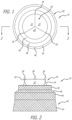
Figure 1 is a plan view of an embodiment of a device of the invention; -
Figure 2 is an elevation of an embodiment of a device of the invention; -
Figure 3 is a sectional view of the embodiment ofFigure 1 taken along section lines A-A; -
Figure 4 is a sectional view of an embodiment of the invention from a similar perspective asFigure 3 ; -
Figure 5 is a cutaway view of the device ofFigure 3 in an extended, delivery configuration; and, -
Figure 6 is a cutaway view of the device ofFigure 4 in an extended, delivery configuration. - Specific embodiments of the invention will now be described with reference to the accompanying drawings. This invention may, however, be embodied in many different forms and should not be construed as limited to the embodiments set forth herein; rather, these embodiments are provided so that this disclosure will be thorough and complete, and will fully convey the scope of the invention to those skilled in the art. The terminology used in the detailed description of the embodiments illustrated in the accompanying drawings is not intended to be limiting of the invention. In the drawings, like numbers refer to like elements.
- Referring now to the figures there is shown an embodiment of a
prosthetic valve 10 of the invention.Valve 10 generally includes avalve assembly 20 and asupport structure 40. Thevalve assembly 20 includesvalve leaflets 22 supported by awireform 24, which formscommissures 26. Thecommissures 26 may includeloops 28 for purposes of implantation and retrieval. Thevalve leaflets 22 may be formed from natural tissue, such as porcine tissue. However, synthetic materials may also be used without departing from the spirit of the invention. - The
support structure 40 may be formed from a tube of material such as a braided mesh, or may be a fenestrated structure cut from a solid tube. Good results have been obtained using a memory metal mesh braid. Thestructure 40 includes several layers that are bordered by folds or creases. Specifically, there is anouter layer 42, amiddle layer 60, and aninner layer 80.Middle layer 60 andinner layer 80 are shown inFigures 3 and4 . - The
outer layer 42 includes various sections that give it a shape suitable for nesting in a native valve annulus, such as a cardiac valve. This shape aids in its ability to prevent paravalvular leaking, as well as ensuring thevalve 10 will not migrate after implantation. In one embodiment, the outer layer includes a flaredsection 44 that leads to anupright section 46, followed by atapered section 48 and a first foldedsection 50. One skilled in the art will realize that the transitions betweensections outer layer 42 may vary without departing from the scope of the invention. - The
middle layer 60 includes a second foldedsection 62 that continues from the first foldedsection 50 of theouter layer 42. The second foldedsection 62 leads into anangled section 64, which continues to a third foldedsection 66. - The
inner layer 80, in the embodiment shown in the figures, continues from the third foldedsection 66 and does not necessarily include multiple sections. - Paravalvular leakage is prevented, in part, by strategic placement of material on the various section of the
support structure 40. In a first embodiment, shown inFigure 3 , includes three protective liners. Anouter liner 100 is sewn into the inside surface of theouter layer 42. Specifically, theouter liner 100 spans the flaredsection 44 and may extend up into theupright section 46 and taperedsection 48. All of the liners described herein are preferably circumferential. Non-limiting examples of tissue liner materials include: bio-expandable materials, impermeable fabric, compliant polymers, molded polymers, and hydrogels. It has been found that an impermeable tissue liner performs superiorly in comparison to a woven polyester liner by preventing blood flow through theouter layer 42 of thesupport structure 40. Furthermore, in all embodiments, fabric may be adhered to the tissue liners to encourage further ingrowth of native tissue. - The
outer tissue liner 100 is attached to theouter layer 42 of the mesh valve support and thesecond liner 110 is attached to themiddle layer 60 of the mesh valve support. Thetissue liner 100 may be designed to protrude through theouter layer 42 of thesupport structure 40 to form a seal against the native valve annulus. Providing a tissue liner on the inside surface of the support structure may be advantageous to placement on the outside surface of thesupport structure 40 in that the wire of the support structure is now in contact with the native tissue, providing a higher friction coefficient than a tissue-covered stent. Furthermore, during valve loading and delivery, the wire mesh provides a barrier between the relatively delicate tissue and the stent, minimizing the risk of damaging the tissue layer. - Sealing is enhanced by the tissue protruding through the gaps in the support structure in use. Varying the thickness of the liner, and/or the size of the gaps of the support structure, will provide different degrees of protrusion. The protrusion effect can be further enhanced by forming the
middle layer 60 to have elbows that act on the inside surface of theliner 100 to push it through theouter layer 42. - The
second liner 110 may be in the form of a tissue ring and may be sewn through themiddle layer 60 of themesh support 40 to make intimate contact with the tissue skirt coming off the valve leaflets, described below. Specifically, thetissue ring 110 is located on an outer surface of themiddle layer 60 on theangled section 64, and may extend onto the third foldedsection 66. Thetissue ring 110 may include bio expandable materials, impermeable fabric, compliant polymers, molded polymers, and hydrogels, just to name a few non-limiting examples. - The
tissue ring 110 enhances the sealing between the mesh layers by compressing against the tissue liners in between the layers of mesh, acting like a gasket or an o-ring. Different annulus sizes alter the height of the valve and can alter the location of the mating surfaces. As such, thetissue ring 110 is adaptable to many annulus sizes with the same mesh structure since thering 110 is smaller than thetissue liner 100 and can align itself anywhere along the length. Thetissue ring 110 may be made, in conjunction with the mesh density, to match the diamond pattern of themiddle layer 60 to enhance protrusion through the mesh gaps. Thetissue ring 110 may be attached to themiddle layer 60 using a variety of means. Non-limiting examples include: suture knots, running suture stitches, metal crimps, adhesive, cauterization, and laser adhesion. - The third liner, the
inner liner 120, is an extension, or skirt, of thevalve leaflets 22. In a first embodiment, shown inFigure 3 , the extra material of thevalve leaflets 22, forming theinner liner 120, extends into the fold between the third foldedsection 66 of themiddle layer 60 and theinner layer 80. - In a second embodiment, shown in
Figure 4 , the extra material of thevalve leaflets 22, forming theinner liner 120, is routed to an inside surface of theinner layer 80, and wraps around the third foldedsection 66 of themiddle layer 60. - Each of the embodiments of the
device 10 described herein has a delivery configuration and a deployed configuration. In the delivery configuration, the folds are straightened and the mesh support structure is in the form of an elongated tube. The liners are attached to the support structure such that, upon folding, the liners are appropriately placed. - The delivery configuration of the embodiment of
Figure 3 is shown inFigure 5. Figure 5 shows that in the delivery configuration,support structure 40 is a continuous tube that includeslayers outer layer 42, withsections Liner 100 is contained within thesupport structure 40 and generally aligned with theouter layer 42. Next ismiddle layer sections Tissue ring 110 is attached to the inner surface of thesupport structure 40 at the taperedsection 64 of themiddle layer 60. Thesupport structure 40 terminates with theinner layer 80. Thewireform 24 is attached on an outside surface of thesupport structure 40 at theinner layer 80. Thevalve tissue 22 is attached to thewireform 24 and includes the skirt that forms theinner liner 120. Thetissue 22 thus extends past the end of the wireform and along the outside surfaces of theinner layer 80 andmiddle layer 60. - The delivery configuration of the embodiment of
Figure 4 is shown inFigure 6. Figure 6 differs fromFigure 5 in that there is no tissue ring 110 (optionally) and theinner liner 120 andwireform 24 are routed on the inside of thesupport structure 40. As such,Figure 6 shows that in the delivery configuration,support structure 40 is a continuous tube that includeslayers outer layer 42, withsections Liner 100 is contained within thesupport structure 40 and generally aligned with theouter layer 42. Next ismiddle layer sections support structure 40 terminates with theinner layer 80. Thewireform 24 is attached on an inside surface of thesupport structure 40 at theinner layer 80. Thevalve tissue 22 is attached to thewireform 24 and includes the skirt that forms theinner liner 120. Thetissue 22 thus extends past the end of the wireform and along the inside surfaces of theinner layer 80 andmiddle layer 60. - Although the invention has been described in terms of particular embodiments and applications, one of ordinary skill in the art, in light of this teaching, can generate additional embodiments and modifications without departing from the spirit of or exceeding the scope of the claimed invention. Accordingly, it is to be understood that the drawings and descriptions herein are proffered by way of example to facilitate comprehension of the invention and should not be construed to limit the scope thereof.
- The application further comprises the following embodiments:
- 1. A prosthetic valve comprising:
- a support structure having a delivery configuration and a delivered configuration, wherein in the delivery configuration the support structure takes the form of an elongated tube, and in the delivered configuration, the support structure folds to take on a form that includes:
- an outer layer;
- a middle layer; and,
- an inner layer;
- a valve assembly attached to the inner layer of the support structure and including:
- a wireform including commissural points;
- valve material attached to the wireform to create valve leaflets, said valve material extending from the commissural points of the wireform to form a valve skirt attached to the middle layer of the support structure;
- an outer liner attached to an inside surface of the outer layer of the support structure.
- a support structure having a delivery configuration and a delivered configuration, wherein in the delivery configuration the support structure takes the form of an elongated tube, and in the delivered configuration, the support structure folds to take on a form that includes:
- 2. The prosthetic valve of
embodiment 1 further comprising a tissue ring attached to the middle layer of the support structure. - 3. The prosthetic valve of
embodiment 1 wherein said valve skirt is attached to an outside surface of the middle layer of the support structure. - 4. The prosthetic valve of
embodiment 1 wherein said valve skirt is attached to an inside surface of the middle layer of the support structure. - 5. The prosthetic valve of
embodiment 1 wherein said support structure comprises a mesh tube. - 6. The prosthetic valve of
embodiment 1 wherein said outer layer comprises a flared section, an upright section extending from the flared section, a tapered section extending from the upright section, and a first folded section. - 7. The prosthetic valve of embodiment 6 wherein the outer liner is attached to the flared section, the upright section and the tapered section of the outer layer.
- 8. The prosthetic valve of
embodiment 1 wherein the support structure comprises a braided wire tube with gaps being defined by the braided wire and said outer liner protrudes through the gaps. - 9. A method of preventing paravalvular leakage through a prosthetic valve comprising:
- providing a prosthetic valve with a support structure having an outer layer;
- lining an inside surface of the outer layer with a tissue liner.
- 10. The method of embodiment 9 wherein the step of lining the inside surface of the outer layer with a tissue liner comprises lining the inside surface of the outer layer with a tissue liner that protrudes through gaps formed in the support structure.
- 11. The method of embodiment 9 wherein the prosthetic valve further comprises a middle layer and an inner layer.
- 12. The method of embodiment 11 further comprising attaching a tissue ring to the middle layer.
- 13. The method of embodiment 11 wherein the step of providing the prosthetic valve with the support structure having the outer layer further comprises:
- providing the prosthetic valve with a valve assembly including a length of valve material that is attached to a wireform and extends past the wireform;
- attaching the material that extends past the wireform to at least the middle layer of the support structure.
- 14. The method of embodiment 13 further comprising attaching the material that extends past the wireform to the inner layer of the support structure.
- 15. The method of embodiment 14 wherein attaching the material that extends past the wireform to the inner layer of the support structure comprises attaching the material that extends past the wireform to an inside surface of the inner layer of the support structure.
- 16. The method of embodiment 14 wherein attaching the material that extends past the wireform to the inner layer of the support structure comprises attaching the material that extends past the wireform to an outside surface of the inner layer of the support structure.
- 17. A prosthetic valve device comprising:
- a support structure having a plurality of layers including at least an outer layer and an inner layer;
- a valve assembly connected to the inner layer;
- a tissue liner lining an inside surface of the outer layer.
- 18. The prosthetic valve device of embodiment 17 wherein said valve assembly includes a tissue skirt attached to an inside surface of said inner layer.
- 19. The prosthetic valve device of embodiment 17 wherein said valve assembly includes a tissue skirt attached to an outside surface of said inner layer.
- 20. The prosthetic valve device of embodiment 17 wherein said plurality of layers further includes a middle layer with a tissue ring attached to a surface thereof.
Claims (15)
- A prosthetic valve device comprising a support structure, whereinthe support structure (40) has a plurality of layers including at least an outer layer (42) and an inner layer (80);a valve assembly (20) connected to the inner layer;a liner (100) lining an inside surface of the outer layer, wherein the liner is configured to protrude through gaps formed in the support structure (40).
- The prosthetic valve device of claim 1, wherein the liner (100) is made from a material including one or more of a bio-expandable material, an impermeable fabric, a compliant polymer, a molded polymer and a hydrogel.
- The prosthetic valve device of any of claims 1 or 2, wherein the support structure further comprises a middle layer.
- The prosthetic valve device of any of claims 1 to 3, wherein the valve assembly comprises a tissue skirt attached to an inside surface of said inner layer.
- The prosthetic valve device of any of claims 1 to 3, wherein the valve assembly comprises a tissue skirt attached to an outside surface said inner layer.
- The prosthetic valve device of any of claims 1 to 5, wherein said support structure (40) comprises a mesh tube.
- The prosthetic valve device of any of claims 3 to 6, wherein
said support structure (40) has a delivery configuration and a delivered configuration, wherein in the delivery configuration the support structure (40) takes the form of an elongated tube, and in the delivered configuration, the support structure (40) folds to take on a form that includes:the outer layer (42);the middle layer (60); and,the inner layer (80). - The prosthetic valve device of any of claims 1 to 7, wherein the valve assembly includes:a wireform including commissural points;valve material attached to the wireform to create valve leaflets, said valve material extending from the commissural points of the wireform to form a valve skirt attached to the middle layer of the support structure (40).
- The prosthetic valve device of any of claims 3 to 8, further including a tissue ring (110) attached to a surface of the middle layer (60).
- The prosthetic valve device of claim 9, wherein the tissue ring (110) includes one or more of: a bio-expandable material, an impermeable fabric, a compliant polymehr, a molded polymer and a hydrogel.
- The prosthetic valve device of any of claims 1 to 10, wherein said outer layer (42) comprises a flared section, an upright section extending from the flared section, a tapered section extending from the upright section, and a first folded section.
- The prosthetic valve device of claim 11, wherein the liner (100) is attached to the flared section, the upright section and the tapered section of the outer layer (42).
- The prosthetic valve device of any of claims 8 to 12, wherein the material that extends past the wireform is attached to an inside surface of the inner layer (80) of the support structure (40).
- The prosthetic valve device of any of claims 8 to 12, wherein the material that extends past the wireform is attached to an outside surface of the inner layer (80) of the support structure (40).
- The prosthetic valve device of claim 1, wherein the support structure comprises a braided wire tube with the gaps being defined by the braided wire.
Applications Claiming Priority (3)
| Application Number | Priority Date | Filing Date | Title |
|---|---|---|---|
| US201762506480P | 2017-05-15 | 2017-05-15 | |
| PCT/US2018/032403 WO2018213137A1 (en) | 2017-05-15 | 2018-05-11 | Valve sealing tissue and mesh structure |
| EP18802714.8A EP3634306B1 (en) | 2017-05-15 | 2018-05-11 | Valve sealing tissue and mesh structure |
Related Parent Applications (1)
| Application Number | Title | Priority Date | Filing Date |
|---|---|---|---|
| EP18802714.8A Division EP3634306B1 (en) | 2017-05-15 | 2018-05-11 | Valve sealing tissue and mesh structure |
Publications (2)
| Publication Number | Publication Date |
|---|---|
| EP4578427A2 true EP4578427A2 (en) | 2025-07-02 |
| EP4578427A3 EP4578427A3 (en) | 2025-08-20 |
Family
ID=64096347
Family Applications (2)
| Application Number | Title | Priority Date | Filing Date |
|---|---|---|---|
| EP18802714.8A Active EP3634306B1 (en) | 2017-05-15 | 2018-05-11 | Valve sealing tissue and mesh structure |
| EP25177609.2A Pending EP4578427A3 (en) | 2017-05-15 | 2018-05-11 | Valve sealing tissue and mesh structure |
Family Applications Before (1)
| Application Number | Title | Priority Date | Filing Date |
|---|---|---|---|
| EP18802714.8A Active EP3634306B1 (en) | 2017-05-15 | 2018-05-11 | Valve sealing tissue and mesh structure |
Country Status (5)
| Country | Link |
|---|---|
| US (1) | US11839539B2 (en) |
| EP (2) | EP3634306B1 (en) |
| JP (1) | JP2020519394A (en) |
| CA (1) | CA3063604A1 (en) |
| WO (1) | WO2018213137A1 (en) |
Families Citing this family (22)
| Publication number | Priority date | Publication date | Assignee | Title |
|---|---|---|---|---|
| AU2016380259B2 (en) * | 2015-12-28 | 2020-10-22 | Tendyne Holdings, Inc. | Atrial pocket closures for prosthetic heart valves |
| US10383725B2 (en) | 2016-08-11 | 2019-08-20 | 4C Medical Technologies, Inc. | Heart chamber prosthetic valve implant with base, mesh and dome sections with single chamber anchoring for preservation, supplementation and/or replacement of native valve function |
| US10653523B2 (en) | 2017-01-19 | 2020-05-19 | 4C Medical Technologies, Inc. | Systems, methods and devices for delivery systems, methods and devices for implanting prosthetic heart valves |
| US12029647B2 (en) | 2017-03-07 | 2024-07-09 | 4C Medical Technologies, Inc. | Systems, methods and devices for prosthetic heart valve with single valve leaflet |
| US12036113B2 (en) | 2017-06-14 | 2024-07-16 | 4C Medical Technologies, Inc. | Delivery of heart chamber prosthetic valve implant |
| US10874513B2 (en) * | 2018-02-12 | 2020-12-29 | 4C Medical Technologies, Inc. | Expandable frames and paravalvular leak mitigation systems for implantable prosthetic heart valve devices |
| US11857441B2 (en) | 2018-09-04 | 2024-01-02 | 4C Medical Technologies, Inc. | Stent loading device |
| CN113164258B (en) * | 2018-11-01 | 2024-08-27 | 爱德华兹生命科学公司 | Transcatheter pulmonary valve regeneration |
| US12544226B2 (en) | 2019-02-14 | 2026-02-10 | 4C Medical Technologies, Inc. | Hydrophilic skirt for paravalvular leak mitigation and fit and apposition optimization for prosthetic heart valve implants |
| US11452628B2 (en) | 2019-04-15 | 2022-09-27 | 4C Medical Technologies, Inc. | Loading systems for collapsible prosthetic heart valve devices and methods thereof |
| US12133797B2 (en) | 2020-01-31 | 2024-11-05 | 4C Medical Technologies, Inc. | Prosthetic heart valve delivery system: paddle attachment feature |
| US11931253B2 (en) * | 2020-01-31 | 2024-03-19 | 4C Medical Technologies, Inc. | Prosthetic heart valve delivery system: ball-slide attachment |
| US12053375B2 (en) | 2020-03-05 | 2024-08-06 | 4C Medical Technologies, Inc. | Prosthetic mitral valve with improved atrial and/or annular apposition and paravalvular leakage mitigation |
| US11992403B2 (en) | 2020-03-06 | 2024-05-28 | 4C Medical Technologies, Inc. | Devices, systems and methods for improving recapture of prosthetic heart valve device with stent frame having valve support with inwardly stent cells |
| EP3881801B1 (en) * | 2020-03-18 | 2025-04-23 | Medtronic Inc. | Improvements in or relating to the delivery and unsheathing of prosthetic heart valves |
| US20210330455A1 (en) * | 2020-04-24 | 2021-10-28 | ReValve Solutions Inc. | Devices, systems, and methods for a collapsible replacement heart valve |
| US12616572B2 (en) | 2020-05-15 | 2026-05-05 | ReValve Solutions, Inc. | Devices, systems, and methods for a valve replacement |
| CN111388147A (en) * | 2020-04-26 | 2020-07-10 | 上海捍宇医疗科技有限公司 | Artificial heart valve |
| EP4216875A4 (en) | 2020-09-23 | 2024-11-13 | Revalve Solutions Inc. | Devices, systems, and methods for an implantable heart-valve adapter |
| CA3240859A1 (en) * | 2021-12-17 | 2025-02-27 | Edwards Lifesciences Corporation | Motorized implant delivery device, implant, loading system, and method of using |
| US12588998B1 (en) | 2022-09-01 | 2026-03-31 | 4C Medical Technologies, Inc. | Prosthetic heart valve for natural blood flow |
| US20240366366A1 (en) | 2023-03-24 | 2024-11-07 | 4C Medical Technologies, Inc. | Implant delivery |
Family Cites Families (9)
| Publication number | Priority date | Publication date | Assignee | Title |
|---|---|---|---|---|
| US4473423A (en) * | 1982-05-03 | 1984-09-25 | University Of Utah | Artificial heart valve made by vacuum forming technique |
| US6610088B1 (en) * | 2000-05-03 | 2003-08-26 | Shlomo Gabbay | Biologically covered heart valve prosthesis |
| US6755857B2 (en) * | 2001-12-12 | 2004-06-29 | Sulzer Carbomedics Inc. | Polymer heart valve with perforated stent and sewing cuff |
| WO2005084595A1 (en) | 2004-02-27 | 2005-09-15 | Cardiacmd, Inc. | Prosthetic heart valve delivery systems and methods |
| US8974523B2 (en) * | 2005-05-27 | 2015-03-10 | Hlt, Inc. | Stentless support structure |
| CA2961053C (en) * | 2009-04-15 | 2019-04-30 | Edwards Lifesciences Cardiaq Llc | Vascular implant and delivery system |
| CN103124537B (en) | 2010-05-10 | 2015-08-26 | 心叶科技公司 | Without rack supporting structure |
| EP3403616B1 (en) | 2011-08-11 | 2022-05-11 | Tendyne Holdings, Inc. | Improvements for prosthetic valves and related inventions |
| US9039757B2 (en) | 2011-10-19 | 2015-05-26 | Twelve, Inc. | Prosthetic heart valve devices, prosthetic mitral valves and associated systems and methods |
-
2018
- 2018-05-11 US US15/977,842 patent/US11839539B2/en active Active
- 2018-05-11 CA CA3063604A patent/CA3063604A1/en not_active Abandoned
- 2018-05-11 EP EP18802714.8A patent/EP3634306B1/en active Active
- 2018-05-11 JP JP2019563162A patent/JP2020519394A/en active Pending
- 2018-05-11 EP EP25177609.2A patent/EP4578427A3/en active Pending
- 2018-05-11 WO PCT/US2018/032403 patent/WO2018213137A1/en not_active Ceased
Also Published As
| Publication number | Publication date |
|---|---|
| EP4578427A3 (en) | 2025-08-20 |
| US11839539B2 (en) | 2023-12-12 |
| JP2020519394A (en) | 2020-07-02 |
| CA3063604A1 (en) | 2018-11-22 |
| EP3634306A4 (en) | 2020-05-06 |
| US20180325664A1 (en) | 2018-11-15 |
| EP3634306B1 (en) | 2025-05-21 |
| EP3634306A1 (en) | 2020-04-15 |
| WO2018213137A1 (en) | 2018-11-22 |
Similar Documents
| Publication | Publication Date | Title |
|---|---|---|
| US11839539B2 (en) | Valve sealing tissue and mesh structure | |
| US20250009504A1 (en) | Stationary Intra-Annular Halo Designs For Paravalvular Leak (PVL) Reduction-Passive Channel Filling Cuff Designs | |
| US12156807B2 (en) | Stent seals and method of production | |
| US10299926B2 (en) | Transcatheter valve with paravalvular leak sealing ring | |
| US11298889B2 (en) | Laminated sealing member for prosthetic heart valve | |
| US20170216024A1 (en) | Sealing elements for intracardiac devices | |
| KR102658262B1 (en) | Heart valve frame design with uneven struts | |
| US11076951B2 (en) | Systems for replacing a native heart valve and aorta with a prosthetic heart valve and conduit | |
| KR100850035B1 (en) | Stent valve | |
| EP3043745B1 (en) | Stent designs for prosthetic heart valves | |
| US20200008939A1 (en) | Stent Assembly For Use in Prosthetic Heart Valves | |
| US9937040B2 (en) | Method of repairing an aortic valve | |
| US20150209136A1 (en) | Stationary intra-annular halo designs for paravalvular leak (pvl) reduction - active channel filling cuff designs | |
| US20170273782A1 (en) | Cardiac valve support devices having improved compatibility with transcatheter prosthetic valves | |
| US20130310927A1 (en) | Implantable Valve System | |
| CN115068169A (en) | Systems, devices, and methods for implantable valve skirts | |
| US12383396B2 (en) | Expandable sleeved stent and method of making such stent |
Legal Events
| Date | Code | Title | Description |
|---|---|---|---|
| PUAI | Public reference made under article 153(3) epc to a published international application that has entered the european phase |
Free format text: ORIGINAL CODE: 0009012 |
|
| STAA | Information on the status of an ep patent application or granted ep patent |
Free format text: STATUS: THE APPLICATION HAS BEEN PUBLISHED |
|
| AC | Divisional application: reference to earlier application |
Ref document number: 3634306 Country of ref document: EP Kind code of ref document: P |
|
| AK | Designated contracting states |
Kind code of ref document: A2 Designated state(s): AL AT BE BG CH CY CZ DE DK EE ES FI FR GB GR HR HU IE IS IT LI LT LU LV MC MK MT NL NO PL PT RO RS SE SI SK SM TR |
|
| REG | Reference to a national code |
Ref country code: DE Ref legal event code: R079 Free format text: PREVIOUS MAIN CLASS: A61F0002240000 Ipc: A61F0002040000 |
|
| PUAL | Search report despatched |
Free format text: ORIGINAL CODE: 0009013 |
|
| AK | Designated contracting states |
Kind code of ref document: A3 Designated state(s): AL AT BE BG CH CY CZ DE DK EE ES FI FR GB GR HR HU IE IS IT LI LT LU LV MC MK MT NL NO PL PT RO RS SE SI SK SM TR |
|
| RIC1 | Information provided on ipc code assigned before grant |
Ipc: A61F 2/04 20130101AFI20250717BHEP Ipc: A61F 2/24 20060101ALI20250717BHEP |
|
| P01 | Opt-out of the competence of the unified patent court (upc) registered |
Free format text: CASE NUMBER: UPC_APP_2963_4578427/2025 Effective date: 20250811 |
|
| STAA | Information on the status of an ep patent application or granted ep patent |
Free format text: STATUS: REQUEST FOR EXAMINATION WAS MADE |
|
| 17P | Request for examination filed |
Effective date: 20260220 |
|
| GRAP | Despatch of communication of intention to grant a patent |
Free format text: ORIGINAL CODE: EPIDOSNIGR1 |
|
| STAA | Information on the status of an ep patent application or granted ep patent |
Free format text: STATUS: GRANT OF PATENT IS INTENDED |
|
| INTG | Intention to grant announced |
Effective date: 20260507 |