EP4578402A1 - Ultrasound diagnostic apparatus and method of controlling ultrasound diagnostic apparatus - Google Patents
Ultrasound diagnostic apparatus and method of controlling ultrasound diagnostic apparatus Download PDFInfo
- Publication number
- EP4578402A1 EP4578402A1 EP24217055.3A EP24217055A EP4578402A1 EP 4578402 A1 EP4578402 A1 EP 4578402A1 EP 24217055 A EP24217055 A EP 24217055A EP 4578402 A1 EP4578402 A1 EP 4578402A1
- Authority
- EP
- European Patent Office
- Prior art keywords
- organ
- ultrasound
- template
- posture
- subject
- Prior art date
- Legal status (The legal status is an assumption and is not a legal conclusion. Google has not performed a legal analysis and makes no representation as to the accuracy of the status listed.)
- Granted
Links
Images


Classifications
-
- A—HUMAN NECESSITIES
- A61—MEDICAL OR VETERINARY SCIENCE; HYGIENE
- A61B—DIAGNOSIS; SURGERY; IDENTIFICATION
- A61B8/00—Diagnosis using ultrasonic, sonic or infrasonic waves
- A61B8/48—Diagnostic techniques
- A61B8/483—Diagnostic techniques involving the acquisition of a 3D volume of data
-
- A—HUMAN NECESSITIES
- A61—MEDICAL OR VETERINARY SCIENCE; HYGIENE
- A61B—DIAGNOSIS; SURGERY; IDENTIFICATION
- A61B5/00—Measuring for diagnostic purposes; Identification of persons
- A61B5/103—Measuring devices for testing the shape, pattern, colour, size or movement of the body or parts thereof, for diagnostic purposes
- A61B5/11—Measuring movement of the entire body or parts thereof, e.g. head or hand tremor or mobility of a limb
-
- A—HUMAN NECESSITIES
- A61—MEDICAL OR VETERINARY SCIENCE; HYGIENE
- A61B—DIAGNOSIS; SURGERY; IDENTIFICATION
- A61B5/00—Measuring for diagnostic purposes; Identification of persons
- A61B5/103—Measuring devices for testing the shape, pattern, colour, size or movement of the body or parts thereof, for diagnostic purposes
- A61B5/11—Measuring movement of the entire body or parts thereof, e.g. head or hand tremor or mobility of a limb
- A61B5/1113—Local tracking of patients, e.g. in a hospital or private home
-
- A—HUMAN NECESSITIES
- A61—MEDICAL OR VETERINARY SCIENCE; HYGIENE
- A61B—DIAGNOSIS; SURGERY; IDENTIFICATION
- A61B5/00—Measuring for diagnostic purposes; Identification of persons
- A61B5/103—Measuring devices for testing the shape, pattern, colour, size or movement of the body or parts thereof, for diagnostic purposes
- A61B5/11—Measuring movement of the entire body or parts thereof, e.g. head or hand tremor or mobility of a limb
- A61B5/1113—Local tracking of patients, e.g. in a hospital or private home
- A61B5/1114—Tracking parts of the body
-
- A—HUMAN NECESSITIES
- A61—MEDICAL OR VETERINARY SCIENCE; HYGIENE
- A61B—DIAGNOSIS; SURGERY; IDENTIFICATION
- A61B5/00—Measuring for diagnostic purposes; Identification of persons
- A61B5/103—Measuring devices for testing the shape, pattern, colour, size or movement of the body or parts thereof, for diagnostic purposes
- A61B5/11—Measuring movement of the entire body or parts thereof, e.g. head or hand tremor or mobility of a limb
- A61B5/1116—Determining posture transitions
-
- A—HUMAN NECESSITIES
- A61—MEDICAL OR VETERINARY SCIENCE; HYGIENE
- A61B—DIAGNOSIS; SURGERY; IDENTIFICATION
- A61B5/00—Measuring for diagnostic purposes; Identification of persons
- A61B5/103—Measuring devices for testing the shape, pattern, colour, size or movement of the body or parts thereof, for diagnostic purposes
- A61B5/11—Measuring movement of the entire body or parts thereof, e.g. head or hand tremor or mobility of a limb
- A61B5/1126—Measuring movement of the entire body or parts thereof, e.g. head or hand tremor or mobility of a limb using a particular sensing technique
- A61B5/1128—Measuring movement of the entire body or parts thereof, e.g. head or hand tremor or mobility of a limb using a particular sensing technique using image analysis
-
- A—HUMAN NECESSITIES
- A61—MEDICAL OR VETERINARY SCIENCE; HYGIENE
- A61B—DIAGNOSIS; SURGERY; IDENTIFICATION
- A61B8/00—Diagnosis using ultrasonic, sonic or infrasonic waves
- A61B8/08—Clinical applications
- A61B8/0833—Clinical applications involving detecting or locating foreign bodies or organic structures
- A61B8/085—Clinical applications involving detecting or locating foreign bodies or organic structures for locating body or organic structures, e.g. tumours, calculi, blood vessels, nodules
-
- A—HUMAN NECESSITIES
- A61—MEDICAL OR VETERINARY SCIENCE; HYGIENE
- A61B—DIAGNOSIS; SURGERY; IDENTIFICATION
- A61B8/00—Diagnosis using ultrasonic, sonic or infrasonic waves
- A61B8/42—Details of probe positioning or probe attachment to the patient
- A61B8/4272—Details of probe positioning or probe attachment to the patient involving the acoustic interface between the transducer and the tissue
- A61B8/429—Details of probe positioning or probe attachment to the patient involving the acoustic interface between the transducer and the tissue characterised by determining or monitoring the contact between the transducer and the tissue
-
- A—HUMAN NECESSITIES
- A61—MEDICAL OR VETERINARY SCIENCE; HYGIENE
- A61B—DIAGNOSIS; SURGERY; IDENTIFICATION
- A61B8/00—Diagnosis using ultrasonic, sonic or infrasonic waves
- A61B8/46—Ultrasonic, sonic or infrasonic diagnostic devices with special arrangements for interfacing with the operator or the patient
- A61B8/461—Displaying means of special interest
-
- A—HUMAN NECESSITIES
- A61—MEDICAL OR VETERINARY SCIENCE; HYGIENE
- A61B—DIAGNOSIS; SURGERY; IDENTIFICATION
- A61B8/00—Diagnosis using ultrasonic, sonic or infrasonic waves
- A61B8/46—Ultrasonic, sonic or infrasonic diagnostic devices with special arrangements for interfacing with the operator or the patient
- A61B8/461—Displaying means of special interest
- A61B8/466—Displaying means of special interest adapted to display 3D data
-
- A—HUMAN NECESSITIES
- A61—MEDICAL OR VETERINARY SCIENCE; HYGIENE
- A61B—DIAGNOSIS; SURGERY; IDENTIFICATION
- A61B8/00—Diagnosis using ultrasonic, sonic or infrasonic waves
- A61B8/52—Devices using data or image processing specially adapted for diagnosis using ultrasonic, sonic or infrasonic waves
- A61B8/5207—Devices using data or image processing specially adapted for diagnosis using ultrasonic, sonic or infrasonic waves involving processing of raw data to produce diagnostic data, e.g. for generating an image
-
- A—HUMAN NECESSITIES
- A61—MEDICAL OR VETERINARY SCIENCE; HYGIENE
- A61B—DIAGNOSIS; SURGERY; IDENTIFICATION
- A61B8/00—Diagnosis using ultrasonic, sonic or infrasonic waves
- A61B8/42—Details of probe positioning or probe attachment to the patient
- A61B8/4245—Details of probe positioning or probe attachment to the patient involving determining the position of the probe, e.g. with respect to an external reference frame or to the patient
- A61B8/4263—Details of probe positioning or probe attachment to the patient involving determining the position of the probe, e.g. with respect to an external reference frame or to the patient using sensors not mounted on the probe, e.g. mounted on an external reference frame
-
- A—HUMAN NECESSITIES
- A61—MEDICAL OR VETERINARY SCIENCE; HYGIENE
- A61B—DIAGNOSIS; SURGERY; IDENTIFICATION
- A61B8/00—Diagnosis using ultrasonic, sonic or infrasonic waves
- A61B8/52—Devices using data or image processing specially adapted for diagnosis using ultrasonic, sonic or infrasonic waves
- A61B8/5215—Devices using data or image processing specially adapted for diagnosis using ultrasonic, sonic or infrasonic waves involving processing of medical diagnostic data
- A61B8/5238—Devices using data or image processing specially adapted for diagnosis using ultrasonic, sonic or infrasonic waves involving processing of medical diagnostic data for combining image data of patient, e.g. merging several images from different acquisition modes into one image
Definitions
- the present invention relates to an ultrasound diagnostic apparatus used in a case of comprehensively observing an organ of a subject and a method of controlling the ultrasound diagnostic apparatus.
- an ultrasound image representing a tomogram of a subject is captured by using a so-called ultrasound diagnostic apparatus, thereby observing an inside of the subject.
- a user such as a doctor, comprehensively observes a specific organ of the subject.
- the user usually sequentially captures ultrasound images while determining a captured part of the subject by checking the captured ultrasound image, but a user having a low skill level in an observation using the ultrasound diagnostic apparatus may have difficulty in determining which part of the subject is imaged even by checking the ultrasound image. Therefore, for example, as disclosed in JP2021-053379A , a technology has been developed in which a region that has been scanned or a region that has not yet been scanned in an organ as an observation target is specified and displayed by comparing data obtained by transmitting and receiving ultrasound to and from the organ as the observation target with data representing a reference shape of the organ as the observation target.
- the transceiver circuit 12, the image generation unit 21, and the three-dimensional ultrasound image generation unit 25 constitute a three-dimensional ultrasound image acquisition unit 31.
- the image generation unit 21, the display controller 22, the three-dimensional ultrasound image generation unit 25, the template selection unit 27, the scanning progress status output unit 28, and the body controller 29 constitute a processor 32 for the apparatus body 2.
- the image generation unit 21 has a configuration in which a signal processing unit 45, a digital scan converter (DSC) 46, and an image processing unit 47 are sequentially connected in series to each other.
- DSC digital scan converter
- the image processing unit 47 performs various types of necessary image processing such as gradation processing on the B-mode image signal input from the DSC 46, and then transmits the B-mode image signal to the display controller 22 and the image memory 24.
- the B-mode image signal that is image-processed by the image processing unit 47 will be referred to as an ultrasound image.
- the probe tracking sensor 13 is a sensor device that acquires position/posture information of the ultrasound probe 1 under the control of the body controller 29.
- the user in general, in a case in which the user performs an examination on the subject using the ultrasound diagnostic apparatus, the user often performs the examination while changing the posture of the ultrasound probe 1, that is, an inclination angle and a rotation angle of the ultrasound probe 1 in a state in which the ultrasound probe 1 is in contact with a body surface of the subject and moving the position of the ultrasound probe 1.
- the position/posture information of the ultrasound probe 1 acquired by the probe tracking sensor 13 includes information on the posture and the position of the ultrasound probe 1.
- the probe tracking sensor 13 can include, for example, at least one of a so-called inertial sensor, a magnetic sensor, an optical sensor, or an optical camera.
- the inertial sensor can include, for example, at least one of a so-called acceleration sensor or a gyro sensor.
- the ultrasound image generated by the image generation unit 21 and the position/posture information of the ultrasound probe 1 acquired by the probe tracking sensor 13 in a case in which the ultrasound image is generated are stored in the image memory 24 in association with each other.
- the template memory 26 is a memory in which a plurality of organ templates for a specific organ of the subject are stored.
- the plurality of organ templates represent a plurality of three-dimensional shapes of the organ deformed in accordance with a posture of the subject, such as a so-called sitting posture, decubitus posture, ventral decubitus posture, or lateral decubitus posture. That is, the template memory 26 stores, for the specific organ, the plurality of organ templates corresponding to the posture of the subject, such as an organ template corresponding to the sitting posture, an organ template corresponding to the decubitus posture, an organ template corresponding to the ventral decubitus posture, and an organ template corresponding to the lateral decubitus posture.
- both the organ templates of a left lateral decubitus posture in which the subject lies on a left side and a right lateral decubitus posture in which the subject lies on a right side can be used.
- a recording medium such as a flash memory, an HDD, an SSD, an FD, an MO disk, an MT, a RAM, a CD, a DVD, an SD card, or a USB memory can be used.
- the template selection unit 27 selects one organ template from among the plurality of organ templates stored in the template memory 26 in accordance with the posture of the subject.
- the posture of the subject can be input by, for example, the user of the ultrasound diagnostic apparatus, such as a doctor, via the input device 30.
- the template selection unit 27 can select the organ template of the liver corresponding to the sitting posture.
- the scanning progress status output unit 28 specifies a scanning progress status of the ultrasound probe 1 for the organ as the observation target by performing registration between the three-dimensional ultrasound image acquired by the three-dimensional ultrasound image acquisition unit 31 and one organ template selected by the template selection unit 27, and outputs the specified scanning progress status.
- the scanning progress status output unit 28 can perform the registration between the three-dimensional ultrasound image and one organ template by, for example, an algorithm such as a so-called random sample consensus (RANSAC) or an iterative closest point (ICP), a so-called machine learning method, or a combination thereof. It should be noted that the processing of the registration can include, for example, processing of deforming the three-dimensional ultrasound image or one organ template.
- RANSAC random sample consensus
- ICP iterative closest point
- machine learning method a so-called machine learning method
- the scanning progress status of the ultrasound probe 1 indicates a progress degree of the scanning using the ultrasound probe 1 for the organ as the observation target.
- the scanning progress status output unit 28 can specify a region that has been scanned using the ultrasound probe 1 in the organ as the observation target as the scanning progress status, to display the region that has been scanned, on the monitor 23.
- the scanning progress status output unit 28 can display a region R1 that has been scanned, on the monitor 23 in a state of being superimposed on the organ template of the liver selected by the template selection unit 27 as shown in Fig. 6 .
- This example shows that the scanning of a part of a right lobe A1 of the liver is completed out of the right lobe A1 and a left lobe A2.
- the scanning progress status output unit 28 can specify a region of the organ as the observation target that has not yet been scanned using the ultrasound probe 1 as the scanning progress status, to display the region that has not yet been scanned, on the monitor 23.
- the scanning progress status output unit 28 can display a region R2 that has not yet been scanned, on the monitor 23 in a state of being superimposed on the organ template of the liver selected by the template selection unit 27 as shown in Fig. 7 . This example shows that the scanning of a part of the right lobe A1 and the entire left lobe A2 of the liver is not completed out of the right lobe A1 and the left lobe A2.
- the display controller 22 performs predetermined processing on the ultrasound image transmitted from the image generation unit 21, the scanning progress status of the ultrasound probe 1 output by the scanning progress status output unit 28, and the like, and displays the ultrasound image, the scanning progress status, and the like on the monitor 23, under the control of the body controller 29.
- the body controller 29 controls the respective units of the apparatus body 2, the transceiver circuit 12 of the ultrasound probe 1, and the probe tracking sensor 13 based on a control program and the like stored in advance.
- the input device 30 is an input device for the user to perform an input operation, and is configured by, for example, a device such as a keyboard, a mouse, a trackball, a touchpad, and a touch sensor disposed in a state of being superimposed on the monitor 23.
- the processor 32 including the image generation unit 21, the display controller 22, the three-dimensional ultrasound image generation unit 25, the template selection unit 27, the scanning progress status output unit 28, and the body controller 29 is configured by a central processing unit (CPU) and the control program for causing the CPU to execute various types of processing, but the processor 32 may be configured by a field programmable gate array (FPGA), a digital signal processor (DSP), an application specific integrated circuit (ASIC), a graphics processing unit (GPU), or other integrated circuits (IC), or may be configured by a combination thereof.
- FPGA field programmable gate array
- DSP digital signal processor
- ASIC application specific integrated circuit
- GPU graphics processing unit
- IC integrated circuits
- the image generation unit 21, the display controller 22, the three-dimensional ultrasound image generation unit 25, the template selection unit 27, the scanning progress status output unit 28, and the body controller 29 can also be configured by being integrated partially or entirely into one CPU or the like.
- step ST1 the posture of the subject is input by the user via the input device 30.
- the body controller 29 receives the posture of the subject input by the user.
- step ST2 the template selection unit 27 selects one organ template corresponding to the posture of the subject which is input by the user in step ST1 and received by the body controller 29, from among the plurality of organ templates of the liver stored in the template memory 26.
- step ST3 the image generation unit 21 generates the ultrasound image of the liver of the subject.
- the transmission and reception of the ultrasound from the plurality of transducers of the transducer array 11 are started in accordance with the drive signal from the pulser 41 of the transceiver circuit 12 of the ultrasound probe 1, the ultrasound echo from the subject is received by the plurality of transducers of the transducer array 11, and the reception signal as the analog signal is output to the amplifying unit 42, is amplified, and then is subjected to the AD conversion via the AD conversion unit 43 to acquire the reception data.
- step ST5 the three-dimensional ultrasound image generation unit 25 generates the three-dimensional ultrasound image of the liver of the subject based on a plurality of pieces of the position/posture information of the ultrasound probe 1 and the ultrasound images of the plurality of frames obtained by repeating step ST3 and step ST4.
- the three-dimensional ultrasound image generation unit 25 can generate the three-dimensional ultrasound image of the liver by arranging the ultrasound images of the plurality of frames in accordance with the position/posture information of the ultrasound probe 1 associated with each ultrasound image.
- the scanning progress status output unit 28 can display the scanning progress status specified in this way for each of the plurality of sections on the monitor 23 as, for example, a numerical value.
- the scanning progress status output unit 28 can also display the scanning progress status specified for each of the plurality of sections on the monitor 23, for example, by displaying a so-called progress bar on the monitor 23.
- the scanning progress status output unit 28 can also output the scanning progress status specified for each of the plurality of sections as a voice, for example, via the speaker.
- the scanning progress status of the ultrasound probe 1 can be more accurately output, and thus the user can more reliably perform the comprehensive observation of the organ as the observation target.
- the body controller 29 determines whether or not a structure of the generated three-dimensional ultrasound image of the landmark is defective, for example, whether or not the shape of the three-dimensional ultrasound image of the portal vein, which is the landmark, is smoothly continuous, and can end the pre-scanning and start the main scanning in a case in which it is determined that the structure of the three-dimensional ultrasound image of the landmark is not defective.
- the three-dimensional ultrasound image generation unit 25 generates the three-dimensional ultrasound image based on the position/posture information of the ultrasound probe 1 acquired by the probe tracking sensor 13 and the ultrasound images of the plurality of frames generated by the image generation unit 21, the method of generating the three-dimensional ultrasound image is not particularly limited to this.
- the three-dimensional ultrasound image generation unit 25 can generate the three-dimensional ultrasound image by arranging the ultrasound images of the plurality of frames generated by the image generation unit 21 in time series without using the position/posture information of the ultrasound probe 1 acquired by the probe tracking sensor 13.
- Embodiment 1 the description has been made in which the user inputs the posture of the subject via the input device 30, but the ultrasound diagnostic apparatus can also automatically detect the posture of the subject.
- Fig. 11 shows a configuration of an ultrasound diagnostic apparatus according to Embodiment 2.
- the ultrasound diagnostic apparatus according to Embodiment 2 comprises an apparatus body 2A instead of the apparatus body 2 and further comprises an optical camera 51, with respect to the ultrasound diagnostic apparatus according to Embodiment 1 shown in Fig. 1 .
- the optical camera 51 is provided outside the ultrasound probe 1 and the apparatus body 2A, for example, the optical camera 51 may be attached to or incorporated in the apparatus body 2A.
- the apparatus body 2A comprises a body controller 29A instead of the body controller 29 and further comprises an optical image analysis unit 52, in the apparatus body 2 according to Embodiment 1.
- the optical image analysis unit 52 is connected to the optical camera 51.
- the optical image analysis unit 52 is connected to the template selection unit 27 and the body controller 29A.
- the optical camera 51 and the optical image analysis unit 52 constitute a posture detection unit 53.
- the image generation unit 21, the display controller 22, the three-dimensional ultrasound image generation unit 25, the template selection unit 27, the scanning progress status output unit 28, the body controller 29A, and the optical image analysis unit 52 constitute a processor 32A for the apparatus body 2A.
- the optical camera 51 includes, for example, an image sensor such as a so-called chargecoupled device (CCD) image sensor or a so-called a complementary metal-oxide-semiconductor (CMOS) image sensor, and images the subject to acquire an optical image.
- the optical camera 51 transmits the acquired optical image to the optical image analysis unit 52.
- the optical image analysis unit 52 analyzes the optical image acquired by the optical camera 51, to detect the posture of the subject.
- the optical image analysis unit 52 can detect the posture of the subject from the optical image, for example, by a method of using a trained model in machine learning, which has learned a relationship between the optical image in which the subject is shown and the posture of the subject.
- the template selection unit 27 can calculate a degree of similarity with respect to the posture of the subject detected by the posture detection unit 53 for each of the plurality of organ templates stored in the template memory 26, for example, and select one organ template having the highest degree of similarity.
- the template selection unit 27 can calculate the degree of similarity by using, for example, an algorithm such as a so-called support-vector machine (SVM), a decision tree, deep learning, or collaborative filtering, or a combination of these algorithms.
- SVM support-vector machine
- the template selection unit 27 can also select one organ template by using, for example, a trained model in machine learning, which has learned a relationship between a detection result, which is the output from the posture detection unit 53 in accordance with the posture of the subject, and the organ template.
- the scanning progress status output unit 28 specifies the scanning progress status of the ultrasound probe 1 by performing registration between the three-dimensional ultrasound image generated by the three-dimensional ultrasound image generation unit 25 and one organ template selected by the template selection unit 27, and outputs the specified scanning progress status.
- the posture detection unit 53 configured by the optical camera 51 and the optical image analysis unit 52 automatically detects the posture of the subject from the optical image of the subject, so that the user does not need to input the posture of the subject via the input device 30, and can more easily perform the comprehensive observation of the organ of the subject.
- Fig. 12 shows a configuration of an ultrasound diagnostic apparatus according to Embodiment 3.
- the ultrasound diagnostic apparatus according to Embodiment 3 comprises an apparatus body 2B instead of the apparatus body 2A and comprises a plurality of pressure sensors 54 disposed on an examination table B instead of the optical camera 51 in the ultrasound diagnostic apparatus of Embodiment 2 shown in Fig. 11 .
- the apparatus body 2B comprises a body controller 29B instead of the body controller 29A and comprises a signal analysis unit 55 instead of the optical image analysis unit 52 in the apparatus body 2A according to Embodiment 2.
- the signal analysis unit 55 is connected to the plurality of pressure sensors 54 disposed on the examination table B.
- the signal analysis unit 55 is connected to the template selection unit 27 and the body controller 29B.
- the plurality of pressure sensors 54 and the signal analysis unit 55 constitute a posture detection unit 56.
- the image generation unit 21, the display controller 22, the three-dimensional ultrasound image generation unit 25, the template selection unit 27, the scanning progress status output unit 28, the body controller 29B, and the signal analysis unit 55 constitute a processor 32B for the apparatus body 2B.
- the plurality of pressure sensors 54 are disposed on the examination table B on which the subject is placed in a case in which the subject undergoes the examination, and detect a detection signal representing a distribution of pressure from the subject, which correspond to the posture of the subject. Since a shape and an area of a region in which the subject touches the bed vary depending on the posture of the subject on the bed, the detection signal representing the distribution of pressure corresponding to each posture of the subject is detected by the plurality of pressure sensors 54.
- the signal analysis unit 55 analyzes the detection signals acquired by the plurality of pressure sensors 54, to detect the posture of the subject.
- the signal analysis unit 55 can store, for example, templates of a plurality of detection signals corresponding to a plurality of postures of the subject in advance, to detect the posture of the subject by comparing the detection signals acquired by the plurality of pressure sensors 54 with the templates.
- the signal analysis unit 55 can also detect the posture of the subject by using a trained model in machine learning, which has learned a relationship between the posture of the subject and the detection signal.
- the template selection unit 27 selects one organ template corresponding to the posture of the subject detected by the signal analysis unit 55 from among the plurality of organ templates stored in the template memory 26 for the organ as the observation target.
- the template selection unit 27 can calculate a degree of similarity with respect to the posture of the subject detected by the posture detection unit 56 for each of the plurality of organ templates stored in the template memory 26, for example, and select one organ template having the highest degree of similarity.
- the template selection unit 27 can calculate the degree of similarity by using, for example, an algorithm such as a so-called SVM, a decision tree, deep learning, or collaborative filtering, or a combination of these algorithms.
- the template selection unit 27 can also select one organ template by using, for example, a trained model in machine learning, which has learned a relationship between a detection result, which is the output from the posture detection unit 56 in accordance with the posture of the subject, and the organ template.
- the scanning progress status output unit 28 specifies the scanning progress status of the ultrasound probe 1 by performing registration between the three-dimensional ultrasound image generated by the three-dimensional ultrasound image generation unit 25 and one organ template selected by the template selection unit 27, and outputs the specified scanning progress status.
- the posture detection unit 56 configured by the plurality of pressure sensors 54 and the signal analysis unit 55 automatically detects the posture of the subject from the detection signal of the pressure, so that the user does not need to input the posture of the subject via the input device 30, and can more easily perform the comprehensive observation of the organ of the subject, as in the ultrasound diagnostic apparatus according to Embodiment 2.
- the plurality of pressure sensors 54 are disposed on the examination table B, for example, in a case in which the examination table B is the chair, one pressure sensor 54 can be disposed on the chair. Since the posture of the subject placed on the chair is usually the sitting posture, the signal analysis unit 55 can detect the posture of the subject as the sitting posture in a case in which the detection signal of the pressure is received from the pressure sensor 54. In this way, the ultrasound diagnostic apparatus can comprise at least one pressure sensor 54 disposed on the chair or the examination table B.
- the template selection unit 27C selects one organ template based on the three-dimensional ultrasound image of the organ as the observation target acquired by the three-dimensional ultrasound image acquisition unit 31.
- the template selection unit 27C can calculate a degree of similarity with respect to the three-dimensional ultrasound image acquired by the three-dimensional ultrasound image acquisition unit 31 for each of the plurality of organ templates stored in the template memory 26 for the organ as the observation target, and can select one organ template having the highest degree of similarity.
- the template selection unit 27C can calculate the degree of similarity by using, for example, an algorithm such as an SVM, a decision tree, deep learning, or collaborative filtering, or a combination of these algorithms.
- the scanning progress status output unit 28 specifies the scanning progress status of the ultrasound probe 1 by performing registration between one organ template selected by the template selection unit 27C and the three-dimensional ultrasound image generated by the three-dimensional ultrasound image generation unit 25, and outputs the specified scanning progress status.
Landscapes
- Health & Medical Sciences (AREA)
- Life Sciences & Earth Sciences (AREA)
- Engineering & Computer Science (AREA)
- Physics & Mathematics (AREA)
- Molecular Biology (AREA)
- General Health & Medical Sciences (AREA)
- Biophysics (AREA)
- Pathology (AREA)
- Veterinary Medicine (AREA)
- Biomedical Technology (AREA)
- Heart & Thoracic Surgery (AREA)
- Medical Informatics (AREA)
- Public Health (AREA)
- Surgery (AREA)
- Animal Behavior & Ethology (AREA)
- Nuclear Medicine, Radiotherapy & Molecular Imaging (AREA)
- Radiology & Medical Imaging (AREA)
- Oral & Maxillofacial Surgery (AREA)
- Physiology (AREA)
- Dentistry (AREA)
- Vascular Medicine (AREA)
- Computer Vision & Pattern Recognition (AREA)
- Computer Graphics (AREA)
- General Engineering & Computer Science (AREA)
- Acoustics & Sound (AREA)
- Ultra Sonic Daignosis Equipment (AREA)
- Measurement Of The Respiration, Hearing Ability, Form, And Blood Characteristics Of Living Organisms (AREA)
Abstract
Description
- The present invention relates to an ultrasound diagnostic apparatus used in a case of comprehensively observing an organ of a subject and a method of controlling the ultrasound diagnostic apparatus.
- In the related art, an ultrasound image representing a tomogram of a subject is captured by using a so-called ultrasound diagnostic apparatus, thereby observing an inside of the subject. In this case, for example, a user, such as a doctor, comprehensively observes a specific organ of the subject.
- In this case, the user usually sequentially captures ultrasound images while determining a captured part of the subject by checking the captured ultrasound image, but a user having a low skill level in an observation using the ultrasound diagnostic apparatus may have difficulty in determining which part of the subject is imaged even by checking the ultrasound image. Therefore, for example, as disclosed in
JP2021-053379A - By the way, depending on a posture of the subject, such as a so-called sitting posture or decubitus posture, the organ in the subject receives a force from a tissue in the subject, gravity, and the like, and a shape of the organ is changed. In the technology disclosed in
JP2021-053379A - The present invention has been made in order to solve such a problem in the related art, and an object of the present invention is to provide an ultrasound diagnostic apparatus that enables a user to easily and accurately perform a comprehensive observation of an organ as an observation target regardless of a skill level, and a method of controlling the ultrasound diagnostic apparatus.
- With the following configuration, the above-described object can be achieved.
- [1] An ultrasound diagnostic apparatus for observing an organ of a subject by performing scanning using an ultrasound probe, the ultrasound diagnostic apparatus comprising: a template memory in which a plurality of organ templates are stored; a three-dimensional ultrasound image acquisition unit that acquires a three-dimensional ultrasound image of the organ by transmitting and receiving an ultrasound beam using the ultrasound probe; a template selection unit that selects one organ template from among the plurality of organ templates in accordance with a posture of the subject; and a scanning progress status output unit that specifies a scanning progress status of the ultrasound probe for the organ by performing registration between the three-dimensional ultrasound image acquired by the three-dimensional ultrasound image acquisition unit and the one organ template selected by the template selection unit, and outputs the specified scanning progress status.
- [2] The ultrasound diagnostic apparatus according to [1], in which the plurality of organ templates include organ templates corresponding to the organ in respective cases in which the subject is in a sitting posture, a decubitus posture, a ventral decubitus posture, and a lateral decubitus posture.
- [3] The ultrasound diagnostic apparatus according to [1] or [2], in which each of the plurality of organ templates consists of three-dimensional data representing a contour of the organ in accordance with the posture of the subject.
- [4] The ultrasound diagnostic apparatus according to [1] or [2], in which each of the plurality of organ templates consists of three-dimensional data representing a contour of the organ and an internal structure of the organ in accordance with the posture of the subject.
- [5] The ultrasound diagnostic apparatus according to any one of [1] to [4], further comprising: an input device for a user to perform an input operation, in which the template selection unit selects the one organ template based on the posture of the subject designated by the user via the input device.
- [6] The ultrasound diagnostic apparatus according to any one of [1] to [4], further comprising: a posture detection unit that detects the posture of the subject, in which the template selection unit selects the one organ template based on the posture of the subject detected by the posture detection unit.
- [7] The ultrasound diagnostic apparatus according to [6], in which the template selection unit calculates a degree of similarity with respect to the posture of the subject detected by the posture detection unit for each of the plurality of organ templates, and selects an organ template having a highest degree of similarity as the one organ template.
- [8] The ultrasound diagnostic apparatus according to [6], in which the template selection unit selects the one organ template by using a trained model that has learned an output from the posture detection unit in accordance with the posture of the subject.
- [9] The ultrasound diagnostic apparatus according to any one of [6] to [8], in which the posture detection unit includes an optical camera that images the subject, and an optical image analysis unit that analyzes an optical image acquired by the optical camera, to detect the posture of the subject.
- [10] The ultrasound diagnostic apparatus according to any one of [6] to [8], in which the posture detection unit includes at least one pressure sensor that is disposed on an examination table on which the subject is placed in a case in which the subject undergoes an examination, and a signal analysis unit that analyzes a detection signal acquired by the at least one pressure sensor, to detect the posture of the subject.
- [11] The ultrasound diagnostic apparatus according to any one of [1] to [4], in which the template selection unit selects the one organ template based on the three-dimensional ultrasound image acquired by the three-dimensional ultrasound image acquisition unit.
- [12] The ultrasound diagnostic apparatus according to [11], in which the template selection unit calculates a degree of similarity with respect to the three-dimensional ultrasound image acquired by the three-dimensional ultrasound image acquisition unit for each of the plurality of organ templates, and selects an organ template having a highest degree of similarity as the one organ template.
- [13] The ultrasound diagnostic apparatus according to [11], in which the template selection unit selects the one organ template by using a trained model that has learned the three-dimensional ultrasound image of the organ in accordance with the posture of the subject.
- [14] The ultrasound diagnostic apparatus according to any one of [1] to [13], further comprising: a monitor, in which the scanning progress status output unit displays the scanning progress status of the ultrasound probe on the monitor.
- [15] The ultrasound diagnostic apparatus according to [14], in which the scanning progress status output unit displays a region that has been scanned using the ultrasound probe or a region that has not yet been scanned using the ultrasound probe on the monitor as the scanning progress status.
- [16] The ultrasound diagnostic apparatus according to any one of [1] to [14], in which the scanning progress status output unit divides the organ into a plurality of sections, quantifies the scanning progress status of the ultrasound probe in each of the plurality of sections, and outputs the quantified scanning progress status.
- [17] The ultrasound diagnostic apparatus according to [16], in which the scanning progress status output unit outputs a section in which further scanning using the ultrasound probe is recommended among the plurality of sections based on the quantified scanning progress statuses of the ultrasound probe in the plurality of sections.
- [18] A method of controlling an ultrasound diagnostic apparatus for observing an organ of a subject by performing scanning using an ultrasound probe, the method comprising: storing a plurality of organ templates in a template memory; acquiring a three-dimensional ultrasound image of the organ by transmitting and receiving an ultrasound beam using the ultrasound probe; selecting one organ template from among the plurality of organ templates in accordance with a posture of the subject; and specifying a scanning progress status of the ultrasound probe for the organ by performing registration between the acquired three-dimensional ultrasound image and the selected one organ template, and outputting the specified scanning progress status.
- In the present invention, the ultrasound diagnostic apparatus comprises: the template memory in which the plurality of organ templates are stored; the three-dimensional ultrasound image acquisition unit that acquires the three-dimensional ultrasound image of the organ by transmitting and receiving the ultrasound beam using the ultrasound probe; the template selection unit that selects the one organ template from among the plurality of organ templates in accordance with the posture of the subject; and the scanning progress status output unit that specifies the scanning progress status of the ultrasound probe for the organ by performing the registration between the three-dimensional ultrasound image acquired by the three-dimensional ultrasound image acquisition unit and the one organ template selected by the template selection unit, and outputs the specified scanning progress status, and thus it is possible for the user to easily and accurately perform the comprehensive observation of the organ as the observation target regardless of the skill level.
-
-
Fig. 1 is a block diagram showing a configuration of an ultrasound diagnostic apparatus according toEmbodiment 1 of the present invention. -
Fig. 2 is a block diagram showing a configuration of a transceiver circuit according toEmbodiment 1 of the present invention. -
Fig. 3 is a block diagram showing a configuration of an image generation unit according toEmbodiment 1 of the present invention. -
Fig. 4 is a diagram showing an example of an organ template corresponding to a liver. -
Fig. 5 is a diagram showing another example of the organ template corresponding to the liver. -
Fig. 6 is a diagram showing a display example of a region that has been scanned. -
Fig. 7 is a diagram showing a display example of a region that has not yet been scanned. -
Fig. 8 is a flowchart showing an operation of the ultrasound diagnostic apparatus according toEmbodiment 1 of the present invention. -
Fig. 9 is a diagram showing an example of a plurality of sections of the liver. -
Fig. 10 is a diagram showing another example of the plurality of sections of the liver. -
Fig. 11 is a block diagram showing a configuration of an ultrasound diagnostic apparatus according toEmbodiment 2 of the present invention. -
Fig. 12 is a block diagram showing a configuration of an ultrasound diagnostic apparatus according to Embodiment 3 of the present invention. -
Fig. 13 is a block diagram showing a configuration of an ultrasound diagnostic apparatus according to Embodiment 4 of the present invention. -
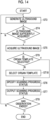
Fig. 14 is a flowchart showing an operation of the ultrasound diagnostic apparatus according to Embodiment 4 of the present invention. - Hereinafter, embodiments of the present invention will be described on the basis of the accompanying drawings.
- The configuration requirements are described later based on a representative embodiment of the present invention, but the present invention is not limited to such an embodiment.
- In the present specification, a numerical range represented by "to" means a range including numerical values described before and after "to" as a lower limit value and an upper limit value.
- In the present specification, "the same" includes an error range generally allowed in the technical field.
-
Fig. 1 shows a configuration of an ultrasound diagnostic apparatus according toEmbodiment 1 of the present invention. The ultrasound diagnostic apparatus comprises anultrasound probe 1, and anapparatus body 2 connected to theultrasound probe 1. Theultrasound probe 1 and theapparatus body 2 are connected to each other via so-called wired communication or so-called wireless communication. - The
ultrasound probe 1 includes atransducer array 11. Atransceiver circuit 12 is connected to thetransducer array 11. Theultrasound probe 1 includes aprobe tracking sensor 13. Theprobe tracking sensor 13 may be incorporated in theultrasound probe 1 or attached to a housing of theultrasound probe 1. In addition, in a case in which a sensor device, such as a so-called optical sensor, that measures theultrasound probe 1 from the outside is used as theprobe tracking sensor 13, theprobe tracking sensor 13 may be disposed at a position away from theultrasound probe 1. - The
apparatus body 2 includes animage generation unit 21 connected to thetransceiver circuit 12 of theultrasound probe 1. Adisplay controller 22 and amonitor 23 are sequentially connected to theimage generation unit 21. Animage memory 24 is connected to theimage generation unit 21. A three-dimensional ultrasoundimage generation unit 25 is connected to theimage memory 24. In addition, theapparatus body 2 comprises atemplate memory 26. Atemplate selection unit 27 is connected to thetemplate memory 26. Further, a scanning progressstatus output unit 28 is connected to the three-dimensional ultrasoundimage generation unit 25 and thetemplate selection unit 27. The scanning progressstatus output unit 28 is connected to thedisplay controller 22. Further, abody controller 29 is connected to theprobe tracking sensor 13, thetransceiver circuit 12, theimage generation unit 21, thedisplay controller 22, theimage memory 24, the three-dimensional ultrasoundimage generation unit 25, thetemplate memory 26, thetemplate selection unit 27, and the scanning progressstatus output unit 28. Aninput device 30 is connected to thebody controller 29. - The
transceiver circuit 12, theimage generation unit 21, and the three-dimensional ultrasoundimage generation unit 25 constitute a three-dimensional ultrasoundimage acquisition unit 31. In addition, theimage generation unit 21, thedisplay controller 22, the three-dimensional ultrasoundimage generation unit 25, thetemplate selection unit 27, the scanning progressstatus output unit 28, and thebody controller 29 constitute aprocessor 32 for theapparatus body 2. - The
transducer array 11 of theultrasound probe 1 includes a plurality of ultrasound transducers arranged one-dimensionally or two-dimensionally. In response to a drive signal supplied from thetransceiver circuit 12, each of the ultrasound transducers transmits ultrasound and receives an ultrasound echo from a subject to output a signal based on the ultrasound echo. For example, each ultrasound transducer is configured by forming electrodes at both ends of a piezoelectric material consisting of piezoelectric ceramic represented by lead zirconate titanate (PZT), a polymer piezoelectric element represented by poly vinylidene di fluoride (PVDF), piezoelectric single crystal represented by lead magnesium niobate-lead titanate (PMN-PT), and the like. - The three-dimensional ultrasound
image acquisition unit 31 configured by thetransceiver circuit 12, theimage generation unit 21, and the three-dimensional ultrasoundimage generation unit 25 acquires a three-dimensional ultrasound image of an organ of the subject by transmitting and receiving an ultrasound beam using theultrasound probe 1. A method of acquiring the three-dimensional ultrasound image will be described later. - Under the control of the
body controller 29, thetransceiver circuit 12 causes thetransducer array 11 to transmit the ultrasound and generates a sound ray signal based on a reception signal acquired by thetransducer array 11. As shown inFig. 2 , thetransceiver circuit 12 includes apulser 41 connected to thetransducer array 11, and an amplifyingunit 42, an analog-to-digital (AD)conversion unit 43, and a beam former 44 that are sequentially connected in series to thetransducer array 11. - The
pulser 41 includes, for example, a plurality of pulse generators, and thepulser 41 adjusts an amount of delay of each drive signal such that the ultrasound transmitted from the plurality of ultrasound transducers of thetransducer array 11 form the ultrasound beam, based on a transmission delay pattern selected in accordance with a control signal from thebody controller 29, and supplies the adjusted signal to the plurality of ultrasound transducers. In this way, in a case in which a pulsed or continuous wave-like voltage is applied to the electrodes of the ultrasound transducer of thetransducer array 11, the piezoelectric material expands and contracts to generate pulsed or continuous wave-like ultrasound from each of the ultrasound transducers, whereby the ultrasound beam is formed from the combined wave of the ultrasound. - The transmitted ultrasound beam is, for example, reflected in a target such as a part of the subject and propagates toward the
transducer array 11 of theultrasound probe 1. The ultrasound echo propagating toward thetransducer array 11 in this way is received by each of the ultrasound transducers constituting thetransducer array 11. In this case, each of the ultrasound transducers constituting thetransducer array 11 receives the propagating ultrasound echo to expand and contract to generate the reception signal, which is an electrical signal, and outputs these reception signals to the amplifyingunit 42. - The amplifying
unit 42 amplifies the signal input from each of the ultrasound transducers constituting thetransducer array 11 and transmits the amplified signal to theAD conversion unit 43. TheAD conversion unit 43 converts the signal transmitted from the amplifyingunit 42 into digital reception data. The beam former 44 performs so-called reception focus processing by applying and adding the delay to each reception data received from theAD conversion unit 43. By this reception focus processing, each reception data converted by theAD conversion unit 43 is phase-added, and the sound ray signal in which the focus of the ultrasound echo is narrowed down is acquired. - As shown in
Fig. 3 , theimage generation unit 21 has a configuration in which asignal processing unit 45, a digital scan converter (DSC) 46, and animage processing unit 47 are sequentially connected in series to each other. - The
signal processing unit 45 generates a B-mode image signal, which is tomographic image information related to tissues inside the subject, by performing, on the sound ray signal received from thetransceiver circuit 12, correction of the attenuation due to a distance in accordance with a depth of a reflection position of the ultrasound by using a sound velocity value set by thebody controller 29 and then performing envelope detection processing. - The
DSC 46 converts (raster-converts) the B-mode image signal generated by thesignal processing unit 45 into the image signal in accordance with a normal television signal scanning method. - The
image processing unit 47 performs various types of necessary image processing such as gradation processing on the B-mode image signal input from theDSC 46, and then transmits the B-mode image signal to thedisplay controller 22 and theimage memory 24. Hereinafter, the B-mode image signal that is image-processed by theimage processing unit 47 will be referred to as an ultrasound image. - The
probe tracking sensor 13 is a sensor device that acquires position/posture information of theultrasound probe 1 under the control of thebody controller 29. Here, in general, in a case in which the user performs an examination on the subject using the ultrasound diagnostic apparatus, the user often performs the examination while changing the posture of theultrasound probe 1, that is, an inclination angle and a rotation angle of theultrasound probe 1 in a state in which theultrasound probe 1 is in contact with a body surface of the subject and moving the position of theultrasound probe 1. The position/posture information of theultrasound probe 1 acquired by theprobe tracking sensor 13 includes information on the posture and the position of theultrasound probe 1. Theprobe tracking sensor 13 can include, for example, at least one of a so-called inertial sensor, a magnetic sensor, an optical sensor, or an optical camera. The inertial sensor can include, for example, at least one of a so-called acceleration sensor or a gyro sensor. - The
image memory 24 is a memory in which the ultrasound image generated by theimage generation unit 21, the position/posture information of theultrasound probe 1 acquired by theprobe tracking sensor 13, and the three-dimensional ultrasound image acquired by the three-dimensional ultrasoundimage acquisition unit 31 are stored. Here, as theimage memory 24, for example, a recording medium such as a flash memory, a hard disk drive (HDD), a solidstate drive (SSD), a flexible disk (FD), a magneto-optical disk (MO disk), a magnetic tape (MT), a random-access memory (RAM), a compact disc (CD), a digital versatile disc (DVD), a secure digital card (SD card), or a universal serial bus memory (USB memory) can be used. - Here, the ultrasound image generated by the
image generation unit 21 and the position/posture information of theultrasound probe 1 acquired by theprobe tracking sensor 13 in a case in which the ultrasound image is generated are stored in theimage memory 24 in association with each other. - The three-dimensional ultrasound
image generation unit 25 generates the three-dimensional ultrasound image of the organ of the subject based on the ultrasound images of a plurality of frames generated by theimage generation unit 21. The three-dimensional ultrasoundimage generation unit 25 can generate the three-dimensional ultrasound image of the organ, for example, by arranging the ultrasound images of the plurality of frames in accordance with the position/posture information of thecorresponding ultrasound probe 1. - It should be noted that the three-dimensional ultrasound
image generation unit 25 can sequentially perform processing of generating the three-dimensional ultrasound image each time the ultrasound image is generated by theimage generation unit 21. In addition, the three-dimensional ultrasoundimage generation unit 25 can also perform processing of collectively generating a three-dimensional ultrasound image for the ultrasound images of a certain number of a plurality of frames stored in theimage memory 24. - The
template memory 26 is a memory in which a plurality of organ templates for a specific organ of the subject are stored. The plurality of organ templates represent a plurality of three-dimensional shapes of the organ deformed in accordance with a posture of the subject, such as a so-called sitting posture, decubitus posture, ventral decubitus posture, or lateral decubitus posture. That is, thetemplate memory 26 stores, for the specific organ, the plurality of organ templates corresponding to the posture of the subject, such as an organ template corresponding to the sitting posture, an organ template corresponding to the decubitus posture, an organ template corresponding to the ventral decubitus posture, and an organ template corresponding to the lateral decubitus posture. It should be noted that, as the organ template corresponding to the lateral decubitus posture, both the organ templates of a left lateral decubitus posture in which the subject lies on a left side and a right lateral decubitus posture in which the subject lies on a right side can be used. - For example, in a case in which the
template memory 26 stores an organ template of a liver, thetemplate memory 26 stores an organ template M1 representing a reference shape of the liver in the anatomy as shown inFig. 4 , as well as an organ template M2 representing a shape of the liver deformed from the reference shape by the application of an external force in accordance with a specific posture of the subject as shown inFig. 5 . - In addition, each of the plurality of organ templates stored in the
template memory 26 may consist of three-dimensional data representing a contour of the organ in accordance with the posture of the subject, or may consist of three-dimensional data representing the contour of the organ and an internal structure of the organ in accordance with the posture of the subject. - As the
template memory 26, for example, a recording medium such as a flash memory, an HDD, an SSD, an FD, an MO disk, an MT, a RAM, a CD, a DVD, an SD card, or a USB memory can be used. - The
template selection unit 27 selects one organ template from among the plurality of organ templates stored in thetemplate memory 26 in accordance with the posture of the subject. Here, the posture of the subject can be input by, for example, the user of the ultrasound diagnostic apparatus, such as a doctor, via theinput device 30. For example, in a case in which the organ as an observation target is the liver and the sitting posture is input by the user as the posture of the subject, thetemplate selection unit 27 can select the organ template of the liver corresponding to the sitting posture. - The scanning progress
status output unit 28 specifies a scanning progress status of theultrasound probe 1 for the organ as the observation target by performing registration between the three-dimensional ultrasound image acquired by the three-dimensional ultrasoundimage acquisition unit 31 and one organ template selected by thetemplate selection unit 27, and outputs the specified scanning progress status. - The scanning progress
status output unit 28 can perform the registration between the three-dimensional ultrasound image and one organ template by, for example, an algorithm such as a so-called random sample consensus (RANSAC) or an iterative closest point (ICP), a so-called machine learning method, or a combination thereof. It should be noted that the processing of the registration can include, for example, processing of deforming the three-dimensional ultrasound image or one organ template. - Here, the scanning progress status of the
ultrasound probe 1 indicates a progress degree of the scanning using theultrasound probe 1 for the organ as the observation target. The scanning progressstatus output unit 28 can specify a region that has been scanned using theultrasound probe 1 in the organ as the observation target as the scanning progress status, to display the region that has been scanned, on themonitor 23. For example, in a case in which the organ as the observation target is the liver, the scanning progressstatus output unit 28 can display a region R1 that has been scanned, on themonitor 23 in a state of being superimposed on the organ template of the liver selected by thetemplate selection unit 27 as shown inFig. 6 . This example shows that the scanning of a part of a right lobe A1 of the liver is completed out of the right lobe A1 and a left lobe A2. - In addition, the scanning progress
status output unit 28 can specify a region of the organ as the observation target that has not yet been scanned using theultrasound probe 1 as the scanning progress status, to display the region that has not yet been scanned, on themonitor 23. For example, in a case in which the organ as the observation target is the liver, the scanning progressstatus output unit 28 can display a region R2 that has not yet been scanned, on themonitor 23 in a state of being superimposed on the organ template of the liver selected by thetemplate selection unit 27 as shown inFig. 7 . This example shows that the scanning of a part of the right lobe A1 and the entire left lobe A2 of the liver is not completed out of the right lobe A1 and the left lobe A2. - The
display controller 22 performs predetermined processing on the ultrasound image transmitted from theimage generation unit 21, the scanning progress status of theultrasound probe 1 output by the scanning progressstatus output unit 28, and the like, and displays the ultrasound image, the scanning progress status, and the like on themonitor 23, under the control of thebody controller 29. - The
monitor 23 is a monitor for displaying the ultrasound image, the scanning progress status, and the like under the control of thedisplay controller 22, and includes a display device such as a liquid crystal display (LCD), or an organic electroluminescence (EL) display. - The
body controller 29 controls the respective units of theapparatus body 2, thetransceiver circuit 12 of theultrasound probe 1, and theprobe tracking sensor 13 based on a control program and the like stored in advance. - The
input device 30 is an input device for the user to perform an input operation, and is configured by, for example, a device such as a keyboard, a mouse, a trackball, a touchpad, and a touch sensor disposed in a state of being superimposed on themonitor 23. - It should be noted that the
processor 32 including theimage generation unit 21, thedisplay controller 22, the three-dimensional ultrasoundimage generation unit 25, thetemplate selection unit 27, the scanning progressstatus output unit 28, and thebody controller 29 is configured by a central processing unit (CPU) and the control program for causing the CPU to execute various types of processing, but theprocessor 32 may be configured by a field programmable gate array (FPGA), a digital signal processor (DSP), an application specific integrated circuit (ASIC), a graphics processing unit (GPU), or other integrated circuits (IC), or may be configured by a combination thereof. - In addition, the
image generation unit 21, thedisplay controller 22, the three-dimensional ultrasoundimage generation unit 25, thetemplate selection unit 27, the scanning progressstatus output unit 28, and thebody controller 29 can also be configured by being integrated partially or entirely into one CPU or the like. - Next, an operation of the ultrasound diagnostic apparatus according to
Embodiment 1 will be described with reference to the flowchart shown inFig. 8 . Hereinafter, a case will be described in which the organ as the observation target of the subject is the liver. - In step ST1, the posture of the subject is input by the user via the
input device 30. In this case, thebody controller 29 receives the posture of the subject input by the user. - In step ST2, the
template selection unit 27 selects one organ template corresponding to the posture of the subject which is input by the user in step ST1 and received by thebody controller 29, from among the plurality of organ templates of the liver stored in thetemplate memory 26. - In step ST3, the
image generation unit 21 generates the ultrasound image of the liver of the subject. In this case, under the control of thebody controller 29, the transmission and reception of the ultrasound from the plurality of transducers of thetransducer array 11 are started in accordance with the drive signal from thepulser 41 of thetransceiver circuit 12 of theultrasound probe 1, the ultrasound echo from the subject is received by the plurality of transducers of thetransducer array 11, and the reception signal as the analog signal is output to the amplifyingunit 42, is amplified, and then is subjected to the AD conversion via theAD conversion unit 43 to acquire the reception data. - The reception focus processing is performed on the reception data by the beam former 44, and the sound ray signal generated by the reception focusing processing is transmitted to the
image generation unit 21 of theapparatus body 2, thereby the ultrasound image representing the tomographic image information of the subject is generated by theimage generation unit 21. In this case, thesignal processing unit 45 of theimage generation unit 21 performs the correction of the attenuation in accordance with the depth of the reflection position of the ultrasound and the envelope detection processing on the sound ray signal, theDSC 46 performs the conversion into the image signal in accordance with the normal television signal scanning method, and theimage processing unit 47 performs various types of necessary image processing such as gradation processing. The ultrasound image generated in step ST3 in this way is displayed on themonitor 23 via thedisplay controller 22. - In a case in which the ultrasound image is generated in step ST3, the
probe tracking sensor 13 acquires the position/posture information of theultrasound probe 1. The ultrasound image generated in step ST3 and the acquired position/posture information of theultrasound probe 1 are stored in theimage memory 24 in association with each other. - In step ST4, the
body controller 29 determines whether or not the ultrasound image is sufficiently acquired in the generation of the three-dimensional ultrasound image. Thebody controller 29 can determine whether or not the ultrasound image is sufficiently acquired, for example, by determining whether or not a predetermined time has elapsed since the start of step ST1. More specifically, for example, thebody controller 29 can determine that the ultrasound image can be sufficiently acquired in a case in which the predetermined time has elapsed since the start ofstep ST 1, and can determine that the ultrasound image cannot be sufficiently acquired in a case in which the predetermined time has not yet elapsed. - In addition, the
body controller 29 can also determine whether or not the ultrasound image is sufficiently acquired by determining whether or not the movement of theultrasound probe 1 is stopped after being moved by the user, for example, with reference to the position/posture information acquired in step ST3. More specifically, for example, thebody controller 29 can determine that the ultrasound image can be sufficiently acquired in a case in which the movement of theultrasound probe 1 is stopped after being moved by the user, and can determine that the ultrasound image cannot be sufficiently acquired in a case in which theultrasound probe 1 continues to move. - In a case in which it is determined in step ST4 that the ultrasound image used for the generation of the three-dimensional ultrasound image is not sufficiently acquired, the processing returns to step ST3, the ultrasound image is newly generated, and the ultrasound image is stored in the
image memory 24 along with the position/posture information of theultrasound probe 1. In this way, the pieces of processing of steps ST3 and ST4 are repeated until it is determined in step ST4 that the ultrasound image is sufficiently acquired. - In a case in which it is determined in step ST4 that the ultrasound image to be used for the generation of the three-dimensional ultrasound image is sufficiently acquired, the processing proceeds to step ST5. In step ST5, the three-dimensional ultrasound
image generation unit 25 generates the three-dimensional ultrasound image of the liver of the subject based on a plurality of pieces of the position/posture information of theultrasound probe 1 and the ultrasound images of the plurality of frames obtained by repeating step ST3 and step ST4. In this case, for example, the three-dimensional ultrasoundimage generation unit 25 can generate the three-dimensional ultrasound image of the liver by arranging the ultrasound images of the plurality of frames in accordance with the position/posture information of theultrasound probe 1 associated with each ultrasound image. - In step ST6, the scanning progress
status output unit 28 specifies the scanning progress status of theultrasound probe 1 with respect to the liver by performing the registration between one organ template selected in step ST2 and the three-dimensional ultrasound image of the liver acquired in step ST5 by using an algorithm such as RANSAC and ICP, a machine learning method, a combination thereof, or the like. - In this way, since the organ template representing the shape of the liver corresponding to the posture of the subj ect is used for the registration with the three-dimensional ultrasound image of the liver, even in a case in which the liver of the subject is deformed due to the posture of the subject, the three-dimensional ultrasound image can be accurately registered with the organ template. As a result, for example, the region R1 that has been scanned or the region R2 that has not yet been scanned in the liver can be accurately specified as the scanning progress status of the
ultrasound probe 1. - In step ST7, the scanning progress
status output unit 28 outputs the scanning progress status specified in step ST6. For example, as shown inFig. 6 or7 , the scanning progressstatus output unit 28 can display the region R1 that has been scanned or the region R2 that has not yet been scanned in the liver on themonitor 23 as the scanning progress status of theultrasound probe 1 in a state of being superimposed on one organ template selected in step ST2. - In step ST8, the
body controller 29 determines whether or not to end the observation of the liver of the subject. Thebody controller 29 can determine to end the observation of the liver in a case in which the user determines that the liver of the subject can be comprehensively observed by, for example, checking the scanning progress status output in step ST7 and inputs an instruction to end the observation via theinput device 30. Thebody controller 29 can determine to continue the observation of the liver in a case in which the user determines that the liver of the subject cannot be yet comprehensively observed by, for example, checking the scanning progress status output in step ST7 and does not input the instruction to end the observation. - The pieces of processing of step ST3 to step ST8 are repeated as long as it is determined to continue the observation of the liver in step ST8. In step ST3 in the repetition of steps ST3 to ST8, the three-dimensional ultrasound
image generation unit 25 adds the data corresponding to the newly acquired ultrasound images of the plurality of frames to the already acquired three-dimensional ultrasound image of the liver, to generate the three-dimensional ultrasound image of the liver. Therefore, the scanning progress status of theultrasound probe 1, which is specified in step ST6 and output in step ST7, is updated at any time by repeating step ST3 to step ST8. The user can continue the scanning while checking the scanning progress status of theultrasound probe 1 which is updated at any time by repeating steps ST3 to ST8, and thus can easily and accurately perform the comprehensive observation of the liver of the subject regardless of the skill level of the user. - In a case in which it is determined in step ST8 to end the observation of the liver, the operation of the ultrasound diagnostic apparatus according to the flowchart of
Fig. 8 is completed. - As described above, with the ultrasound diagnostic apparatus according to
Embodiment 1, thetemplate memory 26 stores the plurality of organ templates for the organ as the observation target, thetemplate selection unit 27 selects one organ template from among the plurality of organ templates in accordance with the posture of the subject, and the scanning progressstatus output unit 28 performs the registration between the acquired three-dimensional ultrasound image and the selected one organ template, specifies the scanning progress status of theultrasound probe 1 for the organ as the observation target, and outputs the specified scanning progress status, so that it is possible for the user to easily and accurately perform the comprehensive observation of the organ as the observation target regardless of the skill level. - It should be noted that the description has been made in which the
ultrasound probe 1 comprises thetransceiver circuit 12, but theapparatus body 2 may comprise thetransceiver circuit 12. - In addition, the description has been made in which the
apparatus body 2 comprises theimage generation unit 21, but theultrasound probe 1 may comprise theimage generation unit 21. - In addition, the
apparatus body 2 may be a so-called stationary type, a portable type that is easy to carry, or a so-called hand-held type configured by, for example, a smartphone or tablet computer. As described above, the type of the device constituting theapparatus body 2 is not particularly limited. - In addition, the scanning progress
status output unit 28 can output the scanning progress status for each section, for example, by dividing the organ as the observation target into a plurality of sections, quantifying the scanning progress status of theultrasound probe 1 in each of the plurality of sections, and outputting the quantified scanning progress status. For example, the scanning progressstatus output unit 28 can divide the liver of the subject into two sections of the right lobe A1 and the left lobe A2, and output a ratio of the region R1 that has been scanned or a ratio of the region R2 that has not yet been scanned, in each section in, for example, a percentage such as "right lobe: ∘∘%, left lobe: ∘∘%". - In addition, for example, the scanning progress
status output unit 28 can also divide the liver into four sections of a rear section T1, an front section T2, an inner section T3, and an outer section T4 as shown inFig. 9 , or can also divide the liver into eight sub-sections S1 to S8 (sub-section S1 is not shown because the sub-section S1 is inside the liver) as shown inFig. 10 . - The scanning progress
status output unit 28 can display the scanning progress status specified in this way for each of the plurality of sections on themonitor 23 as, for example, a numerical value. The scanning progressstatus output unit 28 can also display the scanning progress status specified for each of the plurality of sections on themonitor 23, for example, by displaying a so-called progress bar on themonitor 23. In addition, in a case in which the ultrasound diagnostic apparatus includes a speaker (not shown), the scanning progressstatus output unit 28 can also output the scanning progress status specified for each of the plurality of sections as a voice, for example, via the speaker. - In addition, the scanning progress
status output unit 28 can output a section in which further scanning using theultrasound probe 1 is recommended among the plurality of sections based on the quantified scanning progress statuses of theultrasound probe 1 in the plurality of sections. The scanning progressstatus output unit 28 can output, for example, a section having the lowest ratio of the region R1 that has been scanned (section having the highest ratio of the region R2 that has not yet been scanned) among the plurality of sections of the organ as the observation target, as the section for which further scanning is recommended. The user can understand the section in which the scanning is not sufficiently performed by checking the output of the section for which the further scanning is recommended. The user can easily and reliably perform the comprehensive observation by performing the scanning using theultrasound probe 1 comprehensively on the output sections while preferentially scanning the section in which the scanning is not sufficiently performed. - In addition, in general, it is known that, in a case in which a portion in which an object, such as a bone, through which it is difficult for the ultrasound to be transmitted is located is scanned using the
ultrasound probe 1, a so-called acoustic shadow is generated by the bone or the like in the captured ultrasound image. For example, the three-dimensional ultrasoundimage generation unit 25 can detect a region representing the acoustic shadow in the generated three-dimensional ultrasound image, and the scanning progressstatus output unit 28 can exclude the region representing the acoustic shadow from the region R1 that has been scanned or output the region representing the acoustic shadow as the region R2 that has not yet been scanned. Here, the three-dimensional ultrasoundimage generation unit 25 can detect the region representing the acoustic shadow in the three-dimensional ultrasound image by using, for example, a trained model in machine learning, which has learned a large number of ultrasound images including the acoustic shadow. - In this way, by excluding the region representing the acoustic shadow from the region R1 that has been scanned or outputting the region representing the acoustic shadow as the region R2 that has not yet been scanned, the scanning progress status of the
ultrasound probe 1 can be more accurately output, and thus the user can more reliably perform the comprehensive observation of the organ as the observation target. - In addition, in general, it is known that, in a state of so-called aerial radiation, that is, in a state in which the
ultrasound probe 1 is separated from the body surface of the subject and the ultrasound are radiated from theultrasound probe 1 into the air, for example, an aerial radiation image, which is an ultrasound image in which the entire image is filled with a specific color such as black, is obtained. Thebody controller 29 can determine whether or not the aerial radiation image is generated by determining, for example, whether or not the entire ultrasound image generated by theimage generation unit 21 is filled with the specific color such as black, and can determine that the observation of the organ as the observation target is stopped in a case in which it is determined that the aerial radiation image is generated. In this case, thebody controller 29 can stop, for example, the processing of the three-dimensional ultrasoundimage generation unit 25. - As a result, it is possible to prevent the aerial radiation image from being added in a case of generating the three-dimensional ultrasound image, and the scanning progress
status output unit 28 can more accurately output the scanning progress status of theultrasound probe 1, so that the user can more reliably perform the comprehensive observation of the organ as the observation target. - In addition, a landmark, which is a portion having significant shape characteristics, may be present in the organ of the subject. For example, a branch point of a portal vein or an inferior vena cava is described as the landmark of the liver. In a case in which the three-dimensional ultrasound image of the landmark in the organ as the observation target can be accurately acquired, the three-dimensional ultrasound image of the organ as the observation target deformed by the posture of the subject can be more accurately acquired.
- Therefore, the
body controller 29 can issue an instruction to the user by, for example, displaying on themonitor 23 that pre-scanning for drawing the landmark, which is a portion that is likely to be greatly deformed in accordance with the posture of the subject, in the organ is performed before the user performs main scanning of the organ as the observation target, that is, the comprehensive observation of the entire organ as the observation target. In this case, the three-dimensional ultrasoundimage generation unit 25 can generate the three-dimensional ultrasound image of the landmark of the organ as the observation target. Thebody controller 29 determines whether or not a structure of the generated three-dimensional ultrasound image of the landmark is defective, for example, whether or not the shape of the three-dimensional ultrasound image of the portal vein, which is the landmark, is smoothly continuous, and can end the pre-scanning and start the main scanning in a case in which it is determined that the structure of the three-dimensional ultrasound image of the landmark is not defective. - Although it has been described that the three-dimensional ultrasound
image generation unit 25 generates the three-dimensional ultrasound image based on the position/posture information of theultrasound probe 1 acquired by theprobe tracking sensor 13 and the ultrasound images of the plurality of frames generated by theimage generation unit 21, the method of generating the three-dimensional ultrasound image is not particularly limited to this. - For example, in a case in which the ultrasound images of the plurality of frames are generated while the
ultrasound probe 1 is moved in parallel in a certain direction or while theultrasound probe 1 is inclined in a certain angle range while theultrasound probe 1 is disposed at a fixed position, the three-dimensional ultrasoundimage generation unit 25 can generate the three-dimensional ultrasound image by arranging the ultrasound images of the plurality of frames generated by theimage generation unit 21 in time series without using the position/posture information of theultrasound probe 1 acquired by theprobe tracking sensor 13. - In addition, in a case in which the
transducer array 11 includes the plurality of ultrasound transducers arranged in a two-dimensional manner, thetransceiver circuit 12 can acquire the ultrasound images of the plurality of frames by performing so-called electronic scanning. In this case, the three-dimensional ultrasoundimage generation unit 25 can generate the three-dimensional ultrasound image from the acquired ultrasound images of a plurality of frames based on a positional relationship of a plurality of tomographic planes scanned by electronic scanning. - In
Embodiment 1, the description has been made in which the user inputs the posture of the subject via theinput device 30, but the ultrasound diagnostic apparatus can also automatically detect the posture of the subject. -
Fig. 11 shows a configuration of an ultrasound diagnostic apparatus according toEmbodiment 2. The ultrasound diagnostic apparatus according toEmbodiment 2 comprises anapparatus body 2A instead of theapparatus body 2 and further comprises anoptical camera 51, with respect to the ultrasound diagnostic apparatus according toEmbodiment 1 shown inFig. 1 . Although theoptical camera 51 is provided outside theultrasound probe 1 and theapparatus body 2A, for example, theoptical camera 51 may be attached to or incorporated in theapparatus body 2A. - The
apparatus body 2A comprises abody controller 29A instead of thebody controller 29 and further comprises an opticalimage analysis unit 52, in theapparatus body 2 according toEmbodiment 1. Here, the opticalimage analysis unit 52 is connected to theoptical camera 51. The opticalimage analysis unit 52 is connected to thetemplate selection unit 27 and thebody controller 29A. Theoptical camera 51 and the opticalimage analysis unit 52 constitute aposture detection unit 53. In addition, in theapparatus body 2A, theimage generation unit 21, thedisplay controller 22, the three-dimensional ultrasoundimage generation unit 25, thetemplate selection unit 27, the scanning progressstatus output unit 28, thebody controller 29A, and the opticalimage analysis unit 52 constitute aprocessor 32A for theapparatus body 2A. - The
optical camera 51 includes, for example, an image sensor such as a so-called chargecoupled device (CCD) image sensor or a so-called a complementary metal-oxide-semiconductor (CMOS) image sensor, and images the subject to acquire an optical image. Theoptical camera 51 transmits the acquired optical image to the opticalimage analysis unit 52. - The optical
image analysis unit 52 analyzes the optical image acquired by theoptical camera 51, to detect the posture of the subject. The opticalimage analysis unit 52 can detect the posture of the subject from the optical image, for example, by a method of using a trained model in machine learning, which has learned a relationship between the optical image in which the subject is shown and the posture of the subject. - The
template selection unit 27 selects one organ template corresponding to the posture of the subject detected by the opticalimage analysis unit 52 from among the plurality of organ templates stored in thetemplate memory 26 for the organ as the observation target. - The
template selection unit 27 can calculate a degree of similarity with respect to the posture of the subject detected by theposture detection unit 53 for each of the plurality of organ templates stored in thetemplate memory 26, for example, and select one organ template having the highest degree of similarity. In this case, thetemplate selection unit 27 can calculate the degree of similarity by using, for example, an algorithm such as a so-called support-vector machine (SVM), a decision tree, deep learning, or collaborative filtering, or a combination of these algorithms. - In addition, the
template selection unit 27 can also select one organ template by using, for example, a trained model in machine learning, which has learned a relationship between a detection result, which is the output from theposture detection unit 53 in accordance with the posture of the subject, and the organ template. - The scanning progress
status output unit 28 specifies the scanning progress status of theultrasound probe 1 by performing registration between the three-dimensional ultrasound image generated by the three-dimensional ultrasoundimage generation unit 25 and one organ template selected by thetemplate selection unit 27, and outputs the specified scanning progress status. - As described above, with the ultrasound diagnostic apparatus according to
Embodiment 2, theposture detection unit 53 configured by theoptical camera 51 and the opticalimage analysis unit 52 automatically detects the posture of the subject from the optical image of the subject, so that the user does not need to input the posture of the subject via theinput device 30, and can more easily perform the comprehensive observation of the organ of the subject. - It should be noted that the optical image of the subject captured by the
optical camera 51 may be an image in which the entire body of the subject is imaged, or an image in which the subject is partially imaged, for example, only the upper body of the subject is imaged. The opticalimage analysis unit 52 can detect the posture of the subject based on the optical image obtained by imaging the entire body of the subject or the optical image obtained by partially imaging the subject by using, for example, a trained model in machine learning, which has learned a relationship between the optical image of the subject and the posture of the subject. - In addition, for example, in a case in which the degree of similarity of the posture of the subject is used for the selection of the organ template, a plurality of calculated degrees of similarity are very close to each other, and a difference thereof is within a certain value, the
template selection unit 27 can also display the plurality of organ templates that may be used by the scanning progressstatus output unit 28, on themonitor 23. In this case, thetemplate selection unit 27 can select, for example, one organ template designated by the user via theinput device 30 from among the plurality of organ templates displayed on themonitor 23. In addition, thetemplate selection unit 27 can select one organ template designated by the user in the same manner, for example, even in a case in which a trained model in machine learning is used for selecting the organ template and the trained model outputs the plurality of organ templates. - In addition, instead of the optical image of the subject acquired by the
optical camera 51, for example, a signal related to the position of the body of the subject can be acquired by a sensor device such as an optical sensor, an infrared camera, an infrared sensor, a magnetic sensor, or light detection and ranging (LiDAR) (which are not shown), and the posture of the subject can be detected by analyzing the signal. In this case, a signal analysis unit (not shown) that analyzes the signal related to the position of the body of the subject can detect the posture of the subject from the signal related to the position of the body of the subject by using, for example, a method of comparing the acquired signal with a template of a signal indicating a plurality of postures of the subject, or a method of using a trained model in machine learning, which has learned a relationship between the signal and the posture of the subject. - The ultrasound diagnostic apparatus can also detect the posture of the subject based on a signal from a pressure sensor disposed on an examination table on which the subject is placed in a case in which the subject undergoes the examination. Here, the examination table according to the embodiment of the present invention includes a chair, a bed, and the like on which the subject is placed during the examination.
-
Fig. 12 shows a configuration of an ultrasound diagnostic apparatus according to Embodiment 3. The ultrasound diagnostic apparatus according to Embodiment 3 comprises anapparatus body 2B instead of theapparatus body 2A and comprises a plurality ofpressure sensors 54 disposed on an examination table B instead of theoptical camera 51 in the ultrasound diagnostic apparatus ofEmbodiment 2 shown inFig. 11 . Theapparatus body 2B comprises abody controller 29B instead of thebody controller 29A and comprises asignal analysis unit 55 instead of the opticalimage analysis unit 52 in theapparatus body 2A according toEmbodiment 2. - The
signal analysis unit 55 is connected to the plurality ofpressure sensors 54 disposed on the examination table B. Thesignal analysis unit 55 is connected to thetemplate selection unit 27 and thebody controller 29B. The plurality ofpressure sensors 54 and thesignal analysis unit 55 constitute aposture detection unit 56. In addition, in theapparatus body 2B, theimage generation unit 21, thedisplay controller 22, the three-dimensional ultrasoundimage generation unit 25, thetemplate selection unit 27, the scanning progressstatus output unit 28, thebody controller 29B, and thesignal analysis unit 55 constitute aprocessor 32B for theapparatus body 2B. - The plurality of
pressure sensors 54 are disposed on the examination table B on which the subject is placed in a case in which the subject undergoes the examination, and detect a detection signal representing a distribution of pressure from the subject, which correspond to the posture of the subject. Since a shape and an area of a region in which the subject touches the bed vary depending on the posture of the subject on the bed, the detection signal representing the distribution of pressure corresponding to each posture of the subject is detected by the plurality ofpressure sensors 54. - The
signal analysis unit 55 analyzes the detection signals acquired by the plurality ofpressure sensors 54, to detect the posture of the subject. Thesignal analysis unit 55 can store, for example, templates of a plurality of detection signals corresponding to a plurality of postures of the subject in advance, to detect the posture of the subject by comparing the detection signals acquired by the plurality ofpressure sensors 54 with the templates. In addition, thesignal analysis unit 55 can also detect the posture of the subject by using a trained model in machine learning, which has learned a relationship between the posture of the subject and the detection signal. - The
template selection unit 27 selects one organ template corresponding to the posture of the subject detected by thesignal analysis unit 55 from among the plurality of organ templates stored in thetemplate memory 26 for the organ as the observation target. - The
template selection unit 27 can calculate a degree of similarity with respect to the posture of the subject detected by theposture detection unit 56 for each of the plurality of organ templates stored in thetemplate memory 26, for example, and select one organ template having the highest degree of similarity. In this case, thetemplate selection unit 27 can calculate the degree of similarity by using, for example, an algorithm such as a so-called SVM, a decision tree, deep learning, or collaborative filtering, or a combination of these algorithms. - In addition, the
template selection unit 27 can also select one organ template by using, for example, a trained model in machine learning, which has learned a relationship between a detection result, which is the output from theposture detection unit 56 in accordance with the posture of the subject, and the organ template. - The scanning progress
status output unit 28 specifies the scanning progress status of theultrasound probe 1 by performing registration between the three-dimensional ultrasound image generated by the three-dimensional ultrasoundimage generation unit 25 and one organ template selected by thetemplate selection unit 27, and outputs the specified scanning progress status. - As described above, with the ultrasound diagnostic apparatus according to Embodiment 3, the
posture detection unit 56 configured by the plurality ofpressure sensors 54 and thesignal analysis unit 55 automatically detects the posture of the subject from the detection signal of the pressure, so that the user does not need to input the posture of the subject via theinput device 30, and can more easily perform the comprehensive observation of the organ of the subject, as in the ultrasound diagnostic apparatus according toEmbodiment 2. - It should be noted that, although it has been described that the plurality of
pressure sensors 54 are disposed on the examination table B, for example, in a case in which the examination table B is the chair, onepressure sensor 54 can be disposed on the chair. Since the posture of the subject placed on the chair is usually the sitting posture, thesignal analysis unit 55 can detect the posture of the subject as the sitting posture in a case in which the detection signal of the pressure is received from thepressure sensor 54. In this way, the ultrasound diagnostic apparatus can comprise at least onepressure sensor 54 disposed on the chair or the examination table B. - For example, in a case in which there are a plurality of examination tables B in an examination room for examining the subject, the
pressure sensor 54 can be disposed on each examination table B. - Although, in
Embodiments 1 to 3, thetemplate selection unit 27 selects one organ template for the organ as the observation target based on the information indicating the posture of the subject, for example, one organ template can also be selected based on the three-dimensional ultrasound image of the organ as the observation target. -
Fig. 13 shows a configuration of an ultrasound diagnostic apparatus according to Embodiment 4. The ultrasound diagnostic apparatus according to Embodiment 4 comprises an apparatus body 2C instead of theapparatus body 2 in the ultrasound diagnostic apparatus according toEmbodiment 1 shown inFig. 1 . The apparatus body 2C comprises atemplate selection unit 27C instead of thetemplate selection unit 27 and comprises abody controller 29C instead of thebody controller 29 in theapparatus body 2 according toEmbodiment 1. - In the apparatus body 2C, a
template selection unit 27C is connected to the three-dimensional ultrasoundimage generation unit 25 and thetemplate memory 26. Thetemplate selection unit 27C is connected to the scanning progressstatus output unit 28 and thebody controller 29C. In addition, theimage generation unit 21, thedisplay controller 22, the three-dimensional ultrasoundimage generation unit 25, thetemplate selection unit 27C, the scanning progressstatus output unit 28, and thebody controller 29C constitute aprocessor 32C for the apparatus body 2C. - The
template selection unit 27C selects one organ template based on the three-dimensional ultrasound image of the organ as the observation target acquired by the three-dimensional ultrasoundimage acquisition unit 31. For example, thetemplate selection unit 27C can calculate a degree of similarity with respect to the three-dimensional ultrasound image acquired by the three-dimensional ultrasoundimage acquisition unit 31 for each of the plurality of organ templates stored in thetemplate memory 26 for the organ as the observation target, and can select one organ template having the highest degree of similarity. In this case, thetemplate selection unit 27C can calculate the degree of similarity by using, for example, an algorithm such as an SVM, a decision tree, deep learning, or collaborative filtering, or a combination of these algorithms. - In addition, the
template selection unit 27C can also select one organ template by using, for example, a trained model in machine learning, which has learned the three-dimensional ultrasound image of the organ as the observation target in accordance with the posture of the subj ect. - The scanning progress
status output unit 28 specifies the scanning progress status of theultrasound probe 1 by performing registration between one organ template selected by thetemplate selection unit 27C and the three-dimensional ultrasound image generated by the three-dimensional ultrasoundimage generation unit 25, and outputs the specified scanning progress status. - Next, an example of an operation of the ultrasound diagnostic apparatus according to Embodiment 4 will be described with reference to the flowchart of
Fig. 14 . Steps ST3 to ST8 in the flowchart ofFig. 14 are the same as steps ST3 to ST8 inFig. 8 , and thus detailed description of these steps will be omitted. In addition, an example will be described in which the organ as the observation target is the liver. - First, in step ST3, the
image generation unit 21 generates the ultrasound image of the liver of the subject. In this case, theprobe tracking sensor 13 also acquires the position/posture information of theultrasound probe 1, and the ultrasound image and the position/posture information of theultrasound probe 1 corresponding to each other are stored in theimage memory 24 in association with each other. - In step ST4, the
body controller 29C determines whether or not the ultrasound image for generating the three-dimensional ultrasound image is sufficiently acquired. Here, the pieces of processing of steps ST3 and of ST4 are repeated until it is determined that the ultrasound image is sufficiently acquired. In a case in which it is determined in step ST4 that the ultrasound image for generating the three-dimensional ultrasound image is sufficiently acquired, the processing proceeds to step ST4. - In step ST5, the three-dimensional ultrasound
image generation unit 25 generates the three-dimensional ultrasound image of the liver based on the ultrasound images of the plurality of frames obtained by repeating steps ST3 and ST4 and stored in theimage memory 24. - In step ST9 following step ST5, the
body controller 29C determines whether or not one organ template for the liver as the observation target is already selected. At this point in time, since one organ template is not yet selected, thebody controller 29C determines that one organ template is not selected. In this case, the processing proceeds to step ST10. - In step ST10, the
template selection unit 27C calculates the degree of similarity of each of the plurality of organ templates with respect to the liver stored in theimage memory 24 to the three-dimensional ultrasound image of the liver acquired in step ST5, and selects one organ template having the highest degree of similarity. In this case, thetemplate selection unit 27C can calculate the degree of similarity by using, for example, an algorithm such as an SVM, a decision tree, deep learning, or collaborative filtering, or a combination of these algorithms. - In addition, the
template selection unit 27C can also select one organ template by using, for example, a trained model in machine learning, which has learned the three-dimensional ultrasound image of the organ as the observation target in accordance with the posture of the subj ect. - In step ST6 following step ST10, the scanning progress
status output unit 28 specifies the scanning progress status of theultrasound probe 1 with respect to the liver by performing registration between the three-dimensional ultrasound image of the liver acquired in step ST4 and one organ template selected in step ST9 by using an algorithm such as RANSAC and ICP, a machine learning method, a combination thereof, or the like. - In step ST7, the scanning progress
status output unit 28 outputs the scanning progress status specified in step ST6. - In step ST8, the
body controller 29C determines whether or not to end the observation of the liver of the subject. In a case in which it is determined to continue the observation of the liver in step ST8, the processing returns to step ST3. The ultrasound image of the liver of the subject is generated in step ST3, and it is determined in step ST4 whether or not the ultrasound image for generating the three-dimensional ultrasound image is sufficiently acquired. In a case in which it is determined that the ultrasound image is sufficiently acquired, the processing proceeds to step ST5. - In step ST5, the three-dimensional ultrasound
image generation unit 25 generates the three-dimensional ultrasound image of the liver by adding the data corresponding to the ultrasound images of the plurality of frames obtained by repeating steps ST3 and ST4 newly performed on the three-dimensional ultrasound image obtained in previous step ST5. In a case in which step ST5 is completed, the processing proceeds to step ST9. - In step ST9, the
body controller 29C determines whether or not one organ template for the liver as the observation target is already selected. Since one organ template for the liver is already selected in the previous step ST10, thebody controller 29C determines that one organ template is already selected. In this case, step ST10 is skipped, and the processing proceeds to step ST6. - In step ST6, the scanning progress
status output unit 28 newly specifies the scanning progress status of theultrasound probe 1 for the liver by performing registration between the three-dimensional ultrasound image of the liver newly acquired in step ST5 and one organ template already selected in previous step ST10. The scanning progress status specified in this way is output by the scanning progressstatus output unit 28 in step ST7. - In following step ST8, the
body controller 29C determines whether or not to end the observation of the liver of the subject. The pieces of processing of steps ST3 to ST5, ST9, ST10, and ST6 to ST8 are repeated as long as it is determined to continue the observation of the liver in step ST8. In a case in which it is determined in step ST8 to end the observation of the liver, the operation of the ultrasound diagnostic apparatus in accordance with the flowchart ofFig. 14 is completed. - As described above, even in a case in which one organ template is selected based on the three-dimensional ultrasound image of the organ as the observation target and the plurality of organ templates stored in the
template memory 26 for the organ as the observation target, the user can easily and accurately perform the comprehensive observation of the organ as the observation target regardless of the skill level of the user, as in a case in which one organ template is selected based on the information indicating the posture of the subject as inEmbodiments 1 to 3. - It should be noted that, in the flowchart of
Fig. 14 , one organ template selected in step ST10 is continuously used in the following processing, but one organ template can be re-selected by performing the processing of step ST10 each time a new three-dimensional ultrasound image is acquired. By regularly updating one organ template used for registration in this way, even in a case in which the optimal organ template is not selected due to insufficient scanning of the organ as the observation target using theultrasound probe 1 or the like, the optimal organ template can be selected by updating one organ template in the next and subsequent times, and the accurate scanning progress status can be output. - In addition, for example, in a case in which the degree of similarity between the organ template and the three-dimensional ultrasound image is used for the selection of the organ template, the plurality of calculated degrees of similarity are very close to each other, and the difference thereof is within a certain value, the
template selection unit 27 can also display the plurality of organ templates that may be used by the scanning progressstatus output unit 28, on themonitor 23. In this case, thetemplate selection unit 27 can select, for example, one organ template designated by the user via theinput device 30 from among the plurality of organ templates displayed on themonitor 23. In addition, thetemplate selection unit 27 can select one organ template designated by the user in the same manner, for example, even in a case in which a trained model in machine learning is used for selecting the organ template and the trained model outputs the plurality of organ templates. -
- 1: ultrasound probe
- 2, 2A, 2B, 2C: apparatus body
- 11: transducer array
- 12: transceiver circuit
- 13: probe tracking sensor
- 21: image generation unit
- 22: display controller
- 23: monitor
- 24: image memory
- 25: three-dimensional ultrasound image generation unit
- 26: template memory
- 27, 27C: template selection unit
- 28: scanning progress status output unit
- 29, 29A, 29B, 29C: body controller
- 30: input device
- 31: three-dimensional ultrasound image acquisition unit
- 32, 32A, 32B, 32C: processor
- 41: pulser
- 42: amplifying unit
- 43: AD conversion unit
- 44: beam former
- 45: signal processing unit
- 46: DSC
- 47: image processing unit
- 51: optical camera
- 52: optical image analysis unit
- 53, 56: posture detection unit
- 54: pressure sensor
- 55: signal analysis unit
- A1: right lobe
- A2: left lobe
- B: examination table
- M1, M2: organ template
- R1: region that has been scanned
- R2: region that has not yet been scanned
- S2 to S8: sub-section
- T1: rear section
- T2: front section
- T3: inner section
- T4: outer section
Claims (18)
- An ultrasound diagnostic apparatus for observing an organ of a subject by performing scanning using an ultrasound probe (1), the ultrasound diagnostic apparatus comprising:a template memory (26) in which a plurality of organ templates are stored;a three-dimensional ultrasound image acquisition unit (25) that acquires a three-dimensional ultrasound image of the organ by transmitting and receiving an ultrasound beam using the ultrasound probe (1);a template selection unit (27, 27C) that selects one organ template from among the plurality of organ templates in accordance with a posture of the subject; anda scanning progress status output unit (28) that specifies a scanning progress status of the ultrasound probe for the organ by performing registration between the three-dimensional ultrasound image acquired by the three-dimensional ultrasound image acquisition unit (25) and the one organ template selected by the template selection unit (27, 27C), and outputs the specified scanning progress status.
- The ultrasound diagnostic apparatus according to claim 1,
wherein the plurality of organ templates include organ templates corresponding to the organ in respective cases in which the subject is in a sitting posture, a decubitus posture, a ventral decubitus posture, and a lateral decubitus posture. - The ultrasound diagnostic apparatus according to claim 1 or 2,
wherein each of the plurality of organ templates consists of three-dimensional data representing a contour of the organ in accordance with the posture of the subject. - The ultrasound diagnostic apparatus according to claim 1 or 2,
wherein each of the plurality of organ templates consists of three-dimensional data representing a contour of the organ and an internal structure of the organ in accordance with the posture of the subject. - The ultrasound diagnostic apparatus according to any one of claims 1 to 4, further comprising:an input device (30) for a user to perform an input operation,wherein the template selection unit (27) selects the one organ template based on the posture of the subject designated by the user via the input device.
- The ultrasound diagnostic apparatus according to any one of claims 1 to 4, further comprising:a posture detection unit (53, 56) that detects the posture of the subject,wherein the template selection unit (27) selects the one organ template based on the posture of the subject detected by the posture detection unit (53, 56).
- The ultrasound diagnostic apparatus according to claim 6,
wherein the template selection unit (27) calculates a degree of similarity with respect to the posture of the subject detected by the posture detection unit (53, 56) for each of the plurality of organ templates, and selects an organ template having a highest degree of similarity as the one organ template. - The ultrasound diagnostic apparatus according to claim 6,
wherein the template selection unit (27) selects the one organ template by using a trained model that has learned an output from the posture detection unit (53, 56) in accordance with the posture of the subject. - The ultrasound diagnostic apparatus according to any one of claims 6 to 8,
wherein the posture detection unit (53) includesan optical camera (51) that images the subject, andan optical image analysis unit (52) that analyzes an optical image acquired by the optical camera (51), to detect the posture of the subject. - The ultrasound diagnostic apparatus according to any one of claims 6 to 8,
wherein the posture detection unit (56) includesat least one pressure sensor (54) that is disposed on an examination table on which the subject is placed in a case in which the subject undergoes an examination, anda signal analysis unit (55) that analyzes a detection signal acquired by the at least one pressure sensor (54), to detect the posture of the subject. - The ultrasound diagnostic apparatus according to any one of claims 1 to 4,
wherein the template selection unit (27C) selects the one organ template based on the three-dimensional ultrasound image acquired by the three-dimensional ultrasound image acquisition unit (25). - The ultrasound diagnostic apparatus according to claim 11,
wherein the template selection unit (27C) calculates a degree of similarity with respect to the three-dimensional ultrasound image acquired by the three-dimensional ultrasound image acquisition unit (25) for each of the plurality of organ templates, and selects an organ template having a highest degree of similarity as the one organ template. - The ultrasound diagnostic apparatus according to claim 11,
wherein the template selection unit (27C) selects the one organ template by using a trained model that has learned the three-dimensional ultrasound image of the organ in accordance with the posture of the subject. - The ultrasound diagnostic apparatus according to any one of claims 1 to 13, further comprising:a monitor (23),wherein the scanning progress status output unit (28) displays the scanning progress status of the ultrasound probe (1) on the monitor (23).
- The ultrasound diagnostic apparatus according to claim 14,
wherein the scanning progress status output unit (28) displays a region that has been scanned using the ultrasound probe (1) or a region that has not yet been scanned using the ultrasound probe on the monitor (23) as the scanning progress status. - The ultrasound diagnostic apparatus according to any one of claims 1 to 14,
wherein the scanning progress status output unit (28) divides the organ into a plurality of sections, quantifies the scanning progress status of the ultrasound probe (1) in each of the plurality of sections, and outputs the quantified scanning progress status. - The ultrasound diagnostic apparatus according to claim 16,
wherein the scanning progress status output unit (28) outputs a section in which further scanning using the ultrasound probe (1) is recommended among the plurality of sections based on the quantified scanning progress statuses of the ultrasound probe (1) in the plurality of sections. - A method of controlling an ultrasound diagnostic apparatus for observing an organ of a subject by performing scanning using an ultrasound probe (1), the method comprising:storing a plurality of organ templates in a template memory;acquiring a three-dimensional ultrasound image of the organ by transmitting and receiving an ultrasound beam using the ultrasound probe (1);selecting one organ template from among the plurality of organ templates in accordance with a posture of the subject; andspecifying a scanning progress status of the ultrasound probe (1) for the organ by performing registration between the acquired three-dimensional ultrasound image and the selected one organ template, and outputting the specified scanning progress status.
Applications Claiming Priority (1)
| Application Number | Priority Date | Filing Date | Title |
|---|---|---|---|
| JP2023220660A JP2025103328A (en) | 2023-12-27 | 2023-12-27 | ULTRASONIC DIAGNOSTIC APPARATUS AND METHOD FOR CONTROLLING ULTRASONIC DIAGNOSTIC APPARATUS |
Publications (2)
| Publication Number | Publication Date |
|---|---|
| EP4578402A1 true EP4578402A1 (en) | 2025-07-02 |
| EP4578402B1 EP4578402B1 (en) | 2026-04-01 |
Family
ID=93796977
Family Applications (1)
| Application Number | Title | Priority Date | Filing Date |
|---|---|---|---|
| EP24217055.3A Active EP4578402B1 (en) | 2023-12-27 | 2024-12-03 | Ultrasound diagnostic apparatus and method of controlling ultrasound diagnostic apparatus |
Country Status (3)
| Country | Link |
|---|---|
| US (1) | US20250213222A1 (en) |
| EP (1) | EP4578402B1 (en) |
| JP (1) | JP2025103328A (en) |
Citations (7)
| Publication number | Priority date | Publication date | Assignee | Title |
|---|---|---|---|---|
| US20120101388A1 (en) * | 2010-10-20 | 2012-04-26 | Gaurav Tripathi | System for Locating Anatomical Objects in Ultrasound Imaging |
| US20150310581A1 (en) * | 2012-12-21 | 2015-10-29 | Koninklijke Philips N.V. | Anatomically intelligent echocardiography for point-of-care |
| JP2021053379A (en) | 2019-09-30 | 2021-04-08 | キヤノンメディカルシステムズ株式会社 | Medical image diagnostic apparatus, ultrasound diagnostic apparatus, medical image system and imaging control method |
| CN112807025A (en) * | 2021-02-08 | 2021-05-18 | 威朋(苏州)医疗器械有限公司 | Ultrasonic scanning guiding method, device, system, computer equipment and storage medium |
| US20230062672A1 (en) * | 2020-02-05 | 2023-03-02 | Samsung Medison Co., Ltd. | Ultrasonic diagnostic apparatus and method for operating same |
| US20230157660A1 (en) * | 2020-07-27 | 2023-05-25 | Shanghai United Imaging Healthcare Co., Ltd. | Imaging systems and methods |
| WO2023242072A1 (en) * | 2022-06-17 | 2023-12-21 | Koninklijke Philips N.V. | Supplemented ultrasound |
-
2023
- 2023-12-27 JP JP2023220660A patent/JP2025103328A/en active Pending
-
2024
- 2024-11-21 US US18/955,534 patent/US20250213222A1/en active Pending
- 2024-12-03 EP EP24217055.3A patent/EP4578402B1/en active Active
Patent Citations (7)
| Publication number | Priority date | Publication date | Assignee | Title |
|---|---|---|---|---|
| US20120101388A1 (en) * | 2010-10-20 | 2012-04-26 | Gaurav Tripathi | System for Locating Anatomical Objects in Ultrasound Imaging |
| US20150310581A1 (en) * | 2012-12-21 | 2015-10-29 | Koninklijke Philips N.V. | Anatomically intelligent echocardiography for point-of-care |
| JP2021053379A (en) | 2019-09-30 | 2021-04-08 | キヤノンメディカルシステムズ株式会社 | Medical image diagnostic apparatus, ultrasound diagnostic apparatus, medical image system and imaging control method |
| US20230062672A1 (en) * | 2020-02-05 | 2023-03-02 | Samsung Medison Co., Ltd. | Ultrasonic diagnostic apparatus and method for operating same |
| US20230157660A1 (en) * | 2020-07-27 | 2023-05-25 | Shanghai United Imaging Healthcare Co., Ltd. | Imaging systems and methods |
| CN112807025A (en) * | 2021-02-08 | 2021-05-18 | 威朋(苏州)医疗器械有限公司 | Ultrasonic scanning guiding method, device, system, computer equipment and storage medium |
| WO2023242072A1 (en) * | 2022-06-17 | 2023-12-21 | Koninklijke Philips N.V. | Supplemented ultrasound |
Also Published As
| Publication number | Publication date |
|---|---|
| JP2025103328A (en) | 2025-07-09 |
| US20250213222A1 (en) | 2025-07-03 |
| EP4578402B1 (en) | 2026-04-01 |
Similar Documents
| Publication | Publication Date | Title |
|---|---|---|
| US11666310B2 (en) | Ultrasound diagnostic apparatus and method for controlling ultrasound diagnostic apparatus using predetermined imaging conditions for B-mode image generation | |
| EP3338643B1 (en) | Ultrasonic diagnostic device and method for controlling ultrasonic diagnostic device | |
| JP2005000638A (en) | Ultrasonic image generating method and ultrasonic image generating program | |
| JP7717791B2 (en) | Ultrasound diagnostic device and method for controlling the ultrasound diagnostic device | |
| US20250107772A1 (en) | Ultrasound diagnostic apparatus and control method of ultrasound diagnostic apparatus | |
| JP2010233896A (en) | Ultrasonic diagnostic equipment | |
| EP4578402B1 (en) | Ultrasound diagnostic apparatus and method of controlling ultrasound diagnostic apparatus | |
| US20240130706A1 (en) | Ultrasound diagnostic apparatus and control method of ultrasound diagnostic apparatus | |
| CN106170254A (en) | Ultrasound observation apparatus | |
| EP4309586A1 (en) | Ultrasonic diagnostic device and method for controlling ultrasonic diagnostic device | |
| EP4578403A1 (en) | Ultrasound diagnostic apparatus and method of controlling ultrasound diagnostic apparatus | |
| US20250275757A1 (en) | Ultrasound diagnostic apparatus and method of controlling ultrasound diagnostic apparatus | |
| EP4696244A1 (en) | Ultrasound diagnostic apparatus and control method for ultrasound diagnostic apparatus | |
| EP4193930B1 (en) | Ultrasound diagnostic apparatus and control method of ultrasound diagnostic apparatus | |
| EP4309588A1 (en) | Ultrasonic diagnosis device and method for controlling ultrasonic diagnosis device | |
| JP5450488B2 (en) | Ultrasonic diagnostic apparatus and ultrasonic image generation method | |
| JP7817901B2 (en) | Control method for ultrasonic diagnostic device and ultrasonic diagnostic device | |
| JP7637690B2 (en) | ULTRASONIC DIAGNOSTIC APPARATUS AND METHOD FOR CONTROLLING ULTRASONIC DIAGNOSTIC APPARATUS | |
| US20250099082A1 (en) | Ultrasound diagnostic apparatus and control method of ultrasound diagnostic apparatus | |
| US20260083438A1 (en) | Ultrasound diagnostic apparatus and method of controlling ultrasound diagnostic apparatus | |
| US20260069252A1 (en) | Ultrasound diagnostic apparatus and method of controlling ultrasound diagnostic apparatus | |
| JP2024112457A (en) | ULTRASONIC DIAGNOSTIC APPARATUS AND METHOD FOR CONTROLLING ULTRASONIC |
Legal Events
| Date | Code | Title | Description |
|---|---|---|---|
| PUAI | Public reference made under article 153(3) epc to a published international application that has entered the european phase |
Free format text: ORIGINAL CODE: 0009012 |
|
| STAA | Information on the status of an ep patent application or granted ep patent |
Free format text: STATUS: THE APPLICATION HAS BEEN PUBLISHED |
|
| AK | Designated contracting states |
Kind code of ref document: A1 Designated state(s): AL AT BE BG CH CY CZ DE DK EE ES FI FR GB GR HR HU IE IS IT LI LT LU LV MC ME MK MT NL NO PL PT RO RS SE SI SK SM TR |
|
| STAA | Information on the status of an ep patent application or granted ep patent |
Free format text: STATUS: REQUEST FOR EXAMINATION WAS MADE |
|
| 17P | Request for examination filed |
Effective date: 20250910 |
|
| GRAP | Despatch of communication of intention to grant a patent |
Free format text: ORIGINAL CODE: EPIDOSNIGR1 |
|
| STAA | Information on the status of an ep patent application or granted ep patent |
Free format text: STATUS: GRANT OF PATENT IS INTENDED |
|
| INTG | Intention to grant announced |
Effective date: 20260119 |
|
| GRAS | Grant fee paid |
Free format text: ORIGINAL CODE: EPIDOSNIGR3 |
|
| GRAA | (expected) grant |
Free format text: ORIGINAL CODE: 0009210 |
|
| STAA | Information on the status of an ep patent application or granted ep patent |
Free format text: STATUS: THE PATENT HAS BEEN GRANTED |
|
| AK | Designated contracting states |
Kind code of ref document: B1 Designated state(s): AL AT BE BG CH CY CZ DE DK EE ES FI FR GB GR HR HU IE IS IT LI LT LU LV MC ME MK MT NL NO PL PT RO RS SE SI SK SM TR |
|
| REG | Reference to a national code |
Ref country code: CH Ref legal event code: F10 Free format text: ST27 STATUS EVENT CODE: U-0-0-F10-F00 (AS PROVIDED BY THE NATIONAL OFFICE) Effective date: 20260401 Ref country code: GB Ref legal event code: FG4D |
|
| P01 | Opt-out of the competence of the unified patent court (upc) registered |
Free format text: CASE NUMBER: UPC_APP_0008078_4578402/2026 Effective date: 20260226 |
|
| REG | Reference to a national code |
Ref country code: DE Ref legal event code: R096 Ref document number: 602024003645 Country of ref document: DE |
|
| REG | Reference to a national code |
Ref country code: IE Ref legal event code: FG4D |