EP4578364A1 - A dishwasher providing intensive washing - Google Patents
A dishwasher providing intensive washing Download PDFInfo
- Publication number
- EP4578364A1 EP4578364A1 EP24215175.1A EP24215175A EP4578364A1 EP 4578364 A1 EP4578364 A1 EP 4578364A1 EP 24215175 A EP24215175 A EP 24215175A EP 4578364 A1 EP4578364 A1 EP 4578364A1
- Authority
- EP
- European Patent Office
- Prior art keywords
- water
- dishwasher
- piston
- housing
- spraying member
- Prior art date
- Legal status (The legal status is an assumption and is not a legal conclusion. Google has not performed a legal analysis and makes no representation as to the accuracy of the status listed.)
- Withdrawn
Links
Images


Classifications
-
- A—HUMAN NECESSITIES
- A47—FURNITURE; DOMESTIC ARTICLES OR APPLIANCES; COFFEE MILLS; SPICE MILLS; SUCTION CLEANERS IN GENERAL
- A47L—DOMESTIC WASHING OR CLEANING; SUCTION CLEANERS IN GENERAL
- A47L15/00—Washing or rinsing machines for crockery or tableware
- A47L15/14—Washing or rinsing machines for crockery or tableware with stationary crockery baskets and spraying devices within the cleaning chamber
- A47L15/18—Washing or rinsing machines for crockery or tableware with stationary crockery baskets and spraying devices within the cleaning chamber with movably-mounted spraying devices
- A47L15/22—Rotary spraying devices
- A47L15/23—Rotary spraying devices moved by means of the sprays
-
- A—HUMAN NECESSITIES
- A47—FURNITURE; DOMESTIC ARTICLES OR APPLIANCES; COFFEE MILLS; SPICE MILLS; SUCTION CLEANERS IN GENERAL
- A47L—DOMESTIC WASHING OR CLEANING; SUCTION CLEANERS IN GENERAL
- A47L15/00—Washing or rinsing machines for crockery or tableware
- A47L15/42—Details
- A47L15/4214—Water supply, recirculation or discharge arrangements; Devices therefor
- A47L15/4219—Water recirculation
- A47L15/4221—Arrangements for redirection of washing water, e.g. water diverters to selectively supply the spray arms
-
- A—HUMAN NECESSITIES
- A47—FURNITURE; DOMESTIC ARTICLES OR APPLIANCES; COFFEE MILLS; SPICE MILLS; SUCTION CLEANERS IN GENERAL
- A47L—DOMESTIC WASHING OR CLEANING; SUCTION CLEANERS IN GENERAL
- A47L15/00—Washing or rinsing machines for crockery or tableware
- A47L15/42—Details
- A47L15/4278—Nozzles
- A47L15/4282—Arrangements to change or modify spray pattern or direction
-
- A—HUMAN NECESSITIES
- A47—FURNITURE; DOMESTIC ARTICLES OR APPLIANCES; COFFEE MILLS; SPICE MILLS; SUCTION CLEANERS IN GENERAL
- A47L—DOMESTIC WASHING OR CLEANING; SUCTION CLEANERS IN GENERAL
- A47L2501/00—Output in controlling method of washing or rinsing machines for crockery or tableware, i.e. quantities or components controlled, or actions performed by the controlling device executing the controlling method
- A47L2501/04—Water pressure or flow rate
-
- A—HUMAN NECESSITIES
- A47—FURNITURE; DOMESTIC ARTICLES OR APPLIANCES; COFFEE MILLS; SPICE MILLS; SUCTION CLEANERS IN GENERAL
- A47L—DOMESTIC WASHING OR CLEANING; SUCTION CLEANERS IN GENERAL
- A47L2501/00—Output in controlling method of washing or rinsing machines for crockery or tableware, i.e. quantities or components controlled, or actions performed by the controlling device executing the controlling method
- A47L2501/20—Spray nozzles or spray arms
Definitions
- the present invention relates to a dishwasher which provides intensive washing.
- the water is enabled to be delivered to the washing tub in a more scattered manner.
- the use of the secondary spray arms also ensures intensive washing.
- the dirt level and dimensions of the kitchen items placed in every part of the washing tub are not the same. Therefore, certain areas require more intensive washing in some washing processes.
- intensive washing zones are additionally used in the state of the art.
- said additional washing systems increase the cost and the same type of kitchen items must always be positioned in the same place in order to ensure efficiency.
- the aim of the present invention is the realization of a dishwasher which increases the washing performance and which provides ease of production.
- the dishwasher realized in order to attain the aim of the present invention, explicated in the first claim and the respective claims thereof, comprises a body; a washing tub which is disposed in the body; a sump which is disposed under the washing tub; at least one spraying member which delivers the water into the washing tub; a multiport valve which is disposed in the sump and which delivers the water to the spraying member; a delivery line which is disposed between the multiport valve and the spraying member; and at least one secondary spray arm which is disposed on the spraying member.
- the spraying member rotates around its own axis under the effect of water coming from the delivery line.
- the water delivered to the spraying member is delivered to the secondary spray arms such that the secondary spray arms are also enabled to rotate around their own axes.
- the water can be delivered into the washing tub in various directions.
- the water collected in the sump (4) is delivered to the spraying members (5) by means of the multiport valve (6) and the connected delivery line (7).
- the multiport valve (6) which operates as a shutter system, enables the water to be delivered to areas such as the lower spraying member (5), the upper spraying member (5), the top washing or the intensive washing.
- the secondary spray arms (8) provided on the spraying member (5) can rotate around their own axes under the influence of water. By means of the rotation of the spraying member (5) around its own axis and the rotation of the secondary spray arms (8) around their own axes, the water is delivered in various configurations in the washing tub (3), providing homogeneous washing.
- the dishwasher (1) of the present invention comprises a stopping member (9) which is disposed on the delivery line (7) so as to be under the spraying member (5) and which has an open position where the stopping member (9) prevents the spraying member (5) from moving around its own axis by moving depending on the pressure of the water coming from the delivery line (7), and a closed position where the stopping member (9) does not come into contact with the spraying member (5).
- the stopping member (9) moves vertically upwards and shifts to the open position.
- the stopping member (9) is in the open position, the rotation of the spraying member (5) around its own axis is stopped.
- the secondary spray arms (8) rotate around their own axes under the effect of the incoming water.
- Various washing areas are established by means of the secondary spray arms (8) being able to rotate in a fixed area in the washing tub (3).
- the washing tub (3) is provided with various intensive washing areas.
- the dishwasher (1) comprises a plurality of openings which are arranged almost peripherally on the housing (10).
- the housing (10) having the peripherally-arranged openings (16) close to the bottom, the movement of the piston (11) is prevented from moving due to possible water leaks.
- the piston (11) is shifted between the open position and the closed position in a controlled manner.
- the dishwasher (1) comprises a protrusion (16) which is provided on the second surface (14) and which bears against the edge of the hole (12) when the stopping member (9) is in the open position so as to prevent the piston (11) from moving further.
- the peripheral protrusion (16) provided on the second surface (14) bears against the edge of the hole (12).
- the dishwasher (1) comprises the stopping member (9) which, when in the open position, ensures that the water coming from the delivery line (7) pushes the first surface (13) such that the piston (11) moves upwards in the vertical plane and comes out of the hole (12) and stops the spraying member (5) and which, when in the closed position, ensures that the piston (11) remains completely in the housing (10) such that the movement of the spraying member (5) is not blocked.
- the stopping member (9) When the stopping member (9) is in the open position, the water coming from the delivery line (7) pushes the first surface (13) and the second surface (14) such that the piston (11) moves upwards in the vertical plane.
- the piston (11) contacts the spraying member (5) and prevents the same from rotating around its own axis, enabling only the secondary spray arms (8) to rotate.
- the rotating secondary spray arms (8) establish fixed intensive washing areas.
- a dishwasher (1) is realized, wherein the stopping of the spraying member (5) is controlled by means of a stopping member (9) which can shift between the open position and the closed position with the effect of water pressure. Intensive washing areas are established by means of the secondary spray arms (8) disposed on the stopped spraying member (5). When the spraying member (5) rotates around its own axis, homogeneous washing is provided.
Landscapes
- Washing And Drying Of Tableware (AREA)
Abstract
The present invention relates to a dishwasher (1) comprising a body (2); a washing tub (3) which is disposed in the body (2) and wherein the washing process is performed; a sump (4) which is disposed under the washing tub (3); at least one spraying member (5) which is disposed in the washing tub (3) and which delivers the water onto the kitchen items; a multiport valve (6) which delivers the water from the sump (4) to the spraying member (5); a delivery line (7) which is disposed between the multiport valve (6) and each spraying member (5); and at least one secondary spray arm (8) which rotates its own axis with the force of the water so as to enable the water to be delivered in various directions. The dishwasher comprises a stopping member (9) which is disposed on the delivery line (7) so as to be under the spraying member (5) and which has an open position where the stopping member (9) prevents the spraying member (5) from moving around its own axis by moving depending on the pressure of the water coming from the delivery line (7), and a closed position where the stopping member (9) does not come into contact with the spraying member (5).
Description
- The present invention relates to a dishwasher which provides intensive washing.
- In dishwashers, the kitchen items are placed onto the racks provided in the washing tub. The cleaning process is performed by delivering water onto the racks by means of the spraying members. The intensity level of the washing programs is directly related to the water pressure and washing time. The kitchen items with heavy dirt can be cleaned with higher pressure and temperature and longer washing time. The spraying members move continuously to provide a homogeneous washing distribution inside the washing tub. In the dishwashers used today, the spraying members are generally rotated to deliver water. Thus, an equal amount of water is delivered to every part of the washing tub and in the same washing model. In some spraying members, secondary spray arms are used to obtain varying washing models. While the spraying members rotate, the secondary spray arms also rotate on their own axes under the effect of the water. Thus, the water is enabled to be delivered to the washing tub in a more scattered manner. The use of the secondary spray arms also ensures intensive washing. However, the dirt level and dimensions of the kitchen items placed in every part of the washing tub are not the same. Therefore, certain areas require more intensive washing in some washing processes. To this end, intensive washing zones are additionally used in the state of the art. However, said additional washing systems increase the cost and the same type of kitchen items must always be positioned in the same place in order to ensure efficiency.
- In the state of the art Patent Application Document No.
WO2022258337A1 , a dishwasher is disclosed, wherein the spraying member is stopped and the water is delivered by means of the secondary spray arms. - The aim of the present invention is the realization of a dishwasher which increases the washing performance and which provides ease of production.
- The dishwasher realized in order to attain the aim of the present invention, explicated in the first claim and the respective claims thereof, comprises a body; a washing tub which is disposed in the body; a sump which is disposed under the washing tub; at least one spraying member which delivers the water into the washing tub; a multiport valve which is disposed in the sump and which delivers the water to the spraying member; a delivery line which is disposed between the multiport valve and the spraying member; and at least one secondary spray arm which is disposed on the spraying member. The spraying member rotates around its own axis under the effect of water coming from the delivery line. The water delivered to the spraying member is delivered to the secondary spray arms such that the secondary spray arms are also enabled to rotate around their own axes. Thus, the water can be delivered into the washing tub in various directions.
- The dishwasher of the present invention comprises a stopping member which is disposed on the delivery line so as to be under the spraying member and which has an open position where the stopping member moves vertically and prevents the spraying member from rotating around its own axis, and a closed position where the stopping member does not come into contact with the spraying member.
- In an embodiment of the present invention, the dishwasher comprises the stopping member having a housing which is attached onto the delivery line, a piston which moves in the vertical plane in the housing and a hole which is provided on the upper surface of the housing. When the stopping member is in the open position, the piston comes out of the hole and contacts the spraying member.
- In an embodiment of the present invention, the dishwasher comprises the stopping member which can shift between the open position and the closed position with the pressure of the water by means of a first surface provided on the piston and a second surface immediately following the same.
- In an embodiment of the present invention, the dishwasher comprises a plurality of cut-outs which are provided around the first surface and the second surface. By means of the cut-outs, the water is prevented from creating a vacuum effect during the movement of the piston in the housing.
- In an embodiment of the present invention, the dishwasher comprises a plurality of openings which are arranged almost peripherally on the housing. By means of the openings, the piston is prevented from moving when the water pressure is below a certain level.
- In an embodiment of the present invention, the dishwasher comprises a peripheral protrusion which is provided on the second surface. When the stopping member is in the open position, the protrusion bears against the edges of the hole and prevents the piston from moving further.
- In an embodiment of the present invention, the dishwasher comprises the stopping member which, when in the open position, enables the first surface to be pushed by the water coming from the delivery line such that the piston moves upwards in the vertical plane and comes out of the hole and comes into contact with the spraying member and which, when in the closed position, enables the spraying member to rotate around its own axis by means of the piston remaining in the housing.
- The present invention relates to a dishwasher wherein the spraying member can be stopped at certain times by means of the stopping member.
- The dishwasher realized in order to attain the aim of the present invention is illustrated in the attached figures, where:
-
Figure 1 - is the perspective view of the dishwasher. -
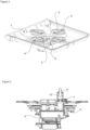
Figure 2 - is the perspective view of the spraying member and the stopping member. -
Figure 3 - is the cross-sectional view of the sump and the stopping member. -
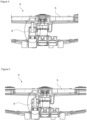
Figure 4 - is the cross-sectional view of the spraying member and the stopping member when the stopping member is in the open position. -
Figure 5 - is the cross-sectional view of the spraying member and the stopping member when the stopping member is in the closed position. -
Figure 6 - is the exploded view of the stopping member. - The elements illustrated in the figures are numbered as follows:
- 1- Dishwasher
- 2- Body
- 3- Washing tub
- 4- Sump
- 5- Spraying member
- 6- Multiport valve
- 7- Delivery line
- 8- Secondary spray arms
- 9- Stopping member
- 10- Housing
- 11- Piston
- 12- Hole
- 13-First surface
- 14- Second surface
- 15- Cut-out
- 16- Opening
- 17- Protrusion
- A- Open position
- K- Closed position
- The dishwasher (1) comprises a body (2); a washing tub (3) which is disposed in the body (2) and wherein the washing process is performed; a sump (4) which is disposed under the washing tub (3); at least one spraying member (5) which is disposed in the washing tub (3) and which delivers the water onto the kitchen items; a multiport valve (6) which delivers the water from the sump (4) to the spraying member (5); a delivery line (7) which is disposed between the multiport valve (6) and each spraying member (5); and at least one secondary spray arm (8) which rotates its own axis with the force of the water so as to enable the water to be delivered in various directions. The water collected in the sump (4) is delivered to the spraying members (5) by means of the multiport valve (6) and the connected delivery line (7). By means of the multiport valve (6), it is controlled which spraying member (5) receives the water. The multiport valve (6), which operates as a shutter system, enables the water to be delivered to areas such as the lower spraying member (5), the upper spraying member (5), the top washing or the intensive washing. The secondary spray arms (8) provided on the spraying member (5) can rotate around their own axes under the influence of water. By means of the rotation of the spraying member (5) around its own axis and the rotation of the secondary spray arms (8) around their own axes, the water is delivered in various configurations in the washing tub (3), providing homogeneous washing.
- The dishwasher (1) of the present invention comprises a stopping member (9) which is disposed on the delivery line (7) so as to be under the spraying member (5) and which has an open position where the stopping member (9) prevents the spraying member (5) from moving around its own axis by moving depending on the pressure of the water coming from the delivery line (7), and a closed position where the stopping member (9) does not come into contact with the spraying member (5). The stopping member (9) moves vertically upwards and shifts to the open position. When the stopping member (9) is in the open position, the rotation of the spraying member (5) around its own axis is stopped. Thus, only the secondary spray arms (8) rotate around their own axes under the effect of the incoming water. Various washing areas are established by means of the secondary spray arms (8) being able to rotate in a fixed area in the washing tub (3). Thus, the washing tub (3) is provided with various intensive washing areas.
- In an embodiment of the present invention, the dishwasher (1) comprises the stopping member (9) having a housing (10) which is attached onto the delivery line (7), a piston (11) which moves in the housing (10) and a hole (12) which is provided on the upper surface of the housing (10) and which enables the piston (11) to at least partially come out of the housing (10) when in the open position. The piston (11) moves vertically in the housing (10) under the influence of water. The piston (11) comes out of the hole (12) and comes into contact with the spraying member (5). Thus, the spraying member (5) is enabled to be stopped.
- In an embodiment of the present invention, the dishwasher (1) comprises the stopping member (9) having the piston (11) which moves in the vertical plane in the housing (10) with the pressure of water coming from the delivery line (7) by means of a first surface (13) provided on the piston (11) and a second surface (14) immediately following the same. The first surface (13) and the second surface (14) are positioned one after the other on the piston (11) at a certain interval. The piston (11) is enabled to move with the pressure of water by means of the surfaces (13 and 14). By means of the first surface (13) and the second surface (14), the pressure force of the water is efficiently converted into kinetic energy.
- In an embodiment of the present invention, the dishwasher (1) comprises a plurality of cut-outs (15) which are arranged all around the first surface (13) and the second surface (14) and which ensure the continuity of the water flow while the piston (11) moves in the housing (10). The cut-outs (15) are arranged around the first surface (13) and the second surface (14). Thus, the vacuum effect which may be generated due to the water pressure in the housing (10) during the movement of the piston (11) is prevented. The pressure of the water coming from the delivery line (7) is enabled to directly move the piston (11).
- In an embodiment of the present invention, the dishwasher (1) comprises a plurality of openings which are arranged almost peripherally on the housing (10). By means of the housing (10) having the peripherally-arranged openings (16) close to the bottom, the movement of the piston (11) is prevented from moving due to possible water leaks. Thus, the piston (11) is shifted between the open position and the closed position in a controlled manner.
- In an embodiment of the present invention, the dishwasher (1) comprises a protrusion (16) which is provided on the second surface (14) and which bears against the edge of the hole (12) when the stopping member (9) is in the open position so as to prevent the piston (11) from moving further. The peripheral protrusion (16) provided on the second surface (14) bears against the edge of the hole (12). Thus, the piston (11) is prevented from coming out of the housing (10) any further when the stopping member (9) is in the open position.
- In one embodiment of the invention, the dishwasher (1) comprises the stopping member (9) which, when in the open position, ensures that the water coming from the delivery line (7) pushes the first surface (13) such that the piston (11) moves upwards in the vertical plane and comes out of the hole (12) and stops the spraying member (5) and which, when in the closed position, ensures that the piston (11) remains completely in the housing (10) such that the movement of the spraying member (5) is not blocked. When the stopping member (9) is in the open position, the water coming from the delivery line (7) pushes the first surface (13) and the second surface (14) such that the piston (11) moves upwards in the vertical plane. Thus, the piston (11) contacts the spraying member (5) and prevents the same from rotating around its own axis, enabling only the secondary spray arms (8) to rotate. The rotating secondary spray arms (8) establish fixed intensive washing areas. When the stopping member (9) is in the closed position, the piston (11) remains in the housing (10) and the spraying member (5) rotates around its own axis. Thus, homogeneous washing is performed.
- By means of the present invention, a dishwasher (1) is realized, wherein the stopping of the spraying member (5) is controlled by means of a stopping member (9) which can shift between the open position and the closed position with the effect of water pressure. Intensive washing areas are established by means of the secondary spray arms (8) disposed on the stopped spraying member (5). When the spraying member (5) rotates around its own axis, homogeneous washing is provided.
Claims (7)
- A dishwasher (1) comprising a body (2); a washing tub (3) which is disposed in the body (2) and wherein the washing process is performed; a sump (4) which is disposed under the washing tub (3); at least one spraying member (5) which is disposed in the washing tub (3) and which delivers the water onto the kitchen items; a multiport valve (6) which delivers the water from the sump (4) to the spraying member (5); a delivery line (7) which is disposed between the multiport valve (6) and each spraying member (5); and at least one secondary spray arm (8) which rotates its own axis with the force of the water so as to enable the water to be delivered in various directions, characterized by a stopping member (9) which is disposed on the delivery line (7) so as to be under the spraying member (5) and which has an open position where the stopping member (9) prevents the spraying member (5) from moving around its own axis by moving depending on the pressure of the water coming from the delivery line (7), and a closed position where the stopping member (9) does not come into contact with the spraying member (5).
- A dishwasher (1) as in Claim 1, characterized by the stopping member (9) having a housing (10) which is attached onto the delivery line (7), a piston (11) which moves in the housing (10) and a hole (12) which is provided on the upper surface of the housing (10) and which enables the piston (11) to at least partially come out of the housing (10) when in the open position.
- A dishwasher (1) as in Claim 1 or Claim 2, characterized by the stopping member (9) having the piston (11) which moves in the housing (10) with the pressure of water coming from the delivery line (7) by means of a first surface (13) provided on the piston (11) and a second surface (14) immediately following the same.
- A dishwasher (1) as in Claim 3, characterized by a plurality of cut-outs (15) which are arranged all around the first surface (13) and the second surface (14) and which ensure the continuity of the water flow while the piston (11) moves in the housing (10).
- A dishwasher (1) as in any one of Claims 2 to 4, characterized by a plurality of openings (16) which are arranged almost peripherally on the housing (10).
- A dishwasher (1) as in any one of Claims 3 to 5, characterized by a protrusion (17) which is provided on the second surface (14) and which bears against the edge of the hole (12) when the stopping member (9) is in the open position so as to prevent the piston (11) from moving further.
- A dishwasher (1) as in any one of Claims 2 to 6, characterized by the stopping member (9) which, when in the open position, ensures that the water coming from the delivery line (7) pushes the first surface (13) such that the piston (11) moves upwards in the vertical plane and comes out of the hole (12) and stops the spraying member (5) and which, when in the closed position, ensures that the piston (11) remains completely in the housing (10) such that the movement of the spraying member (5) is not blocked.
Applications Claiming Priority (1)
| Application Number | Priority Date | Filing Date | Title |
|---|---|---|---|
| TR202319458 | 2023-12-29 |
Publications (1)
| Publication Number | Publication Date |
|---|---|
| EP4578364A1 true EP4578364A1 (en) | 2025-07-02 |
Family
ID=93651211
Family Applications (1)
| Application Number | Title | Priority Date | Filing Date |
|---|---|---|---|
| EP24215175.1A Withdrawn EP4578364A1 (en) | 2023-12-29 | 2024-11-25 | A dishwasher providing intensive washing |
Country Status (1)
| Country | Link |
|---|---|
| EP (1) | EP4578364A1 (en) |
Citations (5)
| Publication number | Priority date | Publication date | Assignee | Title |
|---|---|---|---|---|
| DE1291869B (en) * | 1967-08-29 | 1969-04-03 | Bosch Hausgeraete Gmbh | Spray device for a dishwasher |
| US20160296097A1 (en) * | 2013-12-20 | 2016-10-13 | Electrolux Appliances Aktiebolag | Arrangement for a dishwasher for creating a wash zone with selectable position |
| EP2893862B1 (en) * | 2014-01-13 | 2017-11-29 | Miele & Cie. KG | Dishwasher |
| DE102020123416A1 (en) * | 2019-09-19 | 2021-03-25 | Miele & Cie. Kg | Method for cleaning items to be washed in a dishwasher and dishwasher |
| WO2022258337A1 (en) | 2021-06-11 | 2022-12-15 | BSH Hausgeräte GmbH | Domestic dishwasher and method |
-
2024
- 2024-11-25 EP EP24215175.1A patent/EP4578364A1/en not_active Withdrawn
Patent Citations (5)
| Publication number | Priority date | Publication date | Assignee | Title |
|---|---|---|---|---|
| DE1291869B (en) * | 1967-08-29 | 1969-04-03 | Bosch Hausgeraete Gmbh | Spray device for a dishwasher |
| US20160296097A1 (en) * | 2013-12-20 | 2016-10-13 | Electrolux Appliances Aktiebolag | Arrangement for a dishwasher for creating a wash zone with selectable position |
| EP2893862B1 (en) * | 2014-01-13 | 2017-11-29 | Miele & Cie. KG | Dishwasher |
| DE102020123416A1 (en) * | 2019-09-19 | 2021-03-25 | Miele & Cie. Kg | Method for cleaning items to be washed in a dishwasher and dishwasher |
| WO2022258337A1 (en) | 2021-06-11 | 2022-12-15 | BSH Hausgeräte GmbH | Domestic dishwasher and method |
Similar Documents
| Publication | Publication Date | Title |
|---|---|---|
| CN112654279B (en) | Dishwasher with rotatable diverter valve | |
| US8905053B2 (en) | Variable speed and multi-angle nozzle spray arm assembly for a dishwasher | |
| WO2019061970A1 (en) | Dishwasher with discretely directable tubular spray elements | |
| EP3122228B1 (en) | Dishwasher comprising at least one dishwasher spray arm | |
| EP3834694B1 (en) | Dishwasher and method for operating same | |
| KR20160100954A (en) | Arrangement in a dishwasher for creating a wash zone with intensified washing | |
| EP3403564B1 (en) | Sprayer arrangement for a dishwasher | |
| RU2647139C2 (en) | Device in a dish-washing machine intended for creating a washing area with a selectable position | |
| CN112672669A (en) | Dishwasher with docking device for a lifting rack | |
| WO2015018671A1 (en) | A dishwasher with improved washing effectiveness | |
| US10945580B2 (en) | Spray nozzle for a dishwasher appliance | |
| US20110220149A1 (en) | Spray device for an appliance and method of operation | |
| US7426933B2 (en) | Dishwasher with kinetic energy water distribution system | |
| EP3222193A1 (en) | A distribution valve | |
| US12059113B2 (en) | Diverter assembly for dishwasher | |
| US10512387B2 (en) | Hydraulically actuated diverter for an appliance | |
| CN119451614A (en) | Dishwasher with improved spray device | |
| EP3791768B1 (en) | A dishwasher with improved washing effectiveness | |
| EP4578370A1 (en) | A dishwasher comprising movable wires | |
| CN224193443U (en) | Spraying devices and cleaning equipment | |
| US12622566B2 (en) | Non-radiating pump cover | |
| US12245735B2 (en) | Dishwasher including tubular spray element with intermediate support and/or fluid inlet | |
| CN113243868A (en) | Automatic dish-washing machine | |
| WO2024005766A1 (en) | A dishwasher comprising a customized spraying member | |
| CN117257196A (en) | Spraying device of dish washer, dish washer and control method of dish washer |
Legal Events
| Date | Code | Title | Description |
|---|---|---|---|
| PUAI | Public reference made under article 153(3) epc to a published international application that has entered the european phase |
Free format text: ORIGINAL CODE: 0009012 |
|
| STAA | Information on the status of an ep patent application or granted ep patent |
Free format text: STATUS: REQUEST FOR EXAMINATION WAS MADE |
|
| 17P | Request for examination filed |
Effective date: 20241125 |
|
| AK | Designated contracting states |
Kind code of ref document: A1 Designated state(s): AL AT BE BG CH CY CZ DE DK EE ES FI FR GB GR HR HU IE IS IT LI LT LU LV MC ME MK MT NL NO PL PT RO RS SE SI SK SM TR |
|
| STAA | Information on the status of an ep patent application or granted ep patent |
Free format text: STATUS: THE APPLICATION IS DEEMED TO BE WITHDRAWN |
|
| 18D | Application deemed to be withdrawn |
Effective date: 20260103 |