EP4578329A2 - Electronic device protective cover - Google Patents
Electronic device protective cover Download PDFInfo
- Publication number
- EP4578329A2 EP4578329A2 EP24210709.2A EP24210709A EP4578329A2 EP 4578329 A2 EP4578329 A2 EP 4578329A2 EP 24210709 A EP24210709 A EP 24210709A EP 4578329 A2 EP4578329 A2 EP 4578329A2
- Authority
- EP
- European Patent Office
- Prior art keywords
- protective
- electronic device
- corner
- hand strap
- protective shell
- Prior art date
- Legal status (The legal status is an assumption and is not a legal conclusion. Google has not performed a legal analysis and makes no representation as to the accuracy of the status listed.)
- Pending
Links
Images


Classifications
-
- A—HUMAN NECESSITIES
- A45—HAND OR TRAVELLING ARTICLES
- A45F—TRAVELLING OR CAMP EQUIPMENT: SACKS OR PACKS CARRIED ON THE BODY
- A45F5/00—Holders or carriers for hand articles; Holders or carriers for use while travelling or camping
- A45F5/1525—Holders or carriers for portable computing devices, e.g. laptops, tablets or calculators
-
- A—HUMAN NECESSITIES
- A45—HAND OR TRAVELLING ARTICLES
- A45C—PURSES; LUGGAGE; HAND CARRIED BAGS
- A45C11/00—Receptacles for purposes not provided for in groups A45C1/00-A45C9/00
-
- H—ELECTRICITY
- H05—ELECTRIC TECHNIQUES NOT OTHERWISE PROVIDED FOR
- H05K—PRINTED CIRCUITS; CASINGS OR CONSTRUCTIONAL DETAILS OF ELECTRIC APPARATUS; MANUFACTURE OF ASSEMBLAGES OF ELECTRICAL COMPONENTS
- H05K5/00—Casings, cabinets or drawers for electric apparatus
- H05K5/02—Details
- H05K5/0217—Mechanical details of casings
-
- A—HUMAN NECESSITIES
- A45—HAND OR TRAVELLING ARTICLES
- A45C—PURSES; LUGGAGE; HAND CARRIED BAGS
- A45C13/00—Details; Accessories
- A45C13/26—Special adaptations of handles
-
- H—ELECTRICITY
- H05—ELECTRIC TECHNIQUES NOT OTHERWISE PROVIDED FOR
- H05K—PRINTED CIRCUITS; CASINGS OR CONSTRUCTIONAL DETAILS OF ELECTRIC APPARATUS; MANUFACTURE OF ASSEMBLAGES OF ELECTRICAL COMPONENTS
- H05K5/00—Casings, cabinets or drawers for electric apparatus
- H05K5/0086—Casings, cabinets or drawers for electric apparatus portable, e.g. battery operated apparatus
-
- H—ELECTRICITY
- H05—ELECTRIC TECHNIQUES NOT OTHERWISE PROVIDED FOR
- H05K—PRINTED CIRCUITS; CASINGS OR CONSTRUCTIONAL DETAILS OF ELECTRIC APPARATUS; MANUFACTURE OF ASSEMBLAGES OF ELECTRICAL COMPONENTS
- H05K5/00—Casings, cabinets or drawers for electric apparatus
- H05K5/02—Details
- H05K5/0217—Mechanical details of casings
- H05K5/023—Handles; Grips
-
- A—HUMAN NECESSITIES
- A45—HAND OR TRAVELLING ARTICLES
- A45C—PURSES; LUGGAGE; HAND CARRIED BAGS
- A45C11/00—Receptacles for purposes not provided for in groups A45C1/00-A45C9/00
- A45C11/002—Receptacles for purposes not provided for in groups A45C1/00-A45C9/00 for storing portable handheld communication devices, e.g. pagers or smart phones
-
- A—HUMAN NECESSITIES
- A45—HAND OR TRAVELLING ARTICLES
- A45C—PURSES; LUGGAGE; HAND CARRIED BAGS
- A45C11/00—Receptacles for purposes not provided for in groups A45C1/00-A45C9/00
- A45C11/003—Receptacles for purposes not provided for in groups A45C1/00-A45C9/00 for storing portable computing devices, e.g. laptops, tablets or calculators
-
- A—HUMAN NECESSITIES
- A45—HAND OR TRAVELLING ARTICLES
- A45C—PURSES; LUGGAGE; HAND CARRIED BAGS
- A45C13/00—Details; Accessories
- A45C13/005—Hinges
-
- A—HUMAN NECESSITIES
- A45—HAND OR TRAVELLING ARTICLES
- A45C—PURSES; LUGGAGE; HAND CARRIED BAGS
- A45C2200/00—Details not otherwise provided for in A45C
- A45C2200/15—Articles convertible into a stand, e.g. for displaying purposes
-
- A—HUMAN NECESSITIES
- A45—HAND OR TRAVELLING ARTICLES
- A45F—TRAVELLING OR CAMP EQUIPMENT: SACKS OR PACKS CARRIED ON THE BODY
- A45F5/00—Holders or carriers for hand articles; Holders or carriers for use while travelling or camping
- A45F2005/008—Hand articles fastened to the wrist or to the arm or to the leg
Definitions
- the present disclosure generally relates to a protective cover. More particularly, the present disclosure relates to an electronic device protective cover.
- the portable electronic devices are gradually developing toward the improvement of operating performance, and also gradually developing toward the direction of slim appearance.
- the portable electronic device may be damaged if the portable electronic device is accidentally dropped.
- One objective of the embodiments of the present invention is to provide an electronic device protective cover to effectively protect an electronic device stored therein and further improve the safety and convenience while using the electronic devices.
- the embodiments of the present invention provides an electronic device protective cover to protect an electronic device.
- the electronic device protective cover includes a first protective shell, a second protective shell, a pivot and a rotatable hand strap module.
- the pivot is connected between the first protective shell and the second protective shell.
- the rotatable hand strap module is rotatably installed on the second protective shell.
- the first protective shell includes a first protective corner, a second protective corner and a connecting part.
- the connecting part is connected between the first protective corner and the second protective corner.
- the second protective shell includes a base plate, a third protective corner and a fourth protective corner.
- the third protective corner is disposed on the base plate and the fourth protective corner is disposed on the base plate.
- the first protective corner and the second protective corner are symmetrical to the third protective corner and the fourth protective corner.
- the rotatable hand strap module further includes a fixed shaft penetrating through the rotating plate and the second protective shell so that the rotatable hand strap module is rotatably installed on the second protective shell.
- the hand strap includes a first U-shaped part, a second U-shaped part connected to the first U-shaped part and a third U-shaped part connected to the second U-shaped part.
- the second U-shaped part of the hand strap is fixed on the rotating plate.
- the first protective shell includes a first protective corner, a second protective corner and a connecting part.
- the connecting part is connected between the first protective corner and the second protective corner, and the first protective corner is fixed on a first corner of the electronic device and the second protective corner is fixed on a second corner of the electronic device.
- the second protective shell includes a base plate, a third protective corner and a fourth protective corner.
- the third protective corner is disposed on the base plate and the fourth protective corner is disposed on the base plate.
- the third protective corner is fixed on a third corner of the electronic device and the fourth protective corner is fixed on a fourth corner of the electronic device, and the first protective corner and the second protective corner are symmetrical to the third protective corner and the fourth protective corner.
- the electronic device protective cover further includes a plurality of fixing devices penetrating through the first protective corner, the second protective corner, the third protective corner and the fourth protective corner to fix the first protective corner on the first corner of the electronic device, the second protective corner on the second corner of the electronic device, the third protective corner on the third corner of the electronic device, and the fourth protective corner on the fourth corner of the electronic device.
- the second protective shell is able to rotate along the pivot to allow the electronic device to stand on a surface when some of the fixing devices are released to separate the third protective corner from the third corner of the electronic device and the fourth protective corner from the fourth corner of the electronic device.
- the electronic device protective cover disclosed in the present invention may effectively protect the electronic device stored therein, and is convenient to carry and convenient for users to watch videos so as to be conveniently used in various environments and effectively improve the safety and convenience of the electronic device while using the electronic device.
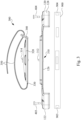
- Fig. 1 illustrates a schematic perspective view showing an electronic device protective cover and an electronic device according to one embodiment of the present invention
- Fig. 2 is a schematic exploded view thereof
- Fig. 3 is a schematic exploded view showing an electronic device protective cover and an electronic device according to another embodiment of the present invention.
- the electronic device protective cover 100 is utilized to protect an electronic device 900, such as a tablet computer, a mobile phone or any other electronic device.
- the electronic device protective cover 100 includes a first protective shell 110, a second protective shell 120, a pivot 130 and a rotatable hand strap module 200.
- the pivot 130 is connected between the first protective shell 110 and the second protective shell 120 to allow the second protective shell 120 able to rotate relative to the first protective shell 110.
- the rotatable hand strap module 200 is rotatably installed on the second protective shell 120. Therefore, the rotatable hand strap module 200 may not only rotate relative to the second protective shell 120 but also rotate relative to the first protective shell 110.
- the first protective shell 110 and the second protective shell 120 of the electronic device protective cover 100 surround the electronic device 900 so as to effectively protect the electronic device 900.
- the electronic device fixed thereon may be rotated in at least two rotation directions relative to the hand of the user, and preferably the two rotation directions are perpendicular to each other, but not limited to this.
- the fixed shaft 210 includes an external thread bolt 214 and an internal thread sleeve nut 212.
- the internal thread sleeve nut 212 penetrates through the rotating plate 220 and the second protective shell 120, and the external thread bolt 214 is fixed to the internal thread sleeve nut 212 so that the rotatable hand strap module 200 is rotatably installed on the second protective shell 120.
Landscapes
- Engineering & Computer Science (AREA)
- Microelectronics & Electronic Packaging (AREA)
- Casings For Electric Apparatus (AREA)
- Telephone Set Structure (AREA)
Abstract
Description
- The present disclosure generally relates to a protective cover. More particularly, the present disclosure relates to an electronic device protective cover.
- With the advancement of technology, the electronic products have become more popular, and gradually changed the life or work of many people. Besides good operation functions, the electronic products must also have portability as an important factor for users to consider purchasing.
- The portable electronic devices are gradually developing toward the improvement of operating performance, and also gradually developing toward the direction of slim appearance. When the portable electronic device is being used or carried, the portable electronic device may be damaged if the portable electronic device is accidentally dropped.
- In addition, when using a portable electronic device, a simple and smooth casing of the electronic device is not suitable for operation, and also inconvenient to watch movies or hand carry.
- Hence, there is a need to provide an electronic device protective cover able to effectively protect an electronic device stored therein, easily carry the electronic device, and conveniently watch videos on the electronic device so as to improve the safety and convenience of the electronic device while using the electronic device.
- One objective of the embodiments of the present invention is to provide an electronic device protective cover to effectively protect an electronic device stored therein and further improve the safety and convenience while using the electronic devices.
- To achieve these and other advantages and in accordance with the objective of the embodiments of the present invention, as the embodiment broadly describes herein, the embodiments of the present invention provides an electronic device protective cover to protect an electronic device. The electronic device protective cover includes a first protective shell, a second protective shell, a pivot and a rotatable hand strap module. The pivot is connected between the first protective shell and the second protective shell. The rotatable hand strap module is rotatably installed on the second protective shell.
- In some embodiments, the first protective shell includes a first protective corner, a second protective corner and a connecting part. The connecting part is connected between the first protective corner and the second protective corner.
- In some embodiments, the second protective shell includes a base plate, a third protective corner and a fourth protective corner. The third protective corner is disposed on the base plate and the fourth protective corner is disposed on the base plate. In addition, the first protective corner and the second protective corner are symmetrical to the third protective corner and the fourth protective corner.
- In some embodiments, the second protective shell is rotatable a predetermined angle along the pivot.
- In some embodiments, the rotatable hand strap module includes a rotating plate and a hand strap. The rotating plate is rotatably installed on the second protective shell. The hand strap penetrates through the rotating plate.
- In some embodiments, the rotatable hand strap module further includes a fixed shaft penetrating through the rotating plate and the second protective shell so that the rotatable hand strap module is rotatably installed on the second protective shell.
- In some embodiments, the fixed shaft includes an internal thread sleeve nut and an external thread bolt. The internal thread sleeve nut penetrates through the rotating plate and the second protective shell and the external thread bolt is fixed to the internal thread sleeve nut so that the rotatable hand strap module is rotatably installed on the second protective shell.
- In some embodiments, the hand strap includes a first U-shaped part, a second U-shaped part connected to the first U-shaped part and a third U-shaped part connected to the second U-shaped part.
- In some embodiments, the rotatable hand strap module further includes a fixing ring, and the first U-shaped part of the hand strap is fixed on the fixing ring.
- In some embodiments, the second U-shaped part of the hand strap is fixed on the rotating plate.
- In some embodiments, the third U-shaped part of the hand strap passes through the fixing ring to adjust a tightness of the hand strap.
- In some embodiments, the rotatable hand strap module further includes a bonding device fixed on the third U-shaped part of the hand strap to adjust the tightness of the hand strap according to a requirement.
- In some embodiments, the rotating plate of the rotatable hand strap module is connected to the hand strap, and the rotating plate and the hand strap are formed in one piece using double injection molding.
- In some embodiments, the rotatable hand strap module further includes a fixing ring connected to the rotating plate. The fixing ring, the rotating plate and the hand strap are formed in one piece using double injection molding.
- In some embodiments, the rotatable hand strap module further includes a bonding device formed on the hand strap to adjust a tightness of the hand strap according to a requirement.
- According to another aspect of the present invention, an electronic device protective cover to protect an electronic device is provided. The electronic device protective cover includes a first protective shell, a second protective shell, a pivot and a rotatable hand strap module. The pivot is connected between the first protective shell and the second protective shell, and the first protective shell and the second protective shell surround the electronic device. In addition, the rotatable hand strap module is rotatably installed on the second protective shell.
- In some embodiments, the first protective shell includes a first protective corner, a second protective corner and a connecting part. The connecting part is connected between the first protective corner and the second protective corner, and the first protective corner is fixed on a first corner of the electronic device and the second protective corner is fixed on a second corner of the electronic device.
- In some embodiments, the second protective shell includes a base plate, a third protective corner and a fourth protective corner. The third protective corner is disposed on the base plate and the fourth protective corner is disposed on the base plate. In addition, the third protective corner is fixed on a third corner of the electronic device and the fourth protective corner is fixed on a fourth corner of the electronic device, and the first protective corner and the second protective corner are symmetrical to the third protective corner and the fourth protective corner.
- In some embodiments, the electronic device protective cover further includes a plurality of fixing devices penetrating through the first protective corner, the second protective corner, the third protective corner and the fourth protective corner to fix the first protective corner on the first corner of the electronic device, the second protective corner on the second corner of the electronic device, the third protective corner on the third corner of the electronic device, and the fourth protective corner on the fourth corner of the electronic device.
- In some embodiments, the second protective shell is able to rotate along the pivot to allow the electronic device to stand on a surface when some of the fixing devices are released to separate the third protective corner from the third corner of the electronic device and the fourth protective corner from the fourth corner of the electronic device.
- Hence, the electronic device protective cover disclosed in the present invention may effectively protect the electronic device stored therein, and is convenient to carry and convenient for users to watch videos so as to be conveniently used in various environments and effectively improve the safety and convenience of the electronic device while using the electronic device.
- The foregoing aspects and many of the attendant advantages of this invention will be more readily appreciated as the same becomes better understood by reference to the following detailed description, when taken in conjunction with the accompanying drawings, wherein:
-
Fig. 1 illustrates a schematic perspective view showing an electronic device protective cover and an electronic device according to one embodiment of the present invention; -
Fig. 2 is a schematic exploded view showing an electronic device protective cover and an electronic device according to one embodiment of the present invention; and -
Fig. 3 is a schematic exploded view showing an electronic device protective cover and an electronic device according to another embodiment of the present invention. - The following is a detailed description of the embodiments in conjunction with the accompanying drawings.
-
Fig. 1 illustrates a schematic perspective view showing an electronic device protective cover and an electronic device according to one embodiment of the present invention, andFig. 2 is a schematic exploded view thereof. In addition,Fig. 3 is a schematic exploded view showing an electronic device protective cover and an electronic device according to another embodiment of the present invention. - Referring to
Fig. 1 andFig. 2 , the electronic deviceprotective cover 100 is utilized to protect anelectronic device 900, such as a tablet computer, a mobile phone or any other electronic device. - The electronic device
protective cover 100 includes a firstprotective shell 110, a secondprotective shell 120, apivot 130 and a rotatablehand strap module 200. Thepivot 130 is connected between the firstprotective shell 110 and the secondprotective shell 120 to allow the secondprotective shell 120 able to rotate relative to the firstprotective shell 110. The rotatablehand strap module 200 is rotatably installed on the secondprotective shell 120. Therefore, the rotatablehand strap module 200 may not only rotate relative to the secondprotective shell 120 but also rotate relative to the firstprotective shell 110. - In some embodiments, the first
protective shell 110 and the secondprotective shell 120 of the electronic deviceprotective cover 100 surround theelectronic device 900 so as to effectively protect theelectronic device 900. - Therefore, when a user holds the electronic device through the rotatable
hand strap module 200, the electronic device fixed thereon may be rotated in at least two rotation directions relative to the hand of the user, and preferably the two rotation directions are perpendicular to each other, but not limited to this. - In some embodiments, the first
protective shell 110 includes a firstprotective corner 112, a secondprotective corner 114 and a connectingpart 116. The connectingpart 116 is connected between the firstprotective corner 112 and the secondprotective corner 114. The firstprotective corner 112 is preferably fixed on thefirst corner 901 of theelectronic device 900, and the secondprotective corner 114 is preferably fixed on thesecond corner 902 of theelectronic device 900. - In some embodiments, the second
protective shell 120 includes abase plate 126, a thirdprotective corner 122 and a fourthprotective corner 124. The thirdprotective corner 122 and the fourthprotective corner 124 are disposed on thebase plate 126. In addition, the firstprotective corner 112 and the secondprotective corner 114 are preferably disposed symmetrically with the thirdprotective corner 122 and the fourthprotective corner 124. - In some embodiments, the third
protective corner 122 is preferably fixed on thethird corner 903 of theelectronic device 900, and the fourthprotective corner 124 is preferably fixed on thefourth corner 904 of theelectronic device 900 to effectively utilize the firstprotective corner 112, the secondprotective corner 114, the thirdprotective corner 122 and the fourthprotective corner 124 to protect thefirst corner 901, thesecond corner 902, thethird corner 903 and thefourth corner 904 of theelectronic device 900. Therefore, the four corners of theelectronic device 900 may be safely protected by the electronic deviceprotective cover 100, thereby improving the impact resistance of theelectronic device 900. - In addition, it is worth noting that the second
protective shell 120 may rotate along thepivot 130 at a predetermined angle, for example, greater than 5 degrees and less than 175 degrees, and preferably between 30 degrees and 120 degrees. Therefore, the secondprotective shell 120 may be transformed into a supporting stand for theelectronic device 900 to support theelectronic device 900 on a plane surface so as to form a display mode. Accordingly, the user may conveniently watch the pictures on the display of theelectronic device 900. - In some embodiments, the electronic device
protective cover 100 further includes a plurality of fixingdevices 400, i.e. afirst fixator 401, asecond fixator 402, athird fixator 403 and afourth fixator 404 such as bolts, rivets, magnetic buckles or any fixing device. Thefirst fixator 401, thesecond fixator 402, thethird fixator 403 and thefourth fixator 404 of the fixingdevices 400 respectively penetrate through the firstprotective corner 112, the secondprotective corner 114, the thirdprotective corner 122 and the fourthprotective corner 124 to fix the firstprotective corner 112 on thefirst corner 901 of theelectronic device 900, the secondprotective corner 114 on thesecond corner 902 of theelectronic device 900, the thirdprotective corner 122 on thethird corner 903 of theelectronic device 900, and the fourthprotective corner 124 on thefourth corner 904 of theelectronic device 900. - In some embodiments, when some of the fixing
devices 400, for example, thethird fixator 403 and thefourth fixator 404 such as quick release screws or magnetic fixing devices are released, the thirdprotective corner 122 may be separated from thethird corner 903 of theelectronic device 900 and the fourthprotective corner 124 may be separated from thefourth corner 904 of theelectronic device 900 to allow the secondprotective shell 120 to rotate along thepivot 130 so as to allow theelectronic device 900 to stand on a plane surface such as a desktop and so on. - Further referring to
Fig. 2 , the rotatablehand strap module 200 includes arotating plate 220, a fixedshaft 210 and ahand strap 230. Therotating plate 220 may be rotatably installed on the secondprotective shell 120, and thehand strap 230 may penetrate throughrotating plate 220. The fixedshaft 210 penetrates through therotating plate 220 and the secondprotective shell 120 to allow the rotatablehand strap module 200 rotatably installed on the secondprotective shell 120. - In some embodiments, the fixed
shaft 210 includes anexternal thread bolt 214 and an internalthread sleeve nut 212. The internalthread sleeve nut 212 penetrates through therotating plate 220 and the secondprotective shell 120, and theexternal thread bolt 214 is fixed to the internalthread sleeve nut 212 so that the rotatablehand strap module 200 is rotatably installed on the secondprotective shell 120. - In some embodiments, the
hand strap 230 includes a firstU-shaped part 232, a secondU-shaped part 234 and a thirdU-shaped part 236. The firstU-shaped part 232, the secondU-shaped part 234 and the thirdU-shaped part 236 are sequentially connected. In addition, the rotatablehand strap module 200 further includes a fixingring 240, and the firstU-shaped part 232 of thehand strap 230 is fixed on the fixingring 240. Furthermore, the secondU-shaped part 234 of thehand strap 230 is fixed on therotating plate 220. The thirdU-shaped part 236 of thehand strap 230 may pass through the fixingring 240 to adjust the tightness of thehand strap 230. - In some embodiments, the rotatable
hand strap module 200 further includes abonding device 250 fixed on the thirdU-shaped part 236 of thehand strap 230 to adjust the tightness of thehand strap 230 according to the requirement. In addition, thebonding device 250 may be a hook and loop fastener, a belt buckle, button or magnetic buckle. - Further referring to
Fig. 3 , as shown in the drawing, the electronic deviceprotective cover 100 may be equipped with a rotatablehand strap module 300, and the rotatablehand strap module 300 is fixed on the secondprotective shell 120 through the fixedshaft 310. - The fixed
shaft 310 includes anexternal thread bolt 314 and an internalthread sleeve nut 312. The internalthread sleeve nut 312 penetrates through therotating plate 320 and the secondprotective shell 120. Theexternal thread bolt 314 is fixed to the internalthread sleeve nut 312 so that the rotatablehand strap module 300 is rotatably installed on the secondprotective shell 120. - In some embodiments, the
rotating plate 320 of the rotatablehand strap module 300 is connected to thehand strap 330, and therotating plate 320 and thehand strap 330 are formed in one piece using double injection molding. - In some embodiments, the rotatable
hand strap module 300 may further include a fixingring 340, the fixingring 340 is connected to therotating plate 320. The fixingring 340, rotatingplate 320 and thehand strap 330 are formed in one piece using double injection molding so as to conveniently manufacture the rotatablehand strap module 300. In addition, the rotatablehand strap module 300 is formed in one piece using double injection molding so as to prevent the rotatablehand strap module 300 from being affected by moisture, and facilitate the user to use theelectronic device 900 in various environments. - In the same manner, the rotatable
hand strap module 300 may further include abonding device 350 formed on thehand strap 330 to conveniently adjust the tightness of thehand strap 330 according to the requirement of the user. In some embodiments, thebonding device 350 may be a hook and loop fastener, a belt buckle, button or magnetic buckle. - Accordingly, the electronic device protective cover disclosed in the present invention may effectively protect the electronic device stored therein, and is convenient to carry and convenient for users to watch videos so as to be conveniently used in various environments and effectively improve the safety and convenience while using the electronic devices.
Claims (15)
- An electronic device protective cover (100), characterized by comprising:a first protective shell (110);a second protective shell (120);a pivot (130) connected between the first protective shell (110) and the second protective shell (120); anda rotatable hand strap module (200, 300) rotatably installed on the second protective shell (120).
- The electronic device protective cover (100) of claim 1, wherein the first protective shell (110) comprises:a first protective corner (112);a second protective corner (114); anda connecting part (116) connected between the first protective corner (112) and the second protective corner (114).
- The electronic device protective cover (100) of claim 2, wherein the second protective shell (120) comprises:a base plate (126);a third protective corner (122) disposed on the base plate (126); anda fourth protective corner (124) disposed on the base plate (126), wherein the first protective corner (112) and the second protective corner (114) are symmetrical to the third protective corner (122) and the fourth protective corner (124).
- The electronic device protective cover (100) of any one of claims 1 to 3, wherein the second protective shell (120) is rotatable by a predetermined angle along the pivot (130).
- The electronic device protective cover (100) of claim 1, wherein the rotatable hand strap module (200, 300) comprises:a rotating plate (220, 320) rotatably installed on the second protective shell (120); anda hand strap (230, 330) penetrating through the rotating plate (220, 320).
- The electronic device protective cover (100) of claim 5, wherein the rotatable hand strap module (200, 300) further comprises:
a fixed shaft (210, 310) penetrating through the rotating plate (220, 320) and the second protective shell (120) to allow the rotatable hand strap module (200, 300) to rotatably install on the second protective shell (120). - The electronic device protective cover (100) of claim 6, wherein the fixed shaft (210, 310) comprises:an internal thread sleeve nut (212, 312) penetrating through the rotating plate (220, 320) and the second protective shell (120); andan external thread bolt (214, 314) fixed to the internal thread sleeve nut (212, 312) so that the rotatable hand strap module (200, 300) is rotatably installed on the second protective shell (120).
- The electronic device protective cover (100) of claim 5, wherein the hand strap (230) comprises a first U-shaped part (232), a second U-shaped part (234) connected to the first U-shaped part (232) and a third U-shaped part (236) connected to the second U-shaped part (234), wherein the second U-shaped part (234) of the hand strap (230) is fixed on the rotating plate (220).
- The electronic device protective cover (100) of claim 8, wherein the rotatable hand strap module (200) further comprises:
a fixing ring (240), wherein the first U-shaped part (232) of the hand strap (230) is fixed on the fixing ring (240), and the third U-shaped part (236) of the hand strap (230) passes through the fixing ring (240) to adjust a tightness of the hand strap (230). - The electronic device protective cover (100) of claim 5, wherein the rotating plate (320) of the rotatable hand strap module (300) is connected to the hand strap (330), and the rotating plate (320) and the hand strap (330) are formed in one piece using double injection molding.
- The electronic device protective cover (100) of claim 10, wherein the rotatable hand strap module (300) further comprises a fixing ring (340) connected to the rotating plate (320), and the fixing ring (340), the rotating plate (320) and the hand strap (330) are formed in one piece using the double injection molding.
- The electronic device protective cover (100) of any one of the claims 8 to 11, wherein the rotatable hand strap module (200, 300) further comprises a bonding device (250, 350) formed on the hand strap (230, 330) to adjust a tightness of the hand strap (230, 330) according to a requirement.
- The electronic device protective cover (100) as claimed in any one of the preceding claims, wherein the electronic device protective cover (100) is configured to protect an electronic device (900), characterized by:
wherein the first protective shell (110) and the second protective shell (120) surround the electronic device (900). - The electronic device protective cover (100) of claim 13, further comprising a plurality of fixing devices (400) penetrating through the first protective corner (112), the second protective corner (114), the third protective corner (122) and the fourth protective corner (124) to fix the first protective corner (112) on a first corner (901) of the electronic device (900), the second protective corner (114) on a second corner (902) of the electronic device (900), the third protective corner (122) on a third corner (903) of the electronic device (900), and the fourth protective corner (124) on a fourth corner (904) of the electronic device (900).
- The electronic device protective cover (100) of claim 14, wherein the second protective shell (120) is configured to rotate along the pivot (130) to allow the electronic device (900) to stand on a surface when some of the fixing devices (400) are released to separate the third protective corner (122) from the third corner (903) of the electronic device (900) and the fourth protective corner (124) from the fourth corner (904) of the electronic device (900).
Applications Claiming Priority (1)
| Application Number | Priority Date | Filing Date | Title |
|---|---|---|---|
| CN202311798610.6A CN120224596A (en) | 2023-12-25 | 2023-12-25 | Electronic device protection cover |
Publications (2)
| Publication Number | Publication Date |
|---|---|
| EP4578329A2 true EP4578329A2 (en) | 2025-07-02 |
| EP4578329A3 EP4578329A3 (en) | 2025-07-16 |
Family
ID=93430545
Family Applications (1)
| Application Number | Title | Priority Date | Filing Date |
|---|---|---|---|
| EP24210709.2A Pending EP4578329A3 (en) | 2023-12-25 | 2024-11-05 | Electronic device protective cover |
Country Status (3)
| Country | Link |
|---|---|
| US (1) | US20250204659A1 (en) |
| EP (1) | EP4578329A3 (en) |
| CN (1) | CN120224596A (en) |
Family Cites Families (7)
| Publication number | Priority date | Publication date | Assignee | Title |
|---|---|---|---|---|
| US5244134A (en) * | 1992-03-30 | 1993-09-14 | Timex Corporation | Strap attachment for a wrist instrument |
| US9204710B1 (en) * | 2010-05-12 | 2015-12-08 | Hand E Holder Products, Inc. | Rotational supporting device and system |
| US20120103855A1 (en) * | 2010-06-07 | 2012-05-03 | 360 Mobility Solutions, Llc | Cases for electronic devices |
| TWM418323U (en) * | 2011-07-22 | 2011-12-11 | Fu-Yi Hsu | Protective sheath |
| CN103121551A (en) * | 2011-11-18 | 2013-05-29 | 深圳富泰宏精密工业有限公司 | Multifunctional protective shell |
| US11907021B2 (en) * | 2019-02-01 | 2024-02-20 | Urban Armor Gear, Llc | Deployable case for electronic device and method of deploying a deployable case |
| US20210227960A1 (en) * | 2020-01-24 | 2021-07-29 | National Products, Inc. | Combination strap with magnets and stand support for tablets and hand held electronic devices |
-
2023
- 2023-12-25 CN CN202311798610.6A patent/CN120224596A/en active Pending
-
2024
- 2024-07-08 US US18/765,411 patent/US20250204659A1/en active Pending
- 2024-11-05 EP EP24210709.2A patent/EP4578329A3/en active Pending
Also Published As
| Publication number | Publication date |
|---|---|
| CN120224596A (en) | 2025-06-27 |
| US20250204659A1 (en) | 2025-06-26 |
| EP4578329A3 (en) | 2025-07-16 |
Similar Documents
| Publication | Publication Date | Title |
|---|---|---|
| US20110259771A1 (en) | Case for portable electronic device | |
| US8282060B2 (en) | Auxiliary fastening apparatus | |
| US9847805B2 (en) | Cradle-case combination with magnetic fastener feature | |
| US8794436B2 (en) | Protective sheath | |
| TWM415545U (en) | Hand-held buckling Plate computer screen Cover Pivot cap of | |
| US8979040B2 (en) | Supporting device | |
| US20120075789A1 (en) | Swiveling base for a portable computing device | |
| US20050002156A1 (en) | Display device and stand thereof | |
| US9062811B2 (en) | Support structure and electronic device using same | |
| US8219159B2 (en) | Cover flip mechanism and electronic device using the same | |
| US20060113338A1 (en) | Key palette improvements | |
| US11766122B1 (en) | Mount for clamping on a display | |
| US7349206B2 (en) | Notebook computer expansion module | |
| US20230130700A1 (en) | Case for a portable electronic device | |
| US20250204659A1 (en) | Electronic device protective cover | |
| US20120305739A1 (en) | Electronic device holder | |
| CN216416304U (en) | Electronic equipment protective sleeve and electronic equipment assembly | |
| TWI899767B (en) | Electronic device protective cover | |
| JP2003168876A (en) | Electronics | |
| KR102455737B1 (en) | Supporting structure for holding electronic device | |
| KR20110011394U (en) | Cradle for portable terminal | |
| CN213957944U (en) | A protective cover for a tablet computer | |
| JP2021048922A (en) | Holding tool | |
| CN222366304U (en) | Terminal protective shell | |
| CN217723147U (en) | Display device of intelligent watch |
Legal Events
| Date | Code | Title | Description |
|---|---|---|---|
| PUAI | Public reference made under article 153(3) epc to a published international application that has entered the european phase |
Free format text: ORIGINAL CODE: 0009012 |
|
| STAA | Information on the status of an ep patent application or granted ep patent |
Free format text: STATUS: THE APPLICATION HAS BEEN PUBLISHED |
|
| PUAL | Search report despatched |
Free format text: ORIGINAL CODE: 0009013 |
|
| AK | Designated contracting states |
Kind code of ref document: A2 Designated state(s): AL AT BE BG CH CY CZ DE DK EE ES FI FR GB GR HR HU IE IS IT LI LT LU LV MC ME MK MT NL NO PL PT RO RS SE SI SK SM TR |
|
| AK | Designated contracting states |
Kind code of ref document: A3 Designated state(s): AL AT BE BG CH CY CZ DE DK EE ES FI FR GB GR HR HU IE IS IT LI LT LU LV MC ME MK MT NL NO PL PT RO RS SE SI SK SM TR |
|
| RIC1 | Information provided on ipc code assigned before grant |
Ipc: A45C 11/00 20060101AFI20250612BHEP Ipc: A45F 5/00 20060101ALI20250612BHEP Ipc: G06F 1/00 20060101ALI20250612BHEP Ipc: A45C 13/26 20060101ALI20250612BHEP |
|
| STAA | Information on the status of an ep patent application or granted ep patent |
Free format text: STATUS: REQUEST FOR EXAMINATION WAS MADE |
|
| 17P | Request for examination filed |
Effective date: 20251222 |