EP4578320A2 - Shoe - Google Patents
Shoe Download PDFInfo
- Publication number
- EP4578320A2 EP4578320A2 EP25176957.6A EP25176957A EP4578320A2 EP 4578320 A2 EP4578320 A2 EP 4578320A2 EP 25176957 A EP25176957 A EP 25176957A EP 4578320 A2 EP4578320 A2 EP 4578320A2
- Authority
- EP
- European Patent Office
- Prior art keywords
- shoe
- stretch region
- shoe tongue
- shape
- medial side
- Prior art date
- Legal status (The legal status is an assumption and is not a legal conclusion. Google has not performed a legal analysis and makes no representation as to the accuracy of the status listed.)
- Pending
Links
Images






Classifications
-
- A—HUMAN NECESSITIES
- A43—FOOTWEAR
- A43B—CHARACTERISTIC FEATURES OF FOOTWEAR; PARTS OF FOOTWEAR
- A43B23/00—Uppers; Boot legs; Stiffeners; Other single parts of footwear
- A43B23/26—Tongues for shoes
-
- A—HUMAN NECESSITIES
- A43—FOOTWEAR
- A43B—CHARACTERISTIC FEATURES OF FOOTWEAR; PARTS OF FOOTWEAR
- A43B1/00—Footwear characterised by the material
- A43B1/02—Footwear characterised by the material made of fibres or fabrics made therefrom
- A43B1/04—Footwear characterised by the material made of fibres or fabrics made therefrom braided, knotted, knitted or crocheted
-
- A—HUMAN NECESSITIES
- A43—FOOTWEAR
- A43B—CHARACTERISTIC FEATURES OF FOOTWEAR; PARTS OF FOOTWEAR
- A43B3/00—Footwear characterised by the shape or the use
- A43B3/0036—Footwear characterised by the shape or the use characterised by a special shape or design
- A43B3/0063—U-shaped
-
- A—HUMAN NECESSITIES
- A43—FOOTWEAR
- A43B—CHARACTERISTIC FEATURES OF FOOTWEAR; PARTS OF FOOTWEAR
- A43B3/00—Footwear characterised by the shape or the use
- A43B3/0036—Footwear characterised by the shape or the use characterised by a special shape or design
- A43B3/0068—V-shaped
-
- D—TEXTILES; PAPER
- D04—BRAIDING; LACE-MAKING; KNITTING; TRIMMINGS; NON-WOVEN FABRICS
- D04B—KNITTING
- D04B1/00—Weft knitting processes for the production of fabrics or articles not dependent on the use of particular machines; Fabrics or articles defined by such processes
- D04B1/10—Patterned fabrics or articles
- D04B1/12—Patterned fabrics or articles characterised by thread material
-
- D—TEXTILES; PAPER
- D10—INDEXING SCHEME ASSOCIATED WITH SUBLASSES OF SECTION D, RELATING TO TEXTILES
- D10B—INDEXING SCHEME ASSOCIATED WITH SUBLASSES OF SECTION D, RELATING TO TEXTILES
- D10B2401/00—Physical properties
- D10B2401/06—Load-responsive characteristics
- D10B2401/061—Load-responsive characteristics elastic
-
- D—TEXTILES; PAPER
- D10—INDEXING SCHEME ASSOCIATED WITH SUBLASSES OF SECTION D, RELATING TO TEXTILES
- D10B—INDEXING SCHEME ASSOCIATED WITH SUBLASSES OF SECTION D, RELATING TO TEXTILES
- D10B2403/00—Details of fabric structure established in the fabric forming process
- D10B2403/02—Cross-sectional features
-
- D—TEXTILES; PAPER
- D10—INDEXING SCHEME ASSOCIATED WITH SUBLASSES OF SECTION D, RELATING TO TEXTILES
- D10B—INDEXING SCHEME ASSOCIATED WITH SUBLASSES OF SECTION D, RELATING TO TEXTILES
- D10B2501/00—Wearing apparel
- D10B2501/04—Outerwear; Protective garments
- D10B2501/043—Footwear
Definitions
- the present disclosure relates to a shoe.
- the purposes of providing a shoe tongue in a shoe are mainly to cover the wearer's instep portion to prevent soil and dust from entering inside the shoe and also to protect the instep portion from tightening pressure from a shoelace (see Patent Literatures 1 and 2, for example).
- the shoe tongue may be drawn into the shoe due to friction with the instep when the foot is inserted, or the wearer's foot may feel tight when it is inserted.
- the present disclosure has been made in view of such a problem, and a purpose thereof is to provide a shoe that achieves both the ease of foot insertion and the fit to a foot shape.
- a shoe according to one aspect of the present disclosure includes a sole, an upper joined to the sole, and a shoe tongue provided in a space formed by the sole and the upper.
- the shoe tongue is formed of a knitted member and includes a ridge portion of inverted V shape along the front and rear directions of the shoe.
- the shoe tongue may be formed of a single knitted member of sheet shape of which side ends on the medial side and the lateral side are each joined to the vicinity of a tangent between a bottom part and a side part in the space.
- the "being joined” may be, for example, being connected by means of sewing, bonding, vapor deposition, or the like. According to this aspect, since the both side ends of the shoe tongue are each joined to the vicinity of a tangent between the bottom part and a side part in the space, the shoe tongue can be made to fit the instep more easily such as to wrap around the entire midfoot portion.
- part of an area from the ridge portion to the side end on the medial side or the lateral side may be formed to have higher stretchability than at least part of other adjacent areas. According to this aspect, by providing highly stretchable regions from the ridge to the foot width directions, the shoe tongue can be made to fit to the foot width of each wearer more easily.
- the tip part may be formed thicker than at least part of other adjacent portions. According to this aspect, the smoothness for a foot of the shoe tongue can be made favorable, and the feeling of tightness at the ankle can be reduced.
- a thick portion of the tip part may be formed in a crescent shape in plan view, and each of the both ends of the crescent shape may extend toward the toe.
- Each of the both ends of the tip part may be located at a position overlapping and hidden by the upper and also overlapping an eyelet positioned closer to the ankle when the shoelace is tightened and tied, i.e., positioned at the uppermost end.
- the eyelet especially the metal eyelet
- the eyelet positioned at the uppermost end, with which the wearer often feels tightening of the shoelace, is less likely to come into direct contact with the instep, so that improved wearing comfort provided by protecting the instep can be expected.
- FIG. 1 is a schematic top view of a shoe according to the first embodiment.
- a configuration of a shoe 10 according to the present embodiment will be described with reference to the drawings.
- Each drawing mentioned below, including FIG. 1 illustrates a shoe and components thereof for a left foot, unless otherwise specified. However, the description in the present specification is also similarly applicable to a shoe and components thereof for a right foot.
- the shoe 10 of the present embodiment is a laced shoe used for sports such as running or walking.
- the shoe 10 includes an upper 20, a shoelace 30, a shoe tongue 50, and a sole 60.
- the right side of a center line C with respect to a foot width direction of the shoe 10 in FIG. 1 is referred to as a "medial side”
- the left side of the center line C in FIG. 1 is referred to as a "lateral side”.
- the medial side and the lateral side are reversed from left to right.
- the arrow W pointing to the left and right in FIG. 1 indicates foot width directions
- the arrow L pointing upward and downward in FIG. 1 indicates the front and rear directions of the shoe 10.
- the upper 20 is joined, at its hem, to the sole 60 to form an internal space 40 for accommodating a wearer's foot. Also, an instep opening 41 is formed at a position corresponding to the wearer's instep in an upper front part of the shoe 10, and a foot insertion opening 42, into which the wearer inserts the foot, is formed in an upper rear part of the shoe 10. When the wearer puts the shoe 10 on, the upper 20 wraps the entire top portion of the foot.
- the upper 20 and the sole 60 are joined together by means of bonding or the like.
- the shoe tongue 50 is provided such as to close the instep opening 41 from the inner side of the upper 20, i.e., from the internal space 40 side, and covers an area from a front part of the ankle to the instep of the wearer.
- the shoe tongue 50 is a component independent of the upper 20, and an end part of the shoe tongue 50 is sewn to an opening end 21 of the upper 20, which forms the front end of the instep opening 41.
- a tip part of the shoe tongue 50 comes into contact with the front of the ankle when the foot is inserted.
- the shoelace 30 is made to pass through multiple eyelets 23 and intersect on the shoe tongue 50.
- downward pressing force caused by the tightening force is applied to the wearer's instep via the shoe tongue 50, so that the shoe tongue 50 fits the wearer's instep.
- FIG. 1 illustrates a type of shoe that is tightened with the shoelace 30 passed through the eyelets 23, it may also be a type of shoe that is tightened by hooking the shoelace 30 onto hooks, a type of shoe that is tightened with a dial-type shoelace, or a type of shoe that is tightened with a hook-and-loop fastener.
- the shoe tongue 50 is formed as a single knitted member by interweaving multiple types of knitting yarns having different properties, such as the material and thickness.
- the shoe tongue 50 includes a ridge portion 56 extending along front and rear directions L at a substantially middle position in top view, i.e., at a position almost along the center line C.
- the ridge portion 56 has an inverted V shape folded to form a mountain-like shape prominent upward, and the shoe tongue 50 is formed with an interweaving method to have a three-dimensional shape such that such an inverted V shape remains in the middle.
- the inverted V shape of the ridge portion 56 may be made by sharp folding so that the fold is clearly recognized.
- the shoe tongue 50 is a component independent of the upper 20, and, as will be described later, both side ends of the shoe tongue 50 are sewn to an inner sole of the sole 60 in the internal space 40, so as to be pulled in foot width directions W; with the stretchability and flexibility of the knitted member, the shoe tongue 50 fits the entire instep side of the wearer's midfoot portion.
- the shoe tongue 50 of the present embodiment is joined, at its side ends extending toward the medial side and the lateral side, to the inner sole and can spread in the foot width directions, thereby preventing deformation such that the shoe tongue 50 is pulled and gathered toward the vicinity of the center line C when the shoelace 30 is tightened.
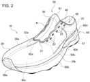
- FIG. 2 is a perspective view of the shoe viewed obliquely from a front left side.
- FIG. 2 illustrates the state where the shoelace 30 is removed.
- the sole 60 is configured such that a midsole 60b and an inner sole 60c are overlaid in this order and bonded onto an outsole 60a, which is a portion to be in contact with the ground, and a heel counter 60d is also bonded at the position of the heel. Since the inner sole 60c is provided inside the upper 20 and invisible from the outside, it is indicated by dotted lines in the drawing.
- the shoe tongue 50 is indicated by solid lines for the portion exposed through the instep opening 41 and by dotted lines for the portions hidden by the upper 20.
- the top surface contour of the midsole 60b is also indicated by dotted lines for the medial side portion hidden by the upper 20.
- a sock liner is inserted into the internal space 40 and laid on the bottom, i.e., on the inner sole 60c.
- the shoe tongue 50 forms an inverted V shape in the ridge portion 56 located in the middle on the top surface.
- the inverted V shape of the ridge portion 56 is formed such that it warps along a direction from the toe to a tip part 51, as illustrated. This naturally facilitates widening of the foot insertion opening 42 and also facilitates the wearer's foot insertion into the foot insertion opening 42.
- the tip part 51 is formed thicker than other adjacent portions in the shoe tongue 50.
- a medial side end of the upper 20 and the sole 60 are joined at a medial side tangent 24a, and a lateral side end of the upper 20 and the sole 60 are joined at a lateral side tangent 24b.
- a medial side end 52a of the shoe tongue 50 is sewn to the upper 20 near the medial side tangent 24a, and a lateral side end 52b of the shoe tongue 50 is sewn to the upper 20 near the lateral side tangent 24b.
- the outline of the inner sole 60c is one size smaller than the outline of the midsole 60b, and a dotted line indicating the outline of the inner sole 60c is drawn inside the medial side tangent 24a and the lateral side tangent 24b.
- the medial side end 52a of the shoe tongue 50 is sewn to the inner sole 60c at the position of a medial side tangent 62a along the outline of the inner sole 60c
- the lateral side end 52b of the shoe tongue 50 is sewn to the inner sole 60c at the position of a lateral side tangent 62b along the outline of the inner sole 60c.
- the tip part 51 is formed in a crescent shape with both ends extending downward. Each of the both ends extending downward of the tip part 51 is located at a position overlapping and hidden by the upper 20 and also overlaps an eyelet 23 positioned closer to the ankle when the shoelace 30 is tightened and tied, i.e., positioned at the uppermost end. Accordingly, the eyelet 23 (especially the metal eyelet) positioned at the uppermost end, with which the wearer often feels tightening of the shoelace 30, is less likely to come into direct contact with the instep, so that improved wearing comfort provided by protecting the instep can be expected.
- the medial side end 52a and the lateral side end 52b may be joined to the sole 60 by means of bonding or the like, instead of sewing. Also, as another modification, the medial side end 52a and the lateral side end 52b may be joined to the upper 20, instead of the sole 60, near the tangent between the sole 60 and the upper 20.
- the end part of the shoe tongue 50 located at the front, is sewn to the opening end 21 of the upper 20, which forms the instep opening 41.
- An outer edge portion 57 adjacent to the lateral side end 52b of the shoe tongue 50 is sewn to an inner fabric 22, which is a mesh member, near the foot insertion opening 42, and the shoe tongue 50 and the inner fabric 22 integrally form an inner wall of the internal space 40 near the opening end 21.
- FIG. 3 is a perspective view that shows a joint state of the sole 60 and the shoe tongue 50.
- FIG. 3 illustrates the state where the upper 20, shoelace 30, and heel counter 60d are removed.
- the medial side tangent 24a and the lateral side tangent 24b almost coincide with the top surface contour of the midsole 60b.
- the inner sole 60c is bonded slightly inside the medial side tangent 24a and the lateral side tangent 24b, forming a bottom part of the internal space 40 formed by the upper 20.
- the hem of the upper 20 is bonded along the top surface contour of the midsole 60b such as to be sandwiched between the outer circumference of the lower surface of the inner sole 60c and the midsole 60b.
- the hem of the upper 20 is sewn to the inner sole 60c, along the top surface contour of the inner sole 60c.
- the medial side tangent 62a where the medial side end 52a and the inner sole 60c are sewn together and the lateral side tangent 62b where the lateral side end 52b and the inner sole 60c are sewn together are indicated by diagonal lines.
- the medial side end 52a and the lateral side end 52b are sewn to the inner sole 60c.
- the inverted V shape of the ridge portion 56 is formed such that it warps upward from an end part 59 on the front side (toe side) to the tip part 51, as indicated by a highlighted line S. This naturally facilitates widening of the foot insertion opening 42 and also facilitates the wearer's foot insertion into the foot insertion opening 42.
- the shoe tongue 50 is a component independent of the upper 20 and woven to have a three-dimensional shape that fits the instep by itself. With the medial side end 52a and the lateral side end 52b joined to the sole 60, the shoe tongue 50 independently extends upward. Also, since the shoe tongue 50, which is a knitted member with high stretchability, wraps around not only the instep but also the entire midfoot portion, the fit of the shoe tongue 50 to the midfoot portion can be enhanced. Also, since the ridge portion 56 has a shape such that it warps along a direction from the toe to the tip part 51, the foot insertion opening 42 can be widened easily.
- the shoe tongue 50 This reduces the possibility of the shoe tongue 50 being brought inside the shoe 10 due to friction with the foot when the wearer inserts the foot, thereby facilitating the foot insertion. Further, since the shoe tongue 50 extends upward, the pressing force applied to the wearer's instep can be reduced. Since the three-dimensional shape is provided at the manufacturing stage of the shoe tongue 50, the ridge portion can be made free from seams, which would be unavoidable if the three-dimensional shape were provided in secondary processing, so that the smoothness for a foot can be made favorable. In addition, the disadvantages of providing the three-dimensional shape in secondary processing, such as complicated manufacturing processes and loss of materials due to cutting, can be avoided in the present embodiment.
- FIG. 4 is a side view that shows a state where the wearer has inserted the foot into the shoe.
- the wearer bends the joint of an ankle 70 forward, i.e., bends the ankle joint such that the angle between the ankle and the instep becomes smaller, the front surface of the ankle 70 touches the inner surface of the tip part 51 of the shoe tongue 50.
- the wearer may feel strong tightening at the ankle. Since the tip part 51 of the present embodiment is formed thicker than other adjacent portions in the shoe tongue 50, the smoothness for a foot of the shoe tongue 50 can be made favorable. Also, the stretchability and elasticity of the shoe tongue 50 can reduce the feeling of tightness at the ankle.
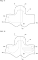
- FIG. 5 is a bottom view of the shoe tongue 50 in a spread state in the first embodiment.
- the shoe tongue 50 of the present embodiment is configured to include the tip part 51 extending upward in FIG. 5 in an upper semicircular shape, the medial side end 52a extending toward the medial side in a quadrangular shape, the lateral side end 52b extending toward the lateral side in a quadrangular shape, the end part 59 extending downward in FIG. 5 in a wavy shape, and a portion near the ridge portion 56.
- the medial side end 52a is sewn to the inner sole 60c at the medial side tangent 62a
- the lateral side end 52b is sewn to the inner sole 60c at the lateral side tangent 62b.
- the end part 59 is sewn to the upper 20 at the opening end 21.
- An outer edge portion 57a which is the top side of the medial side end 52a adjacent to the medial side tangent 62a, and an outer edge portion 57b, which is the top side of the lateral side end 52b adjacent to the lateral side tangent 62b, are sewn to the inner fabric 22 in the internal space 40.
- multiple regions having different stretchability and different thicknesses can be integrally formed in a single shoe tongue 50, by changing the materials and thicknesses of knitting yarns, the knitting method, and the like used for each region.
- multiple regions of a high stretch region, a medium stretch region, and a low stretch region divided based on the stretchability are integrally formed.
- an inverted V shape forming a mountain-like shape is made along the center line.
- a central high stretch region 55c of triangular shape which is long in the front and rear directions, is provided to extend downward from the vicinity of the center of the shoe tongue 50 along the ridge portion 56, and a medial side high stretch region 55a and a lateral side high stretch region 55b are also provided respectively on both sides of the central high stretch region 55c to extend on the medial side and the lateral side.
- the medial side high stretch region 55a is disposed on the medial side of the ridge portion 56 and has a shape extending, from a position between the lower right end of the low stretch region 53 and the ridge portion 56, downward to the right and then toward the medial side in a width direction.
- the lateral side high stretch region 55b is disposed on the lateral side of the ridge portion 56 and has a shape extending, from a position between the lower left end of the low stretch region 53 and the ridge portion 56, downward to the left and then toward the lateral side in a width direction.
- the high stretch regions 55 are formed to have higher stretchability than adjacent surrounding regions.
- Each high stretch region 55 is formed by weaving a knitting yarn of polyurethane elastic fiber (so-called spandex), for example, as a knitting yarn having high stretchability.
- spandex polyurethane elastic fiber
- a suitable thickness of spandex used for the high stretch regions 55 may be, for example, 100 to 350 denier.
- Each high stretch region 55 is woven with coarse density so as to be thinner than the low stretch region 53.
- the shoe tongue 50 has a recess 58 formed in an arc shape on part of a circumferential edge that continues from the tip part 51 to each of the side ends on the medial side and the lateral side.
- the arc degree of the arc forming each recess 58 is smaller than ⁇ rad.
- a deep cut needs to be provided at a position corresponding to each recess 58 of the present embodiment so that the tip part can be pulled and moved more easily.
- the fit to the instep may be reduced because of the deep cuts.
- each recess 58 has a relatively large radius of curvature, and a shallow recess formed by an arc with an arc degree of less than ⁇ rad will suffice. In this case, the area covering the instep becomes larger because there is no deep cut, and the fit to the instep can be improved.
- FIG. 6 schematically illustrates a cross section of the shoe tongue taken along line A-A in FIG. 5 .
- the shoe tongue 50 is a knitted member of which the surface is formed by continuous loops made by continuously hooking, onto a minute loop of a knitting yarn, the subsequent loop of the knitting yarn. From the left in FIG. 6 , the low stretch region 53, the medium stretch region 54, a high stretch region 55, and the medium stretch region 54 are shown.
- the low stretch region 53 is formed by tight weaving so as to be thicker than other regions, using a knitting yarn having lower stretchability than the knitting yarns for other regions.
- Each high stretch region 55 is formed by weaving a spandex knitting yarn having high stretchability. Each high stretch region 55 is woven with coarse density so as to be thinner than the low stretch region 53.
- the medium stretch region 54 is formed more stretchable than the low stretch region 53 and less stretchable than the high stretch regions 55.
- the medium stretch region 54 may be formed by weaving a spandex knitting yarn thinner than that used for a high stretch region 55.
- the medium stretch region 54 is woven with density such that the region has a thickness intermediate between the thicknesses of a high stretch region 55 and the low stretch region 53.
- the multiple regions are integrally formed into a single knitted member.
- the present embodiment differs from the first embodiment in the arrangement of stretch regions in the shoe tongue 50.
- description will be given mainly for the differences from the first embodiment, and the explanation of features in common will be omitted.
- a shoe tongue with different functions can be realized by a single shoe tongue.
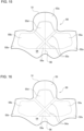
- FIG. 7 is a bottom view of the shoe tongue 50 in a spread state in the second embodiment.
- the present embodiment differs from the first embodiment in that the medial side high stretch region is not provided on the medial side (the right side in FIG. 7 ).
- the position where the medial side high stretch region 55a is provided in the first embodiment corresponds to part of the medium stretch region 54 in the present embodiment, which has lower stretchability than the lateral side high stretch region 55b located in the symmetrical position. This can make the medial side less stretchable and more rigid than the lateral side, thereby preventing excessive pronation due to collapse of the arch.
- the present embodiment differs from the first embodiment in the shape of a stretch region in the shoe tongue 50.
- description will be given mainly for the differences from the first embodiment, and the explanation of features in common will be omitted.
- FIG. 8 is a bottom view of the shoe tongue 50 in a spread state in the third embodiment.
- the shape of the low stretch region 53 in the tip part 51 is different from that of the first embodiment. More specifically, the present embodiment differs from the first embodiment in that, while the low stretch region 53 of the first embodiment is crescent-shaped, the low stretch region 53 of the third embodiment includes a central downward extending portion 53b that extends downward from a center part of a crescent-shaped portion 53a to the upper end of the central high stretch region 55c along the ridge portion 56, so that the low stretch region 53 has an overall shape similar to a T-shape. This can increase the thick area along the ridge portion 56, thereby further reducing the feeling of tightness on the instep when the shoelace 30 is tightened.
- the present embodiment differs from the third embodiment in the arrangement of stretch regions in the shoe tongue 50.
- description will be given mainly for the differences from the third embodiment, and the explanation of features in common will be omitted.
- FIG. 9 is a bottom view of the shoe tongue 50 in a spread state in the fourth embodiment.
- the present embodiment differs from the third embodiment in that the medial side high stretch region is not provided on the medial side (the right side in FIG. 9 ).
- the position where the medial side high stretch region 55a is provided in the third embodiment corresponds to part of the medium stretch region 54 in the present embodiment, which has lower stretchability than the lateral side high stretch region 55b located in the symmetrical position. This can make the medial side less stretchable and more rigid than the lateral side, thereby preventing excessive pronation due to collapse of the arch.
- the present embodiment differs from the first embodiment in the shapes and arrangement of stretch regions in the shoe tongue 50.
- description will be given mainly for the differences from the first embodiment, and the explanation of features in common will be omitted.
- FIG. 10 is a bottom view of the shoe tongue 50 in a spread state in the fifth embodiment.
- the high stretch region 55 of the present embodiment is not divided into multiple regions and has the size, position, and shape such that it covers all of the medial side high stretch region 55a, the lateral side high stretch region 55b, and the central high stretch region 55c in the first embodiment. This can achieve stretchability equal to or higher than that in the first embodiment and can also provide the same effect as the first embodiment.
- the low stretch region 53 in the present embodiment has a crescent shape as in the first embodiment.
- the low stretch region 53 in a modification may have a shape similar to a T-shape formed such that a center part of a crescent shape extends downward along the ridge portion 56 to the vicinity of the center of the shoe tongue 50, as with the low stretch region 53 in the third and fourth embodiments.
- the low stretch region 53 of crescent shape when the low stretch region 53 of crescent shape is described as an example, the low stretch region 53 of T-shape may also be used as a modification.
- the low stretch region 53 of crescent shape may also be used as a modification.
- the present embodiment differs from the fifth embodiment in the shapes and arrangement of stretch regions in the shoe tongue 50.
- description will be given mainly for the differences from the fifth embodiment, and the explanation of features in common will be omitted.
- FIG. 11 is a bottom view of the shoe tongue 50 in a spread state in the sixth embodiment.
- the present embodiment differs from the fifth embodiment in that no high stretch region is provided on the medial side (the right side in FIG. 11 ).
- the high stretch region 55 of the present embodiment has a shape such that a medial side area is removed from the high stretch region 55 in the fifth embodiment and covers a lateral side area and a center area along the ridge portion 56.
- the medial side area in the present embodiment is part of the medium stretch region 54 and has lower stretchability than the lateral side area and the center area. This can make the medial side less stretchable and more rigid than the lateral side and the center area, thereby preventing excessive pronation due to collapse of the arch.
- the present embodiment differs from the first embodiment in the shapes and arrangement of stretch regions in the shoe tongue 50.
- description will be given mainly for the differences from the first embodiment, and the explanation of features in common will be omitted.
- the stretchability is higher compared to a configuration in which no high stretch region is provided on the entire medial side surface, as in the second and fourth embodiments; however, compared to the lateral side on which the lateral side high stretch region 55b is provided, the stretchability is slightly lower in the midfoot portion. Further, a center portion along the ridge portion 56 is also not provided with a high stretch region. This can strengthen the tightening in the midfoot portion and prevent excessive pronation due to collapse of the arch.
- the center portion along the ridge portion 56 is not provided with a high stretch region but may be provided, in a modification, with a central high stretch region similar to that in the first embodiment.
- the present embodiment differs from the seventh embodiment in the shapes and arrangement of stretch regions in the shoe tongue 50.
- description will be given mainly for the differences from the seventh embodiment, and the explanation of features in common will be omitted.
- FIG. 13 is a bottom view of the shoe tongue 50 in a spread state in the eighth embodiment.
- the eighth embodiment differs from the seventh embodiment in that, while the medial side high stretch region 55a is divided into multiple regions in the seventh embodiment, the lateral side high stretch region 55b is also divided into multiple regions.
- the lateral side high stretch region 55b in the present embodiment also has a shape divided into multiple parts by multiple band-shaped slits provided along the left and right directions at positions corresponding to the midfoot portion of the wearer. Each slit portion is part of the medium stretch region 54 and has lower stretchability than the medial side high stretch region 55a and the lateral side high stretch region 55b.
- a center portion along the ridge portion 56 is also not provided with a high stretch region. This can strengthen the tightening in the midfoot portion and restrain sidewise shifts of the foot.
- the center portion along the ridge portion 56 is not provided with a high stretch region but may be provided, in a modification, with a central high stretch region similar to that in the first embodiment.
- the present embodiment differs from the third embodiment in the shapes and arrangement of stretch regions in the shoe tongue 50.
- description will be given mainly for the differences from the third embodiment, and the explanation of features in common will be omitted.
- FIG. 14 is a bottom view of the shoe tongue 50 in a spread state in the ninth embodiment.
- the low stretch region 53 is constituted by the crescent-shaped portion 53a and the central downward extending portion 53b, and the low stretch region 53 as a whole has a T-shape, in the same way as the low stretch region 53 of the third embodiment.
- the present embodiment differs from the third embodiment in that the central downward extending portion 53b of the low stretch region 53 extends downward to a position near the lower end of the shoe tongue 50, i.e., a position near the lower ends of the medial side high stretch region 55a and the lateral side high stretch region 55b.
- the central downward extending portion 53b of the present embodiment is formed in a band shape that maintains almost the same width along the low stretch region 53 and extends downward to a position near the lower ends of the medial side high stretch region 55a and the lateral side high stretch region 55b.
- the end on the ridge portion 56 side of the medial side high stretch region 55a extends leftward to a position near the ridge portion 56, i.e., a position adjacent to the central downward extending portion 53b without a gap.
- the end on the ridge portion 56 side of the lateral side high stretch region 55b extends rightward to a position near the ridge portion 56, i.e., a position adjacent to the central downward extending portion 53b without a gap.
- the present embodiment differs from the fifth embodiment in the shapes and arrangement of stretch regions in the shoe tongue 50.
- description will be given mainly for the differences from the fifth embodiment, and the explanation of features in common will be omitted.
- FIG. 15 is a bottom view of the shoe tongue 50 in a spread state in the tenth embodiment.
- the overall contour of the high stretch region 55 in the present embodiment coincides with the overall contour of the high stretch region 55 in the fifth embodiment.
- the present embodiment differs from the fifth embodiment in that a low stretch region formed by two band-shaped portions intersecting diagonally is provided in a center portion of the high stretch region 55.
- An intersecting band-shaped portion 53c is a low stretch region formed by two intersecting band-shaped portions extending diagonally downward respectively from positions near the lower ends on the both sides of the crescent-shaped portion 53a to the opposite sides across the ridge portion 56. As with the crescent-shaped portion 53a, the intersecting band-shaped portion 53c is thicker than other adjacent portions.
- the high stretch region 55 is divided into four regions by the intersecting band-shaped portion 53c.
- the four divided regions are, besides the medial side high stretch region 55a positioned on the medial side and the lateral side high stretch region 55b position on the lateral side, a central upper high stretch region 55d positioned in an upper part along the ridge portion 56, and a central lower high stretch region 55e positioned in a lower part along the ridge portion 56.
- the present embodiment differs from the tenth embodiment in the shapes and arrangement of stretch regions in the shoe tongue 50.
- description will be given mainly for the differences from the tenth embodiment, and the explanation of features in common will be omitted.
- FIG. 16 is a bottom view of the shoe tongue 50 in a spread state in the eleventh embodiment.
- the low stretch region of the intersecting band-shaped portion 53c in the tenth embodiment is replaced with a medium stretch region.
- an intersecting band-shaped portion 54a is provided, which is a medium stretch region formed by two intersecting band-shaped portions extending diagonally downward respectively from positions near the lower ends on the both sides of the crescent-shaped portion 53a to the opposite sides across the ridge portion 56.
- the high stretch region 55 is divided into four regions by the intersecting band-shaped portion 54a.
- the four divided regions are, besides the medial side high stretch region 55a positioned on the medial side and the lateral side high stretch region 55b position on the lateral side, the central upper high stretch region 55d positioned in an upper part along the ridge portion 56, and the central lower high stretch region 55e positioned in a lower part along the ridge portion 56.
- sidewise shifts can be restrained by wrapping around the midfoot portion more strongly, as in the tenth embodiment.
- the present embodiment differs from the third embodiment in the shapes and arrangement of stretch regions in the shoe tongue 50.
- description will be given mainly for the differences from the third embodiment, and the explanation of features in common will be omitted.
- FIG. 17 is a bottom view of the shoe tongue 50 in a spread state in the twelfth embodiment.
- the present embodiment differs from the third embodiment in that a hollow part is formed in the medial side high stretch region 55a of the third embodiment to occupy most of an area from the vicinity of the ridge portion 56 toward the medial side end 52a, and, in the hollow part, a medium stretch region is provided as a medial side partial medium stretch region 54b.
- the present embodiment can also make the medial side less stretchable and more rigid than the lateral side, thereby preventing excessive pronation due to collapse of the arch.
- the present embodiment differs from the third embodiment in the shapes and arrangement of stretch regions in the shoe tongue 50.
- description will be given mainly for the differences from the third embodiment, and the explanation of features in common will be omitted.
- FIG. 18 is a bottom view of the shoe tongue 50 in a spread state in the thirteenth embodiment.
- the present embodiment differs from the third embodiment in that the medial side high stretch region 55a is formed in a shape such that multiple diagonal slits are added to the medial side high stretch region 55a of the third embodiment. More specifically, the medial side high stretch region 55a of the present embodiment is divided into multiple regions by slit-shaped medium stretch regions 54c, which are three diagonal slits. The three slit-shaped medium stretch regions 54c constitute part of the medium stretch region 54.
- the medial side in the present embodiment as a whole is more stretchable than the medium stretch region 54 and less stretchable than the lateral side high stretch region 55b.
- the present embodiment can also make the medial side less stretchable and more rigid than the lateral side, thereby preventing excessive pronation due to collapse of the arch.
- the present embodiment differs from the third embodiment in the shape of a stretch region in the shoe tongue 50.
- description will be given mainly for the differences from the third embodiment, and the explanation of features in common will be omitted.
- FIG. 19 is a bottom view of the shoe tongue 50 in a spread state in the fourteenth embodiment.
- the medial side high stretch region 55a of the present embodiment is about half the size of the medial side high stretch region 55a of the third embodiment. More specifically, when the medial side high stretch region 55a of the third embodiment is divided into two halves by a virtual center line CM extending along the front and rear directions, the medial side high stretch region 55a of the present embodiment has a shape and size corresponding to the half of the ridge portion 56 side, and the half of the medial side of the virtual center line CM is not provided with a high stretch region and constitutes part of the medium stretch region 54.
- the present embodiment can also make the medial side less stretchable and more rigid than the lateral side, thereby preventing excessive pronation due to collapse of the arch.
- the present embodiment differs from the third embodiment in the shape of a stretch region in the shoe tongue 50.
- description will be given mainly for the differences from the third embodiment, and the explanation of features in common will be omitted.
- FIG. 20 is a bottom view of the shoe tongue 50 in a spread state in the fifteenth embodiment.
- the lateral side high stretch region 55b of the present embodiment is larger than the lateral side high stretch region 55b of the third embodiment and extends leftward to an edge of the lateral side end 52b.
- the present embodiment can also make the medial side less stretchable and more rigid than the lateral side where the area of the high stretch region is larger, thereby preventing excessive pronation due to collapse of the arch.
- the present embodiment differs from the third and fourteenth embodiments in the shape of a stretch region in the shoe tongue 50.
- description will be given mainly for the differences from the third and fourteenth embodiments, and the explanation of features in common will be omitted.
- FIG. 21 is a bottom view of the shoe tongue 50 in a spread state in the sixteenth embodiment.
- the medial side high stretch region 55a is about half the size of the medial side high stretch region 55a of the third embodiment, in the same way as in the fourteenth embodiment.
- the sixteenth embodiment differs from the fourteenth embodiment in that, while the boundary between the medial side end of the medial side high stretch region 55a and the medium stretch region in the fourteenth embodiment is clear, the boundary between the medial side end of the medial side high stretch region 55a and the medium stretch region in the sixteenth embodiment is formed in a gradation-like pattern to be made ambiguous.
- the medial side high stretch region 55a of the present embodiment is formed such that the stretchability thereof gradually decreases from the ridge portion 56 side toward the medial side.
- the present embodiment can also make the medial side less stretchable and more rigid than the lateral side, thereby preventing excessive pronation due to collapse of the arch.
- the shoe tongue is configured such that the stretchability thereof changes in stages from the high stretch region to the medium stretch region, the arch can be supported with less incongruity, and the fit can be improved.
- the present embodiment differs from the fourth embodiment in the shape of a stretch region in the shoe tongue 50.
- description will be given mainly for the differences from the fourth embodiment, and the explanation of features in common will be omitted.
- FIG. 22 is a bottom view of the shoe tongue 50 in a spread state in the seventeenth embodiment.
- the present embodiment is the same as the fourth embodiment in that the medial side high stretch region is not provided, but the lateral side high stretch region 55b of the present embodiment is different in shape from the lateral side high stretch region 55b of the fourth embodiment.
- the lateral side high stretch region 55b of the present embodiment is formed such that the boundary with the adjacent medium stretch region is formed in a gradation-like pattern to be made ambiguous and such that the stretchability of the lateral side high stretch region 55b gradually decreases from the lateral side toward the ridge portion 56.
- the present embodiment can also make the medial side less stretchable and more rigid than the lateral side, thereby preventing excessive pronation due to collapse of the arch.
- the shoe tongue is configured such that the stretchability thereof changes in stages from the high stretch region to the medium stretch region, the stability of the midfoot portion can be enhanced with less incongruity, and the fit can be improved.
- the present embodiment differs from the third embodiment in the shapes and arrangement of stretch regions in the shoe tongue 50.
- description will be given mainly for the differences from the third embodiment, and the explanation of features in common will be omitted.
- FIG. 24 is a bottom view of the shoe tongue 50 in a spread state in the nineteenth embodiment.
- the stretch regions are arranged based on the prominent portion of the instep bones of a human foot such as to flow from the center of the instep in front of the ankle toward the toe on the medial side, in the same way as in the eighteenth embodiment.
- the medial side band portion 54d flowing from the vicinity of the ridge portion 56 toward the medial side is provided as a band-like medium stretch region, but a region like the middle band portion 54e in the eighteenth embodiment is not provided.
- the medium stretch region is disposed along the prominent portion of the instep bones, and, by arranging the high stretch regions on both sides of the medium stretch region, the arrangement of stretch regions considering the foot bones can be made, thereby improving the fit to the instep.
Landscapes
- Engineering & Computer Science (AREA)
- Textile Engineering (AREA)
- Footwear And Its Accessory, Manufacturing Method And Apparatuses (AREA)
Abstract
Description
- The present disclosure relates to a shoe.
- Conventionally, the purposes of providing a shoe tongue in a shoe are mainly to cover the wearer's instep portion to prevent soil and dust from entering inside the shoe and also to protect the instep portion from tightening pressure from a shoelace (see Patent Literatures 1 and 2, for example).
-
- Patent Literature 1:
Japanese Unexamined Patent Application Publication No. 2019-130370 - Patent Literature 2:
Japanese Patent No. 5950479 - Depending on the design for improvement in the fit of a shoe tongue to the instep, the shoe tongue may be drawn into the shoe due to friction with the instep when the foot is inserted, or the wearer's foot may feel tight when it is inserted.
- The present disclosure has been made in view of such a problem, and a purpose thereof is to provide a shoe that achieves both the ease of foot insertion and the fit to a foot shape.
- To solve the problem above, a shoe according to one aspect of the present disclosure includes a sole, an upper joined to the sole, and a shoe tongue provided in a space formed by the sole and the upper. The shoe tongue is formed of a knitted member and includes a ridge portion of inverted V shape along the front and rear directions of the shoe.
- The "shoe" herein may be, for example, a type of shoe with a shoelace tightened and tied, such as a running shoe. The "upper" may be formed of a mesh member or a knitted member, for example. The "ridge portion" may have an inverted V shape folded to form a mountain-like shape prominent upward, in a middle part of the top surface of the shoe tongue along the front and rear directions. The inverted V portion may be sharply folded so that the fold is clearly recognized.
- According to this aspect, since the shoe tongue is formed in an inverted V shape folded to form a mountain-like shape prominent upward, the opening for foot insertion can be made wider compared to the case of a conventional flat shoe tongue. Therefore, the area where friction between the shoe tongue and a foot occurs when the foot is inserted can be made smaller, making the shoe tongue less likely to get brought inside the shoe. Even with the inverted V shape, since the shoe tongue is formed of a flexible knitted member, it will be flat and fit the instep when a foot is inserted and the shoelace is tightened.
- The shoe tongue may be formed of a single knitted member of sheet shape of which side ends on the medial side and the lateral side are each joined to the vicinity of a tangent between a bottom part and a side part in the space. The "being joined" may be, for example, being connected by means of sewing, bonding, vapor deposition, or the like. According to this aspect, since the both side ends of the shoe tongue are each joined to the vicinity of a tangent between the bottom part and a side part in the space, the shoe tongue can be made to fit the instep more easily such as to wrap around the entire midfoot portion.
- In the shoe tongue, part of an area from the ridge portion to the side end on the medial side or the lateral side may be formed to have higher stretchability than at least part of other adjacent areas. According to this aspect, by providing highly stretchable regions from the ridge to the foot width directions, the shoe tongue can be made to fit to the foot width of each wearer more easily.
- The shoe tongue may include a recess formed in an arc shape on part of a circumferential edge that continues from a tip part of the shoe tongue to each of the side ends on the medial side and the lateral side, and the arc degree of the arc forming the recess may be smaller than π radian. According to this aspect, the ease of movement of the tip part can be ensured without deep cuts as provided in a conventional case. Only by providing a shallow recess formed by an arc with an arc degree of less than π radian, the tip part can be moved more easily. Also, the area covering the instep becomes larger because there is no deep cut, and the fit to the instep can be improved.
- In the shoe tongue, the tip part may be formed thicker than at least part of other adjacent portions. According to this aspect, the smoothness for a foot of the shoe tongue can be made favorable, and the feeling of tightness at the ankle can be reduced.
- A thick portion of the tip part may be formed in a crescent shape in plan view, and each of the both ends of the crescent shape may extend toward the toe. Each of the both ends of the tip part may be located at a position overlapping and hidden by the upper and also overlapping an eyelet positioned closer to the ankle when the shoelace is tightened and tied, i.e., positioned at the uppermost end. According to this aspect, the eyelet (especially the metal eyelet) positioned at the uppermost end, with which the wearer often feels tightening of the shoelace, is less likely to come into direct contact with the instep, so that improved wearing comfort provided by protecting the instep can be expected.
-
-
FIG. 1 is a schematic top view of a shoe according to a first embodiment. -
FIG. 2 is a perspective view of the shoe viewed obliquely from a front left side. -
FIG. 3 is a perspective view that shows a joint state of a sole and a shoe tongue. -
FIG. 4 is a side view that shows a state where the wearer has inserted the foot into the shoe. -
FIG. 5 is a bottom view of the shoe tongue in a spread state in the first embodiment. -
FIG. 6 is a schematic diagram of a cross section of the shoe tongue taken along line A-A inFIG. 5 . -
FIG. 7 is a bottom view of the shoe tongue in a spread state in a second embodiment. -
FIG. 8 is a bottom view of the shoe tongue in a spread state in a third embodiment. -
FIG. 9 is a bottom view of the shoe tongue in a spread state in a fourth embodiment. -
FIG. 10 is a bottom view of the shoe tongue in a spread state in a fifth embodiment. -
FIG. 11 is a bottom view of the shoe tongue in a spread state in a sixth embodiment. -
FIG. 12 is a bottom view of the shoe tongue in a spread state in a seventh embodiment. -
FIG. 13 is a bottom view of the shoe tongue in a spread state in an eighth embodiment. -
FIG. 14 is a bottom view of the shoe tongue in a spread state in a ninth embodiment. -
FIG. 15 is a bottom view of the shoe tongue in a spread state in a tenth embodiment. -
FIG. 16 is a bottom view of the shoe tongue in a spread state in an eleventh embodiment. -
FIG. 17 is a bottom view of the shoe tongue in a spread state in a twelfth embodiment. -
FIG. 18 is a bottom view of the shoe tongue in a spread state in a thirteenth embodiment. -
FIG. 19 is a bottom view of the shoe tongue in a spread state in a fourteenth embodiment. -
FIG. 20 is a bottom view of the shoe tongue in a spread state in a fifteenth embodiment. -
FIG. 21 is a bottom view of the shoe tongue in a spread state in a sixteenth embodiment. -
FIG. 22 is a bottom view of the shoe tongue in a spread state in a seventeenth embodiment. -
FIG. 23 is a bottom view of the shoe tongue in a spread state in an eighteenth embodiment. -
FIG. 24 is a bottom view of the shoe tongue in a spread state in a nineteenth embodiment. - The disclosure will now be described by reference to the preferred embodiments. This does not intend to limit the scope of the present invention, but to exemplify the invention.
- In the following, the present disclosure will be described based on preferred embodiments with reference to each drawing. In the embodiments and modifications, like reference characters denote like or corresponding constituting elements and members, and the repetitive description will be omitted as appropriate. Also, the dimensions of a member may be appropriately enlarged or reduced in each drawing in order to facilitate understanding. In each drawing, part of a member less important in describing embodiments may be omitted.
-
FIG. 1 is a schematic top view of a shoe according to the first embodiment. In the following, a configuration of ashoe 10 according to the present embodiment will be described with reference to the drawings. Each drawing mentioned below, includingFIG. 1 , illustrates a shoe and components thereof for a left foot, unless otherwise specified. However, the description in the present specification is also similarly applicable to a shoe and components thereof for a right foot. - The
shoe 10 of the present embodiment is a laced shoe used for sports such as running or walking. Theshoe 10 includes an upper 20, ashoelace 30, ashoe tongue 50, and a sole 60. The right side of a center line C with respect to a foot width direction of theshoe 10 inFIG. 1 is referred to as a "medial side", and the left side of the center line C inFIG. 1 is referred to as a "lateral side". In the case of a right-foot shoe, the medial side and the lateral side are reversed from left to right. The arrow W pointing to the left and right inFIG. 1 indicates foot width directions, and the arrow L pointing upward and downward inFIG. 1 indicates the front and rear directions of theshoe 10. - The upper 20 is joined, at its hem, to the sole 60 to form an
internal space 40 for accommodating a wearer's foot. Also, aninstep opening 41 is formed at a position corresponding to the wearer's instep in an upper front part of theshoe 10, and afoot insertion opening 42, into which the wearer inserts the foot, is formed in an upper rear part of theshoe 10. When the wearer puts theshoe 10 on, the upper 20 wraps the entire top portion of the foot. The upper 20 and the sole 60 are joined together by means of bonding or the like. - The
shoe tongue 50 is provided such as to close theinstep opening 41 from the inner side of the upper 20, i.e., from theinternal space 40 side, and covers an area from a front part of the ankle to the instep of the wearer. Theshoe tongue 50 is a component independent of the upper 20, and an end part of theshoe tongue 50 is sewn to an openingend 21 of the upper 20, which forms the front end of theinstep opening 41. A tip part of theshoe tongue 50 comes into contact with the front of the ankle when the foot is inserted. - The
shoelace 30 is made to pass throughmultiple eyelets 23 and intersect on theshoe tongue 50. When theshoelace 30 is tightened, downward pressing force caused by the tightening force is applied to the wearer's instep via theshoe tongue 50, so that theshoe tongue 50 fits the wearer's instep. AlthoughFIG. 1 illustrates a type of shoe that is tightened with theshoelace 30 passed through theeyelets 23, it may also be a type of shoe that is tightened by hooking theshoelace 30 onto hooks, a type of shoe that is tightened with a dial-type shoelace, or a type of shoe that is tightened with a hook-and-loop fastener. - The
shoe tongue 50 is formed as a single knitted member by interweaving multiple types of knitting yarns having different properties, such as the material and thickness. Theshoe tongue 50 includes aridge portion 56 extending along front and rear directions L at a substantially middle position in top view, i.e., at a position almost along the center line C. Theridge portion 56 has an inverted V shape folded to form a mountain-like shape prominent upward, and theshoe tongue 50 is formed with an interweaving method to have a three-dimensional shape such that such an inverted V shape remains in the middle. The inverted V shape of theridge portion 56 may be made by sharp folding so that the fold is clearly recognized. - When the
shoelace 30 is tightened, tightening force is generated from both the medial side and the lateral side toward the center line C, as indicated by tightening directions T inFIG. 1 . The tightening force then becomes downward pressing force and is applied to the top surface of theshoe tongue 50, so that theshoe tongue 50 is pressed against the instep. Also, theshoe tongue 50 is a component independent of the upper 20, and, as will be described later, both side ends of theshoe tongue 50 are sewn to an inner sole of the sole 60 in theinternal space 40, so as to be pulled in foot width directions W; with the stretchability and flexibility of the knitted member, theshoe tongue 50 fits the entire instep side of the wearer's midfoot portion. In the case of a conventional integral structure in which the upper 20 and theshoe tongue 50 are integrally formed, when the shoelace is tightened, there is no place for the upper or the shoe tongue to escape under the shoe lace, which may cause wrinkling of the upper or shoe tongue on the instep. In contrast, theshoe tongue 50 of the present embodiment is joined, at its side ends extending toward the medial side and the lateral side, to the inner sole and can spread in the foot width directions, thereby preventing deformation such that theshoe tongue 50 is pulled and gathered toward the vicinity of the center line C when theshoelace 30 is tightened. -
FIG. 2 is a perspective view of the shoe viewed obliquely from a front left side.FIG. 2 illustrates the state where theshoelace 30 is removed. The sole 60 is configured such that amidsole 60b and an inner sole 60c are overlaid in this order and bonded onto anoutsole 60a, which is a portion to be in contact with the ground, and aheel counter 60d is also bonded at the position of the heel. Since the inner sole 60c is provided inside the upper 20 and invisible from the outside, it is indicated by dotted lines in the drawing. Theshoe tongue 50 is indicated by solid lines for the portion exposed through theinstep opening 41 and by dotted lines for the portions hidden by the upper 20. The top surface contour of themidsole 60b is also indicated by dotted lines for the medial side portion hidden by the upper 20. In an actual product, a sock liner, not illustrated, is inserted into theinternal space 40 and laid on the bottom, i.e., on the inner sole 60c. - The
shoe tongue 50 forms an inverted V shape in theridge portion 56 located in the middle on the top surface. In a state where a foot is not inserted into theshoe 10, the inverted V shape of theridge portion 56 is formed such that it warps along a direction from the toe to atip part 51, as illustrated. This naturally facilitates widening of thefoot insertion opening 42 and also facilitates the wearer's foot insertion into thefoot insertion opening 42. Thetip part 51 is formed thicker than other adjacent portions in theshoe tongue 50. - A medial side end of the upper 20 and the sole 60 are joined at a medial side tangent 24a, and a lateral side end of the upper 20 and the sole 60 are joined at a lateral side tangent 24b. A
medial side end 52a of theshoe tongue 50 is sewn to the upper 20 near the medial side tangent 24a, and alateral side end 52b of theshoe tongue 50 is sewn to the upper 20 near the lateral side tangent 24b. The outline of the inner sole 60c is one size smaller than the outline of themidsole 60b, and a dotted line indicating the outline of the inner sole 60c is drawn inside the medial side tangent 24a and the lateral side tangent 24b. Themedial side end 52a of theshoe tongue 50 is sewn to the inner sole 60c at the position of a medial side tangent 62a along the outline of the inner sole 60c, and thelateral side end 52b of theshoe tongue 50 is sewn to the inner sole 60c at the position of a lateral side tangent 62b along the outline of the inner sole 60c. - The
tip part 51 is formed in a crescent shape with both ends extending downward. Each of the both ends extending downward of thetip part 51 is located at a position overlapping and hidden by the upper 20 and also overlaps aneyelet 23 positioned closer to the ankle when theshoelace 30 is tightened and tied, i.e., positioned at the uppermost end. Accordingly, the eyelet 23 (especially the metal eyelet) positioned at the uppermost end, with which the wearer often feels tightening of theshoelace 30, is less likely to come into direct contact with the instep, so that improved wearing comfort provided by protecting the instep can be expected. - As a modification, the
medial side end 52a and thelateral side end 52b may be joined to the sole 60 by means of bonding or the like, instead of sewing. Also, as another modification, themedial side end 52a and thelateral side end 52b may be joined to the upper 20, instead of the sole 60, near the tangent between the sole 60 and the upper 20. - The end part of the
shoe tongue 50, located at the front, is sewn to the openingend 21 of the upper 20, which forms theinstep opening 41. Anouter edge portion 57 adjacent to thelateral side end 52b of theshoe tongue 50 is sewn to aninner fabric 22, which is a mesh member, near thefoot insertion opening 42, and theshoe tongue 50 and theinner fabric 22 integrally form an inner wall of theinternal space 40 near the openingend 21. -
FIG. 3 is a perspective view that shows a joint state of the sole 60 and theshoe tongue 50.FIG. 3 illustrates the state where the upper 20,shoelace 30, andheel counter 60d are removed. The medial side tangent 24a and the lateral side tangent 24b almost coincide with the top surface contour of themidsole 60b. On the top surface of themidsole 60b, the inner sole 60c is bonded slightly inside the medial side tangent 24a and the lateral side tangent 24b, forming a bottom part of theinternal space 40 formed by the upper 20. Although not illustrated, the hem of the upper 20 is bonded along the top surface contour of themidsole 60b such as to be sandwiched between the outer circumference of the lower surface of the inner sole 60c and themidsole 60b. Also, together with themedial side end 52a and thelateral side end 52b, the hem of the upper 20 is sewn to the inner sole 60c, along the top surface contour of the inner sole 60c. InFIG. 3 , the medial side tangent 62a where themedial side end 52a and the inner sole 60c are sewn together and the lateral side tangent 62b where thelateral side end 52b and the inner sole 60c are sewn together are indicated by diagonal lines. In actuality, together with the hem of the upper 20, not illustrated, themedial side end 52a and thelateral side end 52b are sewn to the inner sole 60c. - In a state where a foot is not inserted into the
shoe 10, the inverted V shape of theridge portion 56 is formed such that it warps upward from anend part 59 on the front side (toe side) to thetip part 51, as indicated by a highlighted line S. This naturally facilitates widening of thefoot insertion opening 42 and also facilitates the wearer's foot insertion into thefoot insertion opening 42. - The
shoe tongue 50 is a component independent of the upper 20 and woven to have a three-dimensional shape that fits the instep by itself. With themedial side end 52a and thelateral side end 52b joined to the sole 60, theshoe tongue 50 independently extends upward. Also, since theshoe tongue 50, which is a knitted member with high stretchability, wraps around not only the instep but also the entire midfoot portion, the fit of theshoe tongue 50 to the midfoot portion can be enhanced. Also, since theridge portion 56 has a shape such that it warps along a direction from the toe to thetip part 51, thefoot insertion opening 42 can be widened easily. This reduces the possibility of theshoe tongue 50 being brought inside theshoe 10 due to friction with the foot when the wearer inserts the foot, thereby facilitating the foot insertion. Further, since theshoe tongue 50 extends upward, the pressing force applied to the wearer's instep can be reduced. Since the three-dimensional shape is provided at the manufacturing stage of theshoe tongue 50, the ridge portion can be made free from seams, which would be unavoidable if the three-dimensional shape were provided in secondary processing, so that the smoothness for a foot can be made favorable. In addition, the disadvantages of providing the three-dimensional shape in secondary processing, such as complicated manufacturing processes and loss of materials due to cutting, can be avoided in the present embodiment. -
FIG. 4 is a side view that shows a state where the wearer has inserted the foot into the shoe. When the wearer bends the joint of anankle 70 forward, i.e., bends the ankle joint such that the angle between the ankle and the instep becomes smaller, the front surface of theankle 70 touches the inner surface of thetip part 51 of theshoe tongue 50. At the time, depending on the material, shape, and hardness of theshoe tongue 50, the wearer may feel strong tightening at the ankle. Since thetip part 51 of the present embodiment is formed thicker than other adjacent portions in theshoe tongue 50, the smoothness for a foot of theshoe tongue 50 can be made favorable. Also, the stretchability and elasticity of theshoe tongue 50 can reduce the feeling of tightness at the ankle. -
FIG. 5 is a bottom view of theshoe tongue 50 in a spread state in the first embodiment. Theshoe tongue 50 of the present embodiment is configured to include thetip part 51 extending upward inFIG. 5 in an upper semicircular shape, themedial side end 52a extending toward the medial side in a quadrangular shape, thelateral side end 52b extending toward the lateral side in a quadrangular shape, theend part 59 extending downward inFIG. 5 in a wavy shape, and a portion near theridge portion 56. Themedial side end 52a is sewn to the inner sole 60c at the medial side tangent 62a, and thelateral side end 52b is sewn to the inner sole 60c at the lateral side tangent 62b. Theend part 59 is sewn to the upper 20 at the openingend 21. Anouter edge portion 57a, which is the top side of themedial side end 52a adjacent to the medial side tangent 62a, and anouter edge portion 57b, which is the top side of thelateral side end 52b adjacent to the lateral side tangent 62b, are sewn to theinner fabric 22 in theinternal space 40. - With the
shoe tongue 50 of the present embodiment, multiple regions having different stretchability and different thicknesses can be integrally formed in asingle shoe tongue 50, by changing the materials and thicknesses of knitting yarns, the knitting method, and the like used for each region. In theshoe tongue 50 of the present embodiment, multiple regions of a high stretch region, a medium stretch region, and a low stretch region divided based on the stretchability are integrally formed. Also, by changing the knitting method depending on the area, an inverted V shape forming a mountain-like shape is made along the center line. - In the
tip part 51 of theshoe tongue 50, alow stretch region 53 having a crescent shape in plan view is formed. The crescent shape of thelow stretch region 53 is an upper semicircular shape of which the left and right ends extend such as to hang downward inFIG. 5 , i.e., in the direction toward the toe. Thelow stretch region 53 is formed by weaving a knitting yarn of synthetic fiber having low stretchability. Thelow stretch region 53 is woven thicker and tighter with a low-stretch knitting yarn such as to be thicker than other adjacent portions. - As
high stretch regions 55, a centralhigh stretch region 55c of triangular shape, which is long in the front and rear directions, is provided to extend downward from the vicinity of the center of theshoe tongue 50 along theridge portion 56, and a medial sidehigh stretch region 55a and a lateral sidehigh stretch region 55b are also provided respectively on both sides of the centralhigh stretch region 55c to extend on the medial side and the lateral side. The medial sidehigh stretch region 55a is disposed on the medial side of theridge portion 56 and has a shape extending, from a position between the lower right end of thelow stretch region 53 and theridge portion 56, downward to the right and then toward the medial side in a width direction. Also, the lateral sidehigh stretch region 55b is disposed on the lateral side of theridge portion 56 and has a shape extending, from a position between the lower left end of thelow stretch region 53 and theridge portion 56, downward to the left and then toward the lateral side in a width direction. - The
high stretch regions 55 are formed to have higher stretchability than adjacent surrounding regions. Eachhigh stretch region 55 is formed by weaving a knitting yarn of polyurethane elastic fiber (so-called spandex), for example, as a knitting yarn having high stretchability. A suitable thickness of spandex used for thehigh stretch regions 55 may be, for example, 100 to 350 denier. Eachhigh stretch region 55 is woven with coarse density so as to be thinner than thelow stretch region 53. - In the
shoe tongue 50, the region excluding thelow stretch region 53 and thehigh stretch regions 55 is amedium stretch region 54. Themedium stretch region 54 is more stretchable than thelow stretch region 53 and less stretchable than thehigh stretch regions 55. Themedium stretch region 54 may be formed by weaving a spandex knitting yarn thinner than that used for ahigh stretch region 55. Even with the same spandex, thinner spandex has relatively lower stretchability and, especially, the contractile force is relatively weak. Themedium stretch region 54 is woven with density such that the region has a thickness intermediate between the thicknesses of ahigh stretch region 55 and thelow stretch region 53. - By making the
low stretch region 53 in a crescent shape with a recess in the lower part, a large portion of theridge portion 56, including the vicinity of thetip part 51, can be made stretchable and thinner than thelow stretch region 53, so that the three-dimensional shape can be maintained more easily. Also, by providing highly stretchable regions from theridge portion 56 to the foot width directions, the shoe tongue can be made to fit to the foot width different for each wearer more easily. - The
shoe tongue 50 has arecess 58 formed in an arc shape on part of a circumferential edge that continues from thetip part 51 to each of the side ends on the medial side and the lateral side. The arc degree of the arc forming eachrecess 58 is smaller than π rad. In the case of a conventional shoe tongue formed of a material with low stretchability, a deep cut needs to be provided at a position corresponding to eachrecess 58 of the present embodiment so that the tip part can be pulled and moved more easily. Also, in the case of a shoe tongue with such a shape, the fit to the instep may be reduced because of the deep cuts. In contrast, since theshoe tongue 50 of the present embodiment is formed of a knitted member with excellent stretchability, the ease of movement of thetip part 51 can be ensured without the deep cuts provided in the conventional case. Also, eachrecess 58 has a relatively large radius of curvature, and a shallow recess formed by an arc with an arc degree of less than π rad will suffice. In this case, the area covering the instep becomes larger because there is no deep cut, and the fit to the instep can be improved. -
FIG. 6 schematically illustrates a cross section of the shoe tongue taken along line A-A inFIG. 5 . Theshoe tongue 50 is a knitted member of which the surface is formed by continuous loops made by continuously hooking, onto a minute loop of a knitting yarn, the subsequent loop of the knitting yarn. From the left inFIG. 6 , thelow stretch region 53, themedium stretch region 54, ahigh stretch region 55, and themedium stretch region 54 are shown. Thelow stretch region 53 is formed by tight weaving so as to be thicker than other regions, using a knitting yarn having lower stretchability than the knitting yarns for other regions. In a conventional shoe tongue using a knitted material, multiple layers, such as two layers, are overlapped in a portion to be particularly thickened, and a cavity may be sometimes formed between the multiple layers. In contrast, in the present embodiment, even the thick portion of thelow stretch region 53 is woven as a single knitted member, instead of being formed by multiple layers between which a cavity could occur. - Each
high stretch region 55 is formed by weaving a spandex knitting yarn having high stretchability. Eachhigh stretch region 55 is woven with coarse density so as to be thinner than thelow stretch region 53. Themedium stretch region 54 is formed more stretchable than thelow stretch region 53 and less stretchable than thehigh stretch regions 55. Themedium stretch region 54 may be formed by weaving a spandex knitting yarn thinner than that used for ahigh stretch region 55. Themedium stretch region 54 is woven with density such that the region has a thickness intermediate between the thicknesses of ahigh stretch region 55 and thelow stretch region 53. - In this way, by continuously weaving the
low stretch region 53,medium stretch region 54, andhigh stretch regions 55 so that they have different thicknesses using knitting yarns of different materials and thicknesses, the multiple regions are integrally formed into a single knitted member. - The present embodiment differs from the first embodiment in the arrangement of stretch regions in the
shoe tongue 50. In the following, description will be given mainly for the differences from the first embodiment, and the explanation of features in common will be omitted. As described in the second through nineteenth embodiments below, by changing the shapes and arrangement of the stretch regions included in the shoe tongue, a shoe tongue with different functions can be realized by a single shoe tongue. -
FIG. 7 is a bottom view of theshoe tongue 50 in a spread state in the second embodiment. The present embodiment differs from the first embodiment in that the medial side high stretch region is not provided on the medial side (the right side inFIG. 7 ). The position where the medial sidehigh stretch region 55a is provided in the first embodiment corresponds to part of themedium stretch region 54 in the present embodiment, which has lower stretchability than the lateral sidehigh stretch region 55b located in the symmetrical position. This can make the medial side less stretchable and more rigid than the lateral side, thereby preventing excessive pronation due to collapse of the arch. - The present embodiment differs from the first embodiment in the shape of a stretch region in the
shoe tongue 50. In the following, description will be given mainly for the differences from the first embodiment, and the explanation of features in common will be omitted. -
FIG. 8 is a bottom view of theshoe tongue 50 in a spread state in the third embodiment. The shape of thelow stretch region 53 in thetip part 51 is different from that of the first embodiment. More specifically, the present embodiment differs from the first embodiment in that, while thelow stretch region 53 of the first embodiment is crescent-shaped, thelow stretch region 53 of the third embodiment includes a central downward extendingportion 53b that extends downward from a center part of a crescent-shapedportion 53a to the upper end of the centralhigh stretch region 55c along theridge portion 56, so that thelow stretch region 53 has an overall shape similar to a T-shape. This can increase the thick area along theridge portion 56, thereby further reducing the feeling of tightness on the instep when theshoelace 30 is tightened. - The present embodiment differs from the third embodiment in the arrangement of stretch regions in the
shoe tongue 50. In the following, description will be given mainly for the differences from the third embodiment, and the explanation of features in common will be omitted. -
FIG. 9 is a bottom view of theshoe tongue 50 in a spread state in the fourth embodiment. The present embodiment differs from the third embodiment in that the medial side high stretch region is not provided on the medial side (the right side inFIG. 9 ). The position where the medial sidehigh stretch region 55a is provided in the third embodiment corresponds to part of themedium stretch region 54 in the present embodiment, which has lower stretchability than the lateral sidehigh stretch region 55b located in the symmetrical position. This can make the medial side less stretchable and more rigid than the lateral side, thereby preventing excessive pronation due to collapse of the arch. - The present embodiment differs from the first embodiment in the shapes and arrangement of stretch regions in the
shoe tongue 50. In the following, description will be given mainly for the differences from the first embodiment, and the explanation of features in common will be omitted. -
FIG. 10 is a bottom view of theshoe tongue 50 in a spread state in the fifth embodiment. Thehigh stretch region 55 of the present embodiment is not divided into multiple regions and has the size, position, and shape such that it covers all of the medial sidehigh stretch region 55a, the lateral sidehigh stretch region 55b, and the centralhigh stretch region 55c in the first embodiment. This can achieve stretchability equal to or higher than that in the first embodiment and can also provide the same effect as the first embodiment. - The
low stretch region 53 in the present embodiment has a crescent shape as in the first embodiment. Thelow stretch region 53 in a modification may have a shape similar to a T-shape formed such that a center part of a crescent shape extends downward along theridge portion 56 to the vicinity of the center of theshoe tongue 50, as with thelow stretch region 53 in the third and fourth embodiments. In each of the following embodiments, when thelow stretch region 53 of crescent shape is described as an example, thelow stretch region 53 of T-shape may also be used as a modification. Also, when thelow stretch region 53 of T-shape is described as an example, thelow stretch region 53 of crescent shape may also be used as a modification. - The present embodiment differs from the fifth embodiment in the shapes and arrangement of stretch regions in the
shoe tongue 50. In the following, description will be given mainly for the differences from the fifth embodiment, and the explanation of features in common will be omitted. -
FIG. 11 is a bottom view of theshoe tongue 50 in a spread state in the sixth embodiment. The present embodiment differs from the fifth embodiment in that no high stretch region is provided on the medial side (the right side inFIG. 11 ). More specifically, thehigh stretch region 55 of the present embodiment has a shape such that a medial side area is removed from thehigh stretch region 55 in the fifth embodiment and covers a lateral side area and a center area along theridge portion 56. The medial side area in the present embodiment is part of themedium stretch region 54 and has lower stretchability than the lateral side area and the center area. This can make the medial side less stretchable and more rigid than the lateral side and the center area, thereby preventing excessive pronation due to collapse of the arch. - The present embodiment differs from the first embodiment in the shapes and arrangement of stretch regions in the
shoe tongue 50. In the following, description will be given mainly for the differences from the first embodiment, and the explanation of features in common will be omitted. -
FIG. 12 is a bottom view of theshoe tongue 50 in a spread state in the seventh embodiment. The medial sidehigh stretch region 55a of the present embodiment is divided into multiple regions and differs in shape from the medial sidehigh stretch region 55a of the first embodiment. More specifically, the medial sidehigh stretch region 55a of the present embodiment has an overall contour that almost coincides with that of the medial sidehigh stretch region 55a of the first embodiment, is formed in almost the same area, but has a shape divided into multiple parts by multiple band-shaped slits provided along the left and right directions at positions corresponding to the midfoot portion of the wearer. Each slit portion is part of themedium stretch region 54 and has lower stretchability than the medial sidehigh stretch region 55a. On the medial side as a whole, the stretchability is higher compared to a configuration in which no high stretch region is provided on the entire medial side surface, as in the second and fourth embodiments; however, compared to the lateral side on which the lateral sidehigh stretch region 55b is provided, the stretchability is slightly lower in the midfoot portion. Further, a center portion along theridge portion 56 is also not provided with a high stretch region. This can strengthen the tightening in the midfoot portion and prevent excessive pronation due to collapse of the arch. - In the present embodiment, the center portion along the
ridge portion 56 is not provided with a high stretch region but may be provided, in a modification, with a central high stretch region similar to that in the first embodiment. - The present embodiment differs from the seventh embodiment in the shapes and arrangement of stretch regions in the
shoe tongue 50. In the following, description will be given mainly for the differences from the seventh embodiment, and the explanation of features in common will be omitted. -
FIG. 13 is a bottom view of theshoe tongue 50 in a spread state in the eighth embodiment. The eighth embodiment differs from the seventh embodiment in that, while the medial sidehigh stretch region 55a is divided into multiple regions in the seventh embodiment, the lateral sidehigh stretch region 55b is also divided into multiple regions. As with the medial sidehigh stretch region 55a, the lateral sidehigh stretch region 55b in the present embodiment also has a shape divided into multiple parts by multiple band-shaped slits provided along the left and right directions at positions corresponding to the midfoot portion of the wearer. Each slit portion is part of themedium stretch region 54 and has lower stretchability than the medial sidehigh stretch region 55a and the lateral sidehigh stretch region 55b. Further, a center portion along theridge portion 56 is also not provided with a high stretch region. This can strengthen the tightening in the midfoot portion and restrain sidewise shifts of the foot. - In the present embodiment, the center portion along the
ridge portion 56 is not provided with a high stretch region but may be provided, in a modification, with a central high stretch region similar to that in the first embodiment. - The present embodiment differs from the third embodiment in the shapes and arrangement of stretch regions in the
shoe tongue 50. In the following, description will be given mainly for the differences from the third embodiment, and the explanation of features in common will be omitted. -
FIG. 14 is a bottom view of theshoe tongue 50 in a spread state in the ninth embodiment. Thelow stretch region 53 is constituted by the crescent-shapedportion 53a and the central downward extendingportion 53b, and thelow stretch region 53 as a whole has a T-shape, in the same way as thelow stretch region 53 of the third embodiment. Meanwhile, the present embodiment differs from the third embodiment in that the central downward extendingportion 53b of thelow stretch region 53 extends downward to a position near the lower end of theshoe tongue 50, i.e., a position near the lower ends of the medial sidehigh stretch region 55a and the lateral sidehigh stretch region 55b. The central downward extendingportion 53b of the present embodiment is formed in a band shape that maintains almost the same width along thelow stretch region 53 and extends downward to a position near the lower ends of the medial sidehigh stretch region 55a and the lateral sidehigh stretch region 55b. Also, the end on theridge portion 56 side of the medial sidehigh stretch region 55a extends leftward to a position near theridge portion 56, i.e., a position adjacent to the central downward extendingportion 53b without a gap. Similarly, the end on theridge portion 56 side of the lateral sidehigh stretch region 55b extends rightward to a position near theridge portion 56, i.e., a position adjacent to the central downward extendingportion 53b without a gap. - This can increase the thick region along the
ridge portion 56 from thetip part 51 to a position near the lower end on the toe side, thereby further reducing the feeling of tightness on the instep when theshoelace 30 is tightened. - The present embodiment differs from the fifth embodiment in the shapes and arrangement of stretch regions in the
shoe tongue 50. In the following, description will be given mainly for the differences from the fifth embodiment, and the explanation of features in common will be omitted. -
FIG. 15 is a bottom view of theshoe tongue 50 in a spread state in the tenth embodiment. The overall contour of thehigh stretch region 55 in the present embodiment coincides with the overall contour of thehigh stretch region 55 in the fifth embodiment. Meanwhile, the present embodiment differs from the fifth embodiment in that a low stretch region formed by two band-shaped portions intersecting diagonally is provided in a center portion of thehigh stretch region 55. An intersecting band-shapedportion 53c is a low stretch region formed by two intersecting band-shaped portions extending diagonally downward respectively from positions near the lower ends on the both sides of the crescent-shapedportion 53a to the opposite sides across theridge portion 56. As with the crescent-shapedportion 53a, the intersecting band-shapedportion 53c is thicker than other adjacent portions. - The
high stretch region 55 is divided into four regions by the intersecting band-shapedportion 53c. The four divided regions are, besides the medial sidehigh stretch region 55a positioned on the medial side and the lateral sidehigh stretch region 55b position on the lateral side, a central upperhigh stretch region 55d positioned in an upper part along theridge portion 56, and a central lowerhigh stretch region 55e positioned in a lower part along theridge portion 56. - This can reduce the feeling of tightness in a top part of the midfoot portion due to tightening of the
shoelace 30 and can also restrain sidewise shifts by wrapping around the midfoot portion more strongly. - The present embodiment differs from the tenth embodiment in the shapes and arrangement of stretch regions in the
shoe tongue 50. In the following, description will be given mainly for the differences from the tenth embodiment, and the explanation of features in common will be omitted. -
FIG. 16 is a bottom view of theshoe tongue 50 in a spread state in the eleventh embodiment. In the arrangement of the present embodiment, the low stretch region of the intersecting band-shapedportion 53c in the tenth embodiment is replaced with a medium stretch region. More specifically, an intersecting band-shapedportion 54a is provided, which is a medium stretch region formed by two intersecting band-shaped portions extending diagonally downward respectively from positions near the lower ends on the both sides of the crescent-shapedportion 53a to the opposite sides across theridge portion 56. - The
high stretch region 55 is divided into four regions by the intersecting band-shapedportion 54a. The four divided regions are, besides the medial sidehigh stretch region 55a positioned on the medial side and the lateral sidehigh stretch region 55b position on the lateral side, the central upperhigh stretch region 55d positioned in an upper part along theridge portion 56, and the central lowerhigh stretch region 55e positioned in a lower part along theridge portion 56. - Also in the present embodiment, sidewise shifts can be restrained by wrapping around the midfoot portion more strongly, as in the tenth embodiment.
- The present embodiment differs from the third embodiment in the shapes and arrangement of stretch regions in the
shoe tongue 50. In the following, description will be given mainly for the differences from the third embodiment, and the explanation of features in common will be omitted. -
FIG. 17 is a bottom view of theshoe tongue 50 in a spread state in the twelfth embodiment. The present embodiment differs from the third embodiment in that a hollow part is formed in the medial sidehigh stretch region 55a of the third embodiment to occupy most of an area from the vicinity of theridge portion 56 toward themedial side end 52a, and, in the hollow part, a medium stretch region is provided as a medial side partialmedium stretch region 54b. - The present embodiment can also make the medial side less stretchable and more rigid than the lateral side, thereby preventing excessive pronation due to collapse of the arch.
- The present embodiment differs from the third embodiment in the shapes and arrangement of stretch regions in the
shoe tongue 50. In the following, description will be given mainly for the differences from the third embodiment, and the explanation of features in common will be omitted. -
FIG. 18 is a bottom view of theshoe tongue 50 in a spread state in the thirteenth embodiment. The present embodiment differs from the third embodiment in that the medial sidehigh stretch region 55a is formed in a shape such that multiple diagonal slits are added to the medial sidehigh stretch region 55a of the third embodiment. More specifically, the medial sidehigh stretch region 55a of the present embodiment is divided into multiple regions by slit-shapedmedium stretch regions 54c, which are three diagonal slits. The three slit-shapedmedium stretch regions 54c constitute part of themedium stretch region 54. As a result, the medial side in the present embodiment as a whole is more stretchable than themedium stretch region 54 and less stretchable than the lateral sidehigh stretch region 55b. The present embodiment can also make the medial side less stretchable and more rigid than the lateral side, thereby preventing excessive pronation due to collapse of the arch. - The present embodiment differs from the third embodiment in the shape of a stretch region in the
shoe tongue 50. In the following, description will be given mainly for the differences from the third embodiment, and the explanation of features in common will be omitted. -
FIG. 19 is a bottom view of theshoe tongue 50 in a spread state in the fourteenth embodiment. The medial sidehigh stretch region 55a of the present embodiment is about half the size of the medial sidehigh stretch region 55a of the third embodiment. More specifically, when the medial sidehigh stretch region 55a of the third embodiment is divided into two halves by a virtual center line CM extending along the front and rear directions, the medial sidehigh stretch region 55a of the present embodiment has a shape and size corresponding to the half of theridge portion 56 side, and the half of the medial side of the virtual center line CM is not provided with a high stretch region and constitutes part of themedium stretch region 54. The present embodiment can also make the medial side less stretchable and more rigid than the lateral side, thereby preventing excessive pronation due to collapse of the arch. - The present embodiment differs from the third embodiment in the shape of a stretch region in the
shoe tongue 50. In the following, description will be given mainly for the differences from the third embodiment, and the explanation of features in common will be omitted. -
FIG. 20 is a bottom view of theshoe tongue 50 in a spread state in the fifteenth embodiment. The lateral sidehigh stretch region 55b of the present embodiment is larger than the lateral sidehigh stretch region 55b of the third embodiment and extends leftward to an edge of thelateral side end 52b. The present embodiment can also make the medial side less stretchable and more rigid than the lateral side where the area of the high stretch region is larger, thereby preventing excessive pronation due to collapse of the arch. - The present embodiment differs from the third and fourteenth embodiments in the shape of a stretch region in the
shoe tongue 50. In the following, description will be given mainly for the differences from the third and fourteenth embodiments, and the explanation of features in common will be omitted. -
FIG. 21 is a bottom view of theshoe tongue 50 in a spread state in the sixteenth embodiment. In the present embodiment, the medial sidehigh stretch region 55a is about half the size of the medial sidehigh stretch region 55a of the third embodiment, in the same way as in the fourteenth embodiment. However, the sixteenth embodiment differs from the fourteenth embodiment in that, while the boundary between the medial side end of the medial sidehigh stretch region 55a and the medium stretch region in the fourteenth embodiment is clear, the boundary between the medial side end of the medial sidehigh stretch region 55a and the medium stretch region in the sixteenth embodiment is formed in a gradation-like pattern to be made ambiguous. In other words, the medial sidehigh stretch region 55a of the present embodiment is formed such that the stretchability thereof gradually decreases from theridge portion 56 side toward the medial side. The present embodiment can also make the medial side less stretchable and more rigid than the lateral side, thereby preventing excessive pronation due to collapse of the arch. Also, since the shoe tongue is configured such that the stretchability thereof changes in stages from the high stretch region to the medium stretch region, the arch can be supported with less incongruity, and the fit can be improved. - The present embodiment differs from the fourth embodiment in the shape of a stretch region in the
shoe tongue 50. In the following, description will be given mainly for the differences from the fourth embodiment, and the explanation of features in common will be omitted. -
FIG. 22 is a bottom view of theshoe tongue 50 in a spread state in the seventeenth embodiment. The present embodiment is the same as the fourth embodiment in that the medial side high stretch region is not provided, but the lateral sidehigh stretch region 55b of the present embodiment is different in shape from the lateral sidehigh stretch region 55b of the fourth embodiment. The lateral sidehigh stretch region 55b of the present embodiment is formed such that the boundary with the adjacent medium stretch region is formed in a gradation-like pattern to be made ambiguous and such that the stretchability of the lateral sidehigh stretch region 55b gradually decreases from the lateral side toward theridge portion 56. The present embodiment can also make the medial side less stretchable and more rigid than the lateral side, thereby preventing excessive pronation due to collapse of the arch. Also, since the shoe tongue is configured such that the stretchability thereof changes in stages from the high stretch region to the medium stretch region, the stability of the midfoot portion can be enhanced with less incongruity, and the fit can be improved. - The present embodiment differs from the third embodiment in the shapes and arrangement of stretch regions in the
shoe tongue 50. In the following, description will be given mainly for the differences from the third embodiment, and the explanation of features in common will be omitted. -
FIG. 23 is a bottom view of theshoe tongue 50 in a spread state in the eighteenth embodiment. A prominent portion of instep bones of a human foot generally has a ridge extending diagonally downward toward the hallux or the medial side, with the apex around the center in a foot width direction in front of the ankle. The present embodiment differs from the third embodiment in that the medium stretch region between the medial sidehigh stretch region 55a, lateral sidehigh stretch region 55b, and centralhigh stretch region 55c is disposed such as to flow from the center of the instep in front of the ankle toward the toe on the medial side, along the prominent portion of the bones. More specifically, a medialside band portion 54d, which is the medium stretch region between the medial sidehigh stretch region 55a and the centralhigh stretch region 55c, is disposed such as to flow diagonally downward from the vicinity of the central downward extendingportion 53b toward the medial side. Also, amiddle band portion 54e, which is the medium stretch region between the lateral sidehigh stretch region 55b and the centralhigh stretch region 55c, is disposed such as to flow downward in a middle part from below the central downward extendingportion 53b along theridge portion 56. As a result, the medial sidehigh stretch region 55a, lateral sidehigh stretch region 55b, and centralhigh stretch region 55c divided by the medialside band portion 54d andmiddle band portion 54e are configured as a whole in a shape and arrangement such as to flow from the vicinity of theridge portion 56 toward the medial side. - Accordingly, the medium stretch regions are disposed along the prominent portion of the instep bones, and, by arranging the high stretch regions on both sides of the medium stretch regions, the arrangement of stretch regions considering the foot bones can be made, thereby improving the fit to the instep.
- The present embodiment differs from the eighteenth embodiment in the shapes and arrangement of stretch regions in the
shoe tongue 50. In the following, description will be given mainly for the differences from the eighteenth embodiment, and the explanation of features in common will be omitted. -
FIG. 24 is a bottom view of theshoe tongue 50 in a spread state in the nineteenth embodiment. In the present embodiment, the stretch regions are arranged based on the prominent portion of the instep bones of a human foot such as to flow from the center of the instep in front of the ankle toward the toe on the medial side, in the same way as in the eighteenth embodiment. In the present embodiment, the medialside band portion 54d flowing from the vicinity of theridge portion 56 toward the medial side is provided as a band-like medium stretch region, but a region like themiddle band portion 54e in the eighteenth embodiment is not provided. In other words, the high stretch region of the present embodiment is divided into two parts by the medialside band portion 54d as the boundary and is constituted by the medial sidehigh stretch region 55a occupying the medial side and the lateral sidehigh stretch region 55b occupying the lateral side and a middle portion. - Also in the present embodiment, the medium stretch region is disposed along the prominent portion of the instep bones, and, by arranging the high stretch regions on both sides of the medium stretch region, the arrangement of stretch regions considering the foot bones can be made, thereby improving the fit to the instep.
- The present disclosure has been described with reference to embodiments. The embodiments are intended to be illustrative only, and it will be obvious to those skilled in the art that various modifications to each constituting element and a combination of constituting elements could be developed and that such modifications also fall within the scope of the present disclosure.
- This application is a divisional application of
European patent application no. 21936991.5 published as EP4298946 . Based on the original claims of the parent application, the following aspects form part of the content of this divisional application as filed. - 1. A shoe (10), comprising:
- a sole (60);
- an upper (20) joined to the sole (60); and
- a shoe tongue (50) provided in a space (40) formed by the sole (60) and the upper (20), the shoe tongue (50) being formed of a knitted member and including a ridge portion (56) of inverted V shape along the front and rear directions of the shoe (10).
- 2. The shoe (10) according to aspect 1, wherein the shoe tongue (50) is formed of a single knitted member of sheet shape of which side ends on a medial side and a lateral side are each joined to a vicinity of a tangent between a bottom part and a side part in the space (40).
- 3. The shoe (10) according to aspect 1 or 2, wherein, in the shoe tongue (50), part of an area from the ridge portion (56) to the side end on a medial side or a lateral side is formed to have higher stretchability than at least part of other adjacent areas.
- 4. The shoe (10) according to any one of aspects 1 through 3, wherein the shoe tongue (50) includes a recess formed in an arc shape on part of a circumferential edge that continues from a tip part of the shoe tongue (50) to each of side ends on a medial side and a lateral side, and an arc degree of the arc forming the recess is smaller than π radian.
- 5. The shoe (10) according to any one of aspects 1 through 4, wherein, in the shoe tongue (50), a tip part is formed thicker than at least part of other adjacent portions.
- 6. The shoe (10) according to aspect 5, wherein a thick portion of the tip part is formed in a crescent shape in plan view, and both ends of the crescent shape each extend toward the toe.
Claims (7)
the shoe tongue (50) that includes multiple regions: a low stretch region (53), a medium stretch region (54), and a high stretch regions (55), are integrally formed into a single knitted member by continuously weaving the multiple regions so that they have different thicknesses using knitting yarns of different materials and thicknesses.
a shape of the low stretch region (53) in a tip part (51) includes a crescent-shaped portion (53a) and a central downward extending portion (53b) that extends downward from a center part of the crescent-shaped portion (53a) to an upper end of a central high stretch region (55c) along the ridge portion (56), so that the low stretch region (53) has an overall shape similar to a T-shape.
a lateral side of a high stretch region (55b) extends to an edge of the lateral side end (52b).
the central downward extending portion (53b) of the low stretch region (53) extends downward to a position near a lower end of the shoe tongue (50), which is a position near lower ends of a medial side high stretch region (55a) and a lateral side high stretch region (55b).
Priority Applications (1)
| Application Number | Priority Date | Filing Date | Title |
|---|---|---|---|
| EP25176957.6A EP4578320A3 (en) | 2021-04-16 | 2021-04-16 | Shoe |
Applications Claiming Priority (3)
| Application Number | Priority Date | Filing Date | Title |
|---|---|---|---|
| EP25176957.6A EP4578320A3 (en) | 2021-04-16 | 2021-04-16 | Shoe |
| EP21936991.5A EP4298946B1 (en) | 2021-04-16 | 2021-04-16 | Shoe |
| PCT/JP2021/015685 WO2022219797A1 (en) | 2021-04-16 | 2021-04-16 | Shoe |
Related Parent Applications (1)
| Application Number | Title | Priority Date | Filing Date |
|---|---|---|---|
| EP21936991.5A Division EP4298946B1 (en) | 2021-04-16 | 2021-04-16 | Shoe |
Publications (2)
| Publication Number | Publication Date |
|---|---|
| EP4578320A2 true EP4578320A2 (en) | 2025-07-02 |
| EP4578320A3 EP4578320A3 (en) | 2025-10-01 |
Family
ID=83640281
Family Applications (2)
| Application Number | Title | Priority Date | Filing Date |
|---|---|---|---|
| EP21936991.5A Active EP4298946B1 (en) | 2021-04-16 | 2021-04-16 | Shoe |
| EP25176957.6A Pending EP4578320A3 (en) | 2021-04-16 | 2021-04-16 | Shoe |
Family Applications Before (1)
| Application Number | Title | Priority Date | Filing Date |
|---|---|---|---|
| EP21936991.5A Active EP4298946B1 (en) | 2021-04-16 | 2021-04-16 | Shoe |
Country Status (5)
| Country | Link |
|---|---|
| US (1) | US20240188686A1 (en) |
| EP (2) | EP4298946B1 (en) |
| JP (2) | JP7688117B2 (en) |
| CN (1) | CN117042649A (en) |
| WO (1) | WO2022219797A1 (en) |
Families Citing this family (3)
| Publication number | Priority date | Publication date | Assignee | Title |
|---|---|---|---|---|
| CN117042649A (en) | 2021-04-16 | 2023-11-10 | 株式会社爱世克私 | shoe |
| WO2026084953A1 (en) * | 2024-10-14 | 2026-04-23 | Nike Innovate C.V. | Radially knitted components with integral tongue elements, uppers and articles of footwear with the same, and methods of manufacturing the same |
| JP2026074813A (en) * | 2024-10-21 | 2026-05-07 | 株式会社アシックス | footwear |
Citations (3)
| Publication number | Priority date | Publication date | Assignee | Title |
|---|---|---|---|---|
| JP5950479B2 (en) | 2012-02-20 | 2016-07-13 | ナイキ イノヴェイト シーヴィー | Footwear upper with knit tongue |
| JP2019130370A (en) | 2013-02-28 | 2019-08-08 | ナイキ イノヴェイト シーヴィーNike Innovate C.V. | Footwear product upper |
| EP4298946A1 (en) | 2021-04-16 | 2024-01-03 | ASICS Corporation | Shoe |
Family Cites Families (16)
| Publication number | Priority date | Publication date | Assignee | Title |
|---|---|---|---|---|
| US766709A (en) * | 1902-09-15 | 1904-08-02 | James M Le Lievre | Shoe. |
| CA2068345C (en) * | 1991-06-07 | 1996-12-03 | I. David Hill | Shoe tongue construction |
| IT1253190B (en) * | 1991-10-15 | 1995-07-10 | Calzaturificio Tecnica Spa | TONGUE FOR ANATOMICAL SHOE FOR RIGID HULL SKI BOOTS |
| JPH0669401B2 (en) * | 1992-02-22 | 1994-09-07 | 株式会社アサヒコーポレーション | Athletic shoes |
| DE19721702A1 (en) * | 1997-05-23 | 1998-11-26 | Lowa Sportschuhe Gmbh | Shoe, especially high-performance shoe |
| US5970629A (en) * | 1998-05-08 | 1999-10-26 | Montrail, Inc. | Footwear and composite liner for use in such footwear |
| KR200356238Y1 (en) * | 2004-04-27 | 2004-07-14 | 황보국정 | Upgraded sponge tongue |
| US8677654B2 (en) * | 2010-11-18 | 2014-03-25 | Nike, Inc. | Article of footwear with tongue of varying thickness |
| US9756903B1 (en) * | 2011-05-13 | 2017-09-12 | Dynasty Footwear, Ltd. | Shoe having elastic tongue-securing straps |
| US20140130375A1 (en) * | 2012-11-15 | 2014-05-15 | Nike, Inc. | Article Of Footwear Incorporating A Knitted Component |
| JP6141520B2 (en) * | 2014-03-28 | 2017-06-07 | 株式会社島精機製作所 | Shoe upper and knitting method of shoe upper |
| US9968156B2 (en) * | 2014-05-30 | 2018-05-15 | Nike, Inc. | Method of making an article of footwear including knitting a knitted component of warp knit construction forming a seamless bootie with tucked-in portion |
| EP3445198B1 (en) * | 2016-04-22 | 2022-12-14 | Fast IP, LLC | Rapid-entry footwear with rebounding fit system |
| JP6956153B2 (en) * | 2019-09-25 | 2021-10-27 | 美津濃株式会社 | Shoes upper and shoes |
| US12274326B2 (en) * | 2020-12-07 | 2025-04-15 | Asics Corporation | Shoe |
| JP7791411B2 (en) * | 2021-10-01 | 2025-12-24 | 株式会社アシックス | Shoe parts and shoes |
-
2021
- 2021-04-16 CN CN202180096167.0A patent/CN117042649A/en active Pending
- 2021-04-16 EP EP21936991.5A patent/EP4298946B1/en active Active
- 2021-04-16 EP EP25176957.6A patent/EP4578320A3/en active Pending
- 2021-04-16 JP JP2023514291A patent/JP7688117B2/en active Active
- 2021-04-16 WO PCT/JP2021/015685 patent/WO2022219797A1/en not_active Ceased
- 2021-04-16 US US18/286,853 patent/US20240188686A1/en active Pending
-
2025
- 2025-05-22 JP JP2025085273A patent/JP2025109953A/en active Pending
Patent Citations (3)
| Publication number | Priority date | Publication date | Assignee | Title |
|---|---|---|---|---|
| JP5950479B2 (en) | 2012-02-20 | 2016-07-13 | ナイキ イノヴェイト シーヴィー | Footwear upper with knit tongue |
| JP2019130370A (en) | 2013-02-28 | 2019-08-08 | ナイキ イノヴェイト シーヴィーNike Innovate C.V. | Footwear product upper |
| EP4298946A1 (en) | 2021-04-16 | 2024-01-03 | ASICS Corporation | Shoe |
Also Published As
| Publication number | Publication date |
|---|---|
| JP7688117B2 (en) | 2025-06-03 |
| EP4298946A4 (en) | 2024-04-03 |
| JP2025109953A (en) | 2025-07-25 |
| EP4298946A1 (en) | 2024-01-03 |
| EP4298946B1 (en) | 2025-05-28 |
| JPWO2022219797A1 (en) | 2022-10-20 |
| US20240188686A1 (en) | 2024-06-13 |
| WO2022219797A1 (en) | 2022-10-20 |
| EP4578320A3 (en) | 2025-10-01 |
| CN117042649A (en) | 2023-11-10 |
Similar Documents
| Publication | Publication Date | Title |
|---|---|---|
| EP4298946B1 (en) | Shoe | |
| EP3310199B1 (en) | Knitted member for an article of footwear | |
| KR101975094B1 (en) | Method of making an article of footwear including knitting a knitted component of warp knit construction forming a seamless bootie | |
| EP4118994B1 (en) | Shoe comprising a multilayer upper | |
| US12193542B2 (en) | Shoe upper | |
| JP5411083B2 (en) | Leg wear | |
| JP7187519B2 (en) | shoes | |
| EP4265143A1 (en) | Upper and shoe comprising same | |
| US12185792B2 (en) | Upper and shoe | |
| JP7740676B2 (en) | Foot Covers | |
| JP7514888B2 (en) | Shoes and shoe manufacturing method | |
| JP3235938U (en) | Foot cover | |
| US12082625B2 (en) | Blank for manufacturing outer socks of fabric, outer socks using the same and manufacturing method of outer socks | |
| KR102422172B1 (en) | Multi-functional overshoes socks and manufacturing method thereof | |
| JP7166828B2 (en) | foot cover | |
| JP7105462B1 (en) | foot covering | |
| JP2023037705A (en) | Upper and shoe | |
| JP7475653B2 (en) | Foot Cover | |
| CN223640246U (en) | A shoe tongue and shoe | |
| EP4291060B1 (en) | Convertible tights and production method thereof | |
| WO2019208432A1 (en) | Foot cover | |
| JP3228866U (en) | Tabi type foot cover | |
| US20240277108A1 (en) | Shoe | |
| EP4527233A1 (en) | Upper and shoe | |
| JP7335594B2 (en) | foot cover |
Legal Events
| Date | Code | Title | Description |
|---|---|---|---|
| PUAI | Public reference made under article 153(3) epc to a published international application that has entered the european phase |
Free format text: ORIGINAL CODE: 0009012 |
|
| STAA | Information on the status of an ep patent application or granted ep patent |
Free format text: STATUS: REQUEST FOR EXAMINATION WAS MADE |
|
| 17P | Request for examination filed |
Effective date: 20250516 |
|
| AC | Divisional application: reference to earlier application |
Ref document number: 4298946 Country of ref document: EP Kind code of ref document: P |
|
| AK | Designated contracting states |
Kind code of ref document: A2 Designated state(s): AL AT BE BG CH CY CZ DE DK EE ES FI FR GB GR HR HU IE IS IT LI LT LU LV MC MK MT NL NO PL PT RO RS SE SI SK SM TR |
|
| PUAL | Search report despatched |
Free format text: ORIGINAL CODE: 0009013 |
|
| AK | Designated contracting states |
Kind code of ref document: A3 Designated state(s): AL AT BE BG CH CY CZ DE DK EE ES FI FR GB GR HR HU IE IS IT LI LT LU LV MC MK MT NL NO PL PT RO RS SE SI SK SM TR |
|
| RIC1 | Information provided on ipc code assigned before grant |
Ipc: A43B 1/04 20220101AFI20250826BHEP Ipc: A43B 3/00 20220101ALI20250826BHEP Ipc: A43B 23/26 20060101ALI20250826BHEP |
|
| REG | Reference to a national code |
Ref country code: DE Ref legal event code: R079 Free format text: PREVIOUS MAIN CLASS: A43B0001040000 Ipc: D04B0001120000 |