EP4576922A2 - User equipment, base station and wireless communication method - Google Patents
User equipment, base station and wireless communication method Download PDFInfo
- Publication number
- EP4576922A2 EP4576922A2 EP25175137.6A EP25175137A EP4576922A2 EP 4576922 A2 EP4576922 A2 EP 4576922A2 EP 25175137 A EP25175137 A EP 25175137A EP 4576922 A2 EP4576922 A2 EP 4576922A2
- Authority
- EP
- European Patent Office
- Prior art keywords
- bwp
- sidelink
- carrier
- user equipment
- reception
- Prior art date
- Legal status (The legal status is an assumption and is not a legal conclusion. Google has not performed a legal analysis and makes no representation as to the accuracy of the status listed.)
- Pending
Links
Images







Classifications
-
- H—ELECTRICITY
- H04—ELECTRIC COMMUNICATION TECHNIQUE
- H04L—TRANSMISSION OF DIGITAL INFORMATION, e.g. TELEGRAPHIC COMMUNICATION
- H04L5/00—Arrangements affording multiple use of the transmission path
- H04L5/0091—Signalling for the administration of the divided path, e.g. signalling of configuration information
- H04L5/0096—Indication of changes in allocation
- H04L5/0098—Signalling of the activation or deactivation of component carriers, subcarriers or frequency bands
-
- H—ELECTRICITY
- H04—ELECTRIC COMMUNICATION TECHNIQUE
- H04L—TRANSMISSION OF DIGITAL INFORMATION, e.g. TELEGRAPHIC COMMUNICATION
- H04L5/00—Arrangements affording multiple use of the transmission path
- H04L5/14—Two-way operation using the same type of signal, i.e. duplex
- H04L5/1469—Two-way operation using the same type of signal, i.e. duplex using time-sharing
-
- H—ELECTRICITY
- H04—ELECTRIC COMMUNICATION TECHNIQUE
- H04W—WIRELESS COMMUNICATION NETWORKS
- H04W72/00—Local resource management
- H04W72/02—Selection of wireless resources by user or terminal
-
- H—ELECTRICITY
- H04—ELECTRIC COMMUNICATION TECHNIQUE
- H04W—WIRELESS COMMUNICATION NETWORKS
- H04W72/00—Local resource management
- H04W72/04—Wireless resource allocation
- H04W72/044—Wireless resource allocation based on the type of the allocated resource
- H04W72/0446—Resources in time domain, e.g. slots or frames
-
- H—ELECTRICITY
- H04—ELECTRIC COMMUNICATION TECHNIQUE
- H04W—WIRELESS COMMUNICATION NETWORKS
- H04W72/00—Local resource management
- H04W72/04—Wireless resource allocation
- H04W72/044—Wireless resource allocation based on the type of the allocated resource
- H04W72/0453—Resources in frequency domain, e.g. a carrier in FDMA
-
- H—ELECTRICITY
- H04—ELECTRIC COMMUNICATION TECHNIQUE
- H04W—WIRELESS COMMUNICATION NETWORKS
- H04W72/00—Local resource management
- H04W72/20—Control channels or signalling for resource management
- H04W72/25—Control channels or signalling for resource management between terminals via a wireless link, e.g. sidelink
-
- H—ELECTRICITY
- H04—ELECTRIC COMMUNICATION TECHNIQUE
- H04W—WIRELESS COMMUNICATION NETWORKS
- H04W72/00—Local resource management
- H04W72/50—Allocation or scheduling criteria for wireless resources
- H04W72/51—Allocation or scheduling criteria for wireless resources based on terminal or device properties
-
- H—ELECTRICITY
- H04—ELECTRIC COMMUNICATION TECHNIQUE
- H04W—WIRELESS COMMUNICATION NETWORKS
- H04W72/00—Local resource management
- H04W72/50—Allocation or scheduling criteria for wireless resources
- H04W72/56—Allocation or scheduling criteria for wireless resources based on priority criteria
-
- H—ELECTRICITY
- H04—ELECTRIC COMMUNICATION TECHNIQUE
- H04W—WIRELESS COMMUNICATION NETWORKS
- H04W76/00—Connection management
- H04W76/10—Connection setup
- H04W76/14—Direct-mode setup
-
- H—ELECTRICITY
- H04—ELECTRIC COMMUNICATION TECHNIQUE
- H04W—WIRELESS COMMUNICATION NETWORKS
- H04W92/00—Interfaces specially adapted for wireless communication networks
- H04W92/16—Interfaces between hierarchically similar devices
- H04W92/18—Interfaces between hierarchically similar devices between terminal devices
Definitions
- the present disclosure relates to the field of wireless communication, and in particular, to a user equipment (UE), a base station (gNB) and wireless communication methods related to resource configuration for sidelink communication, sidelink discovery or any other sidelink operation in NR (New Radio access technology).
- UE user equipment
- gNB base station
- NR New Radio access technology
- resource pool In Long Term Evolution (LTE) V2X (Vehicle to anything), the concept of resource pool is adopted to implement resource (pre)configuration for sidlink communication, that is, to indicate operated time/frequency location of sidelink transmission/reception.
- Resource pool configuration is semi-statically indicated by Radio Resource Control (RRC) signaling and includes both time and frequency information in a carrier.
- RRC Radio Resource Control
- One resource pool is selected for transmission based on UE (vehicle)'s zone position (zone and resource pool relation is (pre)configured) in a carrier.
- BWP Bandwidth part
- PRB Physical Resource Block
- BWP may be considered as subdivision of a carrier.
- a UE can be operated in a wide BWP in case that there is traffic and in a narrow BWP in case that there is no or less traffic.
- maximum 4 BWPs can be configured in a carrier and only one BWP is active at one direction (Downlink (DL) or Uplink (UL)) at one time.
- DCI Downlink Control Information
- One non-limiting and exemplary embodiment facilitates determining the resource for sidelink communication, sidelink discovery or any other sidelink operation in NR to reduce the complexity of the receiver design and to improve the system performance.
- a user equipment comprising: circuitry operative to determine a Bandwidth Part (BWP) assigned for sidelink transmission and reception in a carrier; and a transceiver operative to perform the sidelink transmission and reception on the determined BWP in the carrier, wherein dynamic BWP switching is not supported for the sidelink transmission and reception in the carrier.
- BWP Bandwidth Part
- a wireless communication method for a user equipment comprising: determining a Bandwidth Part (BWP) assigned for sidelink transmission and reception in a carrier; and performing the sidelink transmission and reception on the determined BWP in the carrier, wherein dynamic BWP switching is not supported for the sidelink transmission and reception in the carrier.
- BWP Bandwidth Part
- a base station comprising: circuitry operative to generate a Bandwidth Part (BWP) configuration signaling in which a bitmap indicating a time domain resource for sidelink transmission and reception is included; a transmitter operative to transmit the BWP configuration signaling to a user equipment, wherein a BWP assigned for the sidelink transmission and reception in a carrier is determined by the user equipment based on the BWP configuration signaling, and wherein dynamic BWP switching is not supported for the sidelink transmission and reception in the carrier.
- BWP Bandwidth Part
- a wireless communication method for a base station comprising: generating a Bandwidth Part (BWP) configuration signaling in which a bitmap indicating a time domain resource for sidelink transmission and reception is included; transmiting the BWP configuration signaling to a user equipment, wherein a BWP assigned for the sidelink transmission and reception in a carrier is determined by the user equipment based on the BWP configuration signaling, and wherein dynamic BWP switching is not supported for the sidelink transmission and reception in the carrier.
- BWP Bandwidth Part
- Fig.1 illustrates a block diagram of a part of a user equipment 100 according to an embodiment of the present disclosure.
- the UE 100 may include circuitry 110 and a transceiver 120.
- the circuitry 110 is operative to determine a Bandwidth Part (BWP) assigned for sidelink transmission and reception in a carrier.
- the transceiver 120 is operative to perform the sidelink transmission and reception on the determined BWP in the carrier. Dynamic BWP switching is not supported for the sidelink transmission and reception in the carrier.
- BWP Bandwidth Part
- the BWP concept is adopted in NR mainly for the purpose of power saving, and dynamic BWP switching is supported currently in NR.
- dynamic BWP switching for sidelink operation, there is no motivation of dynamic BWP switching.
- vehicle is not limited by battery power.
- dynamic BWP switching makes receiver design complicated since the UE may need to simultaneously monitor multiple BWPs in a carrier, which is not aligned with the existing NR framework.
- dynamic BWP switching is not supported for the sidelink transmission and reception in the carrier.
- FIG.2 schematically shows an exemplary scenario of sidelink transmission and reception in NR.
- communication may be performed between two vehicles 201 and 202 via sidelinks as shown by two thick arrows noted as "SL".
- the UE 100 shown in Fig.1 may be the vehicle 201 and another user equipment communicating with the UE 100 may be the vehicle 202, and vice versa.
- the vehicle 201 may determine a BWP assigned for sidelink transmission and reception in a carrier and then transmit a sidelink signal on the BWP in the carrier to the vehicle 202.
- the sidelink signal transmitted from the UE 100 (e.g. the vehicle 201) to the another UE (e.g. the vehicle 202) could be a control channel like Physical Sidelink Control Channel (PSCCH), a data channel like Physical Sidelink Shared Channel (PSSCH) or a synchronization channel like Physical Sidelink Broadcast Channel (PSBCH)/Primary Sidelink Synchronisation Signal (PSSS), for example.
- the vehicle 201 may receive a sidelink signal from the vehicle 202 on the BWP.
- a first channel on a BWP and a second channel on another BWP is to be transmitted is decided based on priorities of the first channel and the second channel when a Power Spectrum Density (PSD) difference between the first channel and the second channel is greater than a threshold.
- PSD Power Spectrum Density
Landscapes
- Engineering & Computer Science (AREA)
- Signal Processing (AREA)
- Computer Networks & Wireless Communication (AREA)
- Mobile Radio Communication Systems (AREA)
Abstract
Description
- The present disclosure relates to the field of wireless communication, and in particular, to a user equipment (UE), a base station (gNB) and wireless communication methods related to resource configuration for sidelink communication, sidelink discovery or any other sidelink operation in NR (New Radio access technology).
- In Long Term Evolution (LTE) V2X (Vehicle to anything), the concept of resource pool is adopted to implement resource (pre)configuration for sidlink communication, that is, to indicate operated time/frequency location of sidelink transmission/reception. Resource pool configuration is semi-statically indicated by Radio Resource Control (RRC) signaling and includes both time and frequency information in a carrier. One resource pool is selected for transmission based on UE (vehicle)'s zone position (zone and resource pool relation is (pre)configured) in a carrier.
- In NR, the concept of Bandwidth part (BWP) is adopted to implement resource configuration and mainly targeted for power saving. BWP is a new concept specified in NR and it consists of one or multiple continuous Physical Resource Blocks (PRBs) in frequency domain in a carrier. Thus, BWP may be considered as subdivision of a carrier. For example, a UE can be operated in a wide BWP in case that there is traffic and in a narrow BWP in case that there is no or less traffic. In NR, maximum 4 BWPs can be configured in a carrier and only one BWP is active at one direction (Downlink (DL) or Uplink (UL)) at one time. Dynamic BWP switching via Downlink Control Information (DCI) is also supported currently in NR.
- So far, sidelink discussion in NR is still in a very initial phase and how to configure the resource for sidelink communication, sidelink discovery or any other sidelink operation in NR is unclear.
- One non-limiting and exemplary embodiment facilitates determining the resource for sidelink communication, sidelink discovery or any other sidelink operation in NR to reduce the complexity of the receiver design and to improve the system performance.
- In a first general aspect of the present disclosure, there is provided a user equipment, comprising: circuitry operative to determine a Bandwidth Part (BWP) assigned for sidelink transmission and reception in a carrier; and a transceiver operative to perform the sidelink transmission and reception on the determined BWP in the carrier, wherein dynamic BWP switching is not supported for the sidelink transmission and reception in the carrier.
- In a second general aspect of the present disclosure, there is provided a wireless communication method for a user equipment, comprising: determining a Bandwidth Part (BWP) assigned for sidelink transmission and reception in a carrier; and performing the sidelink transmission and reception on the determined BWP in the carrier, wherein dynamic BWP switching is not supported for the sidelink transmission and reception in the carrier.
- In a third general aspect of the present disclosure, there is provided a base station, comprising: circuitry operative to generate a Bandwidth Part (BWP) configuration signaling in which a bitmap indicating a time domain resource for sidelink transmission and reception is included; a transmitter operative to transmit the BWP configuration signaling to a user equipment, wherein a BWP assigned for the sidelink transmission and reception in a carrier is determined by the user equipment based on the BWP configuration signaling, and wherein dynamic BWP switching is not supported for the sidelink transmission and reception in the carrier.
- In a fourth general aspect of the present disclosure, there is provided a wireless communication method for a base station, comprising: generating a Bandwidth Part (BWP) configuration signaling in which a bitmap indicating a time domain resource for sidelink transmission and reception is included; transmiting the BWP configuration signaling to a user equipment, wherein a BWP assigned for the sidelink transmission and reception in a carrier is determined by the user equipment based on the BWP configuration signaling, and wherein dynamic BWP switching is not supported for the sidelink transmission and reception in the carrier.
- It should be noted that general or specific embodiments may be implemented as a system, a method, an integrated circuit, a computer program, a storage medium, or any selective combination thereof.
- Additional benefits and advantages of the disclosed embodiments will become apparent from the specification and drawings. The benefits and/or advantages may be individually obtained by the various embodiments and features of the specification and drawings, which need not all be provided in order to obtain one or more of such benefits and/or advantages.
- The foregoing and other features of the present disclosure will become more fully apparent from the following description and appended claims, taken in conjunction with the accompanying drawings. Understanding that these drawings depict only several embodiments in accordance with the disclosure and are, therefore, not to be considered limiting of its scope, the disclosure will be described with additional specificity and detail through use of the accompanying drawings, in which:
-
Fig.1 illustrates a block diagram of a part of a user equipment according to an embodiment of the present disclosure; -
Fig.2 schematically shows an exemplary scenario of sidelink transmission and reception in NR; -
Fig.3 schematically shows another exemplary scenario of sidelink transmission and reception in NR; -
Fig.4 schematically shows an exemplary scenario of BWP assignment for both sidelink and Uu according to an embodiment of the present disclosure; -
Fig.5 schematically shows an exemplary scenario of the association between uplink/sidelink BWP and downlink BWP according to an embodiment of the present disclosure; -
Fig.6 schematically shows another exemplary scenario of the association between uplink/sidelink BWP and downlink BWP according to an embodiment of the present disclosure; -
Fig.7 illustrates a block diagram of a part of a base station according to an embodiment of the present disclosure; -
Fig.8 illustrates a block diagram of details of a user equipment according to an embodiment of the present disclosure; -
Fig.9 schematically shows an example of a flowchart of communication among a base station and two user equipments according to an embodiment of the present disclosure; -
Fig.10 schematically shows an example of a flowchart of communication between two user equipments according to an embodiment of the present disclosure; -
Fig.11 illustrates a flowchart of a wireless communication method for a user equipment according to an embodiment of the present disclosure; and -
Fig.12 illustrates a flowchart of a wireless communication method for a base station according to an embodiment of the present disclosure. - In the following detailed description, reference is made to the accompanying drawings, which form a part thereof. In the drawings, similar symbols typically identify similar components, unless context dictates otherwise. It will be readily understood that the aspects of the present disclosure can be arranged, substituted, combined, and designed in a wide variety of different configurations, all of which are explicitly contemplated and make part of this disclosure.
- In an embodiment of the present disclosure, there is provided a user equipment as shown in
Fig.1. Fig.1 illustrates a block diagram of a part of auser equipment 100 according to an embodiment of the present disclosure. As shown inFig.1 , the UE 100 may includecircuitry 110 and atransceiver 120. Thecircuitry 110 is operative to determine a Bandwidth Part (BWP) assigned for sidelink transmission and reception in a carrier. Thetransceiver 120 is operative to perform the sidelink transmission and reception on the determined BWP in the carrier. Dynamic BWP switching is not supported for the sidelink transmission and reception in the carrier. - As described above, the BWP concept is adopted in NR mainly for the purpose of power saving, and dynamic BWP switching is supported currently in NR. However, for sidelink operation, there is no motivation of dynamic BWP switching. For example, first, vehicle is not limited by battery power. Second, dynamic BWP switching makes receiver design complicated since the UE may need to simultaneously monitor multiple BWPs in a carrier, which is not aligned with the existing NR framework. Thus, in the present disclosure, dynamic BWP switching is not supported for the sidelink transmission and reception in the carrier.
- For example, in order to facilitate understanding,
Fig.2 schematically shows an exemplary scenario of sidelink transmission and reception in NR. As shown inFig.2 , communication may be performed between twovehicles Fig.1 may be thevehicle 201 and another user equipment communicating with the UE 100 may be thevehicle 202, and vice versa. - For example, the
vehicle 201 may determine a BWP assigned for sidelink transmission and reception in a carrier and then transmit a sidelink signal on the BWP in the carrier to thevehicle 202. Here, the sidelink signal transmitted from the UE 100 (e.g. the vehicle 201) to the another UE (e.g. the vehicle 202) could be a control channel like Physical Sidelink Control Channel (PSCCH), a data channel like Physical Sidelink Shared Channel (PSSCH) or a synchronization channel like Physical Sidelink Broadcast Channel (PSBCH)/Primary Sidelink Synchronisation Signal (PSSS), for example. Also, thevehicle 201 may receive a sidelink signal from thevehicle 202 on the BWP. - Different from the current specification in NR, in the present disclosure, dynamic BWP switching is not supported for the sidelink transmission and reception in the carrier. Since dynamic BWP switching is not supported for the sidelink transmission and reception, the receiver design needs not to be complicated.
- In addition, the exemplary scenario explained with reference to
Figs.1-2 may corresponding to an unlicensed carrier case in which there is no signaling between the user equipment and a base station in the carrier. For example, the carrier is an unlicensed carrier for ITS. In this case, one BWP may be equivalent to one carrier. More details of the unlicensed carrier case will be discussed later. - It can be specified in the standard that dynamic BWP switching is not supported for sidelink transmission and reception. However, the present disclosure is not limited thereto. It also can be configured or preconfigured through signaling that dynamic BWP switching is not supported for sidelink transmission and reception. For example, when the
UE 100 is in coverage of a BS, theUE 100 may receive the signaling which configures that dynamic BWP switching is not supported for sidelink transmission and reception from the BS. In contrast, when theUE 100 is out of coverage of any BS, it is possible to preconfigure that dynamic BWP switching is not supported for sidelink transmission and reception for example via the signaling which is set and stored in advance in theUE 100 by the operator when designing theUE 100. - With the
user equipment 100 as shown inFig.1 , since dynamic BWP switching is not supported for sidelink transmission and reception, the complexity of the receiver design may be reduced and the system performance may be improved. - As described above, sidelink discussion in NR is still in a very initial phase and how to configure the resource for sidelink communication, sidelink discovery or any other sidelink operation in NR is unclear. For example, one of issues to be considered is how sidelink transmission and reception as well as signal interaction with a base station (Uu) can coexist in an uplink carrier in NR. For example, if sidelink transmission and reception coexist with Uu communication within the same BWP, it seems difficult to apply dynamic BWP switching for Uu. The reason is that dynamic BWP switching will complicate sidelink receiver which needs to monitor multiple BWPs to receive the sidelink messages in a carrier, and that dynamic BWP switching will impact sidelink sensing performance due to interference variation. This is also true for sidelink operation for ITS carrier. However, no dynamic BWP switching for Uu (e.g., for enhanced Mobile BroadBand (eMBB) or Ultra Reliable & Low Latency Communication (URLLC)) may impact Uu performance in terms of power saving, load balancing and so on.
- It is noted that an ITS carrier is like 5.9GHz spectrum regulated for intelligent transportation system while a Uu carrier is a licensed carrier operated in certain bands managed by the operator. Since the concepts of the ITS carrier and the Uu carrier are well known to those skilled in the art, they will not be explained in more details in order to avoid confusing the inventive point of the present disclosure.
- In view of the above, according to an embodiment of the present disclosure, in the
UE 100 as shown inFig.1 , the BWP is used for the sidelink transmission and reception only, and wherein another BWP is assigned for transmission between the user equipment and a base station in the carrier. - For example, in order to facilitate understanding,
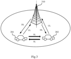
Fig.3 schematically shows another exemplary scenario of sidelink transmission and reception in NR. Similarly withFig.2 , inFig.3 , communication may be performed between twovehicles UE 100 shown inFig.1 may be thevehicle 201 and another user equipment communicating with theUE 100 may be thevehicle 202, and vice versa. For the purpose of avoiding redundancy, the same contents with that inFig.2 will not be described again. Different fromFig.2 , inFig.3 , there is further aBS 310 and the twovehicles BS 310. Uu communication may also be performed between each of the twovehicles BS 310 as shown by respective thin arrows noted as "DL" or "UL". -
Fig.3 shows an exemplary scenario in which sidelink transmission and reception and Uu communication coexists in NR. For example, the BWP assigned for sidelink transmission and reception in the carrier is used for sidelink only, that is to say, will not be shared with Uu communication. And, as described above, dynamic BWP switching is not supported for the sidelink transmission and reception. In addition, another BWP is assigned for Uu communication in the same carrier. For example, assuming thevehicle 201 as theUE 100, another BWP in the carrier may be assigned for the signaling between thevehicle 201 and theBS 310. Furthermore, more BWPs may be assigned for the signaling between thevehicle 201 and theBS 310, and dynamical BWP switching can still be supported within these BWPs assigned for Uu communication. - For example,
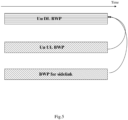
Fig.4 schematically shows an exemplary scenario of BWP assignment for both sidelink and Uu according to an embodiment of the present disclosure.Fig.4 shows an example of BWP assignment for both sidelink and Uu in a same uplink carrier in a Frequency Division Duplexing (FDD) case. As shown inFig.4 , two BWPs, i.e.Uplink BWP 1 andUplink BWP 2, are assigned for Uu communication and can be dynamically switched between each other, while one BWP, i.e. Sidelink BWP, is assigned for sidelink transmission and reception only.Uplink BWP 1,Uplink BWP 2 and Sidelink BWP are within the same carrier. Such carrier may correspond to a licensed carrier in which sidelink and Uu may coexist. - Here,
Uplink BWP 1 andUplink BWP 2 may also be considered as Uu BWPs which mean BWPs for eMBB traffic, URLLC traffic or the like. - With the above configuration in the present disclosure, Uu communication and sidelink communication have no impact to each other in the same carrier, meanwhile the sidelink receiver design is simplified and Uu operation in uplink such as dynamic BWP switching is not influenced.
- According to an embodiment of the present disclosure, in the
UE 100 as shown inFig.1 , the BWP and the other BWP are active in the carrier at the same time. - For example, as shown in
Fig.4 , during the first time duration T1, Sidelink BWP andUplink BWP 2 are active, and during the second time duration T2, Sidelink BWP andUplink BWP 1 are active. - Thus, in the present disclosure, more than one BWPs may be active in an uplink carrier at one time to support sidelink and Uu coexistence.
- According to an embodiment of the present disclosure, in the
UE 100 as shown inFig.1 , the BWP and the other BWP are associated with the same Downlink (DL) BWP in the carrier. - For example, in a FDD case, one UL BWP is paired with one DL BWP. In contrast, in the present disclosure, since multiple BWPs may be active at one time as described above, multiple BWPs may be associated with the same DL BWP in the carrier.
- For example,
Fig.5 schematically shows an exemplary scenario of the association between uplink/sidelink BWP and downlink BWP according to an embodiment of the present disclosure.Fig.5 corresponds to a FDD case. As shown inFig.5 , Uu UL BWP and BWP for sidelink are in the same uplink carrier and are both associated with the same Uu DL BWP as indicated by two curved arrows. For example, both UL grant for scheduling resources in Uu UL BWP and sidelink grant for scheduling sidelink resources may be transmitted in this Uu DL BWP. Here, sidelink transmission and reception may be gNB based scheduling transmission, for example. - Although
Fig.5 shows a FDD case, the present disclosure is not limited thereto.Fig.6 schematically shows another exemplary scenario of the association between uplink/sidelink BWP and downlink BWP according to an embodiment of the present disclosure.Fig.6 corresponds to a Time Division Duplexing (TDD) case. It is well known that a same BWP is operated for both UL and DL in a TDD case. For example, as shown inFig.6 , Uu BWP and sidelink BWP are in a same carrier. Uu BWP is assigned for both UL and DL transmission, and UL and DL uses Uu BWP in a time division manner. For example, there may be a gap between the time duration for DL and the time duration for UL, as shown by box filled with points and noted with "GAP" inFig.6 . In this case, both sidelink BWP and Uu UL BWP (i.e. UL in Uu BWP) are associated with the same Uu DL BWP (i.e. DL in Uu BWP) as indicated by the two curved arrows. - Similarly with the FDD case shown in
Fig.5 , in the TDD case, both UL grant for scheduling resources in Uu UL BWP and sidelink grant for scheduling sidelink resources may be transmitted in the Uu DL BWP. Here, sidelink transmission and reception may be gNB based scheduling transmission, for example. - In addition, when Uu is switched to another BWP, sidelink BWP may also be associated to DL in that BWP.
- According to an embodiment of the present disclosure, in the
UE 100 as shown inFig.1 , a sidelink duration in a slot in the BWP is changed with a change of a slot format in the other BWP in a case of Time Division Duplexing (TDD). - For example, as shown in
Fig.6 , on Uu BWP, the ratio of DL duration to UL duration in a slot may be changed, that is, the UL duration T may be changed. Correspondingly, the duration of sidelink resource in the slot on sidelink BWP will be changed with the change of the UL duration so as to align with the UL duration. - According to an embodiment of the present disclosure, in the
UE 100 as shown inFig.1 , whether to transmit a first channel in a BWP or receive a second channel on another BWP is decided based on priorities of the first channel and the second channel. - For example, this is on solving the half duplex issue. As described above, when sidelink communication and Uu communication coexist in a carrier, two BWP, respectively for sidelink and Uu, may be active at the same time. However, in this case, UE's reception or transmission may be restricted by the half duplex. According to the present disclosure, whether UE transmits one channel or receives another channel may be based on two channel's priority, for example, UE should drop the channel with lower priority. Here, the priority may be related with traffic priority, content priority and so on.
- For example, it is assumed that UE needs to receive a sidelink signal on one BWP in a carrier while transmitting a Uu signal on another BWP in the same carrier and that sidelink always has a higher priority. In this case, UE should drop the Uu signal and receive the sidelink signal. It is noted that this example is only for the purpose of illustration and the present disclosure is not limited thereto.
- According to an embodiment of the present disclosure, in the
UE 100 as shown inFig.1 , which one of a first channel on a BWP and a second channel on another BWP is to be transmitted is decided based on priorities of the first channel and the second channel when a Power Spectrum Density (PSD) difference between the first channel and the second channel is greater than a threshold. - For example, this is on solving the PSD difference issue. As described above, when sidelink communication and Uu communication coexist in a carrier, two BWP, respectively for sidelink and Uu, may be active at the same time. However, when UE needs to transmit one channel on a sidelink BWP and another channel on a Uu BWP at the same time, UE may meet a case that the PSD difference between the two channels is too large, for example, greater than a certain threshold. According to the present disclosure, which one of the two channels is to be transmitted may be based on two channel's priority, for example, UE should drop the channel with lower priority. Here, the priority may be related with traffic priority, content priority and so on.
- For example, it is assumed that UE needs to transmit a sidelink signal on one BWP in a carrier while transmitting a Uu signal on another BWP in the same carrier and that sidelink always has a higher priority. In this case, UE should drop the Uu signal and transmits the sidelink signal. It is noted that this example is only for the purpose of illustration and the present disclosure is not limited thereto.
- As described before, how to configure the resource for sidelink transmission and reception in NR is unclear so far. The concept of resource pool is adopted to implement resource configuration for sidlink communication in LTE V2X and the concept of BWP is adopted to implement resource configuration in NR. However, reusing both existing BWP and resource pool signaling seems to be a redundant (at least in frequency) and complicated signalling design on sidelink resource.
- In view of the above, according to an embodiment of the present disclosure, in the
UE 100 as shown inFig.1 , the BWP is configured by a BWP configuration signaling in which a bitmap indicating a time domain resource for the sidelink transmission and reception is included. - For example, first, in order to configure sidelink specific BWP, for example, sidelink specific fields in LTE resource pool may be added to BWP configuration signaling to indicate frequency and other information on NR sidelink (for example, taking Rel.14 field as the example). Basically, sidelink specific BWP may be configured as shown in
Fig.4 for example. Furthermore, a bitmap is added to the BWP configuration signaling to indicate the time domain resource on sidelink. In this way, resource pool configuration on sidelink is not needed. For example, the following codes show an example of the BWP configuration signaling.
- In the above exemplary codes, LTE resource pool related field is included in NR BWP configuration, as shown by bolded codes at the last several lines. It is noted that, the above exemplary codes are only for the purpose of illustration, the present disclosure is not limited thereto, and those skilled in the art may write different codes according specific requirements.
- In addition, when the
UE 100 is in coverage of a BS (for example, theBS 310 as shown inFig.3 ), the BWP configuration signaling may be received from the BS and the one BWP is configured by the BWP configuration signaling from the BS. Otherwise, when theUE 100 is out of coverage of a BS, that is, cannot receive the BWP configuration signaling from the BS, the one BWP may be preconfigured by the operator. For example, the operator may set the BWP configuration signaling and store it in the UE in advance when designing the UE. Thus, in this case, the UE does not need to receive the BWP configuration signaling from the BS. - With the above BWP configuration signaling, there is less impact on NR protocol in the present disclosure.
- Although the above embodiments are described taking BWP as the form of sidelink resource, the present disclosure is not limited thereto. For example, in an unlicensed carrier case as described above, one BWP may be equivalent to one carrier. In other words, in an unlicensed carrier case, there may be not BWP configuration any more. In this case, in the
UE 100 as shown inFig.1 , the BWP is configured by a resource pool configuration signaling in which BWP specific information is included. - For example, the principle of resource pool signalling in LTE V2X may be reused. NR BWP specific information like subcarrier spacing may be directly indicated in the resource pool configuration signaling. For example, the following codes show an example of the resource pool configuration signaling.

- In the above exemplary codes, NR BWP related field is included in the resource pool configuration, as shown by bolded codes at the last line. It is noted that, the above exemplary codes are only for the purpose of illustration, the present disclosure is not limited thereto, and those skilled in the art may write different codes according specific requirements. Thus, signaling design and UE behavior may be simplified.
- Similarly, when the
UE 100 is in coverage of a BS (for example, theBS 310 as shown inFig.3 ), the resource pool configuration signaling may be received from the BS. Otherwise, when theUE 100 is out of coverage of a BS, the one BWP may be preconfigured by the operator. For example, the operator may set the resource pool configuration signaling and store it in the UE in advance when designing the UE. Thus, in this case, the UE does not need to receive the resource pool configuration signaling from the BS. - The above exemplary design of the sidelink resource configuration signaling can be applied for both gNB scheduling based transmission mode and UE autonomous based transmission mode. For example, in case of gNB scheduling based transmission mode, BWP ID in sidelink grant can be interpreted as resource pool ID, or such field is not present. Furthermore, the exemplary design of the sidelink resource configuration signaling can be applied for both Uu and ITS carriers as well as both normal resource (for example, BWP or resource pool) and exceptional resource for sidelink operation. In addition, different sidelink resources may have different Cyclic Prefix (CP)/subcarrier spacing.
- In the above, the
UE 100 is described in detail with reference toFigs.1-6 . With theUE 100, since dynamic BWP switching is not supported for sidelink transmission and reception, the complexity of the receiver design may be reduced and the system performance may be improved. - In another embodiment of the present disclosure, there is provided a user equipment comprising: circuitry operative to determine a Bandwidth Part (BWP) assigned for sidelink transmission and reception in a carrier; and a transceiver operative to perform the sidelink transmission and reception on the determined BWP in the carrier, wherein more than one BWPs are active in the carrier at the same time.
- For example, compared with current NR supporting only on active BWP at one time in an uplink/downlink carrier, in the user equipment according to the present embodiment of the disclosure, more than one BWPs may be active in an uplink carrier at one time.
- It is noted that, different from the
UE 100 as shown inFig.1 , in the user equipment according the present embodiment, there is no limitation that dynamic BWP switching is not supported for the sidelink transmission and reception, that is to say, dynamic BWP switching may or may not be supported for the sidelink transmission and reception based on specific situations in the present embodiment. - According to an embodiment of the present disclosure, the more than one BWPs comprise the BWP assigned for sidelink transmission and reception in the carrier and another BWP assigned for transmission between the user equipment and a base station in the carrier.
- For example, one BWP dedicated for sidelink transmission and reception and another BWP dedicated for uplink communication may be active in an uplink carrier at one time, so that sidelink and Uu may coexist in an uplink carrier.
- In another embodiment of the present disclosure, there is provided a base station as shown in
Fig.7. Fig.7 illustrates a block diagram of a part of abase station 700 according to an embodiment of the present disclosure. As shown inFig.7 , theBS 700 may comprisecircuitry 710 and atransmitter 720. Thecircuitry 710 is operative to generate a Bandwidth Part (BWP) configuration signaling in which a bitmap indicating a time domain resource for sidelink transmission and reception is included. Thetransmitter 720 is operative to transmit the BWP configuration signaling to a user equipment. A BWP assigned for the sidelink transmission and reception in a carrier is determined by the user equipment based on the BWP configuration signaling, and dynamic BWP switching is not supported for the sidelink transmission and reception in the carrier. - For example,
BS 700 may beBS 310 as shown inFig.3 and the user equipment may be theUE 100 as shown inFig.1 and thevehicle 201 as shown inFig.3 . As described above, when theUE 100 in coverage of theBS 700, theUE 100 may receive the BWP configuration signaling from theBS 700 and determines the BWP assigned for the sidelink transmission and reception in the carrier based on the BWP configuration signaling. - According to an embodiment of the present disclosure, the BWP is used for the sidelink transmission and reception only, and another BWP is assigned for transmission between the user equipment and the base station in the carrier, and the
transmitter 720 is further operative to transmit a downlink signal on a Downlink (DL) BWP in the carrier to the user equipment. - For example, as described above with reference to
Fig.3 , thevehicle 201 may perform Uu communication with theBS 310 and perform sidelink transmission and reception with thevehicle 202. - With the
BS 700, since dynamic BWP switching is not supported for sidelink transmission and reception, the complexity of the receiver design may be reduced and the system performance may be improved. In addition, with the BWP configuration signaling, there is less impact on NR protocol in the present disclosure. -
Fig.8 illustrates a block diagram of details of auser equipment 800 according to an embodiment of the present disclosure. As shown inFig.8 , theUE 800 includes aencoder 801, amodulator 802, aresource mapper 803, aresource multiplexer 804, afirst signal processor 805, atransmitter 806, anantenna 807, areceiver 808, asecond signal processor 809, aresource demultiplexer 810, aresource demapper 811, ademodulator 812, adecoder 813 and acontrol circuitry 814. - For example, the
encoder 801 performs encoding processing on transmission data, and themodulator 802 performs modulation processing on post-encoding transmission data to generate a data symbol. Theresource mapper 803 maps the data symbol onto physical resources. For example, when the transmission data belongs to sidelink data to be transmitted to another UE, theresource mapper 803 maps the data symbol onto BWP assigned for sidelink transmission and reception. Theresource multiplexer 804 multiplexes the data symbol and possible control information and/or synchronization information. Thefirst signal processor 805 performs the signal processing on the multiplexed signal output from theresource multiplexer 804. Thetransmitter 806 transmits the processed sidelink signal to for example another UE via theantenna 807. - Here, the operations of the
encoder 801, themodulator 802, theresource mapper 803 and theresource multiplexer 804 are controlled by thecontrol circuitry 814. For example, thecontrol circuitry 814 may determine a BWP assigned for sidelink transmission and reception in a carrier. Theresource mapper 803 maps the sidelink data symbol onto the determined BWP and thetransmitter 806 transmits the sidelink signal on the determined BWP in the carrier to another UE. Thecontrol circuitry 814 may also controls dynamic switching for sidelink transmission and reception. In this disclosure, dynamic switching is not supported for the sidelink transmission and reception. - In addition, the
receiver 808 may receive a sidelink signal from another UE via theantenna 807. Thesecond signal processor 809 performs the signal processing on the sidelink signal received by thereceiver 808. Theresource demultiplexer 810 demultiplexes the processed sidelink signal into sidelink data and possible sidelink control information and/or synchronization information. Theresource demapper 811 demaps sidelink data symbol and possible sidelink control information and/or synchronization information from physical resources, for example, a BWP assigned for sidelink transmission and reception. Thedemodulatoer 812 performs demodulation processing on the sidelink data symbol and thedecoder 813 performs decoding processing on the demodulated sidelink data symbol to obtain the reception data. In addition, thedemodulatoer 812 may also performs demodulation processing on possible sidelink control information and/or synchronization information and thedecoder 813 performs decoding processing on the demodulated sidelink control information and/or synchronization information so as to output the sidelink control information and/or synchronization information to thecontrol circuitry 814 for controlling sidelink transmission and reception. - The above case may correspond to unlicensed carrier case, as described before, in which there is no Uu communication, however, the present disclosure is not limited thereto. In a licensed carrier case, the
UE 800 may transmit uplink signals to a base station (for example, theBS 310 shown inFig.3 ) through theencoder 801, themodulator 802, theresource mapper 803, theresource multiplexer 804, thefirst signal processor 805, thetransmitter 806, theantenna 807 and thecontrol circuitry 814. For example, thecontrol circuitry 814 may determine another BWP assigned for transmission between theUE 800 and the base station in the carrier and control theresource mapper 803 correspondingly. Thetransmitter 806 transmits the UL signal on the other BWP assigned for transmission between theUE 800 and the BS in the carrier to the BS via theantenna 807. - Furthermore, as described above, the
control circuitry 814 may determine more than one BWP assigned for transmission between theUE 800 and the base station in the carrier and control theresource mapper 803 correspondingly. Thetransmitter 806 transmits the UL signal on one of the more than one BWP assigned for transmission between theUE 800 and the BS in the carrier to the BS via theantenna 807. Dynamic BWP switching is supported within these BWPs. - Similarly, in a licensed carrier case, the
UE 800 may also receive downlink signals from a base station (for example, theBS 310 shown inFig.3 ) through theantenna 807, thereceiver 808, thesecond signal processor 809, theresource demultiplexer 810, theresource demapper 811, thedemodulator 812 and thedecoder 813. Since the principle of receiving DL signals from a BS is well known to those skilled in the art, detailed description will not be provided in order to avoid redundancy. - Note that, the
user equipment 800 shown inFig.8 may function asUE 100 as shown inFig.1 . Specifically, the combination of thetransmitter 806 and thereceiver 808 may correspond to thetransceiver 120. Thecircuitry 110 may include theencoder 801, themodulator 802, theresource mapper 803, theresource multiplexer 804, thefirst signal processor 805, thesecond signal processor 809, theresource demultiplexer 810, theresource demapper 811, thedemodulator 812, thedecoder 813 and thecontrol circuitry 814. Alternatively, one or more of these units may also be separated from thecircuitry 110 depending on specific requirements. -
Fig.9 schematically shows an example of a flowchart of communication among aBS 930 andUEs BS 930 may be theBS 700 as shown inFig.7 , and theUE 910 may be theUE 100 as shown inFig.1 or theUE 800 shown inFig.8 . - For example,
Fig.9 may correspond to a case that theUEs BS 930, which is similarly to that shown inFig.3 . That is to say, theUEs vehicles BS 930 may correspond to theBS 310. - As shown in
Fig.9 , at a step ST901, theUEs BS 930 may connect with each other in a connection procedure. The connection may be established by implementing known or future developed method whose details are omitted herein. - At a step ST902, the
UE 910 may transmit a sidelink scheduling request to theBS 930. Then, at a step ST903, theBS 930 decodes the sidelink scheduling request received from theUE 910 and generates sidelink control information. For example, as described above, the sidelink control information may include a BWP configuration signaling for configuring BWP dedicated for sidelink transmission and reception in a carrier. - At a step ST904, the
BS 930 transmits the generated sidelink control information to theUE 910. Then, at a step ST905, theUE 910 processes the sidelink control information received from theBS 930. For example, theUE 910 may determine the BWP dedicated for sidelink transmission and reception in a carrier based on the BWP configuration signaling received from theBS 930. - At a step ST906, the
UE 910 and theUE 920 may perform sidelink transmission and reception between each other on the BWP dedicated for sidelink transmission and reception in a carrier. - It is noted that, although not shown in
Fig.9 , theUE 910 and/or theUE 920 may further perform signal interaction with theBS 930 on BWPs assigned for uplink and downlink transmission. For example, theUE 910 may transmit a scheduling request for Uu to theBS 930 and receive control information for Uu from theBS 930. Since the uplink and downlink communication between a UE and a BS are well known to those skilled in the art, they will not be discussed herein. -
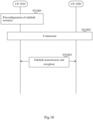
Fig.10 schematically shows an example of a flowchart of communication between aUE 1010 and aUE 1020 according to an embodiment of the present disclosure. For example, theUE 1010 may be theUE 100 as shown inFig.1 or theUE 800 shown inFig.8 . - For example,
Fig.10 may correspond to a case that theUEs Fig.2 . That is to say, theUEs vehicles Fig.2 respectively. - As described above, in a case of out of coverage of any BS, the
UE 1010 cannot receive any control information including sidelink resource configuration signaling from any BS. In this case, theUE 1010 should preconfigure sidelink resource before performing sidelink transmission and reception with another UE. As shown inFig.10 , at a step ST1001, theUE 1010 preconfigures sidelink resource. For example, the BWP dedicated for sidelink transmission and reception in a carrier may be preconfigured by the operator. For example, the operator may set the BWP configuration signaling and store it in the UE1010 in advance when designing the UE, and theUE 1010 may determine the BWP dedicated for sidelink transmission and reception in a carrier based on the BWP configuration signaling. - At a step ST1002, the
UE 1010 may connect with theUE 1020 in a connection procedure. The connection may be established by implementing known or future developed method whose details are omitted herein. - At a step ST1003, the
UE 1010 and theUE 1020 may perform sidelink transmission and reception between each other on the BWP dedicated for sidelink transmission and reception in a carrier. - Noted that, it is also possible that there is no step ST1002 here, since the connection procedure is not necessary during sidelink transmission and reception and two user equipments may also perform communication directly between each other without any connection procedure.
- In a further embodiment of the present disclosure, there is provided a wireless communication method for a user equipment as shown in
Fig.11. Fig.11 illustrates a flowchart of a wireless communication method 1100 for a user equipment according to an embodiment of the present disclosure. For example, the wireless communication method 1100 may be applied to theUE 100/800 as shown inFigs.1 and8 . - As shown in
Fig.11 , the wireless communication method 1100 starts at a step S1101 in which a BWP assigned for sidelink transmission and reception in a carrier is determined. Then, at a step S1102, the sidelink transmission and reception is performed on the determined BWP in the carrier. Dynamic BWP switching is not supported for the sidelink transmission and reception in the carrier. After the step S1102, the wireless communication method 1100 is ended. For example, another user equipment performing the sidelink transmission and reception with the user equipment may be thevehicle 202 as shown inFigs.2 and3 . - With the wireless communication method 1100, since dynamic BWP switching is not supported for sidelink transmission and reception, the complexity of the receiver design may be reduced and the system performance may be improved.
- Note that, the other technical features in the
user equipment 100 as described above can also be incorporated in the wireless communication method 1100 and will not be described here for avoiding redundancy. - In a further embodiment of the present disclosure, there is provided a wireless communication method for a base station as shown in
Fig.12. Fig.12 illustrates a flowchart of awireless communication method 1200 for a base station according to an embodiment of the present disclosure. For example, thewireless communication method 1200 may be applied to theBS 700 as shown inFig.7 . - As shown in
Fig.12 , thewireless communication method 1200 starts at a step S1201 in which a Bandwidth Part (BWP) configuration signaling in which a bitmap indicating a time domain resource for sidelink transmission and reception is included is generated. Then, at a step S1202, the BWP configuration signaling is transmitted to a user equipment. A BWP assigned for the sidelink transmission and reception in a carrier is determined by the user equipment based on the BWP configuration signaling. And, dynamic BWP switching is not supported for the sidelink transmission and reception in the carrier. After the step S1202, thewireless communication method 1200 is ended. For example, the user equipment may be theUE 100/800 as shown inFigs.1 and8 . - With the
wireless communication method 1200, since dynamic BWP switching is not supported for sidelink transmission and reception, the complexity of the receiver design may be reduced and the system performance may be improved. In addition, with the BWP configuration signaling, there is less impact on NR protocol in the present disclosure. - Note that, the other technical features in the
base station 700 as described above can also be incorporated in thewireless communication method 1200 and will not be described here for avoiding redundancy. - In a further embodiment of the present disclosure, there is provided a wireless communication method for a user equipment, comprising: determining a Bandwidth Part (BWP) assigned for sidelink transmission and reception in a carrier; and performing the sidelink transmission and reception on the determined BWP in the carrier, wherein more than one BWPs are active in the carrier at the same time.
- The present disclosure can be realized by software, hardware, or software in cooperation with hardware. Each functional block used in the description of each embodiment described above can be realized by an LSI as an integrated circuit, and each process described in the each embodiment may be controlled by LSI. They may be individually formed as chips, or one chip may be formed so as to include a part or all of the functional blocks. They may include a data input and output coupled thereto. The LSI here may be referred to as an IC, a system LSI, a super LSI, or an ultra LSI depending on a difference in the degree of integration. However, the technique of implementing an integrated circuit is not limited to the LSI and may be realized by using a dedicated circuit or a general-purpose processor. In addition, a FPGA (Field Programmable Gate Array) that can be programmed after the manufacture of the LSI or a reconfigurable processor in which the connections and the settings of circuits cells disposed inside the LSI can be reconfigured may be used.
- It is noted that the present disclosure intends to be variously changed or modified by those skilled in the art based on the description presented in the specification and known technologies without departing from the content and the scope of the present disclosure, and such changes and applications fall within the scope that claimed to be protected. Furthermore, in a range not departing from the content of the disclosure, the constituent elements of the above-described embodiments may be arbitrarily combined.
- Embodiments of the present disclosure can at least provide the following subject matters.
- (1). A user equipment, comprising:
- circuitry operative to determine a Bandwidth Part (BWP) assigned for sidelink transmission and reception in a carrier; and
- a transceiver operative to perform the sidelink transmission and reception on the determined BWP in the carrier,
- wherein dynamic BWP switching is not supported for the sidelink transmission and reception in the carrier.
- (2). The user equipment according to (1), wherein the BWP is used for the sidelink transmission and reception only, and wherein another BWP is assigned for transmission between the user equipment and a base station in the carrier.
- (3). The user equipment according to (2), wherein the BWP and the other BWP are active in the carrier at the same time.
- (4). The user equipment according to (2), wherein the BWP and the other BWP are associated with the same Downlink (DL) BWP in the carrier.
- (5). The user equipment according to (2), wherein a sidelink duration in a slot in the BWP is changed with a change of a slot format in the other BWP in a case of Time Division Duplexing (TDD).
- (6). The user equipment according to (2), wherein whether to transmit a first channel in a BWP or receive a second channel on another BWP is decided based on priorities of the first channel and the second channel.
- (7). The user equipment according to (2), wherein which one of a first channel on a BWP and a second channel on another BWP is to be transmitted is decided based on priorities of the first channel and the second channel when a Power Spectrum Density (PSD) difference between the first channel and the second channel is greater than a threshold.
- (8). The user equipment according to (1), wherein the BWP is configured by a BWP configuration signaling in which a bitmap indicating a time domain resource for the sidelink transmission and reception is included.
- (9). A wireless communication method for a user equipment, comprising:
- determining a Bandwidth Part (BWP) assigned for sidelink transmission and reception in a carrier; and
- performing the sidelink transmission and reception on the determined BWP in the carrier,
- wherein dynamic BWP switching is not supported for the sidelink transmission and reception in the carrier.
- (10). The wireless communication method according to (9), wherein the BWP is used for the sidelink transmission and reception only, and wherein another BWP is assigned for transmission between the user equipment and a base station in the carrier.
- (11). The wireless communication method according to (10), wherein the BWP and the other BWP are active in the carrier at the same time.
- (12). The wireless communication method according to (10), wherein the BWP and the other BWP are associated with the same Downlink (DL) BWP in the carrier.
- (13). The wireless communication method according to (10), wherein a sidelink duration in a slot in the BWP is changed with a change of a slot format in the other BWP in a case of Time Division Duplexing (TDD).
- (14). The wireless communication method according to (10), wherein whether to transmit a first channel in a BWP or receive a second channel on another BWP is decided based on priorities of the first channel and the second channel.
- (15). The wireless communication method according to (10), wherein which one of a first channel on a BWP and a second channel on another BWP is to be transmitted is decided based on priorities of the first channel and the second channel when a Power Spectrum Density (PSD) difference between the first channel and the second channel is greater than a threshold.
- (16). The wireless communication method according to (9), wherein the BWP is configured by a BWP configuration signaling in which a bitmap indicating a time domain resource for the sidelink transmission and reception is included.
- (17). A base station, comprising:
- circuitry operative to generate a Bandwidth Part (BWP) configuration signaling in which a bitmap indicating a time domain resource for sidelink transmission and reception is included;
- a transmitter operative to transmit the BWP configuration signaling to a user equipment,
- wherein a BWP assigned for the sidelink transmission and reception in a carrier is determined by the user equipment based on the BWP configuration signaling, and wherein
- dynamic BWP switching is not supported for the sidelink transmission and reception in the carrier.
- (18). The base station according to (17), wherein the BWP is used for the sidelink transmission and reception only, and wherein another BWP is assigned for transmission between the user equipment and a base station in the carrier, and wherein
the transmitter is further operative to transmit a downlink signal on a Downlink (DL) BWP in the carrier to the user equipment. - (19). The base station according to (18), wherein the BWP and the other BWP are active in the carrier at the same time.
- (20). The base station according to (18), wherein the BWP and the other BWP are associated with the same Downlink (DL) BWP in the carrier.
- (21). The base station according to (18), wherein a sidelink duration in a slot in the BWP is changed with a change of a slot format in the other BWP in a case of Time Division Duplexing (TDD).
- (22). The base station according to (18), wherein whether to transmit a first channel in a BWP or receive a second channel on another BWP is decided based on priorities of the first channel and the second channel.
- (23). The base station according to (18), wherein which one of a first channel on a BWP and a second channel on another BWP is to be transmitted is decided based on priorities of the first channel and the second channel when a Power Spectrum Density (PSD) difference between the first channel and the second channel is greater than a threshold.
- (24). A wireless communication method for a base station, comprising:
- generating a Bandwidth Part (BWP) configuration signaling in which a bitmap indicating a time domain resource for sidelink transmission and reception is included;
- transmiting the BWP configuration signaling to a user equipment,
- wherein a BWP assigned for the sidelink transmission and reception in a carrier is determined by the user equipment based on the BWP configuration signaling, and wherein
- dynamic BWP switching is not supported for the sidelink transmission and reception in the carrier.
- (25). The wireless communication method according to (24), wherein the BWP is used for the sidelink transmission and reception only, and wherein another BWP is assigned for transmission between the user equipment and a base station in the carrier, and wherein
the method further comprises transmitting a downlink signal on a Downlink (DL) BWP in the carrier to the user equipment. - (26). The wireless communication method according to (25), wherein the BWP and the other BWP are active in the carrier at the same time.
- (27). The wireless communication method according to (25), wherein the BWP and the other BWP are associated with the same Downlink (DL) BWP in the carrier.
- (28). The wireless communication method according to (25), wherein a sidelink duration in a slot in the BWP is changed with a change of a slot format in the other BWP in a case of Time Division Duplexing (TDD).
- (29). The wireless communication method according to (25), wherein whether to transmit a first channel in a BWP or receive a second channel on another BWP is decided based on priorities of the first channel and the second channel.
- (30). The wireless communication method according to (25), wherein which one of a first channel on a BWP and a second channel on another BWP is to be transmitted is decided based on priorities of the first channel and the second channel when a Power Spectrum Density (PSD) difference between the first channel and the second channel is greater than a threshold.
- (31). A user equipment, comprising:
- circuitry operative to determine a Bandwidth Part (BWP) assigned for sidelink transmission and reception in a carrier; and
- a transceiver operative to perform the sidelink transmission and reception on the determined BWP in the carrier,
- wherein more than one BWPs are active in the carrier at the same time.
- (32). The user equipment according to (31), wherein the more than one BWPs comprise the BWP assigned for the sidelink transmission and reception in the carrier and another BWP assigned for transmission between the user equipment and a base station in the carrier.
- (33). A wireless communication method for a user equipment, comprising:
- determining a Bandwidth Part (BWP) assigned for sidelink transmission and reception in a carrier; and
- performing the sidelink transmission and reception on the determined BWP in the carrier,
- wherein more than one BWPs are active in the carrier at the same time.
- (34). The wireless communication method according to (33), wherein the more than one BWPs comprise the BWP assigned for the sidelink transmission and reception in the carrier and another BWP assigned for transmission between the user equipment and a base station in the carrier.
- As such, the embodiments are limited only by the enclosed claims. Additional embodiments are summarized in the following clauses:
-
Clause 1. A user equipment, comprising:- circuitry operative to determine a Bandwidth Part (BWP) assigned for sidelink transmission and reception in a carrier; and
- a transceiver operative to perform the sidelink transmission and reception on the determined BWP in the carrier,
- wherein dynamic BWP switching is not supported for the sidelink transmission and reception in the carrier.
-
Clause 2. The user equipment according to clause1, wherein the BWP is used for the sidelink transmission and reception only, and wherein another BWP is assigned for transmission between the user equipment and a base station in the carrier. - Clause 3. The user equipment according to clause2, wherein the BWP and the other BWP are active in the carrier at the same time.
- Clause 4. The user equipment according to clause2, wherein the BWP and the other BWP are associated with the same Downlink (DL) BWP in the carrier.
- Clause 5. The user equipment according to
clause 2, wherein a sidelink duration in a slot in the BWP is changed with a change of a slot format in the other BWP in a case of Time Division Duplexing (TDD). - Clause 6. The user equipment according to
clause 2, wherein whether to transmit a first channel in a BWP or receive a second channel on another BWP is decided based on priorities of the first channel and the second channel. - Clause 7. The user equipment according toclause 2, wherein which one of a first channel on a BWP and a second channel on another BWP is to be transmitted is decided based on priorities of the first channel and the second channel when a Power Spectrum Density (PSD) difference between the first channel and the second channel is greater than a threshold.
- Clause 8. The user equipment according toclause 1, wherein the BWP is configured by a BWP configuration signaling in which a bitmap indicating a time domain resource for the sidelink transmission and reception is included.
- Clause 9. A wireless communication method for a user equipment, comprising:
- determining a Bandwidth Part (BWP) assigned for sidelink transmission and reception in a carrier; and
- performing the sidelink transmission and reception on the determined BWP in the carrier,
- wherein dynamic BWP switching is not supported for the sidelink transmission and reception in the carrier.
- Clause 10. The wireless communication method according to clause 9, wherein the BWP is used for the sidelink transmission and reception only, and wherein another BWP is assigned for transmission between the user equipment and a base station in the carrier.
- Clause 11. The wireless communication method according to clause 10, wherein the BWP and the other BWP are active in the carrier at the same time.
- Clause 12. The wireless communication method according to clause 10, wherein whether to transmit a first channel in a BWP or receive a second channel on another BWP is decided based on priorities of the first channel and the second channel.
- Clause 13. The wireless communication method according to clause 10, wherein which one of a first channel on a BWP and a second channel on another BWP is to be transmitted is decided based on priorities of the first channel and the second channel when a Power Spectrum Density (PSD) difference between the first channel and the second channel is greater than a threshold.
- Clause 14. The wireless communication method according to clause 9, wherein the BWP is configured by a BWP configuration signaling in which a bitmap indicating a time domain resource for the sidelink transmission and reception is included.
- Clause 15. A base station, comprising:
- circuitry operative to generate a Bandwidth Part (BWP) configuration signaling in which a bitmap indicating a time domain resource for sidelink transmission and reception is included;
- a transmitter operative to transmit the BWP configuration signaling to a user equipment,
- wherein a BWP assigned for the sidelink transmission and reception in a carrier is determined by the user equipment based on the BWP configuration signaling, and wherein
- dynamic BWP switching is not supported for the sidelink transmission and reception in the carrier.
- Clause 16. A wireless communication method for a base station, comprising:
- generating a Bandwidth Part (BWP) configuration signaling in which a bitmap indicating a time domain resource for sidelink transmission and reception is included;
- transmiting the BWP configuration signaling to a user equipment,
- wherein a BWP assigned for the sidelink transmission and reception in a carrier is determined by the user equipment based on the BWP configuration signaling, and wherein
- dynamic BWP switching is not supported for the sidelink transmission and reception in the carrier.
Claims (12)
- A base station, comprising:circuitry, which, in operation, assigns a first Bandwidth Part (BWP) for sidelink communication in a carrier to a user equipment, and assigns a second BWP assigned for a communication between the user equipment and the base station in the carrier to the user equipment; anda transceiver, which, in operation, performs the communication with the user equipment on the determined second BWP, and transmits a BWP configuration indicating the assigned first BWP,wherein the second BWP is a BWP that is dynamically switched among a plurality of second BWPs assigned for the communication between the user equipment and the base station in the carrier, and the first BWP is a BWP that is not dynamically switched.
- The base station according to claim 1, wherein the first BWP and the second BWP are active in the carrier at the same time.
- The base station according to claim 1, wherein a sidelink duration in a slot in the first BWP is changed according to a change of a slot format in the second BWP in a case of Time Division Duplexing (TDD).
- The base station according to claim 1, wherein whether the user equipment performs the sidelink communication on the assigned first BWP or performs the communication between the user equipment and the base station on the assigned second BWP is based on priorities.
- The base station according to claim 1, wherein the transceiver, in operation, transmits an indication for the dynamic BWP switching via a downlink control information (DCI).
- The base station according to claim 1, wherein the BWP configuration includes a bitmap indicating a time domain resource for the sidelink communication.
- A communication method, comprising:assigning a first Bandwidth Part (BWP) for sidelink communication in a carrier to a user equipment;assigning a second BWP assigned for a communication between the user equipment and a base station in the carrier to the user equipment;performing the communication between the base station and the user equipment on the determined second BWP; andtransmitting a BWP configuration indicating the assigned first BWP from the base station to the user equipment,wherein the second BWP is a BWP that is dynamically switched among a plurality of second BWPs assigned for the communication between the user equipment and the base station in the carrier, and the first BWP is a BWP that is not dynamically switched.
- The communication method according to claim 7, wherein the first BWP and the second BWP are active in the carrier at the same time.
- The communication method according to claim 7, wherein a sidelink duration in a slot in the first BWP is changed according to a change of a slot format in the second BWP in a case of Time Division Duplexing (TDD).
- The communication method according to claim 7, wherein whether the user equipment performs the sidelink communication on the assigned first BWP or performs the communication between the user equipment and the base station on the assigned second BWP is based on priorities.
- The communication method according to claim 7, comprising transmitting an indication for the dynamic BWP switching via a downlink control information (DCI).
- The communication method according to claim 7, wherein the BWP configuration includes a bitmap indicating a time domain resource for the sidelink communication.
Priority Applications (1)
| Application Number | Priority Date | Filing Date | Title |
|---|---|---|---|
| EP25175137.6A EP4576922A3 (en) | 2018-06-12 | 2018-06-12 | User equipment, base station and wireless communication method |
Applications Claiming Priority (3)
| Application Number | Priority Date | Filing Date | Title |
|---|---|---|---|
| PCT/CN2018/090737 WO2019237236A1 (en) | 2018-06-12 | 2018-06-12 | User equipment, base station and wireless communication method |
| EP18922789.5A EP3808145B1 (en) | 2018-06-12 | 2018-06-12 | User equipment, base station and wireless communication method |
| EP25175137.6A EP4576922A3 (en) | 2018-06-12 | 2018-06-12 | User equipment, base station and wireless communication method |
Related Parent Applications (2)
| Application Number | Title | Priority Date | Filing Date |
|---|---|---|---|
| EP18922789.5A Division EP3808145B1 (en) | 2018-06-12 | 2018-06-12 | User equipment, base station and wireless communication method |
| EP18922789.5A Division-Into EP3808145B1 (en) | 2018-06-12 | 2018-06-12 | User equipment, base station and wireless communication method |
Publications (2)
| Publication Number | Publication Date |
|---|---|
| EP4576922A2 true EP4576922A2 (en) | 2025-06-25 |
| EP4576922A3 EP4576922A3 (en) | 2025-08-13 |
Family
ID=68841700
Family Applications (2)
| Application Number | Title | Priority Date | Filing Date |
|---|---|---|---|
| EP25175137.6A Pending EP4576922A3 (en) | 2018-06-12 | 2018-06-12 | User equipment, base station and wireless communication method |
| EP18922789.5A Active EP3808145B1 (en) | 2018-06-12 | 2018-06-12 | User equipment, base station and wireless communication method |
Family Applications After (1)
| Application Number | Title | Priority Date | Filing Date |
|---|---|---|---|
| EP18922789.5A Active EP3808145B1 (en) | 2018-06-12 | 2018-06-12 | User equipment, base station and wireless communication method |
Country Status (11)
| Country | Link |
|---|---|
| US (3) | US11882544B2 (en) |
| EP (2) | EP4576922A3 (en) |
| JP (1) | JP7090739B2 (en) |
| KR (1) | KR102746182B1 (en) |
| CN (1) | CN112219434B (en) |
| BR (1) | BR112020023099A2 (en) |
| ES (1) | ES3039938T3 (en) |
| MX (1) | MX2020012375A (en) |
| RU (1) | RU2765301C1 (en) |
| SG (1) | SG11202011608RA (en) |
| WO (1) | WO2019237236A1 (en) |
Families Citing this family (22)
| Publication number | Priority date | Publication date | Assignee | Title |
|---|---|---|---|---|
| WO2020000176A1 (en) * | 2018-06-26 | 2020-01-02 | 北京小米移动软件有限公司 | Bwp switching method and device, and storage medium |
| US11917595B2 (en) * | 2018-07-03 | 2024-02-27 | Ntt Docomo, Inc. | Communication device and base station |
| US11595858B2 (en) * | 2018-08-08 | 2023-02-28 | Lg Electronics Inc. | Method and apparatus for performing resource reservation in NR V2X |
| CN115086913B (en) * | 2018-09-04 | 2024-07-12 | 上海朗帛通信技术有限公司 | A method and device used in a node for wireless communication |
| CN112640525A (en) * | 2018-09-13 | 2021-04-09 | Oppo广东移动通信有限公司 | Method and device for transmitting side link information, terminal device and network device |
| US11832240B2 (en) * | 2018-09-26 | 2023-11-28 | Beijing Xiaomi Mobile Software Co., Ltd. | Method and device for sidelink communication |
| CN112771964B (en) * | 2018-09-27 | 2024-05-07 | 夏普株式会社 | Bandwidth Partial Configuration for V2X Communication |
| CN111132327A (en) * | 2018-11-01 | 2020-05-08 | 华为技术有限公司 | Resource allocation method and device |
| CN111148237B (en) * | 2018-11-02 | 2022-12-30 | 华为技术有限公司 | Communication method and device |
| WO2020087512A1 (en) * | 2018-11-02 | 2020-05-07 | Lenovo (Beijing) Limited | Resource pool assignment |
| JP7176572B2 (en) * | 2018-11-07 | 2022-11-22 | 富士通株式会社 | Communication device, wireless communication system and resource selection method |
| EP3909372A4 (en) * | 2019-01-09 | 2022-08-24 | Sharp Kabushiki Kaisha | USER EQUIPMENT, BASE STATIONS AND METHODS FOR PHYSICAL SIDE LINK (SL) CONTROL CHANNEL MONITORING |
| US11991723B2 (en) * | 2019-01-11 | 2024-05-21 | Lg Electronics Inc. | Method and apparatus for performing BWP-based sidelink communication in NR V2X |
| CN111436089B (en) * | 2019-01-11 | 2021-08-20 | 华为技术有限公司 | Method and apparatus for communication |
| US11277250B2 (en) * | 2019-04-10 | 2022-03-15 | Hyundai Motor Company | Method and apparatus for reconfiguring bandwidth part for groupcase in sidelink communication |
| US11445491B2 (en) * | 2019-07-25 | 2022-09-13 | Qualcomm Incorporated | Reduced capability/complexity NR bandwidth part configuration |
| CN113993215B (en) | 2020-02-11 | 2023-08-04 | Oppo广东移动通信有限公司 | Time domain resource determining method and device and terminal equipment |
| EP4284115B1 (en) | 2020-04-08 | 2026-02-04 | Guangdong Oppo Mobile Telecommunications Corp., Ltd. | Time-domain resource determination method and apparatus |
| CN115669154B (en) * | 2020-08-07 | 2025-08-19 | Oppo广东移动通信有限公司 | Signal receiving method, signal transmitting method, terminal device and storage medium |
| US12022413B2 (en) * | 2020-08-27 | 2024-06-25 | Qualcomm Incorporated | Receiver timing adjustment |
| CN115085837B (en) * | 2021-03-12 | 2023-09-26 | 展讯通信(上海)有限公司 | Transmission method and device, storage medium, terminal |
| CN115550889B (en) * | 2021-06-29 | 2024-09-20 | 维沃移动通信有限公司 | Transmission method, device, equipment and medium |
Family Cites Families (23)
| Publication number | Priority date | Publication date | Assignee | Title |
|---|---|---|---|---|
| US20100195586A1 (en) * | 2009-02-05 | 2010-08-05 | Infineon Technologies Ag | Multiband-operation in wireless communication systems |
| EP2443851B1 (en) * | 2009-06-17 | 2018-01-17 | Telefonaktiebolaget LM Ericsson (publ) | Scheduling data transmissions between a mobile terminal and a base station in a wireless communications network |
| US9185690B2 (en) * | 2012-02-29 | 2015-11-10 | Sharp Kabushiki Kaisha | Allocating and determining resources for a device-to-device link |
| CN105099634B (en) * | 2014-05-09 | 2019-05-07 | 中兴通讯股份有限公司 | Dynamic resource allocation method and device, base station, and terminal |
| EP3157189B1 (en) * | 2014-06-16 | 2019-12-25 | LG Electronics Inc. | Method and apparatus for transmitting and receiving signal of device to device terminal in wireless communication system |
| RU2653495C1 (en) * | 2014-09-25 | 2018-05-10 | Телефонактиеболагет Лм Эрикссон (Пабл) | Method and device for improved reference signal in an upperlink in listen-before-talk systems |
| CN106304351A (en) * | 2015-05-27 | 2017-01-04 | 中兴通讯股份有限公司 | A kind of method and apparatus of resource distribution |
| KR102282754B1 (en) * | 2015-07-06 | 2021-07-27 | 후아웨이 테크놀러지 컴퍼니 리미티드 | Data transmission method, wireless network device and communication system |
| CN107371182A (en) * | 2016-05-13 | 2017-11-21 | 展讯通信(上海)有限公司 | User equipment and its data transmission method |
| US10749644B2 (en) * | 2016-08-12 | 2020-08-18 | Huawei Technologies Co., Ltd. | System and method for efficient bandwidth utilization |
| US10506596B2 (en) * | 2016-10-28 | 2019-12-10 | Qualcomm Incorporated | Coexistence of interleaved and contiguous uplink transmissions |
| SG11201903298PA (en) * | 2016-11-01 | 2019-05-30 | Lg Electronics Inc | Method and apparatus for configuring subband aggregation in nr carrier in wireless communication system |
| EP3535905A1 (en) * | 2016-11-03 | 2019-09-11 | Telefonaktiebolaget LM Ericsson (PUBL) | Uplink transmission bandwidth control and support |
| EP3535938B1 (en) * | 2016-11-03 | 2021-09-22 | Panasonic Intellectual Property Corporation of America | User equipment for wireless communication |
| CN109906653A (en) * | 2016-11-04 | 2019-06-18 | Lg电子株式会社 | The communication means of the frequency band of base station and the device using this method are used in a wireless communication system |
| US10728927B2 (en) * | 2016-11-11 | 2020-07-28 | FG Innovation Company Limited | Data packet delivery in RRC inactive state |
| MX393398B (en) * | 2016-11-25 | 2025-03-24 | Lg Electronics Inc | METHOD AND APPARATUS FOR DESIGNING A TRANSMISSION CHANNEL FOR NR IN A WIRELESS COMMUNICATION SYSTEM. |
| RU2734779C1 (en) * | 2016-12-23 | 2020-10-23 | Гуандун Оппо Мобайл Телекоммьюникейшнс Корп., Лтд. | Data transmission method and device |
| US10986610B2 (en) * | 2016-12-29 | 2021-04-20 | Lg Electronics Inc. | Method for transmitting and receiving signal in wireless communication system and apparatus therefor |
| US10660091B2 (en) * | 2017-08-10 | 2020-05-19 | Asustek Computer Inc. | Method and apparatus for handling SFI (slot format information) collision in a wireless communication system |
| WO2019090767A1 (en) * | 2017-11-13 | 2019-05-16 | Telefonaktiebolaget Lm Ericsson (Publ) | Switching of bandwidth parts in wireless communication network |
| CN117354096A (en) * | 2018-04-04 | 2024-01-05 | 三菱电机株式会社 | Communication systems, base stations and terminal devices |
| CN110392431B (en) * | 2018-04-19 | 2024-07-30 | 中兴通讯股份有限公司 | A method, device and system for implementing edge link resource configuration |
-
2018
- 2018-06-12 EP EP25175137.6A patent/EP4576922A3/en active Pending
- 2018-06-12 MX MX2020012375A patent/MX2020012375A/en unknown
- 2018-06-12 CN CN201880094281.8A patent/CN112219434B/en active Active
- 2018-06-12 BR BR112020023099-5A patent/BR112020023099A2/en unknown
- 2018-06-12 KR KR1020207034263A patent/KR102746182B1/en active Active
- 2018-06-12 SG SG11202011608RA patent/SG11202011608RA/en unknown
- 2018-06-12 WO PCT/CN2018/090737 patent/WO2019237236A1/en not_active Ceased
- 2018-06-12 US US17/056,641 patent/US11882544B2/en active Active
- 2018-06-12 EP EP18922789.5A patent/EP3808145B1/en active Active
- 2018-06-12 JP JP2020557936A patent/JP7090739B2/en active Active
- 2018-06-12 RU RU2020139703A patent/RU2765301C1/en active
- 2018-06-12 ES ES18922789T patent/ES3039938T3/en active Active
-
2023
- 2023-12-11 US US18/535,910 patent/US12133200B2/en active Active
-
2024
- 2024-10-02 US US18/904,735 patent/US12477520B2/en active Active
Also Published As
| Publication number | Publication date |
|---|---|
| BR112020023099A2 (en) | 2021-02-02 |
| US20250024431A1 (en) | 2025-01-16 |
| EP4576922A3 (en) | 2025-08-13 |
| KR20210020000A (en) | 2021-02-23 |
| US20210352623A1 (en) | 2021-11-11 |
| KR102746182B1 (en) | 2024-12-23 |
| RU2765301C1 (en) | 2022-01-28 |
| CN112219434A (en) | 2021-01-12 |
| SG11202011608RA (en) | 2020-12-30 |
| US12133200B2 (en) | 2024-10-29 |
| ES3039938T3 (en) | 2025-10-27 |
| JP7090739B2 (en) | 2022-06-24 |
| US12477520B2 (en) | 2025-11-18 |
| CN112219434B (en) | 2024-06-28 |
| MX2020012375A (en) | 2021-02-09 |
| US11882544B2 (en) | 2024-01-23 |
| US20240129899A1 (en) | 2024-04-18 |
| WO2019237236A1 (en) | 2019-12-19 |
| JP2021530880A (en) | 2021-11-11 |
| EP3808145C0 (en) | 2025-08-20 |
| EP3808145A1 (en) | 2021-04-21 |
| EP3808145A4 (en) | 2021-06-23 |
| EP3808145B1 (en) | 2025-08-20 |
Similar Documents
| Publication | Publication Date | Title |
|---|---|---|
| EP3808145B1 (en) | User equipment, base station and wireless communication method | |
| US12507226B2 (en) | Apparatus and method in wireless communication system, and computer-readable storage medium | |
| KR102564327B1 (en) | Communication devices and terminal devices | |
| CN112953691B (en) | Electronic device and wireless communication method in wireless communication system | |
| EP3667985A1 (en) | Apparatus and method in wireless communication system and computer readable storage medium | |
| TW201642636A (en) | Radio access technology for transmission design | |
| EP4221064A2 (en) | User equipment, base station and wireless communication method | |
| CN119895775A (en) | User equipment and base station involving time division communication | |
| US10820309B2 (en) | Communications in a wireless system | |
| JP7265670B2 (en) | User equipment, wireless communication method and integrated circuit | |
| KR102199873B1 (en) | Wireless communication method and apparatus | |
| US20250233721A1 (en) | Method for wireless communication, electronic device and computer-readable storage medium | |
| US20250233720A1 (en) | Method for wireless communication, electronic device and computer-readable storage medium | |
| US20250227682A1 (en) | Terminal, base station and communication method |
Legal Events
| Date | Code | Title | Description |
|---|---|---|---|
| PUAI | Public reference made under article 153(3) epc to a published international application that has entered the european phase |
Free format text: ORIGINAL CODE: 0009012 |
|
| STAA | Information on the status of an ep patent application or granted ep patent |
Free format text: STATUS: REQUEST FOR EXAMINATION WAS MADE |
|
| 17P | Request for examination filed |
Effective date: 20250508 |
|
| AC | Divisional application: reference to earlier application |
Ref document number: 3808145 Country of ref document: EP Kind code of ref document: P |
|
| AK | Designated contracting states |
Kind code of ref document: A2 Designated state(s): AL AT BE BG CH CY CZ DE DK EE ES FI FR GB GR HR HU IE IS IT LI LT LU LV MC MK MT NL NO PL PT RO RS SE SI SK SM TR |
|
| PUAL | Search report despatched |
Free format text: ORIGINAL CODE: 0009013 |
|
| AK | Designated contracting states |
Kind code of ref document: A3 Designated state(s): AL AT BE BG CH CY CZ DE DK EE ES FI FR GB GR HR HU IE IS IT LI LT LU LV MC MK MT NL NO PL PT RO RS SE SI SK SM TR |
|
| RIC1 | Information provided on ipc code assigned before grant |
Ipc: H04W 76/14 20180101AFI20250704BHEP Ipc: H04W 72/0453 20230101ALI20250704BHEP |
|
| GRAP | Despatch of communication of intention to grant a patent |
Free format text: ORIGINAL CODE: EPIDOSNIGR1 |
|
| STAA | Information on the status of an ep patent application or granted ep patent |
Free format text: STATUS: GRANT OF PATENT IS INTENDED |