EP4576511A1 - Electrical connection, electrical machine system comprising such an electrical connection and method for fixing busbars to a support - Google Patents
Electrical connection, electrical machine system comprising such an electrical connection and method for fixing busbars to a support Download PDFInfo
- Publication number
- EP4576511A1 EP4576511A1 EP24218849.8A EP24218849A EP4576511A1 EP 4576511 A1 EP4576511 A1 EP 4576511A1 EP 24218849 A EP24218849 A EP 24218849A EP 4576511 A1 EP4576511 A1 EP 4576511A1
- Authority
- EP
- European Patent Office
- Prior art keywords
- fixation
- electrical connection
- support
- busbars
- groove
- Prior art date
- Legal status (The legal status is an assumption and is not a legal conclusion. Google has not performed a legal analysis and makes no representation as to the accuracy of the status listed.)
- Pending
Links
Images



Classifications
-
- H—ELECTRICITY
- H02—GENERATION; CONVERSION OR DISTRIBUTION OF ELECTRIC POWER
- H02K—DYNAMO-ELECTRIC MACHINES
- H02K3/00—Details of windings
- H02K3/46—Fastening of windings on the stator or rotor structure
- H02K3/50—Fastening of winding heads, equalising connectors, or connections thereto
-
- H—ELECTRICITY
- H02—GENERATION; CONVERSION OR DISTRIBUTION OF ELECTRIC POWER
- H02K—DYNAMO-ELECTRIC MACHINES
- H02K5/00—Casings; Enclosures; Supports
- H02K5/04—Casings or enclosures characterised by the shape, form or construction thereof
- H02K5/22—Auxiliary parts of casings not covered by groups H02K5/06-H02K5/20, e.g. shaped to form connection boxes or terminal boxes
- H02K5/225—Terminal boxes or connection arrangements
-
- H—ELECTRICITY
- H02—GENERATION; CONVERSION OR DISTRIBUTION OF ELECTRIC POWER
- H02G—INSTALLATION OF ELECTRIC CABLES OR LINES, OR OF COMBINED OPTICAL AND ELECTRIC CABLES OR LINES
- H02G5/00—Installations of bus-bars
- H02G5/02—Open installations
- H02G5/025—Supporting structures
-
- H—ELECTRICITY
- H02—GENERATION; CONVERSION OR DISTRIBUTION OF ELECTRIC POWER
- H02K—DYNAMO-ELECTRIC MACHINES
- H02K2203/00—Specific aspects not provided for in the other groups of this subclass relating to the windings
- H02K2203/09—Machines characterised by wiring elements other than wires, e.g. bus rings, for connecting the winding terminations
Definitions
- the present invention relates to an electrical connection, an electrical machine system comprising such an electrical connection and a method for fixing busbars to a support.
- a mobility device is for example a motorized land vehicle, a train, an aircraft or even a drone.
- a motorized land vehicle is for example a motor vehicle, a motorcycle, a motorized bicycle or a motorized wheelchair.
- busbars for connecting an inverter to phases of an electrical machine. Due to tolerances, the connection points of the inverter and/or the connection points of the electrical machine may be slightly misplaced. The busbars, which are rigid electrical conductors, are therefore bent to compensate.
- busbars are often over-molded together.
- the overmolding may crack because of the bending of the busbars.
- the invention aims to overcome at least part of the preceding problems.
- the invention relates to an electrical connection comprising:
- the invention may also include one or more of the following optional features, in any technically possible combination.
- the fixation hole has a periphery extending at least 0.5 mm from the fixation pin, all along the periphery.
- each fixation hole extends at most 1,5 mm from the fixation pin, and preferably at most 1mm from the fixation pin, all along the periphery.
- the support comprises two flexible tabs from which the fixation pins respectively projects.
- each tab extends parallel to the bottom of the groove.
- each tab is cut into the bottom of the groove.
- fixation pin projects perpendicular to the tab.
- the tabs are made of plastic.
- the support is made of plastic.
- At least one of the fixation holes are circular.
- the support comprises at least one positioning pin for positioning the support with respect to a housing of the electrical machine.
- the invention also relates to an electrical machine system comprising:
- the invention also relates to a method for fixing, to a support, busbars designed for connecting an inverter to an electrical machine, comprising inserting the busbars into respective grooves of the support and, for each groove, inserting two fixation pins projecting from a bottom of the groove respectively in two fixation holes of the busbar, wherein each fixation hole is larger than the fixation pin received so that the fixation hole has a periphery extending at least 0.5 mm from the fixation pin, all along the periphery.
- the method further comprises riveting the fixation pins in order to fix the busbars to the support.
- the method further comprises, for each busbar, connecting a first connection portion of the busbar to the inverter and a second connection portion of the busbar to the electrical machine, for example by screwing or welding.
- the electrical machine system 100 is for example designed to be used in a mobility device.
- the electrical machine system 100 first comprises an electrical machine 102 having several phases 104u, 104v, 104w.
- the electrical machine system 100 further comprises a DC voltage source 106, such as a battery.
- the electrical machine system 100 further comprises an inverter 108 designed for providing phase voltages U, V, W from the DC voltage source 106.
- the electrical machine system 100 further comprises an electrical connection 110.
- the electrical connection 110 first comprises several busbars 202 U , 202 V , 202 W designed for connecting the inverter 108 to the phases 104 U-W of the electrical machine 102, in order to respectively convey the phase voltages U, V, W from the inverter 108 to respectively the phases 104 U-W of the electrical machine 102.
- Each busbar 202 U-W is a rigid strip, for example bent, made of electrical conductive material such as copper.
- each busbar 202 U-W comprises a first connection portion 204 U , 204 V , 204 W designed to be connected to the inverter 108 and a second connection portion 206 U , 206 V , 206 W designed to be connected to the respective phase 104 U-W of the electrical machine 102.
- the connection to the inverter 108 and/or the phases 104 U-W is for example realized by screwing or welding.
- the connection portion 204 U-W , 206 U-W comprises for example a screwing hole 208 U , 208 V , 208 W , 210 U , 210 V , 210 W .
- Each busbar 202 U-W further comprises two fixation holes 212 U , 212 V , 212 W , 214 U , 214 V , 214 W , for example located between the two connection portions 204 U-W , 206 U-W along the strip.
- the electrical connection 110 further comprises a support 216 designed for supporting the busbars 202 U-W .
- the support 216 comprises grooves 218U, 218V, 218W designed for respectively receiving the busbars 202 U-W .
- the support 216 further comprises, for each groove 218u-w, two fixation pins 220 U , 220 V , 220 W , 222 U , 222 V , 222 W projecting from a bottom (not depicted in figure 2 ) of the groove 218 U-W , designed for being respectively received in the fixation holes 212 U-W , 214 U-W of the busbar 202 U-W received in the groove 218 U-W .
- the support 216 further comprises at least one positioning pin 224, 226 for positioning the support 216 with respect to a housing (not depicted) of the electrical machine 102.
- the support 216 is made of electrical non-conductive material, such as plastic.
- the support 216 comprises for example, for each groove 218 U-W , two flexible tabs 302, 304 from which the pins respectively projects, for instance perpendicularly to the tab 302, 304.
- each tab 302, 304 extends parallel to the bottom, associated with reference 306 in figure 3 , of the groove 218 U-W .
- each tab 302, 304 is cut into the bottom 306 of the groove 218 U-W .
- the tabs 304, 306 are preferably made of plastic.
- each fixation hole 212 U-W , 214 U-W is larger than the fixation pin 220 U-W , 222 U-W received so that the fixation hole 212 U-W , 214 U-W has a periphery extending, all along the periphery, at least 0,5 mm and at most 1 mm from the fixation pin 220 U-W , 222 U-W received.
- fixation holes are for example circular (fixation hole 214 U-W in the figures) and/or at least one of the fixation holes is oblong (fixation hole 212 U-W in the figures).
- the oblong fixation hole has then a first dimension d1 at least 20% longer than a second dimension d2 perpendicular to the first dimension d1.
- the circular fixation hole has a periphery extending at a distance d between 0,6 mm and 0,7 mm.
- fixation pins 220 U-W are designed to be riveted to fix the busbars 202 U-W to the support 216.
- a method 600 for fixing the busbars 202 U-W to the support 216 first comprises a step 602 of respectively inserting the busbars 202 U-W into the grooves 218 U-W of the support 216. During this step, for each groove 218u-w, the two fixation pins are respectively inserted into the two fixation holes 212 U-W .
- fixation pins 220u-w, 222 U-W are riveted in order to fix the busbars 202 U-W to the support 216.
- the first connection portion 204 U-W is connected to the inverter 108 and the second connection portion 206 U-W is connected to the electrical machine 102, for example by screwing or welding.
- the invention allows some movement, with respect to the support 116, of each busbar against the bottom 306 (in the X, Y directions in figure 3 ). Furthermore, the use of the flexible tabs 304, 306 allows some movement perpendicularly to the bottom 306 (in the Z direction in figure 3 ).
Landscapes
- Engineering & Computer Science (AREA)
- Power Engineering (AREA)
- Motor Or Generator Frames (AREA)
Abstract
The electrical connection (110) comprises: - several busbars (202U-W) designed for connecting an inverter to an electrical machine, each busbar (202U-W) having two fixation holes (212U-W, 214U-W); - a support (216) designed for supporting the busbars (202U-W), the support (216) comprising: • grooves (218U-W) designed for respectively receiving the busbars (202U-W), and • for each groove (218U-W), two fixation pins (220U-W, 222U-W) projecting from a bottom (306) of the groove (218U-W), designed for being respectively received in the fixation holes (212U-W, 214U-W) of the busbar (202U-W) received in the groove (218U-W) and for being riveted to fix the busbars (202U-W) to the support (216); wherein each fixation hole (212U-W, 214U-W) is larger than the fixation pin (220U-W, 222U-W) received.
Description
- The present invention relates to an electrical connection, an electrical machine system comprising such an electrical connection and a method for fixing busbars to a support.
- The invention may in particular be used in a mobility device. A mobility device is for example a motorized land vehicle, a train, an aircraft or even a drone. A motorized land vehicle is for example a motor vehicle, a motorcycle, a motorized bicycle or a motorized wheelchair.
- It is known to use busbars for connecting an inverter to phases of an electrical machine. Due to tolerances, the connection points of the inverter and/or the connection points of the electrical machine may be slightly misplaced. The busbars, which are rigid electrical conductors, are therefore bent to compensate.
- To insulate the busbars from the environment, the busbars are often over-molded together. However, the overmolding may crack because of the bending of the busbars.
- The invention aims to overcome at least part of the preceding problems.
- The invention relates to an electrical connection comprising:
- several busbars designed for connecting an inverter to an electrical machine, each busbar having two fixation holes;
- a support designed for supporting the busbars, the support comprising:
- grooves designed for respectively receiving the busbars, and
- for each groove, two fixation pins projecting from a bottom of the groove, designed for being respectively received in the fixation holes of the busbar received in the groove and for being riveted to fix the busbars to the support;
- The invention may also include one or more of the following optional features, in any technically possible combination.
- Optionally, the fixation hole has a periphery extending at least 0.5 mm from the fixation pin, all along the periphery.
- Optionally, the periphery of each fixation hole extends at most 1,5 mm from the fixation pin, and preferably at most 1mm from the fixation pin, all along the periphery.
- Also optionally, the support comprises two flexible tabs from which the fixation pins respectively projects.
- Also optionally, each tab extends parallel to the bottom of the groove.
- Also optionally, each tab is cut into the bottom of the groove.
- Also optionally, the fixation pin projects perpendicular to the tab.
- Also optionally, the tabs are made of plastic.
- Also optionally, the support is made of plastic.
- Also optionally, for each busbar, at least one of the fixation holes, for example both, are circular.
- Also optionally, for each busbar, at least one of the fixation holes is oblong, with a first dimension at least 20% longer than a second dimension perpendicular to the first dimension.
- Also optionally, the support comprises at least one positioning pin for positioning the support with respect to a housing of the electrical machine.
- The invention also relates to an electrical machine system comprising:
- an electrical machine having several phases;
- an inverter; and
- an electrical connection according to the invention.
- The invention also relates to a method for fixing, to a support, busbars designed for connecting an inverter to an electrical machine, comprising inserting the busbars into respective grooves of the support and, for each groove, inserting two fixation pins projecting from a bottom of the groove respectively in two fixation holes of the busbar, wherein each fixation hole is larger than the fixation pin received so that the fixation hole has a periphery extending at least 0.5 mm from the fixation pin, all along the periphery.
- Optionally, the method further comprises riveting the fixation pins in order to fix the busbars to the support.
- Also optionally, the method further comprises, for each busbar, connecting a first connection portion of the busbar to the inverter and a second connection portion of the busbar to the electrical machine, for example by screwing or welding.
- The invention will be better understood with the help of the description which follows, given solely by way of example and made with reference to the appended drawings in which:
-
figure 1 is schematic view of an electrical machine system in which the invention may be carried out, -
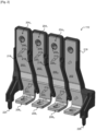
figure 2 is a three-dimensional view of an electrical connection according to the invention, used in the electrical machine system offigure 1 , -
figure 3 is a three-dimensional view of a portion of the electrical connection, -
figure 4 is a top view of fixation holes and pins, -
figure 5 is a three-dimensional view similar tofigure 2 , after the riveting of fixation pins, and -
figure 6 is a flow chart of a method for fixing busbars to a support. - Referring to
figure 1 , anelectrical machine system 100 in which the invention may be carried out, will now be described. Theelectrical machine system 100 is for example designed to be used in a mobility device. - The
electrical machine system 100 first comprises anelectrical machine 102 havingseveral phases - The
electrical machine system 100 further comprises aDC voltage source 106, such as a battery. - The
electrical machine system 100 further comprises aninverter 108 designed for providing phase voltages U, V, W from theDC voltage source 106. - The
electrical machine system 100 further comprises anelectrical connection 110. - Referring to
figure 2 , theelectrical connection 110 will now be described in more detail. - The
electrical connection 110 first comprisesseveral busbars inverter 108 to the phases 104U-W of theelectrical machine 102, in order to respectively convey the phase voltages U, V, W from theinverter 108 to respectively the phases 104U-W of theelectrical machine 102. Eachbusbar 202U-W is a rigid strip, for example bent, made of electrical conductive material such as copper. - In order to be connected, each
busbar 202U-W comprises a first connection portion 204U, 204V, 204W designed to be connected to theinverter 108 and asecond connection portion electrical machine 102. The connection to theinverter 108 and/or the phases 104U-W is for example realized by screwing or welding. In case of screwing, theconnection portion 204U-W, 206U-W comprises for example ascrewing hole - Each
busbar 202U-W further comprises twofixation holes connection portions 204U-W, 206U-W along the strip. - The
electrical connection 110 further comprises asupport 216 designed for supporting thebusbars 202U-W. Thesupport 216 comprises grooves 218U, 218V, 218W designed for respectively receiving thebusbars 202U-W. Thesupport 216 further comprises, for each groove 218u-w, twofixation pins figure 2 ) of thegroove 218U-W, designed for being respectively received in thefixation holes busbar 202U-W received in thegroove 218U-W. - For example, The
support 216 further comprises at least onepositioning pin support 216 with respect to a housing (not depicted) of theelectrical machine 102. - The
support 216 is made of electrical non-conductive material, such as plastic. - Referring to
figure 3 , thesupport 216 comprises for example, for eachgroove 218U-W, twoflexible tabs 302, 304 from which the pins respectively projects, for instance perpendicularly to thetab 302, 304. - Preferably, each
tab 302, 304 extends parallel to the bottom, associated withreference 306 infigure 3 , of thegroove 218U-W. For example, eachtab 302, 304 is cut into thebottom 306 of thegroove 218U-W. - In order to be flexible, the
tabs - Referring to
figure 4 , eachfixation hole fixation pin fixation hole fixation pin - For each
busbar 202U-W, at least one of the fixation holes is for example circular (fixation hole 214U-W in the figures) and/or at least one of the fixation holes is oblong (fixation hole 212U-W in the figures). The oblong fixation hole has then a first dimension d1 at least 20% longer than a second dimension d2 perpendicular to the first dimension d1. - The circular fixation hole has a periphery extending at a distance d between 0,6 mm and 0,7 mm.
- Referring to
figure 5 , the fixation pins 220U-W are designed to be riveted to fix thebusbars 202U-W to thesupport 216. - Referring to
figure 6 , amethod 600 for fixing thebusbars 202U-W to thesupport 216 first comprises astep 602 of respectively inserting thebusbars 202U-W into thegrooves 218U-W of thesupport 216. During this step, for each groove 218u-w, the two fixation pins are respectively inserted into the two fixation holes 212U-W. - During a
step 604, the fixation pins 220u-w, 222U-W are riveted in order to fix thebusbars 202U-W to thesupport 216. - During a
step 606, for eachbusbar 202U-W, the first connection portion 204U-W is connected to theinverter 108 and thesecond connection portion 206U-W is connected to theelectrical machine 102, for example by screwing or welding. - In conclusion, the invention allows some movement, with respect to the support 116, of each busbar against the bottom 306 (in the X, Y directions in
figure 3 ). Furthermore, the use of theflexible tabs figure 3 ). - It should also be noted that the invention is not limited to the embodiments described above. It will indeed appear to those skilled in the art that various modifications can be made to the embodiments described above, in light of the teaching which has just been disclosed to him.
- In the detailed presentation of the invention which is made previously, the terms used should not be interpreted as limiting the invention to the embodiments set out in the present description, but must be interpreted to include all the equivalents for which the prediction is within the reach of those skilled in the art by applying their general knowledge to the implementation of the teaching which has just been disclosed to them.
Claims (12)
- Electrical connection (110) comprising:- several busbars (202U-W) designed for connecting an inverter (108) to an electrical machine (102), each busbar (202U-W) having two fixation holes (212U-W, 214U-W);- a support (216) designed for supporting the busbars (202U-W), the support (216) comprising:wherein each fixation hole (212U-W, 214U-W) is larger than the fixation pin (220U-W, 222U-W) received.• grooves (218U-W) designed for respectively receiving the busbars (202U-W), and• for each groove (218U-W), two fixation pins (220U-W, 222U-W) projecting from a bottom (306) of the groove (218U-W), designed for being respectively received in the fixation holes (212U-W, 214U-W) of the busbar (202U-W) received in the groove (218U-W) and for being riveted to fix the busbars (202U-W) to the support (216);
- Electrical connection (110) according to claim 1, wherein the fixation hole (212U-W, 214U-W) has a periphery extending at least 0.5 mm from the fixation pin (220U-W, 222U-W), all along the periphery.
- Electrical connection (110) according to claim 1 or 2, wherein the periphery of each fixation hole (212U-W, 214U-W) extends at most 1,5 mm from the fixation pin (220U-W, 222U-W), and preferably at most 1mm from the fixation pin (220U-W, 222U-W), all along the periphery.
- Electrical connection (110) according to any of claims 1 to 3, wherein the support (216) comprises two flexible tabs (304, 306) from which the fixation pins (220U-W, 222U-W) respectively projects.
- Electrical connection (110) according to claim 3, wherein each tab (304, 306) extends parallel to the bottom (306) of the groove (218U-W).
- Electrical connection (110) according to claim 4 or 5, wherein each tab (304, 306) is cut into the bottom (306) of the groove (218U-W).
- Electrical connection (110) according to any of claims 4 to 6, wherein the fixation pin (220U-W, 222U-W) projects perpendicular to the tab (304, 306).
- Electrical connection (110) according to any of claims 4 to 7, wherein the tabs (304, 306) are made of plastic.
- Electrical connection (110) according to any of claims 1 to 8, wherein the support (216) is made of plastic.
- Electrical connection (110) according to any of claims 1 to 9, wherein, for each busbar (202U-W), at least one of the fixation holes (212U-W, 214U-W), for example both, are circular or oblong, with a first dimension (D1) at least 20% longer than a second dimension (D2) perpendicular to the first dimension (D1).
- Electrical connection (110) according to any of claims 1 to 10, wherein the support (216) comprises at least one positioning pin (224, 226) for positioning the support (216) with respect to a housing of the electrical machine (102).
- Electrical machine system (100) comprising:- an electrical machine (102) having several phases (104U-W);- an inverter (108); and- an electrical connection (110) according to any of claims 1 to 11.
Applications Claiming Priority (1)
| Application Number | Priority Date | Filing Date | Title |
|---|---|---|---|
| DE102023136116.3A DE102023136116A1 (en) | 2023-12-20 | 2023-12-20 | Electrical connection, electrical machine system comprising such an electrical connection, and method for fastening busbars to a support |
Publications (1)
| Publication Number | Publication Date |
|---|---|
| EP4576511A1 true EP4576511A1 (en) | 2025-06-25 |
Family
ID=93852929
Family Applications (1)
| Application Number | Title | Priority Date | Filing Date |
|---|---|---|---|
| EP24218849.8A Pending EP4576511A1 (en) | 2023-12-20 | 2024-12-10 | Electrical connection, electrical machine system comprising such an electrical connection and method for fixing busbars to a support |
Country Status (3)
| Country | Link |
|---|---|
| US (1) | US20250211057A1 (en) |
| EP (1) | EP4576511A1 (en) |
| DE (1) | DE102023136116A1 (en) |
Citations (4)
| Publication number | Priority date | Publication date | Assignee | Title |
|---|---|---|---|---|
| US20190006905A1 (en) * | 2016-01-08 | 2019-01-03 | Zf Friedrichshafen Ag | Stator For An Electrical Machine Having an Interconnection Device For Stator Coils, And Electrical Machine Having A Stator Of This Kind |
| US20210281138A1 (en) * | 2018-07-19 | 2021-09-09 | Sew-Eurodrive Gmbh & Co. Kg | Electric motor having an interconnection unit and method for manufacturing an electric motor having an interconnection unit |
| DE102021203954A1 (en) * | 2020-06-24 | 2021-12-30 | Robert Bosch Gesellschaft mit beschränkter Haftung | Stator of an electrical machine |
| US20220077606A1 (en) * | 2019-02-08 | 2022-03-10 | Gkn Automotive Limited | Connector assembly for inverter busbar and drive unit |
Family Cites Families (2)
| Publication number | Priority date | Publication date | Assignee | Title |
|---|---|---|---|---|
| JP6361451B2 (en) | 2014-10-16 | 2018-07-25 | 株式会社デンソー | Electrical device and method of manufacturing electrical device |
| JP7384861B2 (en) | 2021-06-28 | 2023-11-21 | 矢崎総業株式会社 | shield connector |
-
2023
- 2023-12-20 DE DE102023136116.3A patent/DE102023136116A1/en active Pending
-
2024
- 2024-12-10 EP EP24218849.8A patent/EP4576511A1/en active Pending
- 2024-12-19 US US18/987,800 patent/US20250211057A1/en active Pending
Patent Citations (4)
| Publication number | Priority date | Publication date | Assignee | Title |
|---|---|---|---|---|
| US20190006905A1 (en) * | 2016-01-08 | 2019-01-03 | Zf Friedrichshafen Ag | Stator For An Electrical Machine Having an Interconnection Device For Stator Coils, And Electrical Machine Having A Stator Of This Kind |
| US20210281138A1 (en) * | 2018-07-19 | 2021-09-09 | Sew-Eurodrive Gmbh & Co. Kg | Electric motor having an interconnection unit and method for manufacturing an electric motor having an interconnection unit |
| US20220077606A1 (en) * | 2019-02-08 | 2022-03-10 | Gkn Automotive Limited | Connector assembly for inverter busbar and drive unit |
| DE102021203954A1 (en) * | 2020-06-24 | 2021-12-30 | Robert Bosch Gesellschaft mit beschränkter Haftung | Stator of an electrical machine |
Also Published As
| Publication number | Publication date |
|---|---|
| US20250211057A1 (en) | 2025-06-26 |
| DE102023136116A1 (en) | 2025-06-26 |
Similar Documents
| Publication | Publication Date | Title |
|---|---|---|
| EP3637569B1 (en) | Large current circuit breaker plug-in installation | |
| JP5252316B2 (en) | Electrical connection device for flat conductors | |
| US9362653B2 (en) | Connector | |
| US10477717B2 (en) | Self-aligning busbar assembly | |
| US11143676B2 (en) | Element of an electric equipment casing, in particular comprising U-shaped magnetic parts | |
| CN101019279A (en) | Apparatus direct mounting connector | |
| CN105048682A (en) | Electric motor-driven compressor having an electrical terminal block assembly | |
| CN106028733A (en) | Structure for maintaining orientation of substrate with respect to casing | |
| JP2011113942A (en) | connector | |
| US20200091696A1 (en) | System for isolating power conductors using slidable insulating sheets | |
| CN102893475B (en) | Cable connection structure | |
| US11782076B2 (en) | Electrical device for receiving a magnetic field measurement sensor | |
| CN102301534B (en) | Terminals connecting structure | |
| CN113366739B (en) | Connector assembly, drive unit and electrical connection method | |
| EP2858229A1 (en) | Apparatus for Connecting a Shared DC Bus Link | |
| CN110800385B (en) | Voltage converter, method for manufacturing such a voltage converter, and components for forming a main module and a terminal block module of such a voltage converter | |
| CN109962628B (en) | Electrical equipment and housing components | |
| US20250211057A1 (en) | Electrical connection, electrical machine system comprising such an electrical connection and method for fixing busbars to a support | |
| CN103270651B (en) | Flexible device, system and method for mounting the system for electrically connecting electrical components and printed circuit boards together | |
| JP2011113945A (en) | Connection structure | |
| US20220163570A1 (en) | Electrical device for measuring a magnetic field in order to perform a current measurement | |
| BR102024026700A2 (en) | ELECTRICAL CONNECTION, ELECTRICAL MACHINE SYSTEM COMPRISING SUCH ELECTRICAL CONNECTION AND METHOD OF ATTACHING BUSBAR TO A SUPPORT | |
| JP5120636B2 (en) | Wiring device and wiring duct system | |
| US12257961B2 (en) | Clamp and wire harness | |
| CN110800384A (en) | Component assembly and method for manufacturing such an assembly |
Legal Events
| Date | Code | Title | Description |
|---|---|---|---|
| PUAI | Public reference made under article 153(3) epc to a published international application that has entered the european phase |
Free format text: ORIGINAL CODE: 0009012 |
|
| STAA | Information on the status of an ep patent application or granted ep patent |
Free format text: STATUS: EXAMINATION IS IN PROGRESS |
|
| 17P | Request for examination filed |
Effective date: 20241210 |
|
| AK | Designated contracting states |
Kind code of ref document: A1 Designated state(s): AL AT BE BG CH CY CZ DE DK EE ES FI FR GB GR HR HU IE IS IT LI LT LU LV MC ME MK MT NL NO PL PT RO RS SE SI SK SM TR |