EP4576507A1 - Rotating electric machine stator - Google Patents
Rotating electric machine stator Download PDFInfo
- Publication number
- EP4576507A1 EP4576507A1 EP23879581.9A EP23879581A EP4576507A1 EP 4576507 A1 EP4576507 A1 EP 4576507A1 EP 23879581 A EP23879581 A EP 23879581A EP 4576507 A1 EP4576507 A1 EP 4576507A1
- Authority
- EP
- European Patent Office
- Prior art keywords
- slot insertion
- coil
- slot
- portions
- stator
- Prior art date
- Legal status (The legal status is an assumption and is not a legal conclusion. Google has not performed a legal analysis and makes no representation as to the accuracy of the status listed.)
- Pending
Links
Images


Classifications
-
- H—ELECTRICITY
- H02—GENERATION; CONVERSION OR DISTRIBUTION OF ELECTRIC POWER
- H02K—DYNAMO-ELECTRIC MACHINES
- H02K3/00—Details of windings
- H02K3/04—Windings characterised by the conductor shape, form or construction, e.g. with bar conductors
- H02K3/28—Layout of windings or of connections between windings
-
- H—ELECTRICITY
- H02—GENERATION; CONVERSION OR DISTRIBUTION OF ELECTRIC POWER
- H02K—DYNAMO-ELECTRIC MACHINES
- H02K1/00—Details of the magnetic circuit
- H02K1/06—Details of the magnetic circuit characterised by the shape, form or construction
- H02K1/12—Stationary parts of the magnetic circuit
- H02K1/16—Stator cores with slots for windings
-
- H—ELECTRICITY
- H02—GENERATION; CONVERSION OR DISTRIBUTION OF ELECTRIC POWER
- H02K—DYNAMO-ELECTRIC MACHINES
- H02K3/00—Details of windings
- H02K3/46—Fastening of windings on the stator or rotor structure
- H02K3/50—Fastening of winding heads, equalising connectors, or connections thereto
- H02K3/505—Fastening of winding heads, equalising connectors, or connections thereto for large machine windings, e.g. bar windings
-
- H—ELECTRICITY
- H02—GENERATION; CONVERSION OR DISTRIBUTION OF ELECTRIC POWER
- H02K—DYNAMO-ELECTRIC MACHINES
- H02K2213/00—Specific aspects, not otherwise provided for and not covered by codes H02K2201/00 - H02K2211/00
- H02K2213/03—Machines characterised by numerical values, ranges, mathematical expressions or similar information
-
- H—ELECTRICITY
- H02—GENERATION; CONVERSION OR DISTRIBUTION OF ELECTRIC POWER
- H02K—DYNAMO-ELECTRIC MACHINES
- H02K3/00—Details of windings
- H02K3/04—Windings characterised by the conductor shape, form or construction, e.g. with bar conductors
- H02K3/12—Windings characterised by the conductor shape, form or construction, e.g. with bar conductors arranged in slots
Definitions
- the U-phase coil 30, the V-phase coil 40, and the W-phase coil 50 have substantially the same configuration.
- the U-phase coil 30 will be mainly described below.
- Such first crossover portions 23 and slot insertion portions 21 form four wave winding portions each wave-wound around the stator core 10, namely a wave winding portion 20a, a wave winding portion 20b, a wave winding portion 20c, and a wave winding portion 20d.
- a plurality of first crossover portions 23 and slot insertion portions 21 are connected to each other, so that the slot insertion portion 21 installed on the radially outermost side (first turn) to the slot insertion portion 21 installed on the radially innermost side (eighth turn) are connected in order.
- the power line terminal 61 is connected to the slot insertion portion 21 installed on the radially outermost side (first turn) (portion shown by the white number 1) in the slot 11 of #37.
- the power line terminal 61 may be in the form of an end of a coil piece 70, or may be in the form of a separate member joined to an end of a coil piece 70.
- a first crossover portion 23 extends from #37 to #31 as a crossover portion 22 on the Z2 direction side.
- first slot insertion portion 21A when distinguishing the slot insertion portion 21 that is directly connected to the neutral line terminal 62 (slot insertion portion 21 inserted in the slot 11 of #6) from the other slot insertion portions 21, this slot insertion portion 21 will also be referred to as "second slot insertion portion 21B.”
- second slot insertion portion 21B when distinguishing the slot insertion portions 21 inserted on the radially innermost side (eighth turn) in the slots 11 (slot insertion portions 21 inserted in the slots 11 of #7, #12, #43, and #48) from the other slot insertion portions 21, these slot insertion portions 21 will also be referred to as "third slot insertion
- each slot insertion portion 21 along the direction of the current flow from the first slot insertion portion 21A to the second slot insertion portion 21B is inserted in a corresponding slot 11 in such a manner that the trend of change (increase and decrease) of the slot number is reversed at least once (in this example, three times).
- the "slot number" as used herein increases relatively in order clockwise or counterclockwise in the circumferential direction of the stator core 10 as viewed in the axial direction.
- the direction in which the number increases in increments of one from #1 to #48 corresponds to the direction in which the slot number increases, and the direction in which the number changes from #48 via #1 also corresponds to the direction in which the slot number increases.
- the direction in which the number decreases in increments of one from #48 to #1 corresponds to the direction in which the slot number decreases, and the direction in which the number changes from #1 via #48 also corresponds to the direction in which the slot number decreases.
- the direction of increase and decrease of the slot number of each slot insertion portion 21 along the direction of the current flow from the first slot insertion portion 21A to the second slot insertion portion 21B is reversed starting at the third slot insertion portion 21C.
- each slot insertion portion 21 is inserted in a corresponding slot in such a manner that the slot number decreases from the first slot insertion portion 21A to the first third slot insertion portion 21C in the direction of the current flow (third slot insertion portion 21C inserted in the slot 11 of #43) and that the slot number increases from the last third slot insertion portion 21C in the direction of the current flow (third slot insertion portion 21C inserted in the slot 11 of #12) to the second slot insertion portion 21B.
- the radial position of each slot insertion portion 21 along the direction of the current flow from the first slot insertion portion 21A to the second slot insertion portion 21B is changed regularly.
- the radial position in the slot 11 is shifted radially inward by one turn (see the first crossover portions 23).
- the radial position in the slot 11 is shifted radially outward by one turn (see the first crossover portions 23) or the same radial position is maintained (see the second crossover portion 24 and the third crossover portions 25).
- each of the U2 coil portion 32, U3 coil portion 33, and U4 coil portion 34 is also configured as part of the wave-wound stator coil 20 folded back a plurality of times by folding back the four wave winding portions 20a to 20d.
- the power line terminal 61 and the neutral line terminal 62 are both disposed on the radially outer side, as in the U1 coil portion 31. That is, as shown in FIG. 8 , the power line terminals 61 and neutral line terminals 62 of each phase are all disposed radially outward of the stator core 10.
- the symbols U, V, and W represent the phases, and the numerals 1 to 4 following the symbols U, V, and W represent the corresponding one of the four sets.
- U1 to U4 represent the U1 coil portion 31, the U2 coil portion 32, the U3 coil portion 33, and the U4 coil portion 34, respectively.
- "_in” and “_out” at the end represent the power line terminal 61 and the neutral line terminal 62, respectively.
- the power line terminals 61 for the U1 coil portion 31 and U2 coil portion 32 and the power line terminals 61 for the U3 coil portion 33 and U4 coil portion 34 are set at diagonal positions in the circumferential direction, as shown in FIG. 3B .
- the first crossover portions 23 that form one of the wave winding portions forming one lap out of the wave winding portions 20a to 20d and the first crossover portions 23 that form the other of the wave winding portions forming the lap connect the slot insertion portions 21 in pairs so that the radial positions of the connected slot insertion portions 21 are changed gradually (like a slope) and parallel to each other.
- the number (pitch) of slots 11 across which each first crossover portion 23 extends is the same in each of the plurality of wave winding portions 20a to 20d. Specifically, each of the first crossover portions 23 extends across five slots 11 to connect the slot insertion portions 21 while shifting the turn by one.
- the pitch of all the first crossover portions 23 is "6."
- the first crossover portions 23 have the same pitch both on the one side (Z1 direction side) and the other side (Z2 direction side) of the stator core 10.
- parallel means that the radial positions of the slot insertion portions 21 connected to the first crossover portions 23 are parallel in a state in which the slot insertion portions 21 are installed along the circumferential direction. That is, this means that the positions of the slot insertion portions 21 are parallel when the annular stator core 10 is shown opened out flat as in FIGS. 4 to 7 .
- the slot insertion portions 21 forming the wave winding portions 20a to 20d are housed in pairs of slots 11 that are adjacent to each other in the circumferential direction, namely #1 and #48, #6 and #7, #12 and #13, #18 and #19, #24 and #25, #30 and #31, #36 and #37, and #42 and #43.
- the slot insertion portions 21 are alternately installed in different slots 11.
- the three types of coil pieces 70 that form a pair of slot insertion portions 21 and a first crossover portion 23 are the following three types of coil pieces 70: a coil piece 70 whose first crossover portion 23 connects the second turn and the third turn on the Z1 direction side, a coil piece 70 whose first crossover portion 23 connects the fourth turn and the fifth turn on the Z1 direction side, and a coil piece 70 whose first crossover portion 23 connects the sixth turn and the seventh turn on the Z1 direction side.
- the two types of coil pieces 70 that form a pair of slot insertion portions 21 and a second crossover portion 24 and the two types of coil pieces 70 that form a pair of slot insertion portions 21 and a third crossover portion 25 each have two different pitches, namely 5 and 7.
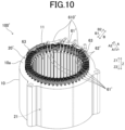
- FIG. 10 is a perspective view of a stator 100' according to the comparative example.
- the stator 100' according to the comparative example is different in that part of power line terminals 61' and neutral line terminals 62' are disposed radially inward of the stator core 10.
- the power line terminals 61 and neutral line terminals 62 of each phase are all disposed radially outward of the stator core 10.
- This configuration can avoid the disadvantage that occurs when at least one power line terminal 61 is disposed on the radially inner side. That is, unlike the comparative example described above with reference to FIG. 10 , an increase in axial size of the stator 100 due to the stator coil 20 can be prevented.
- the present embodiment can reduce the axial size of the stator 100 while setting the number of parallel-connected coil portions of each phase to four.
- the power line terminals 61 can be disposed axially inward of the axially outermost position of the crossover portions 22 (i.e., the axially outermost position of the coil end, see line L3) as viewed in the radial direction. This can prevent an increase in axial size of the stator 100 due to the power line terminals 61, and thus can reduce the axial size of the stator 100.
- wires connected to the power line terminals 61 namely wires connected to an inverter, not shown (e.g., wires in the form of a cable) can also be disposed axially inward of the axially outermost position of the crossover portions 22 as viewed in the radial direction.
- the neutral line terminals 62 and neutral point busbars 63 connecting the neutral line terminals 62 can be disposed axially inward of the axially outermost position of the crossover portions 22 (i.e., the axially outermost position of the coil end, see line L3) as viewed in the radial direction.
- This can prevent an increase in axial size of the stator 100 due to the neutral line terminals 62 and the neutral point busbars 63 connecting the neutral line terminals 62, and thus can reduce the axial size of the stator 100.
- the present embodiment has the following effects in addition to the above effects.
- the first crossover portions 23 form the wave winding portions 20a to 20d that are wave-wound around the stator core 10 together with the slot insertion portions 21 by connecting the slot insertion portions 21 in pairs so that the radial positions of the connected slot insertion portions 21 are gradually changed in order toward the one side in the radial direction. It is therefore possible to connect the slot insertion portions 21 without providing a portion where the radial position of the connected slot insertion portions 21 is switched at an intermediate position, unlike the case where radially adjacent slot insertion portions 21 are alternately connected in each of the plurality of slots 11.
- the second crossover portion 24 and the third crossover portion 25 connect the slot insertion portions 21 in pairs, so that one and the other of the wave winding portions forming one lap out of the wave winding portions 20a to 20d formed by the first crossover portions 23 and the slot insertion portions 21 are connected so as to be folded back.
- the second crossover portion 24 and the third crossover portion 25, each connecting the slot insertion portions 21 installed at the same radial position in the slots 11, can thus connect the wave winding portions 20a to 20d so as to fold back the wave winding portions 20a to 20d. This can prevent the shape of the folded-back portions from becoming complicated.
- one and the other of the wave winding portions forming one lap out of the wave winding portions 20a to 20d are installed so that the radial positions of the connected slot insertion portions 21 are changed gradually and parallel to each other. Therefore, the conductors (coil pieces 70) having the same shape can be used as conductors forming one of the wave winding portions forming one lap out of the wave winding portions 20a to 20d and conductors forming the other wave winding portion. This can reduce the number of types of coil pieces 70 for forming the stator coil 20, even when the wave winding portions forming one lap out of the wave winding portions 20a to 20d are connected so as to be folded back.
- the wave-wound stator coil 20 folded back a plurality of times is formed using the plurality of wave winding portions 20a to 20d, the second crossover portions 24 (outermost coil end portion), and the third crossover portions 25 (innermost coil end portion). Therefore, the stator coil 20 can be formed so as to be wave-wound by folding back a plurality of times on each of the radially innermost and outermost sides in the slots 11. Accordingly, even when a large number of slot insertion portions 21 is housed in one slot 11, the stator coil 20 can be formed by folding back a plurality of times on each of the radially innermost and outermost sides in the slots 11. This can reduce an increase in number of types of coil pieces 70 that form the stator coil 20.
- the stator coil 20 can be formed by connecting pairs of slot insertion portions 21 installed at positions shifted outward or inward in the radial direction from each other by one. Therefore, the slot insertion portions 21 can be densely installed in each of the plurality of slots 11. Accordingly, the slot insertion portions 21 can be connected in pairs so that the radial positions of the connected slot insertion portions 21 are gradually changed in order toward the one side in the radial direction, while allowing efficient connection of the plurality of slot insertion portions 21 installed in the slots 11.
- the slot insertion portions 21 are installed in the same slots 11 in both one and the other of the wave winding portions forming one lap out of the wave winding portions 20a to 20d, the positional relationship of the stator coil 20 with the magnets installed in the rotor 150 facing the stator 100 becomes uneven. Therefore, currents flowing through the wave winding portions 20a to 20d become uneven.
- the slot insertion portions 21 forming one of the wave winding portions forming one lap out of the wave winding portions 20a to 20d and the slot insertion portions 21 forming the other of the wave winding portions forming the lap out of the wave winding portions 20a to 20d are installed in adjacent slots 11. Therefore, currents flowing through the wave winding portions 20a to 20d are less likely to become uneven.
- all of the neutral line terminals 62 are also disposed on the radially outer side.
- part or all of the neutral line terminals 62 may be disposed radially inward of the stator core 10. That is, part or all of the second slot insertion portions 21B may be installed on the radially outermost side in the slots 11.
- the above embodiment illustrates an example in which the first crossover portions 23 that form one of the wave winding portions forming one lap out of the wave winding portions 20a to 20d and the first crossover portions 23 that form the other wave winding portion are provided so that the radial positions of the connected slot insertion portions 21 are changed gradually and parallel to each other.
- the present disclosure is not limited to this.
- the radial positions of the slot insertion portions 21 in one of the wave winding portions forming one lap may not be parallel to the radial positions of the slot insertion portions 21 in the other wave winding portion.
- the above embodiment illustrates an example in which the wave winding portions 20a to 20d are folded back on the radially outermost and innermost sides.
- the present disclosure is not limited to this.
- the wave winding portions 20a to 20d may be folded back at an intermediate position in the radial direction.
Landscapes
- Engineering & Computer Science (AREA)
- Power Engineering (AREA)
- Windings For Motors And Generators (AREA)
Abstract
Description
- The present disclosure relates to stators for rotating electrical machines.
- A technique is known in which, of both ends of a plurality of coil pieces forming a stator coil, one ends are installed on the radially outermost side of the stator core in slots, and the other ends are installed on the radially innermost side of the stator core in the slots.
- Patent Document 1:
Japanese Unexamined Patent Application Publication No. 2019-201485 JP 2019-201485 A - In such related art as described above, it is necessary to route wires from the ends of the coil pieces on the radially innermost side radially outward (across a coil end in a radial direction) at a position radially outward of the coil end, which tends to lead to an increase in axial size of the stator coil. Particularly when the number of parallel-connected coil portions of each phase is four or more, the number of terminals increases. Therefore, such an arrangement of the terminals on the radially inner side tends to be used.
- Therefore, in one aspect, an object of the present embodiment is to reduce the axial size of a stator while setting the number of parallel-connected coil portions of each phase to four or more.
- One aspect provides a stator for a rotating electrical machine. The stator includes: a stator coil in which four or more sets of coil portions for each of phases are connected as a parallel circuit between a neutral line terminal and a power line terminal for each of the phases; and a stator core that has a plurality of slots and around which the stator coil is wound.
- The stator coil includes
slot insertion portions each inserted in a corresponding one of the plurality of slots, and a crossover portion exposed from an axial end face of the stator core and extending in a circumferential direction so as to connect a pair of the slot insertion portions. - In each of the phases, a first slot insertion portion directly connected to the power line terminal out of a plurality of the slot insertion portions in each of the four or more sets is located on a radially outermost side in a corresponding one of the slots on one side in an axial direction of the stator core.
- In the one aspect, the present embodiment can reduce the axial size of a stator while setting the number of parallel-connected coil portions of each phase to four or more.
-
- [
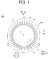
FIG. 1] FIG. 1 is a plan view of a rotating electrical machine (stator) according to an embodiment. - [
FIG. 2] FIG. 2 is a circuit diagram of a three-phase coil connected in a Y-configuration according to the embodiment. - [
FIG. 3] FIG. 3 is a perspective view of the stator according to the embodiment. - [
FIG. 3A] FIG. 3A is a side view of the stator according to the embodiment. - [
FIG. 3B] FIG. 3B is a top view of the stator according to the embodiment. - [
FIG. 3C] FIG. 3C is a diagram illustrating the configuration of coil pieces that form a stator coil. - [
FIG. 4] FIG. 4 is a diagram showing the configuration of a U1 coil of a U-phase coil. - [
FIG. 5] FIG. 5 is a diagram showing the configuration of a U2 coil of the U-phase coil. - [
FIG. 6] FIG. 6 is a diagram showing the configuration of a U3 coil of the U-phase coil. - [
FIG. 7] FIG. 7 is a diagram showing the configuration of a U4 coil of the U-phase coil. - [
FIG. 8] FIG. 8 is a diagram showing an arrangement of terminals for the U-phase coil. - [
FIG. 9A] FIG. 9A is a diagram illustrating second crossover portions each connecting slot insertion portions of the first turn on the radially outermost side. - [
FIG. 9B] FIG. 9B is a diagram illustrating third crossover portions each connecting slot insertion portions of the eighth turn on the radially innermost side. - [
FIG. 10] FIG. 10 is a perspective view of a stator according to a comparative example. - Embodiments will be described in detail below with reference to the accompanying drawings. The dimensional ratios in the drawings are merely illustrative, and are not limited to these. The shapes etc. in the drawings may be partially exaggerated for convenience of description. Regarding a plurality of the same components in
FIG. 1 (and inFIG. 3 and the subsequent figures as well), only part of the components may be denoted with a sign for simplicity. -
FIG. 1 is a plan view of a rotating electrical machine (stator) according to an embodiment. - In the present specification, the "axial direction" means a direction along an axis (sign O) of a stator core 10 (rotor 150) (Z direction: see
FIG. 1 ). One side in the axial direction will be referred to as Z1 direction side, and the other side in the axial direction will be referred to as Z2 direction side. The "circumferential direction" means a circumferential direction of the stator core 10 (A direction). One side in the circumferential direction will be referred to as A1 direction, and the other side in the circumferential direction will be referred to as A2 direction. The "radial direction" means a radial direction about the axis of the stator core 10 (rotor 150) (B direction). The terms "radially inward" and "radially inner side" mean a direction toward the center of the stator core 10 (B1 direction). The terms "radially outward" and "radially outer side" mean a direction toward the outside of the stator core 10 (B2 direction). - As shown in
FIG. 1 , a rotatingelectrical machine 200 includes astator 100 and therotor 150. Thestator 100 and therotor 150 are each formed in an annular shape. Thestator 100 and therotor 150 face each other. Therotor 150 is disposed radially inward of (on the B1 direction side of) thestator 100. Therotor 150 is provided with a plurality of permanent magnets (not shown). That is, the rotatingelectrical machine 200 of the present embodiment is configured as an inner rotor type rotating electrical machine. - The
stator 100 includes thestator core 10. Thestator core 10 is disposed so as to face therotor 150 in the radial direction. Thestator core 10 has a plurality of (e.g., 48)slots 11.Teeth 12 are each located between adjacent ones of theslots 11. Thestator core 10 is composed of, for example, a plurality of electrical steel laminations stacked in a direction of its central axis of rotation (Z1 direction and Z2 direction), and is configured to allow magnetic flux to pass therethrough. Thestator core 10 may be formed by compression molding of magnetic powder. Thestator core 10 includes end faces 10a on both its one side in the axial direction (Z1 direction side) and the other side in the axial direction (Z2 direction side). Thestator 100 includes astator coil 20. -
FIG. 2 is a circuit diagram of a three-phase coil connected in a Y-configuration according to the present embodiment. - As shown in
FIG. 2 , thestator coil 20 is connected to an external power supply unit, and is configured to be supplied with electric power (e.g. three-phase alternating current power). Thestator coil 20 is configured to generate a magnetic field when supplied with electric power. Thestator coil 20 includes aU-phase coil 30, a V-phase coil 40, and a W-phase coil 50 through which three-phase (U-phase, V-phase, and W-phase) alternating currents flow, respectively. - The
U-phase coil 30 includes aU1 coil portion 31, aU2 coil portion 32, aU3 coil portion 33, and aU4 coil portion 34 that are connected in parallel with each other. The V-phase coil 40 includes aV1 coil portion 41, aV2 coil portion 42, aV3 coil portion 43, and aV4 coil portion 44 that are connected in parallel with each other. The W-phase coil 50 includes aW1 coil portion 51, a W2 coil portion 52, aW3 coil portion 53, and a W4 coil portion 54 that are connected in parallel with each other. TheU-phase coil 30, the V-phase coil 40, and the W-phase coil 50 are connected in a Y-configuration (star configuration). That is, a so-called "4Y" configuration is implemented. Alternating current power for each of the U-phase, V-phase, and W-phase is input from apower line terminal 61 to theU-phase coil 30, the V-phase coil 40, and the W-phase coil 50, respectively. The output sides of theU-phase coil 30, V-phase coil 40, and W-phase coil 50 are connected to each other via aneutral line terminal 62. -
FIG. 3 is a perspective view of thestator 100 according to the present embodiment.FIG. 3A is a side view of thestator 100 according to the present embodiment.FIG. 3B is a top view of thestator 100 according to the present embodiment.FIG. 3C is a diagram illustrating the configuration ofcoil pieces 70 that form thestator coil 20. - As shown in
FIG. 3 , thestator coil 20 is wound around thestator core 10. In the present embodiment, thestator coil 20 has a wave winding configuration in which a plurality of coil pieces 70 (FIG. 3C ) is installed in each of the plurality ofslots 11. Specifically, as shown inFIG. 3C , thestator coil 20 is formed as a wave-wound coil of conductor wires by connecting the plurality ofcoil pieces 70. Each of the plurality ofcoil pieces 70 may have an inverted U-shape as viewed with the Z1 side facing upward. Each of the plurality ofcoil pieces 70 may be in the form of a flat conductor wire having a rectangular cross section and coated with an insulating coating. - Each of the plurality of
coil pieces 70 includesslot insertion portions 21 andcrossover portions 22. - The
slot insertion portions 21 extend in the axial direction (Z direction) and are placed in each of the plurality ofslots 11. - The
crossover portions 22 connect the plurality ofslot insertion portions 21 to each other in pairs. That is, thecrossover portions 22 each connect theslot insertion portions 21 installed indifferent slots 11. Thecrossover portions 22 are formed on both the Z2 direction side and the Z1 direction side. Regarding the shape of thecrossover portions 22, each of afirst crossover portion 23, asecond crossover portion 24, and athird crossover portion 25, which will be described later, has a different shape. - As shown in
FIG. 3C , after thecoil pieces 70 are installed such that theslot insertion portions 21 are housed in each of theslots 11, thecrossover portions 22 on the Z2 direction side may be bent outward in the circumferential direction and joined to thecrossover portions 22 on the Z2 direction side ofdifferent coil pieces 70 by laser joining etc. - In the
stator coil 20, theU-phase coil 30, the V-phase coil 40, and the W-phase coil 50 have substantially the same configuration. TheU-phase coil 30 will be mainly described below. - The
U-phase coil 30 is installed in thestator core 10 such that four sets, namely theU1 coil portion 31, theU2 coil portion 32, theU3 coil portion 33, and theU4 coil portion 34, form a parallel circuit. One end of each of theU1 coil portion 31,U2 coil portion 32,U3 coil portion 33, andU4 coil portion 34 is connected to thepower line terminal 61. Alternating current power is supplied from thepower line terminal 61. The other end of each of theU1 coil portion 31,U2 coil portion 32,U3 coil portion 33, andU4 coil portion 34 is connected to theneutral line terminal 62. -
FIG. 4 is a diagram showing the configuration of theU1 coil portion 31 of the U-phase coil.FIG. 5 is a diagram showing the configuration of theU2 coil portion 32 of the U-phase coil.FIG. 6 is a diagram showing the configuration of theU3 coil portion 33 of the U-phase coil.FIG. 7 is a diagram showing the configuration of theU4 coil portion 34 of the U-phase coil.FIG. 8 is a diagram showing arrangement of terminals for the U-phase coil 30 (power line terminals 61 and neutral line terminals 62), illustrating only a radially outermost portion of the U-phase coil 30 (portion corresponding to one radially outermost turn).FIG. 9A is a diagram illustratingsecond crossover portions 24 each connecting theslot insertion portions 21 of the first turn on the radially outermost side.FIG. 9B is a diagram illustratingthird crossover portions 25 each connecting theslot insertion portions 21 of the eighth turn on the radially innermost side. - As shown in
FIGS. 4 to 7 , theU1 coil portion 31,U2 coil portion 32,U3 coil portion 33, andU4 coil portion 34 of theU-phase coil 30 are installed in the followingslots 11 out of the 48 slots 11: #1 (hereinafter, "#" represents the number of the slot 11), #6, #7, #12, #13, #18, #19, #24, #25, #30, #31, #36, #37, #42, #43, and #48. Theslots 11 of #1 and #48, theslots 11 of #6 and #7, theslots 11 of #12 and #13, theslots 11 of #18 and #19, theslots 11 of #24 and #25, theslots 11 of #30 and #31, theslots 11 of #36 and #37, and theslots 11 of #42 and #43 are each twoslots 11 that are adjacent to each other in the circumferential direction (A direction). Note thatFIGS. 4 to 7 are diagrams of theannular stator core 10 shown opened out flat with the up-down direction being the radial direction of the stator core 10 (B direction) and the left-right direction being the circumferential direction of the stator core 10 (A direction). That is, the right and left ends shown inFIGS. 4 to 7 are continuous with each other. Although not shown in the figures, the V-phase coil 40 and the W-phase coil 50 are installed in thestator core 10 so as to be shifted from theU-phase coil 30 by twoslots 11 and fourslots 11, respectively. - A plurality of
slot insertion portions 21 is housed next to each other in the radial direction of the stator core 10 (B direction) in each of the plurality ofslots 11. Specifically, in the present embodiment, eightslot insertion portions 21 are arranged in a row in the radial direction in oneslot 11. For example, in oneslot 11, theslot insertion portion 21 installed on the outermost side (radially outer side: B2 direction side) is referred to as first turn (first layer), and theslot insertion portion 21 installed on the innermost side (radially inner side: B1 side) is referred to as eighth turn (eighth layer). InFIGS. 4 to 7 , theslot insertion portions 21 are installed at positions shown by white numbers on black backgrounds so that a current (current that flows from the power supply unit toward theU-phase coil 30 out of the alternating currents) flows in the order of the white numbers. - In the present embodiment, the
crossover portions 22 includefirst crossover portions 23,second crossover portions 24, andthird crossover portions 25. InFIGS. 4 to 7 , the crossover portions 22 (first crossover portions 23,second crossover portions 24, and third crossover portions 25) shown by continuous lines are located on the Z1 direction side of thestator core 10, and the crossover portions 22 (first crossover portions 23) shown by dashed lines are located on the Z2 direction side of thestator core 10. InFIGS. 4 to 7 , the crossover portions 22 (first crossover portions 23,second crossover portions 24, and third crossover portions 25) are schematically shown as straight lines as viewed in the Z direction. However, the crossover portions 22 (first crossover portions 23,second crossover portions 24, and third crossover portions 25) may have a curved shape as viewed in the Z direction. - The
first crossover portions 23 each connects a pair ofslot insertion portions 21 installed at different positions in the radial direction (B direction) out of the plurality ofslot insertion portions 21 housed indifferent slots 11. Specifically, thefirst crossover portions 23 connect theslot insertion portions 21 so that the radial positions (turn numbers) of the connectedslot insertion portions 21 are gradually changed in order toward one side in the radial direction. That is, thefirst crossover portions 23 connect theslot insertion portions 21 in pairs so that their turn numbers increase toward the one side in the circumferential direction (A1 direction side). Suchfirst crossover portions 23 andslot insertion portions 21 form four wave winding portions each wave-wound around thestator core 10, namely awave winding portion 20a, awave winding portion 20b, awave winding portion 20c, and awave winding portion 20d. - In the present embodiment, in each of the
wave winding portions 20a to 20d, a plurality offirst crossover portions 23 andslot insertion portions 21 are connected to each other, so that theslot insertion portion 21 installed on the radially outermost side (first turn) to theslot insertion portion 21 installed on the radially innermost side (eighth turn) are connected in order. That is, the plurality offirst crossover portions 23 connects theslot insertion portions 21 in pairs so that the radial positions of the connectedslot insertion portions 21 are gradually changed in order from theslot insertion portion 21 installed at the position of the first turn, namely at the end on the other side in the radial direction (e.g., the B2 direction side) of theslot 11, to theslot insertion portion 21 installed at the position of the eighth turn, namely at the end on the one side in the radial direction (e.g., the B1 direction side) of theslot 11. In the present embodiment, thefirst crossover portions 23 each connect a pair ofslot insertion portions 21 installed at positions shifted outward or inward in the radial direction (B direction) from each other by one out of theslot insertion portions 21 installed indifferent slots 11. That is, in each of thewave winding portions 20a to 20d, thefirst crossover portions 23 connect theslot insertion portions 21 so that the connectedslot insertion portions 21 are shifted by one turn in order from the eighth turn to the first turn. - The
wave winding portions 20a to 20d are provided so as to form at least one lap (two laps in the present embodiment). Onewave winding portion 20a is wave-wound along the one side in the circumferential direction of the stator core 10 (e.g., the A1 direction) toward the one side in the circumferential direction by theslot insertion portions 21 and thefirst crossover portions 23. Thewave winding portion 20b connected to thewave winding portion 20a is wave-wound along the other side in the circumferential direction (e.g., the A2 direction), namely the opposite side to the side along which thewave winding portion 20a is wave-wound, toward the other side in the circumferential direction. Similarly, thewave winding portion 20c and thewave winding portion 20d are also wave-wound toward the one side and the other side in the circumferential direction, respectively. Each of theU1 coil portion 31,U2 coil portion 32,U3 coil portion 33, andU4 coil portion 34 of theU-phase coil 30 in thestator coil 20 is formed by connecting thewave winding portion 20a, thewave winding portion 20b, thewave winding portion 20c, and thewave winding portion 20d in this order. That is, each of theU1 coil portion 31, theU2 coil portion 32, theU3 coil portion 33, and theU4 coil portion 34 is installed in thestator core 10 so as to be folded back three times in the circumferential direction. - In the present embodiment, the
wave winding portions 20a to 20d are connected to each other by either thesecond crossover portion 24 or thethird crossover portion 25. Each of thesecond crossover portion 24 and thethird crossover portion 25 connects a pair ofslot insertion portions 21 installed at the same radial position (turn number) out of the plurality ofslot insertion portions 21 housed indifferent slots 11. Specifically, thesecond crossover portion 24 connects theslot insertion portions 21 installed on the radially outermost side (first turn) in each of a plurality ofslots 11. Thethird crossover portion 25 connects theslot insertion portions 21 installed on the radially innermost side (eighth turn) in each of a plurality ofslots 11. Theslot insertion portions 21 are connected in pairs by thesecond crossover portion 24 or thethird crossover portion 25. Therefore, thewave winding portions 20a to 20d formed by thefirst crossover portions 23 and theslot insertion portions 21 are connected so that one and the other of the wave winding portions forming one lap are folded back. For example, in theU1 coil portion 31, fourwave winding portions 20a to 20d, onesecond crossover portion 24, and twothird crossover portions 25 form one wave-wound conductor folded back a plurality of times. - Specifically, as shown in
FIG. 4 , in theU1 coil portion 31, thepower line terminal 61 is connected to theslot insertion portion 21 installed on the radially outermost side (first turn) (portion shown by the white number 1) in theslot 11 of #37. Thepower line terminal 61 may be in the form of an end of acoil piece 70, or may be in the form of a separate member joined to an end of acoil piece 70. After theslot insertion portion 21 extends in the Z2 direction along theslot 11, afirst crossover portion 23 extends from #37 to #31 as acrossover portion 22 on the Z2 direction side. On the Z2 direction side of thestator core 10, thefirst crossover portion 23 is connected to theslot insertion portion 21 of the second turn (portion shown by the number 2) that is one turn inside from the radially outermost turn in theslot 11 of #31. Thereafter,first crossover portions 23 are connected to slotinsertion portions 21 alternately on the Z1 direction side and the Z2 direction side in the order of the third turn in theslot 11 of #25, the fourth turn in theslot 11 of #19, and the fifth turn in theslot 11 of #13, and are connected up to theslot insertion portion 21 of the eighth turn in theslot 11 of #43 (portion shown by the number 8) in such a manner that the turn number increases in increments of one toward the inner side for each connection. Thewave winding portion 20a is thus formed by connecting eightslot insertion portions 21 and sevenfirst crossover portions 23. - A
third crossover portion 25 is provided on the Z1 direction side of thestator core 10 from theslot insertion portion 21 of the eighth turn in theslot 11 of #43 (portion shown by the white number 8) to theslot insertion portion 21 of the eighth turn in theslot 11 of #48 (portion shown by the number 9) so as to make a fold. After being folded back by thethird crossover portion 25 to change the direction to the A2 direction side in the circumferential direction, thewave winding portion 20b is formed in the same manner as that of thewave winding portion 20a from theslot 11 of #48 in which the portion shown by thenumber 9 is provided to theslot 11 of #42. Asecond crossover portion 24 is provided on the Z1 direction side of thestator core 10 from theslot insertion portion 21 of the first turn in theslot 11 of #42 (portion shown by the number 16) to theslot insertion portion 21 of the first turn in theslot 11 of #1 (portion shown by the number 17). TheU1 coil portion 31 is thus folded back from thewave winding portion 20b to thewave winding portion 20c. Thereafter, theU1 coil portion 31 is similarly folded back from thewave winding portion 20c to thewave winding portion 20d by athird crossover portion 25. OneU1 coil portion 31 is thus formed by the fourwave winding portions 20a to 20d folded back three times. Theneutral line terminal 62 is connected to thewave winding portion 20d at theslot insertion portion 21 of the first turn in theslot 11 of #6 (portion shown by the number 32). Theneutral line terminal 62 may be in the form of an end of acoil piece 70, or may be in the form of a separate member joined to an end of acoil piece 70. - The
first crossover portions 23 thus connect the second turn to the third turn, the fourth turn to the fifth turn, and the sixth turn to the seventh turn, and are disposed on the Z1 direction side. Thesecond crossover portion 24 connecting the first turns and thethird crossover portions 25 connecting the eighth turns are all disposed on the Z1 direction side. Thepower line terminal 61 and theneutral line terminal 62 are also connected on the Z1 direction side. - In the following description, regarding the plurality of
slot insertion portions 21, when distinguishing theslot insertion portion 21 that is directly connected to the power line terminal 61 (in theU1 coil portion 31, theslot insertion portion 21 inserted in theslot 11 of #37) from the otherslot insertion portions 21, thisslot insertion portion 21 will also be referred to as "firstslot insertion portion 21A." Regarding the plurality ofslot insertion portions 21, when distinguishing theslot insertion portion 21 that is directly connected to the neutral line terminal 62 (slot insertion portion 21 inserted in theslot 11 of #6) from the otherslot insertion portions 21, thisslot insertion portion 21 will also be referred to as "secondslot insertion portion 21B." Regarding the plurality ofslot insertion portions 21, when distinguishing theslot insertion portions 21 inserted on the radially innermost side (eighth turn) in the slots 11 (slot insertion portions 21 inserted in theslots 11 of #7, #12, #43, and #48) from the otherslot insertion portions 21, theseslot insertion portions 21 will also be referred to as "thirdslot insertion portions 21C." - In the present embodiment, as described above, each
slot insertion portion 21 along the direction of the current flow from the firstslot insertion portion 21A to the secondslot insertion portion 21B is inserted in acorresponding slot 11 in such a manner that the trend of change (increase and decrease) of the slot number is reversed at least once (in this example, three times). The "slot number" as used herein increases relatively in order clockwise or counterclockwise in the circumferential direction of thestator core 10 as viewed in the axial direction. In the case of the present embodiment, when #1 to #48 correspond to slot numbers, the direction in which the number increases in increments of one from #1 to #48 corresponds to the direction in which the slot number increases, and the direction in which the number changes from #48 via #1 also corresponds to the direction in which the slot number increases. The direction in which the number decreases in increments of one from #48 to #1 corresponds to the direction in which the slot number decreases, and the direction in which the number changes from #1 via #48 also corresponds to the direction in which the slot number decreases. - Particularly in the present embodiment, in each of the
U1 coil portion 31,U2 coil portion 32,U3 coil portion 33, andU4 coil portion 34, the direction of increase and decrease of the slot number of eachslot insertion portion 21 along the direction of the current flow from the firstslot insertion portion 21A to the secondslot insertion portion 21B is reversed starting at the thirdslot insertion portion 21C. For example, in the case of theU1 coil portion 31, eachslot insertion portion 21 is inserted in a corresponding slot in such a manner that the slot number decreases from the firstslot insertion portion 21A to the first thirdslot insertion portion 21C in the direction of the current flow (thirdslot insertion portion 21C inserted in theslot 11 of #43) and that the slot number increases from the last thirdslot insertion portion 21C in the direction of the current flow (thirdslot insertion portion 21C inserted in theslot 11 of #12) to the secondslot insertion portion 21B. - In the present embodiment, in each of the
U1 coil portion 31,U2 coil portion 32,U3 coil portion 33, andU4 coil portion 34, the radial position of eachslot insertion portion 21 along the direction of the current flow from the firstslot insertion portion 21A to the secondslot insertion portion 21B is changed regularly. For example, in the case of theU1 coil portion 31, when the slot number decreases, the radial position in theslot 11 is shifted radially inward by one turn (see the first crossover portions 23). When the slot number increases, the radial position in theslot 11 is shifted radially outward by one turn (see the first crossover portions 23) or the same radial position is maintained (see thesecond crossover portion 24 and the third crossover portions 25). - As shown in
FIGS. 5 to 7 , like theU1 coil portion 31, each of theU2 coil portion 32,U3 coil portion 33, andU4 coil portion 34 is also configured as part of the wave-wound stator coil 20 folded back a plurality of times by folding back the fourwave winding portions 20a to 20d. - Particularly in the present embodiment, in each of the
U2 coil portion 32,U3 coil portion 33, andU4 coil portion 34, thepower line terminal 61 and theneutral line terminal 62 are both disposed on the radially outer side, as in theU1 coil portion 31. That is, as shown inFIG. 8 , thepower line terminals 61 andneutral line terminals 62 of each phase are all disposed radially outward of thestator core 10. InFIG. 8 , the symbols U, V, and W represent the phases, and thenumerals 1 to 4 following the symbols U, V, and W represent the corresponding one of the four sets. For example, U1 to U4 represent theU1 coil portion 31, theU2 coil portion 32, theU3 coil portion 33, and theU4 coil portion 34, respectively. Moreover, "_in" and "_out" at the end represent thepower line terminal 61 and theneutral line terminal 62, respectively. - In the present embodiment, regarding the
U-phase coil 30, thepower line terminals 61 for theU1 coil portion 31 andU2 coil portion 32 and thepower line terminals 61 for theU3 coil portion 33 andU4 coil portion 34 are set at diagonal positions in the circumferential direction, as shown inFIG. 3B . The same applies to the V-phase coil 40 and the W-phase coil 50. - In the present embodiment, the
first crossover portions 23 that form one of the wave winding portions forming one lap out of thewave winding portions 20a to 20d and thefirst crossover portions 23 that form the other of the wave winding portions forming the lap connect theslot insertion portions 21 in pairs so that the radial positions of the connectedslot insertion portions 21 are changed gradually (like a slope) and parallel to each other. The number (pitch) ofslots 11 across which eachfirst crossover portion 23 extends is the same in each of the plurality ofwave winding portions 20a to 20d. Specifically, each of thefirst crossover portions 23 extends across fiveslots 11 to connect theslot insertion portions 21 while shifting the turn by one. In other words, in each of the plurality ofwave winding portions 20a to 20d, the pitch of all thefirst crossover portions 23 is "6." Thefirst crossover portions 23 have the same pitch both on the one side (Z1 direction side) and the other side (Z2 direction side) of thestator core 10. As used herein, the term "parallel" means that the radial positions of theslot insertion portions 21 connected to thefirst crossover portions 23 are parallel in a state in which theslot insertion portions 21 are installed along the circumferential direction. That is, this means that the positions of theslot insertion portions 21 are parallel when theannular stator core 10 is shown opened out flat as inFIGS. 4 to 7 . - The
second crossover portions 24 and thethird crossover portions 25 each have two different pitches, namely a pitch of 5 and a pitch of 7. For example, in theU1 coil portion 31 ofFIG. 4 , asecond crossover portion 24 having a pitch of 7 is provided between theslots 11 of #42 and #1, andthird crossover portions 25 having a pitch of 5 are provided between theslots 11 of #43 and #48 and between theslots 11 of #7 and #12. In theU2 coil portion 32 ofFIG. 5 , on the other hand, asecond crossover portion 24 having a pitch of 5 is provided between theslots 11 of #43 and #48, andthird crossover portions 25 having a pitch of 7 are provided between theslots 11 of #42 and #1 and between theslots 11 of #6 and #13. - As shown in
FIGS. 9A and 9B , thesecond crossover portions 24 or thethird crossover portions 25 that are connected to theslot insertion portions 21 installed in thesame slots 11 and that have different pitches are disposed so as to overlap each other as viewed in the axial direction (Z direction). Thesecond crossover portion 24 or thethird crossover portion 25 that has a larger pitch is disposed above (on the Z1 direction side of) thesecond crossover portion 24 or thethird crossover portion 25 that has a smaller pitch. Specifically, thesecond crossover portion 24 and thethird crossover portion 25 that have a pitch of 7 are disposed so as to cover, from above, thesecond crossover portion 24 and thethird crossover portion 25 that have a pitch of 5, respectively. - As shown in
FIGS. 4 to 7 , theslot insertion portions 21 that form one of the wave winding portions forming one lap out of thewave winding portions 20a to 20d and theslot insertion portions 21 that form the other of the wave winding portions forming the lap are installed inadjacent slots 11. TheU-phase coil 30, the V-phase coil 40, and the W-phase coil 50 are alternately installed in pairs ofadjacent slots 11 along the radial direction. - For example, in the
U1 coil portion 31 of the U-phase inFIG. 4 , theslot insertion portions 21 forming thewave winding portions 20a to 20d are housed in pairs ofslots 11 that are adjacent to each other in the circumferential direction, namely #1 and #48, #6 and #7, #12 and #13, #18 and #19, #24 and #25, #30 and #31, #36 and #37, and #42 and #43. In adjacent ones of thewave winding portions 20a to 20d (wave winding portions forming one lap), theslot insertion portions 21 are alternately installed indifferent slots 11. The U-phaseU2 coil portion 32,U3 coil portion 33, andU4 coil portion 34 inFIGS. 5 to 7 are installed in the same manner as that of the U-phaseU1 coil portion 31. The positional relationship with the permanent magnets, not shown, of therotor 150 is therefore less likely to become uneven among theU1 coil portion 31,U2 coil portion 32,U3 coil portion 33, andU4 coil portion 34 of the U-phase. - In the present embodiment, the
stator coil 20 is formed using seven types ofcoil pieces 70. That is, the followingcoil pieces 70 are used: three types ofcoil pieces 70 that form a pair ofslot insertion portions 21 and afirst crossover portion 23, two types ofcoil pieces 70 that form a pair ofslot insertion portions 21 and asecond crossover portion 24, and two types ofcoil pieces 70 that form a pair ofslot insertion portions 21 and athird crossover portion 25. The three types ofcoil pieces 70 that form a pair ofslot insertion portions 21 and afirst crossover portion 23 are the following three types of coil pieces 70: acoil piece 70 whosefirst crossover portion 23 connects the second turn and the third turn on the Z1 direction side, acoil piece 70 whosefirst crossover portion 23 connects the fourth turn and the fifth turn on the Z1 direction side, and acoil piece 70 whosefirst crossover portion 23 connects the sixth turn and the seventh turn on the Z1 direction side. The two types ofcoil pieces 70 that form a pair ofslot insertion portions 21 and asecond crossover portion 24 and the two types ofcoil pieces 70 that form a pair ofslot insertion portions 21 and athird crossover portion 25 each have two different pitches, namely 5 and 7. - Effects of the present embodiment will be described with reference to a comparative example shown in
FIG. 10 for comparison. -
FIG. 10 is a perspective view of a stator 100' according to the comparative example. The stator 100' according to the comparative example is different in that part of power line terminals 61' and neutral line terminals 62' are disposed radially inward of thestator core 10. - In such a comparative example, as described above in the section "Problem to be Solved by the Invention," it is necessary to route wires from the radially innermost power line terminals 61' (see, for example, cables 610' in
FIG. 10 ) radially outward (across a coil end in the radial direction) at a position radially outward of the coil end, which tends to lead to an increase in axial size of the stator 100' due to the stator coil 20'. Particularly when the number of parallel-connected coil portions of each phase is four or more as in the present embodiment, the number of terminals increases. Therefore, such an arrangement of the terminals on the radially inner side tends to be used. - According to the present embodiment, on the other hand, as described above, the
power line terminals 61 andneutral line terminals 62 of each phase are all disposed radially outward of thestator core 10. This configuration can avoid the disadvantage that occurs when at least onepower line terminal 61 is disposed on the radially inner side. That is, unlike the comparative example described above with reference toFIG. 10 , an increase in axial size of thestator 100 due to thestator coil 20 can be prevented. In other words, the present embodiment can reduce the axial size of thestator 100 while setting the number of parallel-connected coil portions of each phase to four. - Therefore, according to the present embodiment, as shown in
FIG. 3A , thepower line terminals 61 can be disposed axially inward of the axially outermost position of the crossover portions 22 (i.e., the axially outermost position of the coil end, see line L3) as viewed in the radial direction. This can prevent an increase in axial size of thestator 100 due to thepower line terminals 61, and thus can reduce the axial size of thestator 100. In this case, wires connected to thepower line terminals 61, namely wires connected to an inverter, not shown (e.g., wires in the form of a cable) can also be disposed axially inward of the axially outermost position of thecrossover portions 22 as viewed in the radial direction. - According to the present embodiment, as shown in
FIG. 3A (andFIG. 3 ), theneutral line terminals 62 andneutral point busbars 63 connecting theneutral line terminals 62 can be disposed axially inward of the axially outermost position of the crossover portions 22 (i.e., the axially outermost position of the coil end, see line L3) as viewed in the radial direction. This can prevent an increase in axial size of thestator 100 due to theneutral line terminals 62 and theneutral point busbars 63 connecting theneutral line terminals 62, and thus can reduce the axial size of thestator 100. - The present embodiment has the following effects in addition to the above effects.
- In the present embodiment, as described above, the
first crossover portions 23 form thewave winding portions 20a to 20d that are wave-wound around thestator core 10 together with theslot insertion portions 21 by connecting theslot insertion portions 21 in pairs so that the radial positions of the connectedslot insertion portions 21 are gradually changed in order toward the one side in the radial direction. It is therefore possible to connect theslot insertion portions 21 without providing a portion where the radial position of the connectedslot insertion portions 21 is switched at an intermediate position, unlike the case where radially adjacentslot insertion portions 21 are alternately connected in each of the plurality ofslots 11. This can reduce an increase in number of shapes of thecoil pieces 70 on the one side in the axial direction of thestator core 10, and can thus reduce an increase in number of types ofcoil pieces 70 for forming thestator coil 20. In the present embodiment, as described above, thesecond crossover portion 24 and thethird crossover portion 25 connect theslot insertion portions 21 in pairs, so that one and the other of the wave winding portions forming one lap out of thewave winding portions 20a to 20d formed by thefirst crossover portions 23 and theslot insertion portions 21 are connected so as to be folded back. Thesecond crossover portion 24 and thethird crossover portion 25, each connecting theslot insertion portions 21 installed at the same radial position in theslots 11, can thus connect thewave winding portions 20a to 20d so as to fold back thewave winding portions 20a to 20d. This can prevent the shape of the folded-back portions from becoming complicated. - In the present embodiment, as described above, one and the other of the wave winding portions forming one lap out of the
wave winding portions 20a to 20d are installed so that the radial positions of the connectedslot insertion portions 21 are changed gradually and parallel to each other. Therefore, the conductors (coil pieces 70) having the same shape can be used as conductors forming one of the wave winding portions forming one lap out of thewave winding portions 20a to 20d and conductors forming the other wave winding portion. This can reduce the number of types ofcoil pieces 70 for forming thestator coil 20, even when the wave winding portions forming one lap out of thewave winding portions 20a to 20d are connected so as to be folded back. - In the present embodiment, as described above, the
wave winding portions 20a to 20d can be formed so that theslot insertion portions 21 that are connected progressively from the end on the one side in the radial direction toward the end on the other side in the radial direction are installed in each of a plurality ofslots 11. Therefore, the ends of thewave winding portions 20a to 20d can be disposed on the radially outermost side. Therefore, in the case where thepower line terminals 61 or theneutral line terminals 62 etc. are connected to thestator coil 20, the manufacturing process is less likely to become complicated compared to the case where thepower line terminals 61 or theneutral line terminals 62 etc. are connected to intermediate portions of the conductors (coil pieces 70) in theslots 11. - In the present embodiment, as described above, the wave-
wound stator coil 20 folded back a plurality of times is formed using the plurality ofwave winding portions 20a to 20d, the second crossover portions 24 (outermost coil end portion), and the third crossover portions 25 (innermost coil end portion). Therefore, thestator coil 20 can be formed so as to be wave-wound by folding back a plurality of times on each of the radially innermost and outermost sides in theslots 11. Accordingly, even when a large number ofslot insertion portions 21 is housed in oneslot 11, thestator coil 20 can be formed by folding back a plurality of times on each of the radially innermost and outermost sides in theslots 11. This can reduce an increase in number of types ofcoil pieces 70 that form thestator coil 20. - In the present embodiment, as described above, the
stator coil 20 can be formed by connecting pairs ofslot insertion portions 21 installed at positions shifted outward or inward in the radial direction from each other by one. Therefore, theslot insertion portions 21 can be densely installed in each of the plurality ofslots 11. Accordingly, theslot insertion portions 21 can be connected in pairs so that the radial positions of the connectedslot insertion portions 21 are gradually changed in order toward the one side in the radial direction, while allowing efficient connection of the plurality ofslot insertion portions 21 installed in theslots 11. - In the case where the
slot insertion portions 21 are installed in thesame slots 11 in both one and the other of the wave winding portions forming one lap out of thewave winding portions 20a to 20d, the positional relationship of thestator coil 20 with the magnets installed in therotor 150 facing thestator 100 becomes uneven. Therefore, currents flowing through thewave winding portions 20a to 20d become uneven. In view of this, in the present embodiment, as described above, theslot insertion portions 21 forming one of the wave winding portions forming one lap out of thewave winding portions 20a to 20d and theslot insertion portions 21 forming the other of the wave winding portions forming the lap out of thewave winding portions 20a to 20d are installed inadjacent slots 11. Therefore, currents flowing through thewave winding portions 20a to 20d are less likely to become uneven. - Although the embodiments are described in detail above, the present disclosure is not limited to the specific embodiments, and various modifications and changes can be made within the scope of the claims. It is also possible to combine all or part of the constituent elements of the embodiments described above.
- For example, in the above embodiment, all of the
neutral line terminals 62 are also disposed on the radially outer side. However, part or all of theneutral line terminals 62 may be disposed radially inward of thestator core 10. That is, part or all of the secondslot insertion portions 21B may be installed on the radially outermost side in theslots 11. - The above embodiment illustrates an example in which the
first crossover portions 23 that form one of the wave winding portions forming one lap out of thewave winding portions 20a to 20d and thefirst crossover portions 23 that form the other wave winding portion are provided so that the radial positions of the connectedslot insertion portions 21 are changed gradually and parallel to each other. However, the present disclosure is not limited to this. For example, the radial positions of theslot insertion portions 21 in one of the wave winding portions forming one lap may not be parallel to the radial positions of theslot insertion portions 21 in the other wave winding portion. - The above embodiment illustrates an example in which the
wave winding portions 20a to 20d are folded back on the radially outermost and innermost sides. However, the present disclosure is not limited to this. For example, thewave winding portions 20a to 20d may be folded back at an intermediate position in the radial direction. - The above embodiment illustrates an example in which the
stator coil 20 folded back three times is formed using the fourwave winding portions 20a to 20d. However, the present disclosure is not limited to this. For example, thestator coil 20 may be configured to be folded back once using two wave winding portions. - The above embodiment illustrates an example in which the
first crossover portions 23 each connect a pair ofslot insertion portions 21 installed at positions shifted outward or inward in the radial direction from each other by one out of theslot insertion portions 21 installed indifferent slots 11. However, the present disclosure is not limited to this. For example, thefirst crossover portions 23 may each connect the slot insertion portions installed at positions shifted from each other by two or more slot insertion portions. That is, the slot insertion portions installed at positions shifted from each other by two or more turns may be connected to each other. - The above embodiment illustrates an example in which the
slot insertion portions 21 that form one of the wave winding portions forming one lap out of thewave winding portions 20a to 20d and theslot insertion portions 21 that form the other wave winding portion are installed inadjacent slots 11. However, the present disclosure is not limited to this. For example, the slot insertion portions that form one of the wave winding portions forming one lap and the slot insertion portions that form the other of the wave winding portions forming the lap may be installed in the same slots. Alternatively, the slot insertion portions that form one of the wave winding portions forming one lap and the slot insertion portions that form the other of the wave winding portions forming the lap may be installed in the slots separated from each other. - The above embodiment illustrates an example in which the
stator coil 20 is formed by the invertedU-shaped coil pieces 70. However, the present disclosure is not limited to this. For example, bar-shaped coil pieces may be installed as slot insertion portions in the slots, and the bar-shaped coil pieces may then be joined to separate coil pieces to form coil end portions. Alternatively, a coil portion may be formed by combining inverted U-shaped coil pieces and U-shaped coil pieces from one side and the other side in the axial direction of thestator core 10. - The above embodiment illustrates an example in which each of the
U-phase coil 30, V-phase coil 40, and W-phase coil 50 forms a coil with a four-parallel configuration. However, the present disclosure is not limited to this. For example, each of the U-phase coil, V-phase coil, and W-phase coil may have a six- or more parallel-connection configuration such as a six- or eight-parallel connection configuration. - The above embodiment illustrates an example in which the
stator core 10 is provided with 48slots 11 and eightslot insertion portions 21 are housed next to each other in the radial direction in eachslot 11. However, the present disclosure is not limited to this. For example, the number of slots in the stator core may be other than 48. The number of slot insertion portions housed in one slot may be other than eight. - 100 ... stator (stator for rotating electrical machine), 20 ... stator coil, 31 ... U1 coil portion (coil portion), 32 ... U2 coil portion (coil portion), 33 ... U3 coil portion (coil portion), 34 ... U4 coil portion (coil portion), 41 ... V1 coil portion (coil portion), 42 ... V2 coil portion (coil portion), 43 ... V3 coil portion (coil portion), 44 ... V4 coil portion (coil portion), 51 ... W1 coil portion (coil portion), 52 ... W2 coil portion (coil portion), 53 ... W3 coil portion (coil portion), 54 ... W4 coil portion (coil portion), 10 ... stator core, 11 ... slot, 21 ... slot insertion portion, 21A ... first slot insertion portion, 21B ... second slot insertion portion, 21C... third slot insertion portion, 22... crossover portion, 61 ... power line terminal, 62 ... neutral line terminal
Claims (7)
- A stator for a rotating electrical machine, the stator comprising:a stator coil in which four or more sets of coil portions for each of phases are connected as a parallel circuit between a neutral line terminal and a power line terminal for each of the phases; anda stator core that has a plurality of slots and around which the stator coil is wound, wherein:the stator coil includesslot insertion portions each inserted in a corresponding one of the plurality of slots, anda crossover portion exposed from an axial end face of the stator core and extending in a circumferential direction so as to connect a pair of the slot insertion portions; andin each of the phases, a first slot insertion portion directly connected to the power line terminal out of a plurality of the slot insertion portions in each of the four or more sets is located on a radially outermost side in a corresponding one of the slots on one side in an axial direction of the stator core.
- The stator for a rotating electrical machine according to claim 1, wherein in each of the phases, a second slot insertion portion directly connected to the neutral line terminal out of the plurality of slot insertion portions in each of the sets is located on the radially outermost side in a corresponding one of the slots on the one side in the axial direction of the stator core.
- The stator for a rotating electrical machine according to claim 2, wherein in each of the sets for one of the phases in the stator coil, each of the slot insertion portions along a direction of a current flow from the first slot insertion portion to the second slot insertion portion is inserted in a corresponding one of the slots in such a manner that a direction in which a slot number changes is reversed from a first direction to a second direction at least once, the slot number being a number that is given to each of the plurality of slots and that increases relatively in order clockwise or counterclockwise in the circumferential direction of the stator core as viewed in the axial direction, the first direction being one of the following two directions, and the second direction being another of the following two directions: a direction in which the slot number increases, and a direction in which the slot number decreases.
- The stator for a rotating electrical machine according to claim 3, wherein:in each of the phases, the plurality of slot insertion portions in each of the sets includes, in addition to the first slot insertion portion and the second slot insertion portion, at least one third slot insertion portion located on a radially innermost side in a corresponding one of the slots; andin each of the sets, each of the slot insertion portions along the direction of the current flow from the first slot insertion portion to the second slot insertion portion is inserted into a corresponding one of the slots in such a manner that the slot number changes in the first direction from the first slot insertion portion to a first third slot insertion portion in the direction of the current flow and that the slot number changes in the second direction from a last third slot insertion portion in the direction of the current flow to the second slot insertion portion.
- The stator for a rotating electrical machine according to claim 3, wherein in each of the sets, each of the slot insertion portions along the direction of the current flow from the first slot insertion portion to the second slot insertion portion is inserted into a corresponding one of the slots in such a manner that when the slot number changes in the first direction, a radial position in the slot is shifted radially inward by one turn, and that when the slot number changes in the second direction, the radial position in the slot is shifted radially outward by one turn or the same radial position is maintained.
- The stator for a rotating electrical machine according to claim 1, further comprising a neutral point busbar that connects a plurality of the neutral line terminals in the stator coil, wherein the neutral point busbar is located axially inward of an axially outermost position of the crossover portion as viewed in a radial direction.
- The stator for a rotating electrical machine according to any one of claims 1 to 6, wherein the power line terminal is located axially inward of an axially outermost position of the crossover portion as viewed in a radial direction.
Applications Claiming Priority (2)
| Application Number | Priority Date | Filing Date | Title |
|---|---|---|---|
| JP2022167302A JP7806652B2 (en) | 2022-10-19 | 2022-10-19 | Stator for rotating electrical machine |
| PCT/JP2023/035862 WO2024084934A1 (en) | 2022-10-19 | 2023-10-02 | Rotating electric machine stator |
Publications (2)
| Publication Number | Publication Date |
|---|---|
| EP4576507A1 true EP4576507A1 (en) | 2025-06-25 |
| EP4576507A4 EP4576507A4 (en) | 2025-12-10 |
Family
ID=90737714
Family Applications (1)
| Application Number | Title | Priority Date | Filing Date |
|---|---|---|---|
| EP23879581.9A Pending EP4576507A4 (en) | 2022-10-19 | 2023-10-02 | STATOR FOR AN ELECTRIC LATHE |
Country Status (5)
| Country | Link |
|---|---|
| US (1) | US20260135426A1 (en) |
| EP (1) | EP4576507A4 (en) |
| JP (1) | JP7806652B2 (en) |
| CN (1) | CN119923784A (en) |
| WO (1) | WO2024084934A1 (en) |
Families Citing this family (1)
| Publication number | Priority date | Publication date | Assignee | Title |
|---|---|---|---|---|
| WO2025248682A1 (en) * | 2024-05-29 | 2025-12-04 | Astemo株式会社 | Stator of rotary electrical machine, and rotary electrical machine |
Family Cites Families (6)
| Publication number | Priority date | Publication date | Assignee | Title |
|---|---|---|---|---|
| JP6410104B2 (en) | 2015-07-31 | 2018-10-24 | 株式会社デンソー | Rotating electric machine stator and rotating electric machine equipped with the stator |
| CN109586463B (en) | 2017-09-29 | 2021-08-10 | 比亚迪股份有限公司 | Stator assembly and motor and vehicle with same |
| CN109586458B (en) * | 2017-09-29 | 2021-04-20 | 比亚迪股份有限公司 | Stator assembly and electric machine and vehicle having the same |
| JP7070075B2 (en) | 2018-05-16 | 2022-05-18 | 株式会社アイシン | Rotating electric machine |
| CN111478465B (en) * | 2020-05-26 | 2025-06-03 | 上海威迈斯新能源有限公司 | Flat wire stator assembly and motor |
| JP2022136858A (en) | 2021-03-08 | 2022-09-21 | 日本電産株式会社 | motor |
-
2022
- 2022-10-19 JP JP2022167302A patent/JP7806652B2/en active Active
-
2023
- 2023-10-02 US US19/118,057 patent/US20260135426A1/en active Pending
- 2023-10-02 EP EP23879581.9A patent/EP4576507A4/en active Pending
- 2023-10-02 WO PCT/JP2023/035862 patent/WO2024084934A1/en not_active Ceased
- 2023-10-02 CN CN202380066908.XA patent/CN119923784A/en active Pending
Also Published As
| Publication number | Publication date |
|---|---|
| EP4576507A4 (en) | 2025-12-10 |
| CN119923784A (en) | 2025-05-02 |
| JP7806652B2 (en) | 2026-01-27 |
| WO2024084934A1 (en) | 2024-04-25 |
| JP2024060143A (en) | 2024-05-02 |
| US20260135426A1 (en) | 2026-05-14 |
Similar Documents
| Publication | Publication Date | Title |
|---|---|---|
| CN109075647B (en) | Rotary motor | |
| JP2004229459A (en) | Centralized winding stator coil for rotating electric machine | |
| JP7817940B2 (en) | Stator and Motor | |
| JP7655756B2 (en) | Motor | |
| JP7549007B2 (en) | Stator having a wave-wound coil structure, three-phase AC motor including the same, and method of manufacturing the stator | |
| EP2690757A2 (en) | Electricity collection and distribution ring and electric motor | |
| CN213990307U (en) | Motor stator and motor | |
| US20220286006A1 (en) | Motor | |
| CN111478477A (en) | Motor stator and motor | |
| CN111478478A (en) | Motor stator and motor | |
| EP1035630A2 (en) | Rotating electric machine and method for connecting coils of rotating electric machine | |
| CN115133690A (en) | Stator and motor | |
| CN115459497A (en) | motor | |
| CN104364997A (en) | Rotating electrical machines, stators for rotating electrical machines, and vehicles | |
| US20260135426A1 (en) | Stator for rotating electrical machine | |
| CN115242001A (en) | Hairpin conductor motor stator | |
| CN112583168A (en) | Motor stator winding, stator and motor | |
| CN104364996B (en) | Rotating electrical machines, stators for rotating electrical machines, and vehicles | |
| US20260058505A1 (en) | Stator, electrical rotating machine, stator winding method, and stator manufacturing method | |
| CN111478486A (en) | Motor stator and motor | |
| CN111478479A (en) | Motor stator and motor | |
| EP4518103A1 (en) | Stator and motor | |
| CN211908498U (en) | Motor stator and motor | |
| CN211880197U (en) | Motor stator and motor | |
| CN212033858U (en) | Motor stator and motor |
Legal Events
| Date | Code | Title | Description |
|---|---|---|---|
| STAA | Information on the status of an ep patent application or granted ep patent |
Free format text: STATUS: THE INTERNATIONAL PUBLICATION HAS BEEN MADE |
|
| PUAI | Public reference made under article 153(3) epc to a published international application that has entered the european phase |
Free format text: ORIGINAL CODE: 0009012 |
|
| STAA | Information on the status of an ep patent application or granted ep patent |
Free format text: STATUS: REQUEST FOR EXAMINATION WAS MADE |
|
| 17P | Request for examination filed |
Effective date: 20250317 |
|
| AK | Designated contracting states |
Kind code of ref document: A1 Designated state(s): AL AT BE BG CH CY CZ DE DK EE ES FI FR GB GR HR HU IE IS IT LI LT LU LV MC ME MK MT NL NO PL PT RO RS SE SI SK SM TR |
|
| A4 | Supplementary search report drawn up and despatched |
Effective date: 20251110 |
|
| RIC1 | Information provided on ipc code assigned before grant |
Ipc: H02K 3/28 20060101AFI20251104BHEP Ipc: H02K 3/50 20060101ALI20251104BHEP Ipc: H02K 3/12 20060101ALN20251104BHEP |
|
| DAV | Request for validation of the european patent (deleted) | ||
| DAX | Request for extension of the european patent (deleted) |