EP4576444A1 - Connector and electronic device - Google Patents
Connector and electronic device Download PDFInfo
- Publication number
- EP4576444A1 EP4576444A1 EP23870734.3A EP23870734A EP4576444A1 EP 4576444 A1 EP4576444 A1 EP 4576444A1 EP 23870734 A EP23870734 A EP 23870734A EP 4576444 A1 EP4576444 A1 EP 4576444A1
- Authority
- EP
- European Patent Office
- Prior art keywords
- electrical connection
- socket
- groove
- base
- board
- Prior art date
- Legal status (The legal status is an assumption and is not a legal conclusion. Google has not performed a legal analysis and makes no representation as to the accuracy of the status listed.)
- Pending
Links
Images





Classifications
-
- H—ELECTRICITY
- H01—ELECTRIC ELEMENTS
- H01R—ELECTRICALLY-CONDUCTIVE CONNECTIONS; STRUCTURAL ASSOCIATIONS OF A PLURALITY OF MUTUALLY-INSULATED ELECTRICAL CONNECTING ELEMENTS; COUPLING DEVICES; CURRENT COLLECTORS
- H01R13/00—Details of coupling devices of the kinds covered by groups H01R12/70 or H01R24/00 - H01R33/00
- H01R13/46—Bases; Cases
-
- H—ELECTRICITY
- H04—ELECTRIC COMMUNICATION TECHNIQUE
- H04M—TELEPHONIC COMMUNICATION
- H04M1/00—Substation equipment, e.g. for use by subscribers
- H04M1/02—Constructional features of telephone sets
- H04M1/0202—Portable telephone sets, e.g. cordless phones, mobile phones or bar type handsets
- H04M1/026—Details of the structure or mounting of specific components
- H04M1/0274—Details of the structure or mounting of specific components for an electrical connector module
-
- H—ELECTRICITY
- H01—ELECTRIC ELEMENTS
- H01R—ELECTRICALLY-CONDUCTIVE CONNECTIONS; STRUCTURAL ASSOCIATIONS OF A PLURALITY OF MUTUALLY-INSULATED ELECTRICAL CONNECTING ELEMENTS; COUPLING DEVICES; CURRENT COLLECTORS
- H01R13/00—Details of coupling devices of the kinds covered by groups H01R12/70 or H01R24/00 - H01R33/00
- H01R13/73—Means for mounting coupling parts to apparatus or structures, e.g. to a wall
- H01R13/74—Means for mounting coupling parts in openings of a panel
- H01R13/748—Means for mounting coupling parts in openings of a panel using one or more screws
-
- H—ELECTRICITY
- H01—ELECTRIC ELEMENTS
- H01R—ELECTRICALLY-CONDUCTIVE CONNECTIONS; STRUCTURAL ASSOCIATIONS OF A PLURALITY OF MUTUALLY-INSULATED ELECTRICAL CONNECTING ELEMENTS; COUPLING DEVICES; CURRENT COLLECTORS
- H01R12/00—Structural associations of a plurality of mutually-insulated electrical connecting elements, specially adapted for printed circuits, e.g. printed circuit boards [PCB], flat or ribbon cables, or like generally planar structures, e.g. terminal strips, terminal blocks; Coupling devices specially adapted for printed circuits, flat or ribbon cables, or like generally planar structures; Terminals specially adapted for contact with, or insertion into, printed circuits, flat or ribbon cables, or like generally planar structures
- H01R12/70—Coupling devices
- H01R12/71—Coupling devices for rigid printing circuits or like structures
- H01R12/72—Coupling devices for rigid printing circuits or like structures coupling with the edge of the rigid printed circuits or like structures
- H01R12/722—Coupling devices for rigid printing circuits or like structures coupling with the edge of the rigid printed circuits or like structures coupling devices mounted on the edge of the printed circuits
-
- H—ELECTRICITY
- H01—ELECTRIC ELEMENTS
- H01R—ELECTRICALLY-CONDUCTIVE CONNECTIONS; STRUCTURAL ASSOCIATIONS OF A PLURALITY OF MUTUALLY-INSULATED ELECTRICAL CONNECTING ELEMENTS; COUPLING DEVICES; CURRENT COLLECTORS
- H01R13/00—Details of coupling devices of the kinds covered by groups H01R12/70 or H01R24/00 - H01R33/00
- H01R13/02—Contact members
-
- H—ELECTRICITY
- H01—ELECTRIC ELEMENTS
- H01R—ELECTRICALLY-CONDUCTIVE CONNECTIONS; STRUCTURAL ASSOCIATIONS OF A PLURALITY OF MUTUALLY-INSULATED ELECTRICAL CONNECTING ELEMENTS; COUPLING DEVICES; CURRENT COLLECTORS
- H01R13/00—Details of coupling devices of the kinds covered by groups H01R12/70 or H01R24/00 - H01R33/00
- H01R13/46—Bases; Cases
- H01R13/52—Dustproof, splashproof, drip-proof, waterproof, or flameproof cases
-
- H—ELECTRICITY
- H01—ELECTRIC ELEMENTS
- H01R—ELECTRICALLY-CONDUCTIVE CONNECTIONS; STRUCTURAL ASSOCIATIONS OF A PLURALITY OF MUTUALLY-INSULATED ELECTRICAL CONNECTING ELEMENTS; COUPLING DEVICES; CURRENT COLLECTORS
- H01R13/00—Details of coupling devices of the kinds covered by groups H01R12/70 or H01R24/00 - H01R33/00
- H01R13/73—Means for mounting coupling parts to apparatus or structures, e.g. to a wall
- H01R13/74—Means for mounting coupling parts in openings of a panel
-
- H—ELECTRICITY
- H01—ELECTRIC ELEMENTS
- H01R—ELECTRICALLY-CONDUCTIVE CONNECTIONS; STRUCTURAL ASSOCIATIONS OF A PLURALITY OF MUTUALLY-INSULATED ELECTRICAL CONNECTING ELEMENTS; COUPLING DEVICES; CURRENT COLLECTORS
- H01R24/00—Two-part coupling devices, or either of their cooperating parts, characterised by their overall structure
- H01R24/60—Contacts spaced along planar side wall transverse to longitudinal axis of engagement
-
- H—ELECTRICITY
- H04—ELECTRIC COMMUNICATION TECHNIQUE
- H04M—TELEPHONIC COMMUNICATION
- H04M1/00—Substation equipment, e.g. for use by subscribers
- H04M1/02—Constructional features of telephone sets
- H04M1/18—Telephone sets specially adapted for use in ships, mines, or other places exposed to adverse environment
Definitions
- This application relates to the field of electronic device technologies, and in particular, to a connector and an electronic device.
- a socket of an electronic device mainly includes a socket tongue and a circuit board.
- the socket tongue is electrically connected to the circuit board.
- the socket tongue and the circuit board need to have a specified relative area for the electrical connection.
- the length of the socket tongue extending toward the circuit board is increased, the area occupied by the socket tongue is also increased, leading to the problem that the socket occupies a large space in the electronic device.
- This application discloses a connector, aiming to solve the problem in the related art that the length of a socket tongue extending toward a circuit board is increased to ensure the electrical connection stability between the socket tongue and the circuit board, which otherwise causes a large space occupied by a socket.
- this application discloses a connector including a housing, a socket tongue, a socket base, and a circuit board, where the housing is provided with an accommodating space and an insertion hole in communication with the accommodating space; the insertion hole runs through a first end surface and a second end surface of the housing; the first end surface is opposite the second end surface; and the accommodating space is arranged close to the second end surface.
- a first end portion of the socket tongue extends into the insertion hole in a suspending manner.
- the socket base is connected to a second end portion of the socket tongue, the socket base is at least partially located in the accommodating space, the socket base seals an opening, located on the second end surface, of the insertion hole, and the socket base has a first electrical connection portion arranged facing away from the socket tongue.
- the circuit board is disposed in the accommodating space, and the circuit board includes an electrical connection sub-board.
- the electrical connection sub-board is provided with a second electrical connection portion.
- a surface of the electrical connection sub-board provided with the second electrical connection portion is opposite the second end surface.
- the socket base is located between the housing and the electrical connection sub-board.
- the first electrical connection portion is electrically connected to the second electrical connection portion.
- the electrical connection sub-board is provided with the surface opposite the second end surface, so that the second electrical connection portion may be disposed on the surface of the electrical connection sub-board opposite the second end surface.
- the length of the socket base extending toward the circuit board can be reduced, so that the space occupied by the connector can be reduced, thereby solving the problem in the related art that the length of the socket tongue extending toward the circuit board is increased to ensure the electrical connection stability between the socket tongue and the circuit board, which otherwise causes a large space occupied by a socket.
- an embodiment of this application discloses a connector, where the disclosed connector may be a Micro USB connector, a USB Type C connector, a Lightning connector, or the like.
- the disclosed connector includes a housing 100, a socket tongue 200a, a socket base 200b, and a circuit board 300.
- the housing 100 is a foundation for mounting various components of the connector.
- the housing 100 is provided with an accommodating space 110 and an insertion hole 120 in communication with the accommodating space 110; the insertion hole 120 runs through a first end surface and a second end surface of the housing 100; the first end surface is opposite the second end surface; and the accommodating space 110 is arranged close to the second end surface.
- the first end surface may be an end into which an external plug extends when the external plug is in insertion fit with the connector.
- a first end portion of the socket tongue 200a extends into the insertion hole 120 in a suspending manner.
- the external plug can enter through an opening of the insertion hole 120 located on the first end surface to be electrically connected to the socket tongue 200a.
- the socket base 200b is connected to a second end portion of the socket tongue 200a, and the socket base 200b is at least partially located in the accommodating space 110.
- the socket base 200b seals an opening, located on the second end surface, of the insertion hole 120, and the socket base 200b has a first electrical connection portion arranged facing away from the socket tongue 200a.
- the circuit board 300 is disposed in the accommodating space 110, and the circuit board 300 includes an electrical connection sub-board 310.
- the electrical connection sub-board 310 is provided with a second electrical connection portion.
- a surface of the electrical connection sub-board 310 provided with the second electrical connection portion is opposite the second end surface.
- the surface of the electrical connection sub-board 310 provided with the second electrical connection portion may be parallel to the second end surface.
- an included angle may be formed between the surface of the electrical connection sub-board 310 provided with the second electrical connection portion and the second end surface, where the included angle is a small angle, for example, being less than 10 degrees or less than 5 degrees.
- the socket base 200b is located between the housing 100 and the electrical connection sub-board 310.
- the first electrical connection portion is electrically connected to the second electrical connection portion.
- the socket tongue 200a and the socket base 200b may be electrically connected to the circuit board 300 through the first electrical connection portion and the second electrical connection portion.
- the connector disclosed in this embodiment of this application is configured to be a structure including the housing 100, the socket tongue 200a, the socket base 200b, and the circuit board, so that the housing 100 may be provided with the accommodating space 110 and the insertion hole 120 in communication with the accommodating space 110.
- the insertion hole 120 can run through the first end surface and second end surface of the housing 100, so that the socket base 200b can seal the opening of the insertion hole 120 located on the second end surface, thereby preventing external dirt such as dust from entering the accommodating space 110 and protecting components in the accommodating space 110.
- the socket base 200b is provided with the first electrical connection portion arranged facing away from the socket tongue 200a.
- the electrical connection sub-board 310 is provided with the surface opposite the second end surface, so that the second electrical connection portion may be disposed on the surface of the electrical connection sub-board 310 opposite the second end surface.
- this ensures the area of the surface required for provision of the second electrical connection portion in a case of ensuring the electrical connection stability between the first electrical connection portion and the second electrical connection portion, thereby ensuring the electrical connection stability between the first electrical connection portion and the second electrical connection portion without increasing the length of the socket base 200b extending toward the circuit board 300.
- the first electrical connection portion and the second electrical connection portion are electrically connected to each other, so the first electrical connection portion and the second electrical connection portion need to be sealed for waterproofness.
- the electrical connection sub-board 310 and the socket base 200b can enclose the accommodating space 110.
- the accommodating space 110 can be used for filling of a sealing adhesive 200c.
- the first electrical connection portion and the second electrical connection portion may be located in the accommodating space 110.
- An electrical connection position between the first electrical connection portion and the second electrical connection portion is located in the accommodating space 110.
- the socket base 200b is configured to be a structure including the base fixing portion 210 and the base main body 220, so that the base fixing portion 210 may be provided with the first groove 211, thereby allowing the surface of the base fixing portion 210 where the first groove 211 is formed and the electrical connection sub-board 310 to enclose the accommodating space 110.
- the base fixing portion 210 is provided for forming the first groove 211 so as to enclose the accommodating space 110 with the electrical connection sub-board 310, thereby avoiding reduction in the strength of a component such as the housing 100 or the circuit board 300 due to the provision of a groove on the component such as the housing 100 or the circuit board 300 for enclosing the accommodating space 110.
- an edge of the base fixing portion 210 enclosing the first avoidance hole 212 may be provided with a second groove 213.
- the base main body 220 may include a first protrusion 221.
- the first protrusion 221 may be in location fit with the second groove 213 in a circumferential direction of the first avoidance hole 212.
- the edge of the base fixing portion 210 enclosing the first avoidance hole 212 may be provided with a third groove 214.
- the base main body 220 may include a base body 222 and a terminal partition plate 223 partially disposed in the base body 222.
- the terminal partition plate 223 can provide effects such as shielding magnetic fields and electric fields for the base body 222 and a terminal strip 224 on the base body 222.
- a portion of the terminal partition plate 223 protruding from the base body 222 may be located in the third groove 214.
- the portion of the terminal partition plate 223 protruding from the base body 222 may be in location fit with the third groove 214 in the circumferential direction of the first avoidance hole 212.
- the base body 222 may be a plastic component and may be formed by injection molding.
- the socket base 200b may further include a metal connection plate 230.
- the base fixing portion 210 may be a metal component.
- the metal connection plate 230 may be connected to the base fixing portion 210 through welding, and the metal connection plate 230 may be connected to the terminal partition plate 223 through welding.
- the base main body 220 may be in limiting fit with the metal connection plate 230 in the direction of the opening of the first groove 211. Specifically, at least a portion of the terminal partition plate 223 and at least a portion of the first protrusion 221 can be clamped between the base fixing portion 210 and the metal connection plate 230.
- the metal connection plate 230 is welded to the base fixing portion 210 and the terminal partition plate 223, so that the base main body 220 is in limiting fit with the base fixing portion 210 in the direction of the opening of the first groove 211, thereby improving the connection stability between the base main body 220 and the base fixing portion 210.
- a side wall of the first groove 211 is provided with an adhesive injection port 290 in communication with the first groove 211, and the adhesive injection port 290 may be in communication with the accommodating space 110.
- the first groove 211 of the base fixing portion 210 is provided with the adhesive injection port 290, helping to fill the sealing adhesive 200c into the accommodating space 110, and avoiding the provision of the adhesive injection port 290 in the housing 100 or the circuit board 300, thereby allowing for high strength of the housing 100 or the circuit board 300.
- an embodiment of this application discloses a connector, where the disclosed connector may be a Micro USB connector, a USB Type C connector, a Lightning connector, or the like.
- the disclosed connector includes a housing 100, a socket tongue 200a, a socket base 200b, and a circuit board 300.
- the housing 100 is a foundation for mounting various components of the connector.
- the housing 100 is provided with an accommodating space 110 and an insertion hole 120 in communication with the accommodating space 110; the insertion hole 120 runs through a first end surface and a second end surface of the housing 100; the first end surface is opposite the second end surface; and the accommodating space 110 is arranged close to the second end surface.
- the first end surface may be an end into which an external plug extends when the external plug is in insertion fit with the connector.
- a first end portion of the socket tongue 200a extends into the insertion hole 120 in a suspending manner.
- the external plug can enter through an opening of the insertion hole 120 located on the first end surface to be electrically connected to the socket tongue 200a.
- the socket base 200b is connected to a second end portion of the socket tongue 200a, and the socket base 200b is at least partially located in the accommodating space 110.
- the socket base 200b seals an opening, located on the second end surface, of the insertion hole 120, and the socket base 200b has a first electrical connection portion arranged facing away from the socket tongue 200a.
- the circuit board 300 is disposed in the accommodating space 110, and the circuit board 300 includes an electrical connection sub-board 310.
- the electrical connection sub-board 310 is provided with a second electrical connection portion.
- a surface of the electrical connection sub-board 310 provided with the second electrical connection portion is opposite the second end surface.
- the surface of the electrical connection sub-board 310 provided with the second electrical connection portion may be parallel to the second end surface.
- an included angle may be formed between the surface of the electrical connection sub-board 310 provided with the second electrical connection portion and the second end surface, where the included angle is a small angle, for example, being less than 10 degrees or less than 5 degrees.
- the socket base 200b is located between the housing 100 and the electrical connection sub-board 310.
- the first electrical connection portion is electrically connected to the second electrical connection portion.
- the socket tongue 200a and the socket base 200b may be electrically connected to the circuit board 300 through the first electrical connection portion and the second electrical connection portion.
- the connector disclosed in this embodiment of this application is configured to be a structure including the housing 100, the socket tongue 200a, the socket base 200b, and the circuit board, so that the housing 100 may be provided with the accommodating space 110 and the insertion hole 120 in communication with the accommodating space 110.
- the insertion hole 120 can run through the first end surface and second end surface of the housing 100, so that the socket base 200b can seal the opening of the insertion hole 120 located on the second end surface, thereby preventing external dirt such as dust from entering the accommodating space 110 and protecting components in the accommodating space 110.
- the socket base 200b is provided with the first electrical connection portion arranged facing away from the socket tongue 200a.
- the electrical connection sub-board 310 is provided with the surface opposite the second end surface, so that the second electrical connection portion may be disposed on the surface of the electrical connection sub-board 310 opposite the second end surface.
- this ensures the area of the surface required for provision of the second electrical connection portion in a case of ensuring the electrical connection stability between the first electrical connection portion and the second electrical connection portion, thereby ensuring the electrical connection stability between the first electrical connection portion and the second electrical connection portion without increasing the length of the socket base 200b extending toward the circuit board 300.
- the length of the socket base 200b extending toward the circuit board can be reduced, so that the space occupied by the connector can be reduced, thereby solving the problem in the related art that the length of the socket tongue extending toward the circuit board is increased to ensure the electrical connection stability between the socket tongue and the circuit board, which otherwise causes a large space occupied by a socket.
- the first electrical connection portion and the second electrical connection portion are electrically connected to each other, so the first electrical connection portion and the second electrical connection portion need to be sealed for waterproofness.
- the electrical connection sub-board 310 and the socket base 200b can enclose the accommodating space 110.
- the accommodating space 110 can be used for filling of a sealing adhesive 200c.
- the first electrical connection portion and the second electrical connection portion may be located in the accommodating space 110.
- An electrical connection position between the first electrical connection portion and the second electrical connection portion is located in the accommodating space 110.
- An adhesive injection port in communication with the accommodating space 110 may be formed between the electrical connection sub-board 310 and the socket base 200b, or the electrical connection sub-board 310 is provided with an adhesive injection port in communication with the accommodating space 110, or the socket base 200b is provided with an adhesive injection port in communication with the accommodating space 110.
- the positional relationship where the surface of the electrical connection sub-board 310 provided with the second electrical connection portion is opposite the second end surface allows the electrical connection sub-board 310 and the socket base 200b to enclose the accommodating space 110, so that the first electrical connection portion and the second electrical connection portion can be disposed in the accommodating space 110.
- this allows the accommodating space 110 to protect the first electrical connection portion and the second electrical connection portion and can provide a place for filling of the sealing adhesive 200c, thereby allowing the first electrical connection portion and the second electrical connection portion to be sealed by the sealing adhesive 200c after filling the sealing adhesive 200c into the accommodating space 110 through the adhesive injection port.
- the socket base 200b may include a first injection molding portion 240.
- the socket tongue 200a may include a second injection molding portion 201.
- the first injection molding portion 240 and the second injection molding portion 201 may form an integrated injection molding structure.
- the first injection molding portion 240 may be connected to the housing 100, and the first injection molding portion 240 may be provided with a fourth groove 241.
- An opening of the fourth groove 241 and the socket tongue 200a are respectively located on two sides of the socket base 200b facing away from each other.
- the first electrical connection portion is disposed on the first injection molding portion 240 and located in the fourth groove 241.
- the surface of the electrical connection sub-board 310 provided with the second electrical connection portion can cover the opening of the fourth groove 241.
- the second electrical connection portion may be located in the fourth groove 241.
- a surface of the first injection molding portion 240 where the fourth groove 241 is formed may be a second surface.
- the electrical connection sub-board 310 and the second surface can enclose the accommodating space 110.
- the first injection molding portion 240 or the electrical connection sub-board 310 may be provided with the adhesive injection port 290 in communication with the accommodating space 110.
- the circuit board 300 is disposed in the accommodating space 110, and the circuit board 300 includes an electrical connection sub-board 310.
- the electrical connection sub-board 310 is provided with a second electrical connection portion.
- a surface of the electrical connection sub-board 310 provided with the second electrical connection portion is opposite the second end surface.
- the surface of the electrical connection sub-board 310 provided with the second electrical connection portion may be parallel to the second end surface.
- an included angle may be formed between the surface of the electrical connection sub-board 310 provided with the second electrical connection portion and the second end surface, where the included angle is a small angle, for example, being less than 10 degrees or less than 5 degrees.
- the socket base 200b is located between the housing 100 and the electrical connection sub-board 310.
- the first electrical connection portion is electrically connected to the second electrical connection portion.
- the socket tongue 200a and the socket base 200b may be electrically connected to the circuit board 300 through the first electrical connection portion and the second electrical connection portion.
- the connector disclosed in this embodiment of this application is configured to be a structure including the housing 100, the socket tongue 200a, the socket base 200b, and the circuit board, so that the housing 100 may be provided with the accommodating space 110 and the insertion hole 120 in communication with the accommodating space 110.
- the insertion hole 120 can run through the first end surface and second end surface of the housing 100, so that the socket base 200b can seal the opening of the insertion hole 120 located on the second end surface, thereby preventing external dirt such as dust from entering the accommodating space 110 and protecting components in the accommodating space 110.
- the socket base 200b is provided with the first electrical connection portion arranged facing away from the socket tongue 200a.
- the electrical connection sub-board 310 is provided with the surface opposite the second end surface, so that the second electrical connection portion may be disposed on the surface of the electrical connection sub-board 310 opposite the second end surface.
- this ensures the area of the surface required for provision of the second electrical connection portion in a case of ensuring the electrical connection stability between the first electrical connection portion and the second electrical connection portion, thereby ensuring the electrical connection stability between the first electrical connection portion and the second electrical connection portion without increasing the length of the socket base 200b extending toward the circuit board 300.
- the length of the socket base 200b extending toward the circuit board can be reduced, so that the space occupied by the connector can be reduced, thereby solving the problem in the related art that the length of the socket tongue extending toward the circuit board is increased to ensure the electrical connection stability between the socket tongue and the circuit board, which otherwise causes a large space occupied by a socket.
- the first electrical connection portion and the second electrical connection portion are electrically connected to each other, so the first electrical connection portion and the second electrical connection portion need to be sealed for waterproofness.
- the electrical connection sub-board 310 and the socket base 200b can enclose the accommodating space 110.
- the accommodating space 110 can be used for filling of a sealing adhesive 200c.
- the first electrical connection portion and the second electrical connection portion may be located in the accommodating space 110.
- An electrical connection position between the first electrical connection portion and the second electrical connection portion is located in the accommodating space 110.
- An adhesive injection port in communication with the accommodating space 110 may be formed between the electrical connection sub-board 310 and the socket base 200b, or the electrical connection sub-board 310 is provided with an adhesive injection port in communication with the accommodating space 110, or the socket base 200b is provided with an adhesive injection port in communication with the accommodating space 110.
- the positional relationship where the surface of the electrical connection sub-board 310 provided with the second electrical connection portion is opposite the second end surface allows the electrical connection sub-board 310 and the socket base 200b to enclose the accommodating space 110, so that the first electrical connection portion and the second electrical connection portion can be disposed in the accommodating space 110.
- this allows the accommodating space 110 to protect the first electrical connection portion and the second electrical connection portion and can provide a place for filling of the sealing adhesive 200c, thereby allowing the first electrical connection portion and the second electrical connection portion to be sealed by the sealing adhesive 200c after filling the sealing adhesive 200c into the accommodating space 110 through the adhesive injection port.
- the socket base 200b may include a cylindrical reinforcing member 260 and a third injection molding portion 270.
- the third injection molding portion 270 may be at least partially disposed in the cylindrical reinforcing member 260.
- the cylindrical reinforcing member 260 may be provided with an avoidance notch.
- the third injection molding portion 270 may be provided with a fifth groove. An opening of the fifth groove and the socket tongue 200a may be located on two sides of the socket base 200b facing away from each other.
- the first electrical connection portion may be disposed on the third injection molding portion 270 and located in the fifth groove.
- the surface of the electrical connection sub-board 310 provided with the second electrical connection portion can cover the opening of the fifth groove.
- the second electrical connection portion may be located in the fifth groove.
- a surface of the third injection molding portion 270 where the fifth groove is formed may be a third surface.
- the electrical connection sub-board 310 and the third surface can enclose the accommodating space 110.
- the electrical connection sub-board 310 and the avoidance notch can enclose the adhesive injection port 290.
- the adhesive injection port 290 may be in communication with the accommodating space.
- the socket base 200b is configured to include the cylindrical reinforcing member 260 and the third injection molding portion 270, so that the third injection molding portion 270 may be at least partially disposed in the cylindrical reinforcing member 260.
- the cylindrical reinforcing member 260 can protect the third injection molding portion 270 and can reinforce the overall socket base 200b.
- the third injection molding portion 270 is provided with the fifth groove, so that the first electrical connection portion and the second electrical connection portion may be disposed in the fifth groove.
- the electrical connection sub-board 310 and the third surface being the surface of the third injection molding portion 270 where the fifth groove is formed can enclose the accommodating space 110, so that the first electrical connection portion and the second electrical connection portion may be disposed in the accommodating space 110, thereby sealing the first electrical connection portion and the second electrical connection portion after filling the sealing adhesive 200 through the adhesive injection port 290 enclosed by the electrical connection sub-board 310 and the avoidance notch.
- the cylindrical reinforcing member 260 may be a metal structural member.
- the socket base 200b may further include a metal connection member 280, where the metal connection member 280 may be connected to the third injection molding portion 270 through injection molding, and the metal connection member 280 may be connected to the cylindrical reinforcing member 260 through welding.
Landscapes
- Engineering & Computer Science (AREA)
- Signal Processing (AREA)
- Connector Housings Or Holding Contact Members (AREA)
Abstract
Description
- This application claims priority to
Chinese Patent Application No. 202211178600.8, filed with the China National Intellectual Property Administration on September 26, 2022 - This application relates to the field of electronic device technologies, and in particular, to a connector and an electronic device.
- With the rapid development of mobile payment and the diversification of electronic device applications, increasingly high reliance is imposed on electronic devices, and higher requirements are also imposed on the functions of electronic devices, such as higher requirements on the battery life of electronic devices. To meet the higher requirements on the electronic devices, more space is needed for arranging relevant components.
- In the related art, a socket of an electronic device mainly includes a socket tongue and a circuit board. The socket tongue is electrically connected to the circuit board. To ensure the electrical connection stability between the socket tongue and the circuit board, the socket tongue and the circuit board need to have a specified relative area for the electrical connection. To ensure the electrical connection stability between the socket tongue and the circuit board, it is usually necessary to increase the length of the socket tongue extending toward the circuit board, so that the socket tongue and the circuit board have a specified relative area. However, as the length of the socket tongue extending toward the circuit board is increased, the area occupied by the socket tongue is also increased, leading to the problem that the socket occupies a large space in the electronic device.
- This application discloses a connector, aiming to solve the problem in the related art that the length of a socket tongue extending toward a circuit board is increased to ensure the electrical connection stability between the socket tongue and the circuit board, which otherwise causes a large space occupied by a socket.
- To solve the above technical problem, this application is implemented as follows.
- According to a first aspect, this application discloses a connector including a housing, a socket tongue, a socket base, and a circuit board, where the housing is provided with an accommodating space and an insertion hole in communication with the accommodating space; the insertion hole runs through a first end surface and a second end surface of the housing; the first end surface is opposite the second end surface; and the accommodating space is arranged close to the second end surface. A first end portion of the socket tongue extends into the insertion hole in a suspending manner. The socket base is connected to a second end portion of the socket tongue, the socket base is at least partially located in the accommodating space, the socket base seals an opening, located on the second end surface, of the insertion hole, and the socket base has a first electrical connection portion arranged facing away from the socket tongue. The circuit board is disposed in the accommodating space, and the circuit board includes an electrical connection sub-board. The electrical connection sub-board is provided with a second electrical connection portion. A surface of the electrical connection sub-board provided with the second electrical connection portion is opposite the second end surface. The socket base is located between the housing and the electrical connection sub-board. The first electrical connection portion is electrically connected to the second electrical connection portion.
- According to a second aspect, this application further provides an electronic device including the connector according to the first aspect.
- The technical solutions adopted in this application can achieve the following technical effects: The connector disclosed in the embodiments of this application is configured to be a structure including the housing, the socket tongue, the socket base, and the circuit board, so that the housing may be provided with the accommodating space and the insertion hole in communication with the accommodating space. The insertion hole can run through the first end surface and second end surface of the housing, so that the socket base can seal the opening of the insertion hole located on the second end surface, thereby preventing external dirt such as dust from entering the accommodating space and protecting components in the accommodating space. The socket base is provided with the first electrical connection portion arranged facing away from the socket tongue. The electrical connection sub-board is provided with the surface opposite the second end surface, so that the second electrical connection portion may be disposed on the surface of the electrical connection sub-board opposite the second end surface. Thus, this ensures the area of the surface required for provision of the second electrical connection portion in a case of ensuring the electrical connection stability between the first electrical connection portion and the second electrical connection portion, thereby ensuring the electrical connection stability between the first electrical connection portion and the second electrical connection portion without increasing the length of the socket base extending toward the circuit board. As a result, the length of the socket base extending toward the circuit board can be reduced, so that the space occupied by the connector can be reduced, thereby solving the problem in the related art that the length of the socket tongue extending toward the circuit board is increased to ensure the electrical connection stability between the socket tongue and the circuit board, which otherwise causes a large space occupied by a socket.
-
-
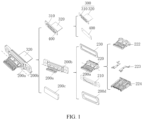
FIG. 1 is a schematic exploded view of a first connector according to an embodiment of this application; -
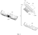
FIG. 2 is a schematic diagram of an overall structure of a first connector according to an embodiment of this application; -
FIG. 3 is a schematic diagram of an overall assembly of a first connector according to an embodiment of this application; -
FIG. 4 is a cross-sectional view of a first connector according to an embodiment of this application; -
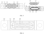
FIG. 5 is a schematic structural diagram of a socket base of a first connector according to an embodiment of this application; -
FIG. 6 is a schematic structural diagram after installation of a metal connection plate inFIG. 5 ; -
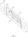
FIG. 7 is a schematic structural diagram of a base fixing portion of a first connector according to an embodiment of this application; -
FIG. 8 is an overall schematic diagram of a first connector from another perspective according to an embodiment of this application; -
FIG. 9 is a schematic structural diagram of a first connector without a housing according to an embodiment of this application; -
FIG. 10 is a schematic exploded view of a second connector according to an embodiment of this application; -
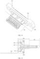
FIG. 11 is a schematic diagram of a second connector from a first perspective according to an embodiment of this application; -
FIG. 12 is a schematic structural diagram of a metal liner of a second connector according to an embodiment of this application; -
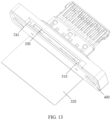
FIG. 13 is a schematic diagram of a second connector from a second perspective according to an embodiment of this application; -
FIG. 14 is a partial schematic diagram of a second connector according to an embodiment of this application; -
FIG. 15 is a cross-sectional view of a second connector according to an embodiment of this application; -
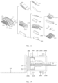
FIG. 16 is a schematic exploded view of a third connector according to an embodiment of this application; -
FIG. 17 is a cross-sectional view of a third connector according to an embodiment of this application; -
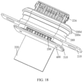
FIG. 18 is an overall diagram of a third connector from a first perspective according to an embodiment of this application; -
FIG. 19 is an overall diagram of a third connector from a second perspective according to an embodiment of this application; -
FIG. 20 is an overall schematic diagram of a fourth connector according to an embodiment of this application; and -
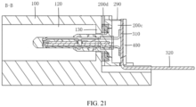
FIG. 21 is a cross-sectional view ofFIG. 20 along B-B. - Description of reference signs:
- 100. housing; 110. accommodating space; 120. insertion hole; 130. abutment protrusion;
- 200a. socket tongue; 201. second injection molding portion;
- 200b. socket base; 210. base fixing portion; 211. first groove; 212. first avoidance hole; 213. second groove; 214. third groove;
- 220. base main body; 221. first protrusion; 222. base body; 223. terminal partition plate; 224. terminal strip;
- 230. metal connection plate;
- 240. first injection molding portion; 241. fourth groove;
- 250. metal liner; 251. second avoidance hole;
- 260. cylindrical reinforcing member; 270. third injection molding portion; 280. metal connection member; 290. adhesive injection port;
- 200c. sealing adhesive;
- 200d. sealing ring; 200e. sealing ring mounting seat;
- 300. circuit board; 310. electrical connection sub-board; 320. circuit board main body; and
- 400. reinforcing plate.
- To make the objectives, technical solutions, and advantages of this application clearer, the following clearly and completely describes the technical solutions of this application with reference to specific embodiments of this application and corresponding accompanying drawings. Apparently, the described embodiments are merely some but not all of the embodiments of this application. All other embodiments obtained by persons of ordinary skill in the art based on the embodiments of this application without creative efforts fall within the protection scope of this application.
- The technical solutions disclosed in the embodiments of this application are described in detail below with reference to
FIGs. 1 to 21 . - Referring to
FIGs. 1 to 9 , an embodiment of this application discloses a connector, where the disclosed connector may be a Micro USB connector, a USB Type C connector, a Lightning connector, or the like. The disclosed connector includes ahousing 100, asocket tongue 200a, asocket base 200b, and acircuit board 300. - The
housing 100 is a foundation for mounting various components of the connector. Thehousing 100 is provided with anaccommodating space 110 and aninsertion hole 120 in communication with theaccommodating space 110; theinsertion hole 120 runs through a first end surface and a second end surface of thehousing 100; the first end surface is opposite the second end surface; and theaccommodating space 110 is arranged close to the second end surface. The first end surface may be an end into which an external plug extends when the external plug is in insertion fit with the connector. - A first end portion of the
socket tongue 200a extends into theinsertion hole 120 in a suspending manner. The external plug can enter through an opening of theinsertion hole 120 located on the first end surface to be electrically connected to thesocket tongue 200a. Thesocket base 200b is connected to a second end portion of thesocket tongue 200a, and thesocket base 200b is at least partially located in theaccommodating space 110. Thesocket base 200b seals an opening, located on the second end surface, of theinsertion hole 120, and thesocket base 200b has a first electrical connection portion arranged facing away from thesocket tongue 200a. - The
circuit board 300 is disposed in theaccommodating space 110, and thecircuit board 300 includes anelectrical connection sub-board 310. Theelectrical connection sub-board 310 is provided with a second electrical connection portion. A surface of theelectrical connection sub-board 310 provided with the second electrical connection portion is opposite the second end surface. The surface of theelectrical connection sub-board 310 provided with the second electrical connection portion may be parallel to the second end surface. Certainly, an included angle may be formed between the surface of theelectrical connection sub-board 310 provided with the second electrical connection portion and the second end surface, where the included angle is a small angle, for example, being less than 10 degrees or less than 5 degrees. Thesocket base 200b is located between thehousing 100 and theelectrical connection sub-board 310. The first electrical connection portion is electrically connected to the second electrical connection portion. Thesocket tongue 200a and thesocket base 200b may be electrically connected to thecircuit board 300 through the first electrical connection portion and the second electrical connection portion. - The connector disclosed in this embodiment of this application is configured to be a structure including the
housing 100, thesocket tongue 200a, thesocket base 200b, and the circuit board, so that thehousing 100 may be provided with theaccommodating space 110 and theinsertion hole 120 in communication with theaccommodating space 110. Theinsertion hole 120 can run through the first end surface and second end surface of thehousing 100, so that thesocket base 200b can seal the opening of theinsertion hole 120 located on the second end surface, thereby preventing external dirt such as dust from entering theaccommodating space 110 and protecting components in theaccommodating space 110. Thesocket base 200b is provided with the first electrical connection portion arranged facing away from thesocket tongue 200a. Theelectrical connection sub-board 310 is provided with the surface opposite the second end surface, so that the second electrical connection portion may be disposed on the surface of theelectrical connection sub-board 310 opposite the second end surface. Thus, this ensures the area of the surface required for provision of the second electrical connection portion in a case of ensuring the electrical connection stability between the first electrical connection portion and the second electrical connection portion, thereby ensuring the electrical connection stability between the first electrical connection portion and the second electrical connection portion without increasing the length of thesocket base 200b extending toward thecircuit board 300. As a result, the length of thesocket base 200b extending toward the circuit board can be reduced, so that the space occupied by the connector can be reduced, thereby solving the problem in the related art that the length of the socket tongue extending toward the circuit board is increased to ensure the electrical connection stability between the socket tongue and the circuit board, which otherwise causes a large space occupied by a socket. - The first electrical connection portion and the second electrical connection portion are electrically connected to each other, so the first electrical connection portion and the second electrical connection portion need to be sealed for waterproofness. To seal the first electrical connection portion and the second electrical connection portion, optionally, the
electrical connection sub-board 310 and thesocket base 200b can enclose theaccommodating space 110. Theaccommodating space 110 can be used for filling of a sealing adhesive 200c. The first electrical connection portion and the second electrical connection portion may be located in theaccommodating space 110. An electrical connection position between the first electrical connection portion and the second electrical connection portion is located in theaccommodating space 110. An adhesive injection port in communication with theaccommodating space 110 may be formed between theelectrical connection sub-board 310 and thesocket base 200b, or theelectrical connection sub-board 310 is provided with an adhesive injection port in communication with theaccommodating space 110, or thesocket base 200b is provided with an adhesive injection port in communication with theaccommodating space 110. - In this embodiment of this application, the positional relationship where the surface of the
electrical connection sub-board 310 provided with the second electrical connection portion is opposite the second end surface allows theelectrical connection sub-board 310 and thesocket base 200b to enclose theaccommodating space 110, so that the first electrical connection portion and the second electrical connection portion can be disposed in theaccommodating space 110. Thus, this allows theaccommodating space 110 to protect the first electrical connection portion and the second electrical connection portion and can provide a place for filling of the sealing adhesive 200c, thereby allowing the first electrical connection portion and the second electrical connection portion to be sealed by the sealing adhesive 200c after filling the sealing adhesive 200c into theaccommodating space 110 through the adhesive injection port. - Optionally, the sealing adhesive 200c can fill the
accommodating space 110 and cover the first electrical connection portion and the second electrical connection portion. Thesocket base 200b and theelectrical connection sub-board 310 are bonded and fixed by the sealing adhesive 200c. A side of thesocket base 200b facing away from thesocket tongue 200a is sealed and covered by the sealing adhesive 200c. - In this embodiment of this application, the sealing adhesive 200c fills the
accommodating space 110 and covers the first electrical connection portion and the second electrical connection portion, so that the first electrical connection portion and the second electrical connection portion can be sealed by the sealing adhesive 200c, thereby achieving waterproofness of the first electrical connection portion and the second electrical connection portion. Thesocket base 200b and theelectrical connection sub-board 310 are bonded and fixed by the sealing adhesive 200c, so that thesocket base 200b and theelectrical connection sub-board 310 can be connected to each other through the sealing adhesive 200c. The side of thesocket base 200b facing away from thesocket tongue 200a is sealed and covered by the sealing adhesive 200c, so that the sealing adhesive 200c can further seal the side of thesocket base 200b facing away from thesocket tongue 200a, thereby allowing thesocket base 200b to well seal theinsertion hole 120, and improving the waterproof performance of the connector. - In an optional embodiment, the
socket base 200b may include abase fixing portion 210 and a basemain body 220. Thebase fixing portion 210 may be connected to thehousing 100. Thesocket base 200b is connected to thehousing 100 through thebase fixing portion 210. Thebase fixing portion 210 may be provided with afirst groove 211 and afirst avoidance hole 212. An opening of thefirst groove 211 and thesocket tongue 200a may be respectively located on two sides of thesocket base 200b facing away from each other. Thefirst avoidance hole 212 may be formed in a bottom wall of thefirst groove 211. An end portion of the basemain body 220 facing away from thesocket tongue 200a is fixed in thefirst avoidance hole 212, thereby facilitating the installation of the basemain body 220 and thebase fixing portion 210. The end portion of the basemain body 220 facing away from thesocket tongue 200a may be detachably connected to thefirst avoidance hole 212. Certainly, the basemain body 220 and thebase fixing portion 210 may alternatively form an integrated structure. The basemain body 220 and thebase fixing portion 210 can together seal the opening of theinsertion hole 120 located on the second end face. The first electrical connection portion may be disposed on the basemain body 220, and the first electrical connection portion may be located in thefirst groove 211. The surface of theelectrical connection sub-board 310 provided with the second electrical connection portion can cover the opening of thefirst groove 211. The second electrical connection portion may be located in thefirst groove 211. A surface of thebase fixing portion 210 where thefirst groove 211 is formed may be a first surface. Theelectrical connection sub-board 310 and the first surface can enclose the accommodating space. - In this embodiment of this application, the
socket base 200b is configured to be a structure including thebase fixing portion 210 and the basemain body 220, so that thebase fixing portion 210 may be provided with thefirst groove 211, thereby allowing the surface of thebase fixing portion 210 where thefirst groove 211 is formed and theelectrical connection sub-board 310 to enclose theaccommodating space 110. Thebase fixing portion 210 is provided for forming thefirst groove 211 so as to enclose theaccommodating space 110 with theelectrical connection sub-board 310, thereby avoiding reduction in the strength of a component such as thehousing 100 or thecircuit board 300 due to the provision of a groove on the component such as thehousing 100 or thecircuit board 300 for enclosing theaccommodating space 110. - To allow for more stable connection between the
base fixing portion 210 and the basemain body 220, optionally, an edge of thebase fixing portion 210 enclosing thefirst avoidance hole 212 may be provided with asecond groove 213. The basemain body 220 may include afirst protrusion 221. Thefirst protrusion 221 may be in location fit with thesecond groove 213 in a circumferential direction of thefirst avoidance hole 212. The edge of thebase fixing portion 210 enclosing thefirst avoidance hole 212 is provided with thesecond groove 213, and the basemain body 220 is provided with thefirst protrusion 221, so that thefirst protrusion 221 is in location fit with thesecond groove 213 in the circumferential direction of thefirst avoidance hole 212, so as to limit the locations of thebase fixing portion 210 and the basemain body 220 in the circumferential direction of thefirst avoidance hole 212, thereby allowing for more stable connection between thebase fixing portion 210 and the basemain body 220. - Further, the edge of the
base fixing portion 210 enclosing thefirst avoidance hole 212 may be provided with athird groove 214. The basemain body 220 may include abase body 222 and aterminal partition plate 223 partially disposed in thebase body 222. Theterminal partition plate 223 can provide effects such as shielding magnetic fields and electric fields for thebase body 222 and aterminal strip 224 on thebase body 222. A portion of theterminal partition plate 223 protruding from thebase body 222 may be located in thethird groove 214. The portion of theterminal partition plate 223 protruding from thebase body 222 may be in location fit with thethird groove 214 in the circumferential direction of thefirst avoidance hole 212. Thebase body 222 may be a plastic component and may be formed by injection molding. - The portion of the
terminal partition plate 223 protruding from thebase body 222 may be in location fit with thethird groove 214 in the circumferential direction of thefirst avoidance hole 212, so that the connection stability between thebase fixing portion 210 and the basemain body 220 can be further improved. In addition, theterminal partition plate 223 is fully utilized, so that theterminal partition plate 223 not only has a shielding effect, but also has an effect of achieving location fit with thethird groove 214 in the circumferential direction of thefirst avoidance hole 212, thereby allowing theterminal partition plate 223 to have multiple functions. - To allow the base
main body 220 to be in limiting fit with thebase fixing portion 210 in a direction of the opening of thefirst groove 211, optionally, thesocket base 200b may further include ametal connection plate 230. Thebase fixing portion 210 may be a metal component. Themetal connection plate 230 may be connected to thebase fixing portion 210 through welding, and themetal connection plate 230 may be connected to theterminal partition plate 223 through welding. The basemain body 220 may be in limiting fit with themetal connection plate 230 in the direction of the opening of thefirst groove 211. Specifically, at least a portion of theterminal partition plate 223 and at least a portion of thefirst protrusion 221 can be clamped between thebase fixing portion 210 and themetal connection plate 230. Themetal connection plate 230 is welded to thebase fixing portion 210 and theterminal partition plate 223, so that the basemain body 220 is in limiting fit with thebase fixing portion 210 in the direction of the opening of thefirst groove 211, thereby improving the connection stability between the basemain body 220 and thebase fixing portion 210. - Optionally, a side wall of the
first groove 211 is provided with anadhesive injection port 290 in communication with thefirst groove 211, and theadhesive injection port 290 may be in communication with theaccommodating space 110. Thefirst groove 211 of thebase fixing portion 210 is provided with theadhesive injection port 290, helping to fill the sealing adhesive 200c into theaccommodating space 110, and avoiding the provision of theadhesive injection port 290 in thehousing 100 or thecircuit board 300, thereby allowing for high strength of thehousing 100 or thecircuit board 300. - Referring to
FIGs. 10 to 15 , an embodiment of this application discloses a connector, where the disclosed connector may be a Micro USB connector, a USB Type C connector, a Lightning connector, or the like. The disclosed connector includes ahousing 100, asocket tongue 200a, asocket base 200b, and acircuit board 300. - The
housing 100 is a foundation for mounting various components of the connector. Thehousing 100 is provided with anaccommodating space 110 and aninsertion hole 120 in communication with theaccommodating space 110; theinsertion hole 120 runs through a first end surface and a second end surface of thehousing 100; the first end surface is opposite the second end surface; and theaccommodating space 110 is arranged close to the second end surface. The first end surface may be an end into which an external plug extends when the external plug is in insertion fit with the connector. - A first end portion of the
socket tongue 200a extends into theinsertion hole 120 in a suspending manner. The external plug can enter through an opening of theinsertion hole 120 located on the first end surface to be electrically connected to thesocket tongue 200a. Thesocket base 200b is connected to a second end portion of thesocket tongue 200a, and thesocket base 200b is at least partially located in theaccommodating space 110. Thesocket base 200b seals an opening, located on the second end surface, of theinsertion hole 120, and thesocket base 200b has a first electrical connection portion arranged facing away from thesocket tongue 200a. - The
circuit board 300 is disposed in theaccommodating space 110, and thecircuit board 300 includes anelectrical connection sub-board 310. Theelectrical connection sub-board 310 is provided with a second electrical connection portion. A surface of theelectrical connection sub-board 310 provided with the second electrical connection portion is opposite the second end surface. The surface of theelectrical connection sub-board 310 provided with the second electrical connection portion may be parallel to the second end surface. Certainly, an included angle may be formed between the surface of theelectrical connection sub-board 310 provided with the second electrical connection portion and the second end surface, where the included angle is a small angle, for example, being less than 10 degrees or less than 5 degrees. Thesocket base 200b is located between thehousing 100 and theelectrical connection sub-board 310. The first electrical connection portion is electrically connected to the second electrical connection portion. Thesocket tongue 200a and thesocket base 200b may be electrically connected to thecircuit board 300 through the first electrical connection portion and the second electrical connection portion. - The connector disclosed in this embodiment of this application is configured to be a structure including the
housing 100, thesocket tongue 200a, thesocket base 200b, and the circuit board, so that thehousing 100 may be provided with theaccommodating space 110 and theinsertion hole 120 in communication with theaccommodating space 110. Theinsertion hole 120 can run through the first end surface and second end surface of thehousing 100, so that thesocket base 200b can seal the opening of theinsertion hole 120 located on the second end surface, thereby preventing external dirt such as dust from entering theaccommodating space 110 and protecting components in theaccommodating space 110. Thesocket base 200b is provided with the first electrical connection portion arranged facing away from thesocket tongue 200a. Theelectrical connection sub-board 310 is provided with the surface opposite the second end surface, so that the second electrical connection portion may be disposed on the surface of theelectrical connection sub-board 310 opposite the second end surface. Thus, this ensures the area of the surface required for provision of the second electrical connection portion in a case of ensuring the electrical connection stability between the first electrical connection portion and the second electrical connection portion, thereby ensuring the electrical connection stability between the first electrical connection portion and the second electrical connection portion without increasing the length of thesocket base 200b extending toward thecircuit board 300. As a result, the length of thesocket base 200b extending toward the circuit board can be reduced, so that the space occupied by the connector can be reduced, thereby solving the problem in the related art that the length of the socket tongue extending toward the circuit board is increased to ensure the electrical connection stability between the socket tongue and the circuit board, which otherwise causes a large space occupied by a socket. - The first electrical connection portion and the second electrical connection portion are electrically connected to each other, so the first electrical connection portion and the second electrical connection portion need to be sealed for waterproofness. To seal the first electrical connection portion and the second electrical connection portion, optionally, the
electrical connection sub-board 310 and thesocket base 200b can enclose theaccommodating space 110. Theaccommodating space 110 can be used for filling of a sealing adhesive 200c. The first electrical connection portion and the second electrical connection portion may be located in theaccommodating space 110. An electrical connection position between the first electrical connection portion and the second electrical connection portion is located in theaccommodating space 110. An adhesive injection port in communication with theaccommodating space 110 may be formed between theelectrical connection sub-board 310 and thesocket base 200b, or theelectrical connection sub-board 310 is provided with an adhesive injection port in communication with theaccommodating space 110, or thesocket base 200b is provided with an adhesive injection port in communication with theaccommodating space 110. - In this embodiment of this application, the positional relationship where the surface of the
electrical connection sub-board 310 provided with the second electrical connection portion is opposite the second end surface allows theelectrical connection sub-board 310 and thesocket base 200b to enclose theaccommodating space 110, so that the first electrical connection portion and the second electrical connection portion can be disposed in theaccommodating space 110. Thus, this allows theaccommodating space 110 to protect the first electrical connection portion and the second electrical connection portion and can provide a place for filling of the sealing adhesive 200c, thereby allowing the first electrical connection portion and the second electrical connection portion to be sealed by the sealing adhesive 200c after filling the sealing adhesive 200c into theaccommodating space 110 through the adhesive injection port. - In an optional embodiment, the
socket base 200b may include a firstinjection molding portion 240. Thesocket tongue 200a may include a secondinjection molding portion 201. The firstinjection molding portion 240 and the secondinjection molding portion 201 may form an integrated injection molding structure. The firstinjection molding portion 240 may be connected to thehousing 100, and the firstinjection molding portion 240 may be provided with afourth groove 241. An opening of thefourth groove 241 and thesocket tongue 200a are respectively located on two sides of thesocket base 200b facing away from each other. The first electrical connection portion is disposed on the firstinjection molding portion 240 and located in thefourth groove 241. The surface of theelectrical connection sub-board 310 provided with the second electrical connection portion can cover the opening of thefourth groove 241. The second electrical connection portion may be located in thefourth groove 241. A surface of the firstinjection molding portion 240 where thefourth groove 241 is formed may be a second surface. Theelectrical connection sub-board 310 and the second surface can enclose theaccommodating space 110. The firstinjection molding portion 240 or theelectrical connection sub-board 310 may be provided with theadhesive injection port 290 in communication with theaccommodating space 110. - In this embodiment of this application, the
socket base 200b is configured to include the firstinjection molding portion 240, and thesocket tongue 200a is configured to include the secondinjection molding portion 201, so that the firstinjection molding portion 240 and the secondinjection molding portion 201 form the integrated injection molding structure. Thus, this can improve the overall strength of thesocket base 200b and thesocket tongue 200a, thereby allowing the firstinjection molding portion 240 to still have high strength after the provision of thefourth groove 241 on the firstinjection molding portion 240. The surface of the firstinjection molding portion 240 where thefourth groove 241 is formed may be the second surface and encloses theaccommodating space 110 together with theelectrical connection sub-board 310, so that the first electrical connection portion and the second electrical connection portion may be located in the accommodating space, thereby protecting the first electrical connection portion and the second electrical connection portion, and helping to fill the sealing adhesive 200c into theaccommodating space 110. - To further improve the strength of the
socket base 200b, optionally, thefourth groove 241 may be a through groove. Thesocket base 200b may further include ametal liner 250, where themetal liner 250 may be connected to the firstinjection molding portion 240 through injection molding, themetal liner 250 may be at least partially disposed in thefourth groove 241, and themetal liner 250 may be provided with asecond avoidance hole 251. The first electrical connection portion can pass through thesecond avoidance hole 251 to extend into the accommodating space. Theelectrical connection sub-board 310 and a first port of thefourth groove 241 may enclose a first orifice, and themetal liner 250 can seal the first orifice. Theelectrical connection sub-board 310 and a second port of thefourth groove 241 may enclose a second orifice, and the second orifice may be theadhesive injection port 290 in communication with the accommodating space. - The
metal liner 250 is provided, themetal liner 250 may be connected to the firstinjection molding portion 240 through injection molding, and themetal liner 250 may be at least partially disposed in thefourth groove 241, so that themetal liner 250 can further improve the strength of thesocket base 200b. Thefourth groove 241 is configured to be a through groove, facilitating processing, thereby allowing themetal liner 250 to seal the first orifice enclosed by theelectrical connection sub-board 310 and the first port of thefourth groove 241. Theelectrical connection sub-board 310 and the second port of thefourth groove 241 enclose theadhesive injection port 290 in communication with the accommodating space, thereby helping to fill the sealing adhesive 200c into theaccommodating space 110. - Referring to
FIGs. 16 to 19 , an embodiment of this application discloses a connector, where the disclosed connector may be a Micro USB connector, a USB Type C connector, a Lightning connector, or the like. The disclosed connector includes ahousing 100, asocket tongue 200a, asocket base 200b, and acircuit board 300. - The
housing 100 is a foundation for mounting various components of the connector. Thehousing 100 is provided with anaccommodating space 110 and aninsertion hole 120 in communication with theaccommodating space 110; theinsertion hole 120 runs through a first end surface and a second end surface of thehousing 100; the first end surface is opposite the second end surface; and theaccommodating space 110 is arranged close to the second end surface. The first end surface may be an end into which an external plug extends when the external plug is in insertion fit with the connector. - A first end portion of the
socket tongue 200a extends into theinsertion hole 120 in a suspending manner. The external plug can enter through an opening of theinsertion hole 120 located on the first end surface to be electrically connected to thesocket tongue 200a. Thesocket base 200b is connected to a second end portion of thesocket tongue 200a, and thesocket base 200b is at least partially located in theaccommodating space 110. Thesocket base 200b seals an opening, located on the second end surface, of theinsertion hole 120, and thesocket base 200b has a first electrical connection portion arranged facing away from thesocket tongue 200a. - The
circuit board 300 is disposed in theaccommodating space 110, and thecircuit board 300 includes anelectrical connection sub-board 310. Theelectrical connection sub-board 310 is provided with a second electrical connection portion. A surface of theelectrical connection sub-board 310 provided with the second electrical connection portion is opposite the second end surface. The surface of theelectrical connection sub-board 310 provided with the second electrical connection portion may be parallel to the second end surface. Certainly, an included angle may be formed between the surface of theelectrical connection sub-board 310 provided with the second electrical connection portion and the second end surface, where the included angle is a small angle, for example, being less than 10 degrees or less than 5 degrees. Thesocket base 200b is located between thehousing 100 and theelectrical connection sub-board 310. The first electrical connection portion is electrically connected to the second electrical connection portion. Thesocket tongue 200a and thesocket base 200b may be electrically connected to thecircuit board 300 through the first electrical connection portion and the second electrical connection portion. - The connector disclosed in this embodiment of this application is configured to be a structure including the
housing 100, thesocket tongue 200a, thesocket base 200b, and the circuit board, so that thehousing 100 may be provided with theaccommodating space 110 and theinsertion hole 120 in communication with theaccommodating space 110. Theinsertion hole 120 can run through the first end surface and second end surface of thehousing 100, so that thesocket base 200b can seal the opening of theinsertion hole 120 located on the second end surface, thereby preventing external dirt such as dust from entering theaccommodating space 110 and protecting components in theaccommodating space 110. Thesocket base 200b is provided with the first electrical connection portion arranged facing away from thesocket tongue 200a. Theelectrical connection sub-board 310 is provided with the surface opposite the second end surface, so that the second electrical connection portion may be disposed on the surface of theelectrical connection sub-board 310 opposite the second end surface. Thus, this ensures the area of the surface required for provision of the second electrical connection portion in a case of ensuring the electrical connection stability between the first electrical connection portion and the second electrical connection portion, thereby ensuring the electrical connection stability between the first electrical connection portion and the second electrical connection portion without increasing the length of thesocket base 200b extending toward thecircuit board 300. As a result, the length of thesocket base 200b extending toward the circuit board can be reduced, so that the space occupied by the connector can be reduced, thereby solving the problem in the related art that the length of the socket tongue extending toward the circuit board is increased to ensure the electrical connection stability between the socket tongue and the circuit board, which otherwise causes a large space occupied by a socket. - The first electrical connection portion and the second electrical connection portion are electrically connected to each other, so the first electrical connection portion and the second electrical connection portion need to be sealed for waterproofness. To seal the first electrical connection portion and the second electrical connection portion, optionally, the
electrical connection sub-board 310 and thesocket base 200b can enclose theaccommodating space 110. Theaccommodating space 110 can be used for filling of a sealing adhesive 200c. The first electrical connection portion and the second electrical connection portion may be located in theaccommodating space 110. An electrical connection position between the first electrical connection portion and the second electrical connection portion is located in theaccommodating space 110. An adhesive injection port in communication with theaccommodating space 110 may be formed between theelectrical connection sub-board 310 and thesocket base 200b, or theelectrical connection sub-board 310 is provided with an adhesive injection port in communication with theaccommodating space 110, or thesocket base 200b is provided with an adhesive injection port in communication with theaccommodating space 110. - In this embodiment of this application, the positional relationship where the surface of the
electrical connection sub-board 310 provided with the second electrical connection portion is opposite the second end surface allows theelectrical connection sub-board 310 and thesocket base 200b to enclose theaccommodating space 110, so that the first electrical connection portion and the second electrical connection portion can be disposed in theaccommodating space 110. Thus, this allows theaccommodating space 110 to protect the first electrical connection portion and the second electrical connection portion and can provide a place for filling of the sealing adhesive 200c, thereby allowing the first electrical connection portion and the second electrical connection portion to be sealed by the sealing adhesive 200c after filling the sealing adhesive 200c into theaccommodating space 110 through the adhesive injection port. - In an optional embodiment, the
socket base 200b may include a cylindrical reinforcingmember 260 and a thirdinjection molding portion 270. The thirdinjection molding portion 270 may be at least partially disposed in thecylindrical reinforcing member 260. The cylindrical reinforcingmember 260 may be provided with an avoidance notch. The thirdinjection molding portion 270 may be provided with a fifth groove. An opening of the fifth groove and thesocket tongue 200a may be located on two sides of thesocket base 200b facing away from each other. The first electrical connection portion may be disposed on the thirdinjection molding portion 270 and located in the fifth groove. The surface of theelectrical connection sub-board 310 provided with the second electrical connection portion can cover the opening of the fifth groove. The second electrical connection portion may be located in the fifth groove. A surface of the thirdinjection molding portion 270 where the fifth groove is formed may be a third surface. Theelectrical connection sub-board 310 and the third surface can enclose theaccommodating space 110. Theelectrical connection sub-board 310 and the avoidance notch can enclose theadhesive injection port 290. Theadhesive injection port 290 may be in communication with the accommodating space. - In this embodiment of this application, the
socket base 200b is configured to include the cylindrical reinforcingmember 260 and the thirdinjection molding portion 270, so that the thirdinjection molding portion 270 may be at least partially disposed in thecylindrical reinforcing member 260. The cylindrical reinforcingmember 260 can protect the thirdinjection molding portion 270 and can reinforce theoverall socket base 200b. The thirdinjection molding portion 270 is provided with the fifth groove, so that the first electrical connection portion and the second electrical connection portion may be disposed in the fifth groove. Thus, theelectrical connection sub-board 310 and the third surface being the surface of the thirdinjection molding portion 270 where the fifth groove is formed can enclose theaccommodating space 110, so that the first electrical connection portion and the second electrical connection portion may be disposed in theaccommodating space 110, thereby sealing the first electrical connection portion and the second electrical connection portion after filling the sealing adhesive 200 through theadhesive injection port 290 enclosed by theelectrical connection sub-board 310 and the avoidance notch. - To facilitate the connection between the cylindrical reinforcing
member 260 and the thirdinjection molding portion 270, optionally, thecylindrical reinforcing member 260 may be a metal structural member. Thesocket base 200b may further include ametal connection member 280, where themetal connection member 280 may be connected to the thirdinjection molding portion 270 through injection molding, and themetal connection member 280 may be connected to the cylindrical reinforcingmember 260 through welding. Themetal connection member 280 is provided, and the cylindrical reinforcingmember 260 is configured to be the metal structural member, so that themetal connection member 280 may be connected to the thirdinjection molding portion 270 through injection molding, and themetal connection member 280 may be connected to the cylindrical reinforcingmember 260 through welding, thereby facilitating the connection between the cylindrical reinforcingmember 260 and the thirdinjection molding portion 270. - Optionally, the connector may include a
base fixing portion 210. Thebase fixing portion 210 may fit around thecylindrical reinforcing member 260. The cylindrical reinforcingmember 260 may be connected to thehousing 100 through thebase fixing portion 210. - In some embodiments, the
circuit board 300 may be a flexible circuit board. Thecircuit board 300 may further include a circuit boardmain body 320. Theelectrical connection sub-board 310 may be perpendicular to the circuit boardmain body 320 and forms a bent structure. Thecircuit board 300 is configured to be the flexible circuit board, and thecircuit board 300 may further include the circuit boardmain body 320, so that theelectrical connection sub-board 310 may be perpendicular to the circuit boardmain body 320 and forms the bent structure, thereby facilitating the arrangement of thecircuit board 300 and the thinning of an electronic device when the connector is disposed in the electronic device. - Optionally, the
electrical connection sub-board 310 may be perpendicular to thesocket tongue 200a. Theelectrical connection sub-board 310 is configured to be perpendicular to thesocket tongue 200a, so that an entirety formed by theelectrical connection sub-board 310 and thesocket tongue 200a is relatively neat, thereby facilitating the assembly with other devices. - To improve the connection strength between the
electrical connection sub-board 310 and thesocket base 200b, optionally, the connector may further include a reinforcingplate 400. The reinforcingplate 400 may be attached to a second board surface of theelectrical connection sub-board 310 facing away from thesocket base 200b, and the reinforcingplate 400 may be connected to thesocket base 200b. In an embodiment where thesocket base 200b includes abase fixing portion 210 and a basemain body 220, the reinforcingplate 400 may be connected to thebase fixing portion 210. The provision of the reinforcingplate 400 provided allows for higher connection strength between theelectrical connection sub-board 310 and thesocket base 200b. - Optionally, the connector may further include a
sealing ring 200d. The sealingring 200d may be arranged around thesocket tongue 200a and may be clamped and fixed between the second end surface and thesocket base 200b. Thesocket base 200b may be in sealing fit with the second end surface through thesealing ring 200d, thereby improving the sealing of thesocket base 200b on the opening of theinsertion hole 120 located on the second end surface. - The connector may further include a sealing
ring mounting seat 200e. The sealingring mounting seat 200e may be mounted on thecylindrical reinforcing member 260. The sealingring 200d may be mounted on the sealingring mounting seat 200e. - In some embodiments, since the
socket base 200b seals the opening of theinsertion hole 120 located on the second end surface, when the external plug is plugged into the opening of theinsertion hole 120 located on the first end surface, an end portion of the external plug can abut against thesocket base 200b, thereby limiting the movement of the external plug. - To avoid the loosening of the connection between the
socket base 200b and thehousing 100 due to the frequent abutment of the end portion of the external plug against thesocket base 200b, optionally, referring toFIGs. 20 and21 , thehousing 100 may be provided with anabutment protrusion 130. Theabutment protrusion 130 may be disposed in theinsertion hole 120 and located adjacent to the second end surface. Theabutment protrusion 130 is configured to abut against the end portion of the external plug so as to limit the external plug when the external plug is inserted into the insertion hole. With theabutment protrusion 130 provided, theabutment protrusion 130 can abut against the end portion of the external plug to limit the external plug when the external plug is inserted into the insertion hole, thereby avoiding the abutment of the end portion of the external plug against thesocket base 200b, and solving the problem of the loosening of the connection between thesocket base 200b and thehousing 100 due to the frequent abutment of the end portion of the external plug against thesocket base 200b. - This application further discloses an electronic device. The disclosed electronic device includes the connector according to the foregoing embodiments. The electronic device disclosed in the embodiments of this application uses the connector according to the foregoing embodiments. Since the connector according to the foregoing embodiments can reduce the occupied space, the space occupied by the connector in the electronic device is relatively reduced. This is conducive to lightness and thinness of the electronic device and can also provide more installation space for other components of the electronic device.
- The electronic device disclosed in the embodiments of this application may be a mobile phone, a tablet, a game console, or the like.
- The foregoing embodiments of this application focus on the differences between the embodiments. As long as the different features of improvement in the embodiments are not contradictory, they can be combined to form a more preferred embodiment. For brevity, details are not repeated here.
- The foregoing describes the embodiments of this application with reference to the accompanying drawings. However, this application is not limited to the foregoing specific implementations. The foregoing specific implementations are merely illustrative rather than restrictive. Inspired by this application, persons of ordinary skill in the art may develop many other forms without departing from the essence of this application and the protection scope of the claims, and all such forms shall fall within the protection scope of this application.
Claims (14)
- A connector, comprising a housing (100), a socket tongue (200a), a socket base (200b), and a circuit board (300), whereinthe housing (100) is provided with an accommodating space (110) and an insertion hole (120) in communication with the accommodating space (110); the insertion hole (120) runs through a first end surface and a second end surface of the housing (100); the first end surface is opposite the second end surface; and the accommodating space (110) is arranged close to the second end surface;a first end portion of the socket tongue (200a) extends into the insertion hole (120) in a suspending manner; and the socket base (200b) is connected to a second end portion of the socket tongue (200a), the socket base (200b) is at least partially located in the accommodating space (110), the socket base (200b) seals an opening, located on the second end surface, of the insertion hole (120), and the socket base (200b) has a first electrical connection portion arranged facing away from the socket tongue (200a); andthe circuit board (300) is disposed in the accommodating space (110), and the circuit board (300) comprises an electrical connection sub-board (310); the electrical connection sub-board (310) is provided with a second electrical connection portion; a surface of the electrical connection sub-board (310) provided with the second electrical connection portion is opposite the second end surface; the socket base (200b) is located between the housing (100) and the electrical connection sub-board (310); and the first electrical connection portion is electrically connected to the second electrical connection portion.
- The connector according to claim 1, wherein the electrical connection sub-board (310) and the socket base (200b) enclose the accommodating space (110); the accommodating space (110) is used for filling of a sealing adhesive (200c); the first electrical connection portion and the second electrical connection portion are located in the accommodating space (110); and an adhesive injection port (290) in communication with the accommodating space (110) is formed between the electrical connection sub-board (310) and the socket base (200b); or
the electrical connection sub-board (310) or the socket base (200b) is provided with an adhesive injection port (290) in communication with the accommodating space (110). - The connector according to claim 2, wherein the sealing adhesive (200c) fills the accommodating space (110) and covers the first electrical connection portion and the second electrical connection portion; the socket base (200b) and the electrical connection sub-board (310) are bonded and fixed by the sealing adhesive (200c); and a side of the socket base (200b) facing away from the socket tongue (200a) is sealed and covered by the sealing adhesive (200c).
- The connector according to claim 1, wherein the socket base (200b) comprises a base fixing portion (210) and a base main body (220);the base fixing portion (210) is connected to the housing (100), and the base fixing portion (210) is provided with a first groove (211) and a first avoidance hole (212); an opening of the first groove (211) and the socket tongue (200a) are respectively located on two sides of the socket base (200b) facing away from each other; the first avoidance hole (212) is formed in a bottom wall of the first groove (211); an end portion of the base main body (220) facing away from the socket tongue (200a) is fixed in the first avoidance hole (212); and the first electrical connection portion is disposed on the base main body (220), and the first electrical connection portion is located in the first groove (211); andthe surface of the electrical connection sub-board (310) provided with the second electrical connection portion covers the opening of the first groove (211); the second electrical connection portion is located in the first groove (211); a surface of the base fixing portion (210) where the first groove (211) is formed is a first surface; and the electrical connection sub-board (310) and the first surface enclose the accommodating space (110).
- The connector according to claim 4, wherein an edge of the base fixing portion (210) enclosing the first avoidance hole (212) is provided with a second groove (213); the base main body (220) comprises a first protrusion (221); and the first protrusion (221) is in location fit with the second groove (213) in a circumferential direction of the first avoidance hole (212).
- The connector according to claim 4 or 5, wherein the edge of the base fixing portion (210) enclosing the first avoidance hole (212) is provided with a third groove (214); the base main body (220) comprises a base body (222) and a terminal partition plate (223) partially disposed in the base body (222); and a portion of the terminal partition plate (223) protruding from the base body (222) is in location fit with the third groove (214) in the circumferential direction of the first avoidance hole (212).
- The connector according to claim 6, wherein the socket base (200b) further comprises a metal connection plate (230); the base fixing portion (210) is a metal component; the metal connection plate (230) is connected to the base fixing portion (210) through welding, and the metal connection plate (230) is connected to the terminal partition plate (223) through welding; and the base main body (220) is in limiting fit with the metal connection plate (230) in a direction of the opening of the first groove (211).
- The connector according to claim 4, wherein a side wall of the first groove (211) is provided with an adhesive injection port (290) in communication with the first groove (211); and the adhesive injection port (290) is in communication with the accommodating space.
- The connector according to claim 2, wherein the socket base (200b) comprises a first injection molding portion (240); the socket tongue (200a) comprises a second injection molding portion (201); and the first injection molding portion (240) and the second injection molding portion (201) form an integrated injection molding structure;the first injection molding portion (240) is connected to the housing (100), and the first injection molding portion (240) is provided with a fourth groove (241); an opening of the fourth groove (241) and the socket tongue (200a) are respectively located on two sides of the socket base (200b) facing away from each other; and the first electrical connection portion is disposed on the first injection molding portion (240) and located in the fourth groove (241); andthe surface of the electrical connection sub-board (310) provided with the second electrical connection portion covers the opening of the fourth groove (241); the second electrical connection portion is located in the fourth groove (241); a surface of the first injection molding portion (240) where the fourth groove (241) is formed is a second surface; and the electrical connection sub-board (310) and the second surface enclose the accommodating space (110).
- The connector according to claim 9, wherein the fourth groove (241) is a through groove; the socket base (200b) further comprises a metal liner (250); the metal liner (250) is connected to the first injection molding portion (240) through injection molding, the metal liner (250) is at least partially disposed in the fourth groove (241), and the metal liner (250) is provided with a second avoidance hole (251); and the first electrical connection portion passes through the second avoidance hole (251) to extend into the accommodating space (110);the electrical connection sub-board (310) and a first port of the fourth groove (241) enclose a first orifice, and the metal liner (250) seals the first orifice; andthe electrical connection sub-board (310) and a second port of the fourth groove (241) enclose a second orifice, and the second orifice is the adhesive injection port (290) in communication with the accommodating space.
- The connector according to claim 2, wherein the socket base (200b) comprises a cylindrical reinforcing member (260) and a third injection molding portion (270); the third injection molding portion (270) is at least partially disposed in the cylindrical reinforcing member (260); the cylindrical reinforcing member (260) is provided with an avoidance notch; the third injection molding portion (270) is provided with a fifth groove; an opening of the fifth groove and the socket tongue (200a) are located on two sides of the socket base (200b) facing away from each other; and the first electrical connection portion is disposed on the third injection molding portion (270) and located in the fifth groove; and
the surface of the electrical connection sub-board (310) provided with the second electrical connection portion covers the opening of the fifth groove; the second electrical connection portion is located in the fifth groove; a surface of the third injection molding portion (270) where the fifth groove is formed is a third surface; the electrical connection sub-board (310) and the third surface enclose the accommodating space (110); the electrical connection sub-board (310) and the avoidance notch enclose the adhesive injection port (290); and the adhesive injection port is in communication with the accommodating space (110). - The connector according to claim 11, wherein the cylindrical reinforcing member (260) is a metal structural member; and the socket base (200b) further comprises a metal connection member (280), wherein the metal connection member (280) is connected to the third injection molding portion (270) through injection molding, and the metal connection member (280) is connected to the cylindrical reinforcing member (260) through welding.
- The connector according to claim 1, wherein the circuit board (300) is a flexible circuit board, and the circuit board (300) further comprises a circuit board main body (320); and the electrical connection sub-board (310) is perpendicular to the circuit board main body (320) and forms a bent structure; and/or
the electrical connection sub-board (310) is perpendicular to the socket tongue (200a). - An electronic device, comprising the connector according to any one of claims 1 to 13.
Applications Claiming Priority (2)
| Application Number | Priority Date | Filing Date | Title |
|---|---|---|---|
| CN202211178600.8A CN115473072B (en) | 2022-09-26 | 2022-09-26 | Connectors and electronic devices |
| PCT/CN2023/121165 WO2024067504A1 (en) | 2022-09-26 | 2023-09-25 | Connector and electronic device |
Publications (2)
| Publication Number | Publication Date |
|---|---|
| EP4576444A1 true EP4576444A1 (en) | 2025-06-25 |
| EP4576444A4 EP4576444A4 (en) | 2025-11-05 |
Family
ID=84335266
Family Applications (1)
| Application Number | Title | Priority Date | Filing Date |
|---|---|---|---|
| EP23870734.3A Pending EP4576444A4 (en) | 2022-09-26 | 2023-09-25 | CONNECTOR AND ELECTRONIC DEVICE |
Country Status (4)
| Country | Link |
|---|---|
| US (1) | US20250219335A1 (en) |
| EP (1) | EP4576444A4 (en) |
| CN (1) | CN115473072B (en) |
| WO (1) | WO2024067504A1 (en) |
Families Citing this family (3)
| Publication number | Priority date | Publication date | Assignee | Title |
|---|---|---|---|---|
| CN115473072B (en) * | 2022-09-26 | 2026-03-17 | 维沃移动通信有限公司 | Connectors and electronic devices |
| CN116247463A (en) * | 2023-03-23 | 2023-06-09 | 维沃移动通信有限公司 | Connectors and Electronics |
| CN116667040B (en) * | 2023-06-21 | 2025-12-30 | 维沃移动通信有限公司 | Connectors and electronic devices |
Family Cites Families (16)
| Publication number | Priority date | Publication date | Assignee | Title |
|---|---|---|---|---|
| TW540880U (en) * | 2001-12-26 | 2003-07-01 | Hon Hai Prec Ind Co Ltd | Electrical connector |
| TWI466401B (en) * | 2011-06-17 | 2014-12-21 | Molex Inc | A plug device, a socket device, and combinations thereof |
| TWM501018U (en) * | 2014-12-04 | 2015-05-11 | Lotes Co Ltd | Electrical connector |
| CN104733950B (en) * | 2015-03-09 | 2024-03-29 | 连展科技(深圳)有限公司 | Waterproof socket electric connector |
| CN106571556B (en) * | 2015-10-12 | 2019-04-26 | 富士康(昆山)电脑接插件有限公司 | Electric connector and its manufacturing method |
| CN109643862A (en) * | 2016-08-12 | 2019-04-16 | 蔡周贤 | Front-back two-sided electric connector |
| CN206742538U (en) * | 2017-05-22 | 2017-12-12 | 上海莫仕连接器有限公司 | Electric connector |
| US9997866B1 (en) * | 2017-11-24 | 2018-06-12 | Cheng Uei Precision Industry Co., Ltd. | Waterproof connector |
| CN109038000B (en) * | 2018-08-13 | 2020-09-25 | 昆山杰顺通精密组件有限公司 | Positive reverse plug USB socket |
| CN209056690U (en) * | 2018-09-30 | 2019-07-02 | 苏州华旃航天电器有限公司 | A kind of closed type adapter |
| CN209233042U (en) * | 2018-12-18 | 2019-08-09 | 江西联创宏声电子股份有限公司 | USB sockets and electronics |
| CN211556202U (en) * | 2020-03-27 | 2020-09-22 | 维沃移动通信有限公司 | Connector sockets and electronic equipment |
| TWI824267B (en) * | 2020-12-15 | 2023-12-01 | 大陸商東莞立德精密工業有限公司 | Charging adapter device and installation method thereof |
| CN113518524B (en) * | 2021-04-19 | 2022-12-13 | 维沃移动通信有限公司 | Electronic device |
| CN215645216U (en) * | 2021-08-30 | 2022-01-25 | 安费诺电子装配(厦门)有限公司 | Cable connector and connector assembly |
| CN115473072B (en) * | 2022-09-26 | 2026-03-17 | 维沃移动通信有限公司 | Connectors and electronic devices |
-
2022
- 2022-09-26 CN CN202211178600.8A patent/CN115473072B/en active Active
-
2023
- 2023-09-25 EP EP23870734.3A patent/EP4576444A4/en active Pending
- 2023-09-25 WO PCT/CN2023/121165 patent/WO2024067504A1/en not_active Ceased
-
2025
- 2025-03-17 US US19/082,138 patent/US20250219335A1/en active Pending
Also Published As
| Publication number | Publication date |
|---|---|
| EP4576444A4 (en) | 2025-11-05 |
| WO2024067504A1 (en) | 2024-04-04 |
| CN115473072A (en) | 2022-12-13 |
| CN115473072B (en) | 2026-03-17 |
| US20250219335A1 (en) | 2025-07-03 |
Similar Documents
| Publication | Publication Date | Title |
|---|---|---|
| US20250219335A1 (en) | Connector and electronic device | |
| US6227872B1 (en) | Moisture resistant electrical connector for a cellular telephone | |
| US9401568B1 (en) | Connecting device and electronic device | |
| KR20150027096A (en) | Electric connector | |
| JP3817489B2 (en) | Receptacle electrical connector | |
| WO2022268017A1 (en) | Electronic device | |
| JP4916388B2 (en) | Portable electronic devices | |
| CN111916483B (en) | Display screen body assembly | |
| EP4138527B1 (en) | Terminal device | |
| CN218849684U (en) | Terminal device | |
| JP2013106196A (en) | Portable terminal | |
| CN111082248B (en) | a mobile terminal | |
| CN215497298U (en) | USB socket and electronic equipment | |
| CN215989386U (en) | Electrical connector | |
| CN220585654U (en) | USB connector | |
| CN221410431U (en) | Aerosol generating device and battery compartment structure thereof | |
| CN222507879U (en) | Battery and battery cover integrated assembly and mobile phone | |
| CN216624683U (en) | USB seat mounting structure | |
| CN223942159U (en) | Power adapter | |
| CN212934995U (en) | Dust-proof USB connector | |
| CN116470334A (en) | Electrical Connectors and Electronic Devices | |
| CN220605132U (en) | Connector with a plurality of connectors | |
| CN214490645U (en) | Robot joint structure and robot | |
| CN216598043U (en) | Interface member, connector assembly, printed circuit board assembly, and battery assembly | |
| CN214313691U (en) | Electrical connector |
Legal Events
| Date | Code | Title | Description |
|---|---|---|---|
| STAA | Information on the status of an ep patent application or granted ep patent |
Free format text: STATUS: THE INTERNATIONAL PUBLICATION HAS BEEN MADE |
|
| PUAI | Public reference made under article 153(3) epc to a published international application that has entered the european phase |
Free format text: ORIGINAL CODE: 0009012 |
|
| STAA | Information on the status of an ep patent application or granted ep patent |
Free format text: STATUS: REQUEST FOR EXAMINATION WAS MADE |
|
| 17P | Request for examination filed |
Effective date: 20250319 |
|
| AK | Designated contracting states |
Kind code of ref document: A1 Designated state(s): AL AT BE BG CH CY CZ DE DK EE ES FI FR GB GR HR HU IE IS IT LI LT LU LV MC ME MK MT NL NO PL PT RO RS SE SI SK SM TR |
|
| A4 | Supplementary search report drawn up and despatched |
Effective date: 20251009 |
|
| RIC1 | Information provided on ipc code assigned before grant |
Ipc: H01R 13/46 20060101AFI20251002BHEP Ipc: H01R 13/52 20060101ALI20251002BHEP Ipc: H04M 1/02 20060101ALI20251002BHEP Ipc: H01R 13/74 20060101ALI20251002BHEP Ipc: H01R 24/60 20110101ALI20251002BHEP Ipc: H04M 1/18 20060101ALI20251002BHEP |
|
| DAV | Request for validation of the european patent (deleted) | ||
| DAX | Request for extension of the european patent (deleted) | ||
| STAA | Information on the status of an ep patent application or granted ep patent |
Free format text: STATUS: EXAMINATION IS IN PROGRESS |
|
| 17Q | First examination report despatched |
Effective date: 20260401 |