EP4576437A1 - Terminal block and terminal block set - Google Patents
Terminal block and terminal block set Download PDFInfo
- Publication number
- EP4576437A1 EP4576437A1 EP24218072.7A EP24218072A EP4576437A1 EP 4576437 A1 EP4576437 A1 EP 4576437A1 EP 24218072 A EP24218072 A EP 24218072A EP 4576437 A1 EP4576437 A1 EP 4576437A1
- Authority
- EP
- European Patent Office
- Prior art keywords
- terminal block
- voltage
- normal
- conduction member
- jig
- Prior art date
- Legal status (The legal status is an assumption and is not a legal conclusion. Google has not performed a legal analysis and makes no representation as to the accuracy of the status listed.)
- Withdrawn
Links
Images




Classifications
-
- H—ELECTRICITY
- H01—ELECTRIC ELEMENTS
- H01R—ELECTRICALLY-CONDUCTIVE CONNECTIONS; STRUCTURAL ASSOCIATIONS OF A PLURALITY OF MUTUALLY-INSULATED ELECTRICAL CONNECTING ELEMENTS; COUPLING DEVICES; CURRENT COLLECTORS
- H01R9/00—Structural associations of a plurality of mutually-insulated electrical connecting elements, e.g. terminal strips or terminal blocks; Terminals or binding posts mounted upon a base or in a case; Bases therefor
- H01R9/22—Bases, e.g. strip, block, panel
- H01R9/24—Terminal blocks
- H01R9/2425—Structural association with built-in components
-
- H—ELECTRICITY
- H01—ELECTRIC ELEMENTS
- H01R—ELECTRICALLY-CONDUCTIVE CONNECTIONS; STRUCTURAL ASSOCIATIONS OF A PLURALITY OF MUTUALLY-INSULATED ELECTRICAL CONNECTING ELEMENTS; COUPLING DEVICES; CURRENT COLLECTORS
- H01R13/00—Details of coupling devices of the kinds covered by groups H01R12/70 or H01R24/00 - H01R33/00
- H01R13/66—Structural association with built-in electrical component
- H01R13/717—Structural association with built-in electrical component with built-in light source
-
- G—PHYSICS
- G01—MEASURING; TESTING
- G01R—MEASURING ELECTRIC VARIABLES; MEASURING MAGNETIC VARIABLES
- G01R19/00—Arrangements for measuring currents or voltages or for indicating presence or sign thereof
- G01R19/165—Indicating that current or voltage is either above or below a predetermined value or within or outside a predetermined range of values
- G01R19/16533—Indicating that current or voltage is either above or below a predetermined value or within or outside a predetermined range of values characterised by the application
- G01R19/16538—Indicating that current or voltage is either above or below a predetermined value or within or outside a predetermined range of values characterised by the application in AC or DC supplies
-
- G—PHYSICS
- G01—MEASURING; TESTING
- G01R—MEASURING ELECTRIC VARIABLES; MEASURING MAGNETIC VARIABLES
- G01R31/00—Arrangements for testing electric properties; Arrangements for locating electric faults; Arrangements for electrical testing characterised by what is being tested not provided for elsewhere
- G01R31/50—Testing of electric apparatus, lines, cables or components for short-circuits, continuity, leakage current or incorrect line connections
- G01R31/66—Testing of connections, e.g. of plugs or non-disconnectable joints
- G01R31/67—Testing the correctness of wire connections in electric apparatus or circuits
-
- H—ELECTRICITY
- H01—ELECTRIC ELEMENTS
- H01R—ELECTRICALLY-CONDUCTIVE CONNECTIONS; STRUCTURAL ASSOCIATIONS OF A PLURALITY OF MUTUALLY-INSULATED ELECTRICAL CONNECTING ELEMENTS; COUPLING DEVICES; CURRENT COLLECTORS
- H01R13/00—Details of coupling devices of the kinds covered by groups H01R12/70 or H01R24/00 - H01R33/00
- H01R13/02—Contact members
-
- H—ELECTRICITY
- H01—ELECTRIC ELEMENTS
- H01R—ELECTRICALLY-CONDUCTIVE CONNECTIONS; STRUCTURAL ASSOCIATIONS OF A PLURALITY OF MUTUALLY-INSULATED ELECTRICAL CONNECTING ELEMENTS; COUPLING DEVICES; CURRENT COLLECTORS
- H01R13/00—Details of coupling devices of the kinds covered by groups H01R12/70 or H01R24/00 - H01R33/00
- H01R13/46—Bases; Cases
- H01R13/502—Bases; Cases composed of different pieces
-
- H—ELECTRICITY
- H01—ELECTRIC ELEMENTS
- H01R—ELECTRICALLY-CONDUCTIVE CONNECTIONS; STRUCTURAL ASSOCIATIONS OF A PLURALITY OF MUTUALLY-INSULATED ELECTRICAL CONNECTING ELEMENTS; COUPLING DEVICES; CURRENT COLLECTORS
- H01R13/00—Details of coupling devices of the kinds covered by groups H01R12/70 or H01R24/00 - H01R33/00
- H01R13/46—Bases; Cases
- H01R13/514—Bases; Cases composed as a modular blocks or assembly, i.e. composed of co-operating parts provided with contact members or holding contact members between them
-
- H—ELECTRICITY
- H01—ELECTRIC ELEMENTS
- H01R—ELECTRICALLY-CONDUCTIVE CONNECTIONS; STRUCTURAL ASSOCIATIONS OF A PLURALITY OF MUTUALLY-INSULATED ELECTRICAL CONNECTING ELEMENTS; COUPLING DEVICES; CURRENT COLLECTORS
- H01R24/00—Two-part coupling devices, or either of their cooperating parts, characterised by their overall structure
- H01R24/005—Two-part coupling devices, or either of their cooperating parts, characterised by their overall structure requiring successive relative motions to complete the coupling, e.g. bayonet type
-
- H—ELECTRICITY
- H01—ELECTRIC ELEMENTS
- H01R—ELECTRICALLY-CONDUCTIVE CONNECTIONS; STRUCTURAL ASSOCIATIONS OF A PLURALITY OF MUTUALLY-INSULATED ELECTRICAL CONNECTING ELEMENTS; COUPLING DEVICES; CURRENT COLLECTORS
- H01R4/00—Electrically-conductive connections between two or more conductive members in direct contact, i.e. touching one another; Means for effecting or maintaining such contact; Electrically-conductive connections having two or more spaced connecting locations for conductors and using contact members penetrating insulation
- H01R4/28—Clamped connections, spring connections
- H01R4/48—Clamped connections, spring connections utilising a spring, clip, or other resilient member
- H01R4/4809—Clamped connections, spring connections utilising a spring, clip, or other resilient member using a leaf spring to bias the conductor toward the busbar
- H01R4/484—Spring housing details
- H01R4/4842—Spring housing details the spring housing being provided with a single opening for insertion of a spring-activating tool
-
- H—ELECTRICITY
- H01—ELECTRIC ELEMENTS
- H01R—ELECTRICALLY-CONDUCTIVE CONNECTIONS; STRUCTURAL ASSOCIATIONS OF A PLURALITY OF MUTUALLY-INSULATED ELECTRICAL CONNECTING ELEMENTS; COUPLING DEVICES; CURRENT COLLECTORS
- H01R9/00—Structural associations of a plurality of mutually-insulated electrical connecting elements, e.g. terminal strips or terminal blocks; Terminals or binding posts mounted upon a base or in a case; Bases therefor
- H01R9/22—Bases, e.g. strip, block, panel
- H01R9/24—Terminal blocks
- H01R9/2458—Electrical interconnections between terminal blocks
Definitions
- the present disclosure relates to a terminal block and a terminal block set.
- Patent Literature 1 discloses a terminal block including a display lamp that is installed integrally on the terminal block, the display lamp being configured to confirm a normal operation of an electric heater by being turned on.
- Patent Literature 1 does not consider at an operation of an electric heater of a terminal block on which the display lamp is not installed.
- An object of the present disclosure is to provide a terminal block configured to display that a voltage input to or output from a different terminal block is normal, and a terminal block set configured to display on a first terminal block that a first voltage output from the first terminal block to a second terminal block or a second voltage input to the first terminal block from the second terminal block is normal.
- a terminal block is electrically connectable to a different terminal block, and the terminal block includes: a determination unit configured to determine whether or not a first voltage or a second voltage is normal, the first voltage being output to the different terminal block connected to the terminal block, the second voltage being input from the different terminal block connected to the terminal block; and a display unit configured to display that the first voltage or the second voltage is normal when the first voltage or the second voltage is determined to be normal.
- a terminal block set according to one aspect of the present disclosure includes:
- the terminal block configured to display that the first voltage or the second voltage is normal.
- the terminal block set configured to display on the first terminal block that the first voltage or the second voltage is normal.
- a terminal block set 1 includes a first terminal block 10 and a second terminal block 20.
- the first terminal block 10 and the second terminal block 20 are terminal blocks of a push-in connection type.
- the second terminal block 20 constitutes a part of a power supply device 2.
- the first terminal block 10 and the second terminal block 20 are electrically connected via a conduction member 30.
- the conduction member 30 includes, for example, a copper plate and an electric wire.
- power is supplied from the first terminal block 10 to the second terminal block 20 via a cable 50 (an example of the conduction member) connected to the first terminal block 10.
- the first terminal block 10 is configured to be electrically connectable to different terminal blocks including the second terminal block 20.
- the first terminal block 10 includes a determination unit 11 and a display unit 12.
- the first terminal block 10 and the second terminal block 20 include connecting portions 13 and 21, and are electrically connected via the connecting portions 13 and 21.
- the cable 50 is connected to the connecting portion 13 of the first terminal block 10.
- the determination unit 11 is configured to determine whether or not a first voltage output to the connected second terminal block 20 or a second voltage input from the connected second terminal block 20 is normal.
- the determination unit 11 is constituted by a circuit illustrated in Fig. 7 as an example.
- an AC voltage is input from an external power supply 60 to the first terminal block 10.
- the input AC voltage is divided and input to a comparator IC110.
- a threshold value When the input AC voltage is equal to or higher than a threshold value, it is determined that the first voltage is normal, current flows through the display unit 12 via a terminal K, and a LED 121 is turned on. It is also possible to determine whether or not the second voltage is normal with the same circuit configuration as the circuit illustrated in Fig. 7 .
- a DC voltage output from the power supply device 2 is input to the first terminal block 10.
- the input DC voltage is divided and input to the comparator IC110.
- the comparator IC110 When the input DC voltage is equal to or higher than the threshold value, it is determined that the second voltage is normal, current flows through the display unit 12 via the terminal K, and the LED 121 is turned on.
- the determination unit 11 causes the display unit 12 to display "the first voltage is normal” or "the second voltage is normal.”
- the determination unit 11 may include a processor 111 and a storage device 112.
- the processor 111 and the storage device 112 may constitute, for example, a part of the circuit illustrated in Fig. 7 .
- the processor 111 includes, for example, a CPU, an MPU, a GPU, a DSP, an FPGA, an ASIC, or a combination thereof.
- the storage device 112 includes, for example, a non-transitory computer-readable storage medium constituted by an internal recording medium or an external recording medium.
- the internal recording medium includes a nonvolatile memory or the like.
- the external recording medium includes a hard disk (HDD), a solid state drive (SSD), an optical disk device, or the like.
- the determination unit 11 may be configured to transmit and receive data to and from an external device such as a server via a communication circuit or a communication module.
- the display unit 12 is configured to display "the first voltage is normal” or "the second voltage is normal” when it is determined that the first voltage or the second voltage is normal.
- the display unit 12 includes a light emitting element 121.
- the light emitting element 121 includes a light emitting diode (LED) 122 and a light guiding member 123.
- the LED 122 In a state where the first terminal block 10 and the second terminal block 20 are connected, the LED 122 is located on a substrate 124 on the first terminal block 10, the substrate 124 facing the second terminal block 20. By lightning of the LED 122, "the first voltage or the second voltage is normal" is displayed.
- the first terminal block 10 includes a housing 101, and the connecting portion 13 is located inside the housing 101.
- the second terminal block 20 includes a housing 201, and the connecting portion 21 is located inside the housing 201.
- Each of the connecting portions 13 and 21 includes a terminal portion 131 and 211 configured to be brought into contact with the received conduction member 30.
- the housing 101 of the first terminal block 10 includes openings 102 and 103 located in a surface opposite to a surface facing the second terminal block 20.
- the openings 102 and 103 are adjacent to each other.
- the housing 201 of the second terminal block 20 includes openings 202 and 203 located in a surface facing the first terminal block 10.
- the openings 202 and 203 are adjacent to each other.
- the openings 102 and 103 of the first terminal block 10 are connected to the connecting portion 13, and the openings 202 and 203 of the second terminal block 20 are connected to the connecting portion 21.
- the housing 101 includes a plurality of openings 102 and a plurality of openings 103
- the housing 201 includes a plurality of openings 202 and a plurality of openings 203.
- the housing 101 is provided with the same number of the openings 102 and 103.
- the housing 201 is provided with the same number of the openings 202 and 203.
- the connecting portion 13 of the first terminal block 10 includes a leaf spring as an example.
- the leaf spring is configured to sandwich and hold the cable 50 accommodated through the opening 102 between the leaf spring and the terminal portion 131, and to release the holding of the cable 50 by a jig (not illustrated) accommodated in the connecting portion 13 through the opening 103.
- the connecting portion 21 of the second terminal block 20 is configured to accommodate a part of the conduction member 30, to hold the accommodated part of the conduction member 30, and to release the holding of the conduction member 30 by the jig 40.
- the part of the conduction member 30 is accommodated in the connecting portion 21 through the opening 202 of the housing 201.
- the opening 202 is an example of a first opening.
- the connecting portion 21 includes a leaf spring 212.
- the leaf spring 212 is configured to sandwich and hold the conduction member 30 accommodated through the opening 202 between the leaf spring 212 and the terminal portion 211, and to release the holding of the conduction member 30 by the jig 40 accommodated in the connecting portion 21 through the opening 203.
- a part of the jig 40 is fixed to the housing 101 of the first terminal block 10, and the jig 40 extends outside the housing 101 through the opening 103.
- a part of a portion of the jig 40 located outside the housing 101 is accommodated in the connecting portion 21 through the opening 203 of the housing 201.
- FIG. 8 An example of display processing of displaying a second normal state using the terminal block set 1 will be described with reference to Fig. 8 .
- This display processing is performed, for example, by the processor 111 executing a predetermined program stored in the storage device 112.
- step S1 when the display processing is started, it is determined whether or not the second terminal block 20 is connected (step S1). Step S1 is repeated until it is determined that the second terminal block 20 is connected.
- the determination unit 11 determines that the second terminal block 20 is connected in the following cases, for example.
- the determination unit 11 acquires the first voltage or the second voltage (step S2). When the voltage is acquired, the determination unit 11 determines whether or not the acquired voltage is normal (step S3). Whether or not the acquired voltage is normal is determined based on, for example, whether or not the acquired voltage is equal to or higher than a predetermined threshold value.
- the predetermined threshold value of the voltage is set according to, for example, specifications of the second terminal block 20.
- the determination unit 11 causes the display unit 12 to display that "the acquired voltage is normal" (step S4).
- the determination unit 11 determines whether or not to end the display processing (step S5). For example, the determination unit 11 determines to end the display processing in the following cases.
- the first terminal block 10 can exhibit the following advantageous effects.
- the first terminal block electrically connectable to a different terminal block includes the determination unit 11 and the display unit 12.
- the determination unit 11 is configured to determine whether or not the first voltage or the second voltage is normal.
- the display unit 12 is configured to display that the first voltage or the second voltage is normal when it is determined that the first voltage or the second voltage is normal. With such a configuration, it is possible to realize a terminal block capable of displaying that a voltage input to or output from a different terminal block is normal.
- the second terminal block 20 includes the housing 201.
- the housing 201 is configured to accommodate a part of the conduction member 30, to hold the accommodated part of the conduction member 30, and to release the holding of the conduction member 30 by the jig 40.
- the housing 201 includes the first opening 202 configured to insert the conduction member 30, and the second opening 203 provided adjacent to the first opening 202, the second opening 203 being configured to insert the jig 40.
- the jig 40 is fixed to the first terminal block 10. With such a configuration, it is possible to more reliably realize the terminal block set 1 that allows the first terminal block 10 to display that the first voltage or the second voltage is normal.
- the terminal block set 1, the first terminal block 10, and the second terminal block 20 may be configured as follows.
- the present disclosure may be applied not only to terminal blocks of the push-in connection type but also to terminal blocks having a different structure such as terminal blocks of a screw connection type.
- a length of the conduction member 30 may be arbitrarily changed.
- the jig 40 may be used in a state of being fixed to the first terminal block 10 or in a state of being removed from the first terminal block 10 according to the length of the conduction member 30.
- the connecting portion 21 of the second terminal block 20 may adopt any configuration configured to accommodate a part of the conduction member 30, to hold a part of the accommodated conduction member 30, and to release the holding of the conduction member 30 by the jig 40.
- the configuration of the jig 40 may be changed according to the configuration of the connecting portion 21 of the second terminal block 20.
- the jig 40 may be configured to include a plurality of protrusions 41 configured to be simultaneously inserted into the plurality of second openings 203 of the second terminal block 20.
- the jig 40 is configured to include at least the same number of protrusions 41 as conduction members 30 accommodated in the connecting portion 21 through the second opening 203 of the second terminal block 20.
- the jig 40 is configured to include at least five protrusions 41.
- a terminal block according to a first aspect of the present disclosure is electrically connectable to a different terminal block, in which the terminal block includes:
- the terminal block according to a second aspect of the present disclosure is the terminal block according to the first aspect, in which
- a terminal block set 1 according to a third aspect of the present disclosure includes:
- the terminal block set 1 according to a fourth aspect of the present disclosure is the terminal block set 1 according to the third aspect, in which the second terminal block 20 includes:
- the terminal block set 1 according to a fifth aspect of the present disclosure is the terminal block set 1 according to the fourth aspect, in which the jig 40 is fixed to the first terminal block 10.
- the terminal block set 1 according to a sixth aspect of the present disclosure is the terminal block set 1 according to the fourth or fifth aspect, in which the housing 201 includes:
- the terminal block set 1 according to a seventh aspect of the present disclosure is the terminal block set 1 according to the sixth aspect, in which the jig 40 includes at least the same number of the protrusion 41 as the conduction member 30.
- the present disclosure can be applied to, for example, a terminal block attached to a control panel or a power supply device.
Landscapes
- Physics & Mathematics (AREA)
- General Physics & Mathematics (AREA)
- Engineering & Computer Science (AREA)
- Power Engineering (AREA)
- Connections Arranged To Contact A Plurality Of Conductors (AREA)
Abstract
A terminal block configured to electrically connect to a different terminal block includes a determination unit (11) and a display unit (12). The determination unit (11) is configured to determine whether or not a first voltage or a second voltage is normal, the first voltage being output to the different terminal block connected to the terminal block, the second voltage being input from the different terminal block connected to the terminal block. The display unit (12) is configured to display that the first voltage or the second voltage is normal when the first voltage or the second voltage is determined to be normal.
Description
- The present disclosure relates to a terminal block and a terminal block set.
-
Patent Literature 1 discloses a terminal block including a display lamp that is installed integrally on the terminal block, the display lamp being configured to confirm a normal operation of an electric heater by being turned on. - Patent Literature 1:
JP 2006-19173 A - The terminal block of
Patent Literature 1 does not consider at an operation of an electric heater of a terminal block on which the display lamp is not installed. - An object of the present disclosure is to provide a terminal block configured to display that a voltage input to or output from a different terminal block is normal, and a terminal block set configured to display on a first terminal block that a first voltage output from the first terminal block to a second terminal block or a second voltage input to the first terminal block from the second terminal block is normal.
- A terminal block according to one aspect of the present disclosure is electrically connectable to a different terminal block, and the terminal block includes: a determination unit configured to determine whether or not a first voltage or a second voltage is normal, the first voltage being output to the different terminal block connected to the terminal block, the second voltage being input from the different terminal block connected to the terminal block; and
a display unit configured to display that the first voltage or the second voltage is normal when the first voltage or the second voltage is determined to be normal. - A terminal block set according to one aspect of the present disclosure includes:
- a first terminal block that is the terminal block according to the aspect described above;
- a second terminal block that is the different terminal block; and
- a conduction member configured to electrically connect the first terminal block and the second terminal block.
- According to the present disclosure, it is possible to realize the terminal block configured to display that the first voltage or the second voltage is normal. In addition, according to the present disclosure, it is possible to realize the terminal block set configured to display on the first terminal block that the first voltage or the second voltage is normal.
-
-
Fig. 1 is a block diagram illustrating a terminal block set according to one aspect of the present disclosure. -
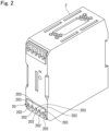
Fig. 2 is a perspective view illustrating a second terminal block of the terminal block set ofFig. 1 . -
Fig. 3 is a side view illustrating a state in which a first terminal block and the second terminal block of the terminal block set ofFig. 1 are connected. -
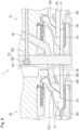
Fig. 4 is a sectional view illustrating a state in which the first terminal block and the second terminal block of the terminal block set ofFig. 1 are connected. -
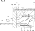
Fig. 5 is a sectional view illustrating the first terminal block of the terminal block set ofFig. 1 . -
Fig. 6 is a sectional view illustrating the second terminal block of the terminal block set ofFig. 1 . -
Fig. 7 is a circuit diagram illustrating an example of a determination unit of the terminal block set ofFig. 1 . -
Fig. 8 is a flowchart for explaining an example of display processing for displaying a second normal state using the terminal block set ofFig. 1 . -
Fig. 9 is a view illustrating an example of a jig of the terminal block set ofFig. 1 . - Hereinafter, an example of the present disclosure will be described with reference to the accompanying drawings. The following description is merely exemplary in nature and does not limit the present disclosure, applications of the present disclosure, and usage of the present disclosure. The accompanying drawings are schematic drawings, and the illustrated configuration and the product may have different dimensional ratios and the like.
- As shown in
Fig. 1 , a terminal block set 1 according to one aspect of the present disclosure includes afirst terminal block 10 and asecond terminal block 20. In the present aspect, thefirst terminal block 10 and thesecond terminal block 20 are terminal blocks of a push-in connection type. As illustrated inFig. 2 , thesecond terminal block 20 constitutes a part of apower supply device 2. - As illustrated in
Figs. 3 and4 , thefirst terminal block 10 and thesecond terminal block 20 are electrically connected via aconduction member 30. Theconduction member 30 includes, for example, a copper plate and an electric wire. In the present aspect, power is supplied from thefirst terminal block 10 to thesecond terminal block 20 via a cable 50 (an example of the conduction member) connected to thefirst terminal block 10. - The
first terminal block 10 is configured to be electrically connectable to different terminal blocks including thesecond terminal block 20. Thefirst terminal block 10 includes adetermination unit 11 and adisplay unit 12. In the present aspect, thefirst terminal block 10 and thesecond terminal block 20 include connectingportions portions cable 50 is connected to the connectingportion 13 of thefirst terminal block 10. - The
determination unit 11 is configured to determine whether or not a first voltage output to the connectedsecond terminal block 20 or a second voltage input from the connectedsecond terminal block 20 is normal. In the present aspect, thedetermination unit 11 is constituted by a circuit illustrated inFig. 7 as an example. In the circuit shown inFig. 7 , an AC voltage is input from anexternal power supply 60 to thefirst terminal block 10. The input AC voltage is divided and input to a comparator IC110. When the input AC voltage is equal to or higher than a threshold value, it is determined that the first voltage is normal, current flows through thedisplay unit 12 via a terminal K, and aLED 121 is turned on. It is also possible to determine whether or not the second voltage is normal with the same circuit configuration as the circuit illustrated inFig. 7 . In this case, a DC voltage output from thepower supply device 2 is input to thefirst terminal block 10. The input DC voltage is divided and input to the comparator IC110. When the input DC voltage is equal to or higher than the threshold value, it is determined that the second voltage is normal, current flows through thedisplay unit 12 via the terminal K, and theLED 121 is turned on. - When it is determined that the first voltage or the second voltage is normal, the
determination unit 11 causes thedisplay unit 12 to display "the first voltage is normal" or "the second voltage is normal." - The
determination unit 11 may include aprocessor 111 and astorage device 112. Theprocessor 111 and thestorage device 112 may constitute, for example, a part of the circuit illustrated inFig. 7 . Theprocessor 111 includes, for example, a CPU, an MPU, a GPU, a DSP, an FPGA, an ASIC, or a combination thereof. Thestorage device 112 includes, for example, a non-transitory computer-readable storage medium constituted by an internal recording medium or an external recording medium. The internal recording medium includes a nonvolatile memory or the like. The external recording medium includes a hard disk (HDD), a solid state drive (SSD), an optical disk device, or the like. Thedetermination unit 11 may be configured to transmit and receive data to and from an external device such as a server via a communication circuit or a communication module. - The
display unit 12 is configured to display "the first voltage is normal" or "the second voltage is normal" when it is determined that the first voltage or the second voltage is normal. - In the present aspect, the
display unit 12 includes alight emitting element 121. For example, as illustrated inFig. 4 , thelight emitting element 121 includes a light emitting diode (LED) 122 and a light guidingmember 123. In a state where thefirst terminal block 10 and thesecond terminal block 20 are connected, theLED 122 is located on asubstrate 124 on thefirst terminal block 10, thesubstrate 124 facing thesecond terminal block 20. By lightning of theLED 122, "the first voltage or the second voltage is normal" is displayed. - The first
terminal block 10 includes ahousing 101, and the connectingportion 13 is located inside thehousing 101. The secondterminal block 20 includes ahousing 201, and the connectingportion 21 is located inside thehousing 201. Each of the connectingportions terminal portion conduction member 30. - In a state illustrated in
Fig. 4 in which the firstterminal block 10 and the secondterminal block 20 are connected by theconduction member 30, thehousing 101 of the firstterminal block 10 includesopenings terminal block 20. Theopenings housing 201 of the secondterminal block 20 includesopenings terminal block 10. Theopenings openings terminal block 10 are connected to the connectingportion 13, and theopenings terminal block 20 are connected to the connectingportion 21. In the present aspect, thehousing 101 includes a plurality ofopenings 102 and a plurality ofopenings 103, and thehousing 201 includes a plurality ofopenings 202 and a plurality ofopenings 203. Thehousing 101 is provided with the same number of theopenings housing 201 is provided with the same number of theopenings - As illustrated in
Figs. 4 and5 , the connectingportion 13 of the firstterminal block 10 includes a leaf spring as an example. The leaf spring is configured to sandwich and hold thecable 50 accommodated through theopening 102 between the leaf spring and theterminal portion 131, and to release the holding of thecable 50 by a jig (not illustrated) accommodated in the connectingportion 13 through theopening 103. - As illustrated in
Figs. 4 and6 , the connectingportion 21 of the secondterminal block 20 is configured to accommodate a part of theconduction member 30, to hold the accommodated part of theconduction member 30, and to release the holding of theconduction member 30 by thejig 40. The part of theconduction member 30 is accommodated in the connectingportion 21 through theopening 202 of thehousing 201. Theopening 202 is an example of a first opening. - As an example, the connecting
portion 21 includes aleaf spring 212. Theleaf spring 212 is configured to sandwich and hold theconduction member 30 accommodated through theopening 202 between theleaf spring 212 and theterminal portion 211, and to release the holding of theconduction member 30 by thejig 40 accommodated in the connectingportion 21 through theopening 203. A part of thejig 40 is fixed to thehousing 101 of the firstterminal block 10, and thejig 40 extends outside thehousing 101 through theopening 103. A part of a portion of thejig 40 located outside thehousing 101 is accommodated in the connectingportion 21 through theopening 203 of thehousing 201. By bringing the firstterminal block 10 and the secondterminal block 20 close to each other, thejig 40 comes into contact with theleaf spring 212, and the holding of theconduction member 30 is released. Theopening 203 is an example of a second opening. - An example of display processing of displaying a second normal state using the terminal block set 1 will be described with reference to
Fig. 8 . This display processing is performed, for example, by theprocessor 111 executing a predetermined program stored in thestorage device 112. - As illustrated in
Fig. 8 , when the display processing is started, it is determined whether or not the secondterminal block 20 is connected (step S1). Step S1 is repeated until it is determined that the secondterminal block 20 is connected. Thedetermination unit 11 determines that the secondterminal block 20 is connected in the following cases, for example. - A case where a predetermined signal output from the second
terminal block 20 is received. - A case where an operation to start the display processing is performed on the first
terminal block 10 by a user. - When it is determined that the second
terminal block 20 is connected, thedetermination unit 11 acquires the first voltage or the second voltage (step S2). When the voltage is acquired, thedetermination unit 11 determines whether or not the acquired voltage is normal (step S3). Whether or not the acquired voltage is normal is determined based on, for example, whether or not the acquired voltage is equal to or higher than a predetermined threshold value. The predetermined threshold value of the voltage is set according to, for example, specifications of the secondterminal block 20. - When it is determined that the acquired voltage is normal, the
determination unit 11 causes thedisplay unit 12 to display that "the acquired voltage is normal" (step S4). - When the acquired voltage is not determined to be normal in step S3, or when "the acquired voltage is normal" is displayed by the
display unit 12 in step S4, thedetermination unit 11 determines whether or not to end the display processing (step S5). For example, thedetermination unit 11 determines to end the display processing in the following cases. - A case where a predetermined signal output from the second
terminal block 20 is not received for a predetermined period or longer. - A case where an operation to end the display processing is performed on the first
terminal block 10 by a user. - When it is determined to end the display processing, the display processing ends. When it is not determined to end the display processing, the process returns to step S2, and the first voltage or the second voltage is acquired. When the
display unit 12 displays "the acquired voltage is normal" in step S4, the process returns to step S2 while thedisplay unit 12 keeps displaying "the acquired voltage is normal". When the acquired voltage is not determined to be normal in step S3 while thedisplay unit 12 keeps displaying "the acquired voltage is normal", thedetermination unit 11 causes thedisplay unit 12 to end the display of "the acquired voltage is normal". - The first
terminal block 10 can exhibit the following advantageous effects. - The first terminal block electrically connectable to a different terminal block includes the
determination unit 11 and thedisplay unit 12. Thedetermination unit 11 is configured to determine whether or not the first voltage or the second voltage is normal. Thedisplay unit 12 is configured to display that the first voltage or the second voltage is normal when it is determined that the first voltage or the second voltage is normal. With such a configuration, it is possible to realize a terminal block capable of displaying that a voltage input to or output from a different terminal block is normal. - The
display unit 12 includes thelight emitting element 121. Thedetermination unit 11 is configured to cause thelight emitting element 121 to emit light when it is determined that the first voltage or the second voltage is normal. With such a configuration, it is possible to more reliably realize a terminal block capable of displaying that a voltage input to or output from a different terminal block is normal. - The terminal block set 1 can exhibit the following advantageous effects.
- The terminal block set 1 includes the first
terminal block 10, the secondterminal block 20, and theconduction member 30 configured to electrically connect the firstterminal block 10 and the secondterminal block 20. With such a configuration, it is possible to realize the terminal block set 1 that allows the firstterminal block 10 to display that the first voltage or the second voltage is normal. - The second
terminal block 20 includes thehousing 201. Thehousing 201 is configured to accommodate a part of theconduction member 30, to hold the accommodated part of theconduction member 30, and to release the holding of theconduction member 30 by thejig 40. Thehousing 201 includes thefirst opening 202 configured to insert theconduction member 30, and thesecond opening 203 provided adjacent to thefirst opening 202, thesecond opening 203 being configured to insert thejig 40. With such a configuration, it is possible to more reliably realize the terminal block set 1 that allows the firstterminal block 10 to display that the first voltage or the second voltage is normal. - The
jig 40 is fixed to the firstterminal block 10. With such a configuration, it is possible to more reliably realize the terminal block set 1 that allows the firstterminal block 10 to display that the first voltage or the second voltage is normal. - The terminal block set 1, the first
terminal block 10, and the secondterminal block 20 may be configured as follows. - The present disclosure may be applied not only to terminal blocks of the push-in connection type but also to terminal blocks having a different structure such as terminal blocks of a screw connection type.
- A length of the
conduction member 30 may be arbitrarily changed. Thejig 40 may be used in a state of being fixed to the firstterminal block 10 or in a state of being removed from the firstterminal block 10 according to the length of theconduction member 30. - The
display unit 12 is not limited to the case of including thelight emitting element 121, and may adopt any configuration by which it is possible to display that the first normal state or the second normal state. For example, thedisplay unit 12 may include a configuration configured to output sound in addition to thelight emitting element 121. - The connecting
portion 21 of the secondterminal block 20 may adopt any configuration configured to accommodate a part of theconduction member 30, to hold a part of the accommodatedconduction member 30, and to release the holding of theconduction member 30 by thejig 40. The configuration of thejig 40 may be changed according to the configuration of the connectingportion 21 of the secondterminal block 20. - For example, as shown in
Fig. 9 , thejig 40 may be configured to include a plurality ofprotrusions 41 configured to be simultaneously inserted into the plurality ofsecond openings 203 of the secondterminal block 20. Thejig 40 is configured to include at least the same number ofprotrusions 41 asconduction members 30 accommodated in the connectingportion 21 through thesecond opening 203 of the secondterminal block 20. When theconduction members 30 are inserted into all of the fivesecond openings 203 of the secondterminal block 20 inFig. 2 , thejig 40 is configured to include at least fiveprotrusions 41. By configuring in this manner, it is possible to more reliably realize the terminal block set 1 that allows the firstterminal block 10 to display that the first voltage or the second voltage is normal. - Various embodiments of the present disclosure have been described above in detail with reference to the drawings. Finally, various aspects of the present disclosure will be described. In the following description, reference numerals are added as an example.
- A terminal block according to a first aspect of the present disclosure is electrically connectable to a different terminal block, in which
the terminal block includes: - a
determination unit 11 configured to determine whether or not a first voltage or a second voltage is normal, the first voltage being output to the different terminal block connected to the terminal block, the second voltage being input from the different terminal block connected to the terminal block; and - a
display unit 12 configured to display that the first voltage or the second voltage is normal when the first voltage or the second voltage is determined to be normal. - The terminal block according to a second aspect of the present disclosure is the terminal block according to the first aspect, in which
- the
display unit 12 includes alight emitting element 121, and - the
determination unit 11 is configured to cause thelight emitting element 121 to emit light when the first voltage or the second voltage is determined to be normal. - A terminal block set 1 according to a third aspect of the present disclosure includes:
- a first
terminal block 10 that is the terminal block according to the first aspect or the second aspect; - a second
terminal block 20 that is the different terminal block; and - a
conduction member 30 configured to electrically connect the firstterminal block 10 and the secondterminal block 20. - The terminal block set 1 according to a fourth aspect of the present disclosure is the terminal block set 1 according to the third aspect, in which
the secondterminal block 20 includes: - a
housing 201 internally including a connectingportion 21, the connectingportion 21 being configured to accommodate a part of theconduction member 30, to hold a part of theconduction member 30 accommodated in theconnection portion 21, and to release the holding of theconduction member 30 by ajig 40, and - the
housing 201 includes:- a
first opening 202 configured to insert theconduction member 30; and - a
second opening 203 provided adjacent to thefirst opening 202, thesecond opening 203 being configured to insert thejig 40.
- a
- The terminal block set 1 according to a fifth aspect of the present disclosure is the terminal block set 1 according to the fourth aspect, in which
thejig 40 is fixed to the firstterminal block 10. - The terminal block set 1 according to a sixth aspect of the present disclosure is the terminal block set 1 according to the fourth or fifth aspect, in which
thehousing 201 includes: - a plurality of the
first openings 202; and - a plurality of the
second openings 203 respectively corresponding to each of the plurality of thefirst openings 202,
and - the
jig 40 includes:
a plurality ofprotrusions 41 configured to be simultaneously inserted into the plurality of thesecond openings 203. - The terminal block set 1 according to a seventh aspect of the present disclosure is the terminal block set 1 according to the sixth aspect, in which
thejig 40 includes at least the same number of theprotrusion 41 as theconduction member 30. - By appropriately combining arbitrary embodiments and modifications among the various embodiments and modifications described above, it is possible to achieve effects of the respective embodiments and modifications. In addition, combinations of embodiments, combinations of examples, and combinations of embodiments and examples are possible, and combinations of features in different embodiments and examples are also possible.
- Although the present disclosure has been described in each embodiment with a certain degree of detail, the disclosed content of these embodiments should be changed in the details of the configuration, and changing combinations and orders of elements in the embodiments can be realized without departing from the scope and the spirit of the present disclosure claimed herein.
- The present disclosure can be applied to, for example, a terminal block attached to a control panel or a power supply device.
-
- 1
- terminal block set
- 10
- first terminal block
- 11
- determination unit
- 111
- processor
- 112
- storage device
- 12
- display unit
- 121
- light emitting element
- 122
- LED
- 123
- light guiding member
- 124
- substrate
- 13
- connecting portion
- 131
- terminal portion
- 20
- second terminal block
- 21
- connecting portion
- 211
- terminal portion
- 30
- conduction member
- 40
- jig
- 101, 201
- housing
- 102, 103, 202, 203
- opening
Claims (7)
- A terminal block configured to electrically connect to a different terminal block, comprising:a determination unit (11) configured to determine whether or not a first voltage or a second voltage is normal, the first voltage being output to the different terminal block connected to the terminal block, the second voltage being input from the different terminal block connected to the terminal block; anda display unit (12) configured to display that the first voltage or the second voltage is normal when the first voltage or the second voltage is determined to be normal.
- The terminal block according to claim 1, whereinthe display unit (12) includes a light emitting element (121), andthe determination unit (11) is configured to cause the light emitting element (121) to emit light when the first voltage or the second voltage is determined to be normal.
- A terminal block set (1), comprising:a first terminal block (10) that is the terminal block according to claim 1 or 2;a second terminal block (20) that is the different terminal block; anda conduction member (30) configured to electrically connect the first terminal block (10) and the second terminal block (20).
- The terminal block set (1) according to claim 3, wherein
the second terminal block (20) includes:a housing (201) internally including a connecting portion (21), the connecting portion (21) being configured to accommodate a part of the conduction member (30), to hold a part of the conduction member (30) accommodated in the connection portion (21), and to release the holding of the conduction member (30) by a jig (40), andthe housing (201) includes:a first opening (202) configured to insert the conduction member (30); anda second opening (203) provided adjacent to the first opening (202), the second opening (203) being configured to insert the jig (40). - The terminal block set (1) according to claim 4, wherein
the jig (40) is fixed to the first terminal block (10). - The terminal block set (1) according to claim 4 or 5, wherein
the housing (201) includes:a plurality of the first openings (202); anda plurality of the second openings (203) respectively corresponding to each of the plurality of the first openings (202),
andthe jig (40) includes:
a plurality of protrusions (41) configured to be simultaneously inserted into the plurality of the second openings (203). - The terminal block set (1) according to claim 6, wherein
the jig (40) includes at least the same number of the protrusion (41) as the conduction member (30).
Applications Claiming Priority (1)
| Application Number | Priority Date | Filing Date | Title |
|---|---|---|---|
| JP2023216926A JP2025099927A (en) | 2023-12-22 | 2023-12-22 | Terminal block and terminal block set |
Publications (1)
| Publication Number | Publication Date |
|---|---|
| EP4576437A1 true EP4576437A1 (en) | 2025-06-25 |
Family
ID=93841316
Family Applications (1)
| Application Number | Title | Priority Date | Filing Date |
|---|---|---|---|
| EP24218072.7A Withdrawn EP4576437A1 (en) | 2023-12-22 | 2024-12-06 | Terminal block and terminal block set |
Country Status (3)
| Country | Link |
|---|---|
| EP (1) | EP4576437A1 (en) |
| JP (1) | JP2025099927A (en) |
| CN (1) | CN120200069A (en) |
Citations (2)
| Publication number | Priority date | Publication date | Assignee | Title |
|---|---|---|---|---|
| JP2006019173A (en) | 2004-07-02 | 2006-01-19 | Taniguchi Heaters Kk | Terminal block structure integrated with current display function |
| JP5032969B2 (en) * | 2007-12-18 | 2012-09-26 | パナソニック株式会社 | DC outlet |
-
2023
- 2023-12-22 JP JP2023216926A patent/JP2025099927A/en active Pending
-
2024
- 2024-11-28 CN CN202411725012.0A patent/CN120200069A/en active Pending
- 2024-12-06 EP EP24218072.7A patent/EP4576437A1/en not_active Withdrawn
Patent Citations (2)
| Publication number | Priority date | Publication date | Assignee | Title |
|---|---|---|---|---|
| JP2006019173A (en) | 2004-07-02 | 2006-01-19 | Taniguchi Heaters Kk | Terminal block structure integrated with current display function |
| JP5032969B2 (en) * | 2007-12-18 | 2012-09-26 | パナソニック株式会社 | DC outlet |
Also Published As
| Publication number | Publication date |
|---|---|
| JP2025099927A (en) | 2025-07-03 |
| CN120200069A (en) | 2025-06-24 |
Similar Documents
| Publication | Publication Date | Title |
|---|---|---|
| US6874907B2 (en) | USB-chargeable emergency light structure | |
| CN102170723B (en) | solid-state lighting system | |
| US9028122B2 (en) | Lighted electrical connector assembly | |
| US10314194B1 (en) | Expansion module of programmable logic controller | |
| US20130252469A1 (en) | Connection structure and connection unit of eletronic component | |
| WO2006126645A1 (en) | Socket for electronic part | |
| US9423111B2 (en) | Illumination device | |
| CN102650415B (en) | There is the solid-state lighting device of strain relief | |
| US7198520B1 (en) | In-line remote controllable power switch | |
| US11145439B2 (en) | Display device, and insertion and plugging protection device | |
| US20070167073A1 (en) | Electricity output device with a power supply | |
| US20120156923A1 (en) | Connection line | |
| JP2025099927A (en) | Terminal block and terminal block set | |
| US11677193B2 (en) | Power strip assembly with switch controlled outlet banks | |
| CN212011523U (en) | Concentrator | |
| JP7242139B2 (en) | Measuring units and modules | |
| US8564939B2 (en) | Method and apparatus for bypassing the battery of a computer | |
| JP3166538U (en) | LED module assembly structure | |
| US9655192B2 (en) | Power supply method, power supply system, and carrier module thereof | |
| CN113258324B (en) | Light source connection module and connector thereof | |
| US20070268634A1 (en) | Power supply system | |
| JP5975890B2 (en) | LED module, LED lighting device, and in-vehicle lamp | |
| CN106062910A (en) | Switch device and load control system | |
| CN113572030A (en) | power distribution panel | |
| US10067540B2 (en) | Front module and desktop computer system |
Legal Events
| Date | Code | Title | Description |
|---|---|---|---|
| PUAI | Public reference made under article 153(3) epc to a published international application that has entered the european phase |
Free format text: ORIGINAL CODE: 0009012 |
|
| STAA | Information on the status of an ep patent application or granted ep patent |
Free format text: STATUS: THE APPLICATION HAS BEEN PUBLISHED |
|
| AK | Designated contracting states |
Kind code of ref document: A1 Designated state(s): AL AT BE BG CH CY CZ DE DK EE ES FI FR GB GR HR HU IE IS IT LI LT LU LV MC ME MK MT NL NO PL PT RO RS SE SI SK SM TR |
|
| STAA | Information on the status of an ep patent application or granted ep patent |
Free format text: STATUS: THE APPLICATION IS DEEMED TO BE WITHDRAWN |
|
| 18D | Application deemed to be withdrawn |
Effective date: 20260103 |