EP4576435A1 - Insulation displacement connector - Google Patents
Insulation displacement connector Download PDFInfo
- Publication number
- EP4576435A1 EP4576435A1 EP24213620.8A EP24213620A EP4576435A1 EP 4576435 A1 EP4576435 A1 EP 4576435A1 EP 24213620 A EP24213620 A EP 24213620A EP 4576435 A1 EP4576435 A1 EP 4576435A1
- Authority
- EP
- European Patent Office
- Prior art keywords
- insulation displacement
- contact
- wire
- pair
- pieces
- Prior art date
- Legal status (The legal status is an assumption and is not a legal conclusion. Google has not performed a legal analysis and makes no representation as to the accuracy of the status listed.)
- Granted
Links
Images






Classifications
-
- H—ELECTRICITY
- H01—ELECTRIC ELEMENTS
- H01R—ELECTRICALLY-CONDUCTIVE CONNECTIONS; STRUCTURAL ASSOCIATIONS OF A PLURALITY OF MUTUALLY-INSULATED ELECTRICAL CONNECTING ELEMENTS; COUPLING DEVICES; CURRENT COLLECTORS
- H01R4/00—Electrically-conductive connections between two or more conductive members in direct contact, i.e. touching one another; Means for effecting or maintaining such contact; Electrically-conductive connections having two or more spaced connecting locations for conductors and using contact members penetrating insulation
- H01R4/24—Connections using contact members penetrating or cutting insulation or cable strands
- H01R4/2416—Connections using contact members penetrating or cutting insulation or cable strands the contact members having insulation-cutting edges, e.g. of tuning fork type
- H01R4/242—Connections using contact members penetrating or cutting insulation or cable strands the contact members having insulation-cutting edges, e.g. of tuning fork type the contact members being plates having a single slot
- H01R4/2425—Flat plates, e.g. multi-layered flat plates
- H01R4/2429—Flat plates, e.g. multi-layered flat plates mounted in an insulating base
- H01R4/2433—Flat plates, e.g. multi-layered flat plates mounted in an insulating base one part of the base being movable to push the cable into the slot
-
- H—ELECTRICITY
- H01—ELECTRIC ELEMENTS
- H01R—ELECTRICALLY-CONDUCTIVE CONNECTIONS; STRUCTURAL ASSOCIATIONS OF A PLURALITY OF MUTUALLY-INSULATED ELECTRICAL CONNECTING ELEMENTS; COUPLING DEVICES; CURRENT COLLECTORS
- H01R4/00—Electrically-conductive connections between two or more conductive members in direct contact, i.e. touching one another; Means for effecting or maintaining such contact; Electrically-conductive connections having two or more spaced connecting locations for conductors and using contact members penetrating insulation
- H01R4/24—Connections using contact members penetrating or cutting insulation or cable strands
- H01R4/2416—Connections using contact members penetrating or cutting insulation or cable strands the contact members having insulation-cutting edges, e.g. of tuning fork type
- H01R4/242—Connections using contact members penetrating or cutting insulation or cable strands the contact members having insulation-cutting edges, e.g. of tuning fork type the contact members being plates having a single slot
- H01R4/2425—Flat plates, e.g. multi-layered flat plates
-
- H—ELECTRICITY
- H01—ELECTRIC ELEMENTS
- H01R—ELECTRICALLY-CONDUCTIVE CONNECTIONS; STRUCTURAL ASSOCIATIONS OF A PLURALITY OF MUTUALLY-INSULATED ELECTRICAL CONNECTING ELEMENTS; COUPLING DEVICES; CURRENT COLLECTORS
- H01R4/00—Electrically-conductive connections between two or more conductive members in direct contact, i.e. touching one another; Means for effecting or maintaining such contact; Electrically-conductive connections having two or more spaced connecting locations for conductors and using contact members penetrating insulation
- H01R4/24—Connections using contact members penetrating or cutting insulation or cable strands
- H01R4/2404—Connections using contact members penetrating or cutting insulation or cable strands the contact members having teeth, prongs, pins or needles penetrating the insulation
-
- H—ELECTRICITY
- H01—ELECTRIC ELEMENTS
- H01R—ELECTRICALLY-CONDUCTIVE CONNECTIONS; STRUCTURAL ASSOCIATIONS OF A PLURALITY OF MUTUALLY-INSULATED ELECTRICAL CONNECTING ELEMENTS; COUPLING DEVICES; CURRENT COLLECTORS
- H01R13/00—Details of coupling devices of the kinds covered by groups H01R12/70 or H01R24/00 - H01R33/00
- H01R13/58—Means for relieving strain on wire connection, e.g. cord grip, for avoiding loosening of connections between wires and terminals within a coupling device terminating a cable
-
- H—ELECTRICITY
- H01—ELECTRIC ELEMENTS
- H01R—ELECTRICALLY-CONDUCTIVE CONNECTIONS; STRUCTURAL ASSOCIATIONS OF A PLURALITY OF MUTUALLY-INSULATED ELECTRICAL CONNECTING ELEMENTS; COUPLING DEVICES; CURRENT COLLECTORS
- H01R13/00—Details of coupling devices of the kinds covered by groups H01R12/70 or H01R24/00 - H01R33/00
- H01R13/62—Means for facilitating engagement or disengagement of coupling parts or for holding them in engagement
-
- H—ELECTRICITY
- H01—ELECTRIC ELEMENTS
- H01R—ELECTRICALLY-CONDUCTIVE CONNECTIONS; STRUCTURAL ASSOCIATIONS OF A PLURALITY OF MUTUALLY-INSULATED ELECTRICAL CONNECTING ELEMENTS; COUPLING DEVICES; CURRENT COLLECTORS
- H01R4/00—Electrically-conductive connections between two or more conductive members in direct contact, i.e. touching one another; Means for effecting or maintaining such contact; Electrically-conductive connections having two or more spaced connecting locations for conductors and using contact members penetrating insulation
- H01R4/24—Connections using contact members penetrating or cutting insulation or cable strands
- H01R4/2416—Connections using contact members penetrating or cutting insulation or cable strands the contact members having insulation-cutting edges, e.g. of tuning fork type
- H01R4/2445—Connections using contact members penetrating or cutting insulation or cable strands the contact members having insulation-cutting edges, e.g. of tuning fork type the contact members having additional means acting on the insulation or the wire, e.g. additional insulation penetrating means, strain relief means or wire cutting knives
-
- H—ELECTRICITY
- H01—ELECTRIC ELEMENTS
- H01R—ELECTRICALLY-CONDUCTIVE CONNECTIONS; STRUCTURAL ASSOCIATIONS OF A PLURALITY OF MUTUALLY-INSULATED ELECTRICAL CONNECTING ELEMENTS; COUPLING DEVICES; CURRENT COLLECTORS
- H01R4/00—Electrically-conductive connections between two or more conductive members in direct contact, i.e. touching one another; Means for effecting or maintaining such contact; Electrically-conductive connections having two or more spaced connecting locations for conductors and using contact members penetrating insulation
- H01R4/24—Connections using contact members penetrating or cutting insulation or cable strands
- H01R4/2416—Connections using contact members penetrating or cutting insulation or cable strands the contact members having insulation-cutting edges, e.g. of tuning fork type
- H01R4/2445—Connections using contact members penetrating or cutting insulation or cable strands the contact members having insulation-cutting edges, e.g. of tuning fork type the contact members having additional means acting on the insulation or the wire, e.g. additional insulation penetrating means, strain relief means or wire cutting knives
- H01R4/245—Connections using contact members penetrating or cutting insulation or cable strands the contact members having insulation-cutting edges, e.g. of tuning fork type the contact members having additional means acting on the insulation or the wire, e.g. additional insulation penetrating means, strain relief means or wire cutting knives the additional means having two or more slotted flat portions
Definitions
- the present disclosure relates to an insulation displacement connector.
- Patent Literature 1 Japanese Unexamined Patent Application Publication No. 2011-29125 discloses an insulation displacement connector 104 that includes an insulation displacement contact (IDC) 102 where a wire 101 is press-fit between a pair of IDC blades 100 and a compressing member 103 in a cylindrical shape that pushes the pair of IDC blades 100 so that the pair of IDC blades 100 come closer to each other.
- IDC insulation displacement contact
- the wire 101 is press-fit into a slot 106 between the pair of IDC blades 100.
- a covering 107 of the wire 101 is thereby cut by the pair of the pair of IDC blades 100.
- This cutting causes a core wire 108 of the wire 101 to be exposed, and the exposed core wire 108 comes into contact with the pair of IDC blades 100.
- the pair of IDC blades 100 are pushed by the compressing member 103 so as to come closer to each other and thereby the slot 106 is narrowed, and consequently an oxide layer formed on the core wire 108 of the wire 101 is removed.
- Patent Literature 1 room for improvement remains in terms of contact reliability.
- An object of the present disclosure is to provide an insulation displacement connector with high contact reliability.
- an insulation displacement connector including an insulation displacement contact including a base and a pair of insulation displacement pieces extending from the base, where a wire is press-fit into a slot formed between the pair of insulation displacement pieces and thereby a core wire of the wire comes into contact with the pair of insulation displacement pieces, and a twisting member configured to mate with the insulation displacement contact and thereby twist the wire so that a longitudinal direction of the core wire of the wire changes when viewed along a press-fit direction of press-fitting the wire into the slot of the insulation displacement contact.
- an insulation displacement connector with high contact reliability is achieved.
- the twisting member 5 is formed in S shape when viewed from above.
- the twisting member 5 includes a pair of covering contact pieces 20, a pair of pushing parts 21, a coupling part 22, and a pair of member-side lock parts 23.
- the first member-side lock part 38 is opposed to the first contact-side lock part 18 in the vertical direction, and it is located down below the first contact-side lock part 18.
- the second member-side lock part 39 is opposed to the second contact-side lock part 19 in the vertical direction, and it is located down below the second contact-side lock part 19. This restricts the twisting member 5 from moving upward relative to the insulation displacement contact 3 in the state where the twisting member 5 mates with the insulation displacement contact 3, so that mating of the twisting member 5 and the insulation displacement contact 3 is locked.
- the first member-side lock part 38 comes into contact with the first contact-side lock part 18 and thereby the first member-side lock part 38 is elastically displaced outward in the width direction as the first covering contact piece 30 is twisted and deformed, and after the first member-side lock part 38 climbs over the first contact-side lock part 18, the first member-side lock part 38 is elastically restored inward in the width direction by the elastic restoring force of the first covering contact piece 30. Consequently, the first contact-side lock part 18 and the first member-side lock part 38 are aligned in this recited order from top to bottom, and the first contact-side lock part 18 and the first member-side lock part 38 are opposed to each other in the vertical direction.
- Mating the twisting member 5 with the insulation displacement contact 3 means establishing the above-described positional relation of the first contact-side lock part 18, the second contact-side lock part 19, the first member-side lock part 38, and the second member-side lock part 39. This positional relation restricts the twisting member 5 from moving upward relative to the insulation displacement contact 3, so that mating of the insulation displacement contact 3 and the twisting member 5 is locked.
- the pair of IDC pieces 11 come into contact with the pair of pushing parts 21, respectively, in the width direction, and thereby an inward force in the width direction acts on the pair of IDC pieces 11.
- This increases the contact pressure of the core wire 7 of the wire 2 on the pair of IDC pieces 11, which improves the contact reliability between the core wire 7 of the wire 2 and the insulation displacement contact 3.
- the pair of pushing parts 21 are slightly elastically displaced outward in the width direction with elastic displacement of the pair of covering contact pieces 20 and the coupling part 22, thereby absorbing a certain degree of dimensional error during manufacture. This prevents an excessive inward force in the width direction from acting on the pair of IDC pieces 11 when the pair of IDC pieces 11 come into contact with the pair of pushing parts 21, respectively, in the width direction, which protects the core wire 7 from damage.
- the first covering contact piece 30 and the second covering contact piece 31 are pushed inward in the width direction against the covering 8 of the wire 2.
- the first covering contact piece 30 and the second covering contact piece 31 are disposed on opposite sides to each other with the insulation displacement contact 3 interposed therebetween and also disposed on opposite sides to each other with the wire 2 interposed therebetween when viewed from above in Fig. 9 .
- a couple acts on the wire 2. Consequently, the wire 2 is twisted locally counter-clockwise in a proximity area P of the wire press-fit slot 12 of the insulation displacement contact 3.
- the longitudinal direction of the wire 2 in the proximity area P is shown by a line segment Q.
- the line segment Q is inclined counter-clockwise relative to the wire direction when viewed from above. This inclination locally significantly increases the contact pressure of the core wire 7 of the wire 2 on the first IDC piece 16. Likewise, this inclination locally significantly increases the contact pressure of the core wire 7 of the wire 2 on the second IDC piece 17. As a result, the maximum value of the contact pressure of the core wire 7 of the wire 2 on the insulation displacement contact 3 is higher than that before mating, which achieves high contact reliability between the wire 2 and the insulation displacement contact 3.
- the problem that the contact pressure of the core wire 7 of the wire 2 on the pair of IDC pieces 11 decreases due to displacement of the pair of IDC pieces 11 outward in the width direction by stress relaxation is reduced by another approach.
- the second pushing part 34 is inclined relative to the wire direction when viewed from above.
- the second pushing part 34 projects in the first wire direction so as to come apart from the wire 2 when viewed from above.
- the second pushing part 34 slides over the second IDC piece 17 and is displaced in the second wire direction.
- the insulation displacement connector 1 includes the insulation displacement contact 3 and the twisting member 5.
- the insulation displacement contact 3 includes the base 10 and the pair of IDC pieces 11 extending from the base 10.
- the wire 2 is press-fit into the wire press-fit slot 12 (slot) formed between the pair of IDC pieces 11, and thereby the core wire 7 of the wire 2 comes into contact with the pair of IDC pieces 11.
- Fig. 1 the insulation displacement connector 1 includes the insulation displacement contact 3 and the twisting member 5.
- the insulation displacement contact 3 includes the base 10 and the pair of IDC pieces 11 extending from the base 10.
- the wire 2 is press-fit into the wire press-fit slot 12 (slot) formed between the pair of IDC pieces 11, and thereby the core wire 7 of the wire 2 comes into contact with the pair of IDC pieces 11.
- twisting member 5 further includes the coupling part 22 that couples the pair of covering contact pieces 20 and is inserted into the wire press-fit slot 12 of the insulation displacement contact 3. This structure prevents the wire 2 from being pulled upward out of the wire press-fit slot 12.
- the twisting member 5 includes the pair of pushing parts 21 that push the pair of IDC pieces 11, respectively, so that the pair of IDC pieces 11 come closer to each other. This structure further increases the contact pressure of the core wire 7 of the wire 2 on the pair of IDC pieces 11.
- the pair of pushing parts 21 are formed to project from the pair of covering contact pieces 20, respectively. This structure allows the pair of pushing parts 21 to come apart from each other with elastic deformation of the pair of covering contact pieces 20, which prevents an excessive increase in the contact pressure of the core wire 7 of the wire 2 on the pair of IDC pieces 11.
- the pair of pushing parts 21 project to be apart from the wire 2.
- the pair of IDC pieces 11 come apart from each other by stress relaxation
- the pair of pushing parts 21 slide over the pair of IDC pieces 11, respectively, and the pair of covering contact pieces 20 rotate about the coupling part 22 so as to be apart from the pair of IDC pieces 11 when viewed from above shown in Fig. 11 .
- This rotation increases a couple that is generated when the pair of covering contact pieces 20 come into contact with the covering 8 of the wire 2.
- the contact pressure of the core wire 7 of the wire 2 on the pair of IDC pieces 11 is maintained.
- the pair of pushing parts 21, the pair of covering contact pieces 20, and the coupling part 22 form an S-shape when viewed along the press-fit direction. This allows the twisting member 5 to be achieved in a simple structure.
- the first pushing part 33 which is one of the pair of pushing parts 21, the first covering contact piece 30, which is one of the pair of covering contact pieces 20, the coupling part 22, the second covering contact piece 31, which is the other one of the pair of covering contact pieces 20, and the second pushing part 34, which is the other one of the pair of pushing parts 21, are linked together in this recited order.
- the insulation displacement contact 3 includes the pair of contact-side lock parts 15.
- the twisting member 5 includes the pair of member-side lock parts 23. In the state where the twisting member 5 mates with the insulation displacement contact 3, the pair of contact-side lock parts 15 and the pair of member-side lock parts 23 are aligned in this recited order down below, which locks mating of the twisting member 5 and the insulation displacement contact 3. This structure allows the mating state of the twisting member 5 and the insulation displacement contact 3 to be maintained stably.
- the pair of covering contact pieces 20 may cut the covering 8 of the wire 2 and come into direct contact with the core wire 7 of the wire 2.
- one of the pair of contact-side lock parts 15 may be omitted.
- one of the pair of member-side lock parts 23 may be omitted. All of the pair of contact-side lock parts 15 and the pair of member-side lock parts 23 may be omitted.
- the twisting member 5 forms an S-shape when viewed from above in the above-described embodiment.
- the twisting member 5 may form an inverted S-shape when viewed from above.
- the wire 2 rotates clockwise when viewed from above.
- the insulation displacement connector 1 is a connector in which when the wire 2 is pushed into the insulation displacement contact 3 (IDC: Insulation Displacement Contact) without removing the covering 8 of the wire 2, the covering 8 of the wire 2 is locally cut and thereby the core wire 7 of the wire 2 becomes electrically continuous with the insulation displacement contact 3.
- the insulation displacement contact 3 is a terminal that is able to come into electrical contact with the core wire 7 of the wire 2 by locally cutting the covering 8 of the wire 2.
Landscapes
- Connections By Means Of Piercing Elements, Nuts, Or Screws (AREA)
- Coupling Device And Connection With Printed Circuit (AREA)
Abstract
Description
- The present disclosure relates to an insulation displacement connector.
- As shown in
Fig. 12 of the present application, Patent Literature 1 (Japanese Unexamined Patent Application Publication No. 2011-29125 insulation displacement connector 104 that includes an insulation displacement contact (IDC) 102 where awire 101 is press-fit between a pair ofIDC blades 100 and a compressingmember 103 in a cylindrical shape that pushes the pair ofIDC blades 100 so that the pair ofIDC blades 100 come closer to each other. To be specific, when the pair ofIDC blades 100 of the insulation displacement contact 102 mate with amating space 105 of the compressingmember 103, thewire 101 is press-fit into aslot 106 between the pair ofIDC blades 100. A covering 107 of thewire 101 is thereby cut by the pair of the pair ofIDC blades 100. This cutting causes acore wire 108 of thewire 101 to be exposed, and the exposedcore wire 108 comes into contact with the pair ofIDC blades 100. Further, by this mating, the pair ofIDC blades 100 are pushed by thecompressing member 103 so as to come closer to each other and thereby theslot 106 is narrowed, and consequently an oxide layer formed on thecore wire 108 of thewire 101 is removed. - In the above-described Patent Literature 1, room for improvement remains in terms of contact reliability.
- An object of the present disclosure is to provide an insulation displacement connector with high contact reliability.
- There is provided an insulation displacement connector including an insulation displacement contact including a base and a pair of insulation displacement pieces extending from the base, where a wire is press-fit into a slot formed between the pair of insulation displacement pieces and thereby a core wire of the wire comes into contact with the pair of insulation displacement pieces, and a twisting member configured to mate with the insulation displacement contact and thereby twist the wire so that a longitudinal direction of the core wire of the wire changes when viewed along a press-fit direction of press-fitting the wire into the slot of the insulation displacement contact.
- According to the present disclosure, an insulation displacement connector with high contact reliability is achieved.
- The above and other objects, features and advantages of the present disclosure will become more fully understood from the detailed description given hereinbelow and the accompanying drawings.
-
-
Fig. 1 is a perspective view of an insulation displacement connector before mating; -
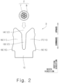
Fig. 2 is a front view of an insulation displacement contact before a wire is press-fit thereinto; -
Fig. 3 is a front view of the insulation displacement contact after a wire is press-fit thereinto; -
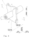
Fig. 4 is a perspective view showing the mating state of the insulation displacement connector; -
Fig. 5 is a perspective view of a twisting member; -
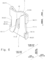
Fig. 6 is a perspective view showing the mating state of the insulation displacement connector; -
Fig. 7 is a plan view showing the mating state of the insulation displacement connector; -
Fig. 8 is a plan sectional view of the insulation displacement contact after a wire is press-fit thereinto; -
Fig. 9 is a plan sectional view showing the mating state of the insulation displacement connector; -
Fig. 10 is a partial plan view of the insulation displacement connector when the insulation displacement contact is deformed by stress relaxation; -
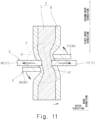
Fig. 11 is a plan sectional view of the insulation displacement connector when the insulation displacement contact is deformed by stress relaxation; and -
Fig. 12 is a view showing a simplified version ofFig. 4 of Patent Literature 1. - Although the present disclosure will be described hereinafter through an embodiment of the disclosure, the disclosure defined by the scope of claims is not limited to the following embodiment. Further, not all of the elements described in the embodiment are essential as a solution to problem. The following description and the drawings are appropriately shortened and simplified to clarify the explanation. In the drawings, the identical reference symbols denote identical structural elements and the redundant explanation thereof is omitted according to need.
-
Fig. 1 is a perspective view of an insulation displacement connector 1 and awire 2. As shown inFig. 1 , the insulation displacement connector 1 includes aninsulation displacement contact 3, an insulation displacement contact-side housing 4 that holds theinsulation displacement contact 3, atwisting member 5, and a twisting member-side housing 6 that holds thetwisting member 5. InFig. 1 , the insulation displacement contact-side housing 4 and the twisting member-side housing 6 are shown by chain double-dashed lines. Theinsulation displacement contact 3 and the twistingmember 5 are held by the insulation displacement contact-side housing 4 and the twisting member-side housing 6, respectively, typically by press fitting or insert molding. Theinsulation displacement contact 3 and the twistingmember 5 are formed typically by pressing a sheet metal such as copper and copper alloy. The insulation displacement contact-side housing 4 and the twisting member-side housing 6 are formed typically by injection molding an insulating resin such as PBT (Polybutylene terephthalate), PPS (Poly Phenylene Sulfide), nylon resin, and LCP (Liquid Crystal Polymer; registered trademark). The insulation displacement contact-side housing 4 and the twisting member-side housing 6 can be omitted. - The
wire 2 includes acore wire 7 and aninsulative covering 8 that covers thecore wire 7. Thecore wire 7 is typically a stranded wire made of copper, copper alloy, aluminum, aluminum alloy or the like. -
Figs. 2 and3 show press-fitting thewire 2 into theinsulation displacement contact 3. As shown inFigs. 1 to 3 , theinsulation displacement contact 3 is typically in flat plate shape. Theinsulation displacement contact 3 includes abase 10 that is held by the insulation displacement contact-side housing 4 and a pair of insulation displacement pieces (IDC pieces) 11 that extend from thebase 10. - The pair of
IDC pieces 11 extend in the same direction from thebase 10. The pair ofIDC pieces 11 are disposed apart from each other. Thus, a wire press-fit slot 12 is formed between the pair ofIDC pieces 11. As shown inFigs. 2 and3 , thewire 2 is press-fit into the wire press-fit slot 12 by using a jig, which is not shown, and thereby thecovering 8 of thewire 2 is cut by the pair ofIDC pieces 11, and the exposedcore wire 7 comes into electrical contact with the pair ofIDC pieces 11. As shown inFig. 3 , as thecore wire 7 is press-fit into the wire press-fit slot 12, it is crushed in the direction where the pair ofIDC pieces 11 are opposed to each other. Note that, although thecore wire 7 is still a stranded wire after crushed, it is shown as a single wire inFig. 3 for the sake of convenience. In the state where thewire 2 is press-fit into theinsulation displacement contact 3, thewire 2 extends in the thickness direction of theinsulation displacement contact 3. - Referring to
Figs. 1 to 3 , a wire direction, a width direction, and a vertical direction are defined as follows. The wire direction, the width direction, and the vertical direction are orthogonal to one another. The wire direction is a longitudinal direction of thewire 2 that is press-fit into theinsulation displacement contact 3. Since the longitudinal direction of thewire 2 coincides with the thickness direction of theinsulation displacement contact 3, the wire direction corresponds to the thickness direction of theinsulation displacement contact 3. The width direction is a direction where the pair ofIDC pieces 11 are opposed to each other. The width direction includes inward in the width direction and outward in the width direction. A direction that is inward in the width direction is a direction of viewing the wire press-fit slot 12 from the pair ofIDC pieces 11. A direction that is outward in the width direction is a direction of viewing the pair ofIDC pieces 11 from the wire press-fit slot 12. The vertical direction includes downward, which is a press-fit direction of press-fitting thewire 2 into theinsulation displacement contact 3, and upward, which is the opposite direction thereto. Note that the wire direction, the width direction, and the vertical direction are directions that are defined by way of illustration only, and those terms should not be interpreted as limiting the position of the insulation displacement connector 1 when actually used. - Referring further to
Fig. 2 , theinsulation displacement contact 3 is described hereinafter. As shown inFig. 2 , the wire press-fit slot 12 is formed to get wider toward the top. To be specific, the wire press-fit slot 12 includes awire accommodation part 13 and awire guide part 14. Thewire accommodation part 13 and thewire guide part 14 are located in this recited order from bottom to top. Thewire accommodation part 13 accommodates thewire 2 that is press-fit into theinsulation displacement contact 3. The wire guidepart 14 guides thewire 2 to thewire accommodation part 13. Thus, while thewire accommodation part 13 is formed to get slightly wider toward the top, thewire guide part 14 is formed to get significantly wider toward the top. - The
insulation displacement contact 3 further includes a pair of contact-side lock parts 15. The pair of contact-side lock parts 15 are respectively formed to project outward in the width direction from the root of the pair ofIDC pieces 11. - For convenience of description, the pair of
IDC pieces 11 are referred to hereinafter as afirst IDC piece 16 and asecond IDC piece 17 in some cases. Further, the pair of contact-side lock parts 15 are referred to hereinafter as a first contact-side lock part 18 and a second contact-side lock part 19 in some cases. As shown inFig. 2 , thefirst IDC piece 16 and the first contact-side lock part 18 are disposed on one side when viewed from the wire press-fit slot 12, and thesecond IDC piece 17 and the second contact-side lock part 19 are disposed on the other side when viewed from the wire press-fit slot 12. - Referring back to
Fig. 1 , the twistingmember 5 is used to improve the contact reliability between thecore wire 7 of thewire 2 and theinsulation displacement contact 3.Fig. 4 shows the state where the twistingmember 5 mates with theinsulation displacement contact 3 into which thewire 2 is press-fit. As shown inFigs. 1 and4 , the twistingmember 5 moves downward relatively toward theinsulation displacement contact 3 and thereby mates with theinsulation displacement contact 3. The twistingmember 5 mates with theinsulation displacement contact 3 in this manner, which improves the contact reliability between thecore wire 7 of thewire 2 and theinsulation displacement contact 3. In the state where the twistingmember 5 mates with theinsulation displacement contact 3, the position of the twistingmember 5 with respect to theinsulation displacement contact 3 is uniquely determined. Thus, in the following description of the twistingmember 5, the wire direction, the width direction, and the vertical direction defined earlier in the description of theinsulation displacement contact 3 are used in the same way. -
Fig. 5 is a perspective view of the twistingmember 5.Fig. 6 is a perspective view of the twistingmember 5 that mates with theinsulation displacement contact 3. Note that, inFig. 6 , thewire 2 is not illustrated for convenience of description.Fig. 7 is a plan view of the twistingmember 5 that mates with theinsulation displacement contact 3. Note that, inFig. 7 , thewire 2 is shown in a simplified manner with chain double-dashed lines for convenience of description. - As shown in
Figs. 5 to 7 , the twistingmember 5 is formed in S shape when viewed from above. To be specific, the twistingmember 5 includes a pair of coveringcontact pieces 20, a pair of pushingparts 21, acoupling part 22, and a pair of member-side lock parts 23. - As shown in
Fig. 5 , the pair of coveringcontact pieces 20 extend in the vertical direction. The pair of coveringcontact pieces 20 are apart from each other in the width direction. The thickness direction of the pair of coveringcontact pieces 20 coincides with the wire direction. The pair of coveringcontact pieces 20 are slightly out of alignment in the wire direction. A first wire direction and a second wire direction are defined as follows with reference toFigs. 5 and6 . The first wire direction and the second wire direction are directions parallel to the wire direction and opposite to each other. Thus, the first wire direction and the second wire direction can be referred to also as a first wire orientation and a second wire orientation, respectively. The pair of coveringcontact pieces 20 include a firstcovering contact piece 30 and a secondcovering contact piece 31. When observing the twistingmember 5 along the width direction, the firstcovering contact piece 30 and the secondcovering contact piece 31 are disposed in this recited order along the second wire direction. Thus, when observing the twistingmember 5 along the width direction, the second wire direction is a direction of viewing the secondcovering contact piece 31 from thecovering contact piece 30. The pair of coveringcontact pieces 20 are coupled with each other through thecoupling part 22. In more detail, thecoupling part 22 couples the upper ends of the pair of coveringcontact pieces 20. Thus, the twistingmember 5 has awire accommodation slot 32 that is defined by the pair of coveringcontact pieces 20 in the wire direction, defined by thecoupling part 22 in the vertical direction, and opens downward. Thewire accommodation slot 32 is formed to get slightly wider toward the bottom. As shown inFigs. 6 and7 , the firstcovering contact piece 30 and the secondcovering contact piece 31 are opposed to thefirst IDC piece 16 and thesecond IDC piece 17, respectively, in the wire direction. - The pair of pushing
parts 21 are formed to project in the wire direction from the upper ends of the pair of coveringcontact pieces 20. The pair of pushingparts 21 include a first pushingpart 33 and a second pushingpart 34. - As shown in
Figs. 6 and7 , the first pushingpart 33 projects in the second wire direction from the upper end of the firstcovering contact piece 30 at its outward end in the width direction. As shown inFig. 7 , the first pushingpart 33 projects to be slightly inclined outward in the width direction relative to the wire direction as it goes toward the second wire direction. Thus, the first pushingpart 33 can be referred to as projecting to be apart from thewire 2. - As shown in
Figs. 6 and7 , the second pushingpart 34 projects in the first wire direction from the upper end of the secondcovering contact piece 31 at its outward end in the width direction. As shown inFig. 7 , the second pushingpart 34 projects to be slightly inclined outward in the width direction relative to the wire direction as it goes toward the first wire direction. Thus, the second pushingpart 34 can be referred to as projecting to be apart from thewire 2. - Therefore, as shown in
Fig. 7 , the pair of coveringcontact pieces 20, the pair of pushingparts 21, and thecoupling part 22 form an S-shape when viewed from above as described earlier. The first pushingpart 33, the firstcovering contact piece 30, thecoupling part 22, the secondcovering contact piece 31, and the second pushingpart 34 are linked together in this recited order. - Referring still to
Fig. 7 , in the state where the twistingmember 5 mates with theinsulation displacement contact 3, the pair of pushingparts 21 are opposed to the pair ofIDC pieces 11 in the width direction. To be specific, the first pushingpart 33 and the second pushingpart 34 are disposed outward in the width direction relative to thefirst IDC piece 16 and thesecond IDC piece 17, respectively. In the state where the twistingmember 5 mates with theinsulation displacement contact 3, the first pushingpart 33 and the second pushingpart 34 are in contact with thefirst IDC piece 16 and thesecond IDC piece 17, respectively, in the width direction. In the state where the twistingmember 5 mates with theinsulation displacement contact 3, the first pushingpart 33 and the second pushingpart 34 push thefirst IDC piece 16 and thesecond IDC piece 17, respectively, in the width direction by the elastic restoring force of the twistingmember 5 so that thefirst IDC piece 16 and thesecond IDC piece 17 come closer to each other. In other words, the first pushingpart 33 and the second pushingpart 34 push thefirst IDC piece 16 and thesecond IDC piece 17, respectively, inward in the width direction by the elastic restoring force of the twistingmember 5. This pushing enhances the contact pressure of thecore wire 7 of thewire 2 on the pair ofIDC pieces 11. - Referring to
Figs. 5 and6 , the pair of member-side lock parts 23 are formed to project in the wire direction from the lower ends of the pair of coveringcontact pieces 20, respectively. The pair of member-side lock parts 23 include a first member-side lock part 38 and a second member-side lock part 39. The first member-side lock part 38 projects in the second wire direction from the lower end of the firstcovering contact piece 30 at its outward end in the width direction. The second member-side lock part 39 projects in the first wire direction from the lower end of the secondcovering contact piece 31 at its outward end in the width direction. - As shown in
Fig. 6 , in the state where the twistingmember 5 mates with theinsulation displacement contact 3, the first member-side lock part 38 is opposed to the first contact-side lock part 18 in the vertical direction, and it is located down below the first contact-side lock part 18. Likewise, the second member-side lock part 39 is opposed to the second contact-side lock part 19 in the vertical direction, and it is located down below the second contact-side lock part 19. This restricts the twistingmember 5 from moving upward relative to theinsulation displacement contact 3 in the state where the twistingmember 5 mates with theinsulation displacement contact 3, so that mating of the twistingmember 5 and theinsulation displacement contact 3 is locked. - Press-fitting the
wire 2 into theinsulation displacement contact 3 is described hereinafter in detail. As shown inFigs. 2 and3 , if thewire 2 is press-fit into the wire press-fit slot 12 of theinsulation displacement contact 3, thewire 2 is compressed in the width direction as shown inFigs. 3 and8 . As shown inFig. 8 , the covering 8 of thewire 2 is cut by contact with the pair ofIDC pieces 11, and thereby thecore wire 7 of thewire 2 is exposed in the width direction. As a result, the exposedcore wire 7 comes into electrical contact with the pair ofIDC pieces 11 with a certain contact pressure. - Mating the twisting
member 5 with theinsulation displacement contact 3 is described hereinafter in detail. As shown inFigs. 1 and4 , to mate the twistingmember 5 with theinsulation displacement contact 3, in the state where theinsulation displacement contact 3 and the twistingmember 5 are opposed to each other in the vertical direction, the twistingmember 5 is displaced downward relatively toward theinsulation displacement contact 3. In this step, as shown inFig. 9 , the mating positional relation of theinsulation displacement contact 3 and the twistingmember 5 is such that the pair of coveringcontact pieces 20 of the twistingmember 5 are disposed on opposite sides to each other with theinsulation displacement contact 3 interposed therebetween and also disposed on opposite sides to each other with thewire 2 interposed therebetween when viewed from above. - If, maintaining the above-described mating positional relation, the twisting
member 5 is further displaced downward relatively toward theinsulation displacement contact 3, first, as shown inFig. 6 , the first member-side lock part 38 and the second member-side lock part 39 climb over the first contact-side lock part 18 and the second contact-side lock part 19, respectively, so that the twistingmember 5 mates with theinsulation displacement contact 3. To be specific, the first member-side lock part 38 comes into contact with the first contact-side lock part 18 and thereby the first member-side lock part 38 is elastically displaced outward in the width direction as the firstcovering contact piece 30 is twisted and deformed, and after the first member-side lock part 38 climbs over the first contact-side lock part 18, the first member-side lock part 38 is elastically restored inward in the width direction by the elastic restoring force of the firstcovering contact piece 30. Consequently, the first contact-side lock part 18 and the first member-side lock part 38 are aligned in this recited order from top to bottom, and the first contact-side lock part 18 and the first member-side lock part 38 are opposed to each other in the vertical direction. The same applies to the second member-side lock part 39 and the second contact-side lock part 19. Mating the twistingmember 5 with theinsulation displacement contact 3 means establishing the above-described positional relation of the first contact-side lock part 18, the second contact-side lock part 19, the first member-side lock part 38, and the second member-side lock part 39. This positional relation restricts the twistingmember 5 from moving upward relative to theinsulation displacement contact 3, so that mating of theinsulation displacement contact 3 and the twistingmember 5 is locked. - Second, as shown in
Fig. 4 , thecoupling part 22 of the twistingmember 5 is opposed to thewire 2 in the vertical direction. This prevents thewire 2 that is press-fit into theinsulation displacement contact 3 from being pulled out upward. Note that, in the mating state shown inFig. 4 , thecoupling part 22 of the twistingmember 5 is typically not in contact with the covering 8 of thewire 2 in the vertical direction. However, in the above-described mating state, thecoupling part 22 of the twistingmember 5 may be in contact with the covering 8 of thewire 2 in the vertical direction. - Third, as shown in
Fig. 7 , the pair ofIDC pieces 11 come into contact with the pair of pushingparts 21, respectively, in the width direction, and thereby an inward force in the width direction acts on the pair ofIDC pieces 11. This increases the contact pressure of thecore wire 7 of thewire 2 on the pair ofIDC pieces 11, which improves the contact reliability between thecore wire 7 of thewire 2 and theinsulation displacement contact 3. Note that, at this moment, the pair of pushingparts 21 are slightly elastically displaced outward in the width direction with elastic displacement of the pair of coveringcontact pieces 20 and thecoupling part 22, thereby absorbing a certain degree of dimensional error during manufacture. This prevents an excessive inward force in the width direction from acting on the pair ofIDC pieces 11 when the pair ofIDC pieces 11 come into contact with the pair of pushingparts 21, respectively, in the width direction, which protects thecore wire 7 from damage. - Fourth, as shown in
Fig. 9 , the firstcovering contact piece 30 and the secondcovering contact piece 31 are pushed inward in the width direction against the covering 8 of thewire 2. As described earlier, the firstcovering contact piece 30 and the secondcovering contact piece 31 are disposed on opposite sides to each other with theinsulation displacement contact 3 interposed therebetween and also disposed on opposite sides to each other with thewire 2 interposed therebetween when viewed from above inFig. 9 . Thus, as the firstcovering contact piece 30 and the secondcovering contact piece 31 are pushed inward in the width direction against the covering 8 of thewire 2 as described above, a couple acts on thewire 2. Consequently, thewire 2 is twisted locally counter-clockwise in a proximity area P of the wire press-fit slot 12 of theinsulation displacement contact 3. The longitudinal direction of thewire 2 in the proximity area P is shown by a line segment Q. As shown inFig. 9 , the line segment Q is inclined counter-clockwise relative to the wire direction when viewed from above. This inclination locally significantly increases the contact pressure of thecore wire 7 of thewire 2 on thefirst IDC piece 16. Likewise, this inclination locally significantly increases the contact pressure of thecore wire 7 of thewire 2 on thesecond IDC piece 17. As a result, the maximum value of the contact pressure of thecore wire 7 of thewire 2 on theinsulation displacement contact 3 is higher than that before mating, which achieves high contact reliability between thewire 2 and theinsulation displacement contact 3. - Stress relaxation in the
insulation displacement contact 3 is described hereinafter. As shown inFigs. 8 and9 , in the state where thewire 2 is press-fit into theinsulation displacement contact 3, an outward stress in the width direction is acting on the pair ofIDC pieces 11. Thus, the pair ofIDC pieces 11 are to be gradually displaced outward in the width direction so that the stress on the pair ofIDC pieces 11 is relaxed. This phenomenon is called stress relaxation phenomenon, and significantly appears particularly when theinsulation displacement contact 3 is exposed to high temperature. In this manner, when the pair ofIDC pieces 11 are displaced outward in the width direction, the contact pressure of thecore wire 7 of thewire 2 on the pair ofIDC pieces 11 decreases, which can hinder the contact reliability between thewire 2 and theinsulation displacement contact 3. As shown inFig. 7 , displacement of the pair ofIDC pieces 11 outward in the width direction by stress relaxation is prevented to a certain degree by the rigidity of the twistingmember 5 as the pair ofIDC pieces 11 are in contact with the pair of pushingparts 21 in the width direction. - In addition, in the insulation displacement connector 1 according to this embodiment, the problem that the contact pressure of the
core wire 7 of thewire 2 on the pair ofIDC pieces 11 decreases due to displacement of the pair ofIDC pieces 11 outward in the width direction by stress relaxation is reduced by another approach. To be specific, as shown inFig. 10 , the second pushingpart 34 is inclined relative to the wire direction when viewed from above. In more detail, the second pushingpart 34 projects in the first wire direction so as to come apart from thewire 2 when viewed from above. Thus, when thesecond IDC piece 17 is displaced outward in the width direction by stress relaxation, the second pushingpart 34 slides over thesecond IDC piece 17 and is displaced in the second wire direction. As a result, as shown inFig. 11 , the secondcovering contact piece 31 rotates counter-clockwise when viewed from above, together with the second pushingpart 34. Likewise, the firstcovering contact piece 30 rotates counter-clockwise when viewed from above, together with the first pushingpart 33. This rotation causes thewire 2 to further rotate counter-clockwise in the proximity area P. By this local rotation of thewire 2, the contact pressure of thecore wire 7 of thewire 2 on the pair ofIDC pieces 11 increases. Consequently, even if the pair ofIDC pieces 11 are displaced outward in the width direction by stress relaxation, the maximum value of the contact pressure of thecore wire 7 of thewire 2 on theinsulation displacement contact 3 does not largely decreases compared with that before displacement, which allows maintaining high contact reliability between thewire 2 and theinsulation displacement contact 3. - An embodiment of the present disclosure is described above. The above-described embodiment has the following features.
- As shown in
Fig. 1 , the insulation displacement connector 1 includes theinsulation displacement contact 3 and the twistingmember 5. Theinsulation displacement contact 3 includes thebase 10 and the pair ofIDC pieces 11 extending from thebase 10. As shown inFigs. 2 and3 , thewire 2 is press-fit into the wire press-fit slot 12 (slot) formed between the pair ofIDC pieces 11, and thereby thecore wire 7 of thewire 2 comes into contact with the pair ofIDC pieces 11. As shown inFig. 9 , the twistingmember 5 mates with theinsulation displacement contact 3 and thereby twists thewire 2 so that the orientation of the line segment Q (the longitudinal direction of thecore wire 7 of thewire 2 in the proximity area P) changes when viewed from above (when viewed along the press-fit direction of press-fitting thewire 2 into the wire press-fit slot 12 of the insulation displacement contact 3). This structure increases the contact pressure of thecore wire 7 of thewire 2 on the pair ofIDC pieces 11 and thereby achieves the insulation displacement connector 1 with high contact reliability. - As shown in
Fig. 9 , the twistingmember 5 includes the pair of coveringcontact pieces 20 that come into contact with the covering 8 of thewire 2. The pair of coveringcontact pieces 20 are disposed on opposite sides to each other with theinsulation displacement contact 3 interposed therebetween and also disposed on opposite sides to each other with thewire 2 interposed therebetween when viewed from above. In this structure, as the pair of coveringcontact pieces 20 come into contact with the covering 8 of thewire 2, a couple that twists thewire 2 acts on thewire 2. This allows the twistingmember 5 to be achieved in a simple structure. - Further, the twisting
member 5 further includes thecoupling part 22 that couples the pair of coveringcontact pieces 20 and is inserted into the wire press-fit slot 12 of theinsulation displacement contact 3. This structure prevents thewire 2 from being pulled upward out of the wire press-fit slot 12. - Further, as shown in
Fig. 7 , the twistingmember 5 includes the pair of pushingparts 21 that push the pair ofIDC pieces 11, respectively, so that the pair ofIDC pieces 11 come closer to each other. This structure further increases the contact pressure of thecore wire 7 of thewire 2 on the pair ofIDC pieces 11. - Further, as shown in
Fig. 7 , the pair of pushingparts 21 are formed to project from the pair of coveringcontact pieces 20, respectively. This structure allows the pair of pushingparts 21 to come apart from each other with elastic deformation of the pair of coveringcontact pieces 20, which prevents an excessive increase in the contact pressure of thecore wire 7 of thewire 2 on the pair ofIDC pieces 11. - Further, as shown in
Fig. 10 , in the state where the twistingmember 5 mates with theinsulation displacement contact 3 when viewed from above, the pair of pushingparts 21 project to be apart from thewire 2. In this structure, when the pair ofIDC pieces 11 come apart from each other by stress relaxation, the pair of pushingparts 21 slide over the pair ofIDC pieces 11, respectively, and the pair of coveringcontact pieces 20 rotate about thecoupling part 22 so as to be apart from the pair ofIDC pieces 11 when viewed from above shown inFig. 11 . This rotation increases a couple that is generated when the pair of coveringcontact pieces 20 come into contact with the covering 8 of thewire 2. Thus, in this structure, even when the pair ofIDC pieces 11 come apart from each other by stress relaxation, the contact pressure of thecore wire 7 of thewire 2 on the pair ofIDC pieces 11 is maintained. - Further, as shown in
Fig. 7 , the pair of pushingparts 21, the pair of coveringcontact pieces 20, and thecoupling part 22 form an S-shape when viewed along the press-fit direction. This allows the twistingmember 5 to be achieved in a simple structure. - Further, as shown in
Fig. 7 , the first pushingpart 33, which is one of the pair of pushingparts 21, the firstcovering contact piece 30, which is one of the pair of coveringcontact pieces 20, thecoupling part 22, the secondcovering contact piece 31, which is the other one of the pair of coveringcontact pieces 20, and the second pushingpart 34, which is the other one of the pair of pushingparts 21, are linked together in this recited order. - Further, as shown in
Fig. 6 , theinsulation displacement contact 3 includes the pair of contact-side lock parts 15. The twistingmember 5 includes the pair of member-side lock parts 23. In the state where the twistingmember 5 mates with theinsulation displacement contact 3, the pair of contact-side lock parts 15 and the pair of member-side lock parts 23 are aligned in this recited order down below, which locks mating of the twistingmember 5 and theinsulation displacement contact 3. This structure allows the mating state of the twistingmember 5 and theinsulation displacement contact 3 to be maintained stably. - The above-described embodiment may be modified as follows, for example.
- For example, in
Fig. 9 , the pair of coveringcontact pieces 20 may cut the covering 8 of thewire 2 and come into direct contact with thecore wire 7 of thewire 2. - In
Fig. 6 , one of the pair of contact-side lock parts 15 may be omitted. Likewise, one of the pair of member-side lock parts 23 may be omitted. All of the pair of contact-side lock parts 15 and the pair of member-side lock parts 23 may be omitted. - As shown in
Fig. 7 , the twistingmember 5 forms an S-shape when viewed from above in the above-described embodiment. However, the twistingmember 5 may form an inverted S-shape when viewed from above. In this case, in the proximity area P shown inFigs. 9 and11 , thewire 2 rotates clockwise when viewed from above. - Note that the insulation displacement connector 1 (IDC Connector) is a connector in which when the
wire 2 is pushed into the insulation displacement contact 3 (IDC: Insulation Displacement Contact) without removing thecovering 8 of thewire 2, the covering 8 of thewire 2 is locally cut and thereby thecore wire 7 of thewire 2 becomes electrically continuous with theinsulation displacement contact 3. Theinsulation displacement contact 3 is a terminal that is able to come into electrical contact with thecore wire 7 of thewire 2 by locally cutting the covering 8 of thewire 2. - From the disclosure thus described, it will be obvious that the embodiments of the disclosure may be varied in many ways. Such variations are not to be regarded as a departure from the spirit and scope of the disclosure, and all such modifications as would be obvious to one skilled in the art are intended for inclusion within the scope of the following claims.
Claims (9)
- An insulation displacement connector comprising:an insulation displacement contact including a base and a pair of insulation displacement pieces extending from the base, a wire being press-fit into a slot formed between the pair of insulation displacement pieces, and whereby a core wire of the wire comes into contact with the pair of insulation displacement pieces; anda twisting member configured to mate with the insulation displacement contact and thereby twist the wire so that a longitudinal direction of the core wire of the wire changes when viewed along a press-fit direction of press-fitting the wire into the slot of the insulation displacement contact.
- The insulation displacement connector according to claim 1, whereinthe twisting member includes a pair of covering contact pieces configured to come into contact with a covering of the wire, andthe pair of covering contact pieces are disposed in such a manner that the insulation displacement contact is interposed therebetween and also disposed in such a manner that the wire is interposed therebetween when viewed along the press-fit direction.
- The insulation displacement connector according to claim 2, wherein the twisting member further includes a coupling part coupling the pair of covering contact pieces and configured to be inserted into the slot of the insulation displacement contact.
- The insulation displacement connector according to claim 3, wherein the twisting member includes a pair of pushing parts configured to push the pair of insulation displacement pieces, respectively, so that the pair of insulation displacement pieces come closer to each other.
- The insulation displacement connector according to claim 4, wherein the pair of pushing parts are formed to project from the pair of covering contact pieces, respectively.
- The insulation displacement connector according to claim 5, wherein in the state where the twisting member mates with the insulation displacement contact, the pair of pushing parts project to be apart from the wire when viewed along the press-fit direction.
- The insulation displacement connector according to claim 5 or 6, wherein the pair of pushing parts, the pair of covering contact pieces, and the coupling part form an S-shape or an inverted S-shape when viewed along the press-fit direction.
- The insulation displacement connector according to claim 7, wherein one of the pair of pushing parts, one of the pair of covering contact pieces, the coupling part, another one of the pair of covering contact pieces, and another one of the pair of pushing parts are linked together in this recited order.
- The insulation displacement connector according to claim 1, whereinthe insulation displacement contact includes a contact-side lock part,the twisting member includes a member-side lock part, andin the state where the twisting member mates with the insulation displacement contact, the contact-side lock part and the member-side lock part are aligned in this recited order in the press-fit direction, so that mating of the twisting member and the insulation displacement contact is locked.
Applications Claiming Priority (1)
| Application Number | Priority Date | Filing Date | Title |
|---|---|---|---|
| JP2023212920A JP2025096923A (en) | 2023-12-18 | 2023-12-18 | Pressure Connector |
Publications (2)
| Publication Number | Publication Date |
|---|---|
| EP4576435A1 true EP4576435A1 (en) | 2025-06-25 |
| EP4576435B1 EP4576435B1 (en) | 2025-12-31 |
Family
ID=93562430
Family Applications (1)
| Application Number | Title | Priority Date | Filing Date |
|---|---|---|---|
| EP24213620.8A Active EP4576435B1 (en) | 2023-12-18 | 2024-11-18 | INSULATION SHIFT CONNECTOR |
Country Status (4)
| Country | Link |
|---|---|
| US (1) | US20250202135A1 (en) |
| EP (1) | EP4576435B1 (en) |
| JP (1) | JP2025096923A (en) |
| CN (1) | CN120184619A (en) |
Citations (4)
| Publication number | Priority date | Publication date | Assignee | Title |
|---|---|---|---|---|
| US3824527A (en) * | 1972-08-03 | 1974-07-16 | Amp Inc | Wire-in-slot electrical connections |
| US4089580A (en) * | 1977-02-25 | 1978-05-16 | Amp Incorporated | Multi-contact connector and contact terminal for flat cable having a plurality of conductors on close center lines |
| EP0014081A1 (en) * | 1979-01-24 | 1980-08-06 | The Post Office | Electrical termination |
| JP2011029125A (en) | 2009-07-29 | 2011-02-10 | Sumitomo Wiring Syst Ltd | Insulation displacement connector |
-
2023
- 2023-12-18 JP JP2023212920A patent/JP2025096923A/en active Pending
-
2024
- 2024-10-08 CN CN202411392904.3A patent/CN120184619A/en active Pending
- 2024-10-24 US US18/925,736 patent/US20250202135A1/en active Pending
- 2024-11-18 EP EP24213620.8A patent/EP4576435B1/en active Active
Patent Citations (4)
| Publication number | Priority date | Publication date | Assignee | Title |
|---|---|---|---|---|
| US3824527A (en) * | 1972-08-03 | 1974-07-16 | Amp Inc | Wire-in-slot electrical connections |
| US4089580A (en) * | 1977-02-25 | 1978-05-16 | Amp Incorporated | Multi-contact connector and contact terminal for flat cable having a plurality of conductors on close center lines |
| EP0014081A1 (en) * | 1979-01-24 | 1980-08-06 | The Post Office | Electrical termination |
| JP2011029125A (en) | 2009-07-29 | 2011-02-10 | Sumitomo Wiring Syst Ltd | Insulation displacement connector |
Also Published As
| Publication number | Publication date |
|---|---|
| JP2025096923A (en) | 2025-06-30 |
| EP4576435B1 (en) | 2025-12-31 |
| CN120184619A (en) | 2025-06-20 |
| US20250202135A1 (en) | 2025-06-19 |
Similar Documents
| Publication | Publication Date | Title |
|---|---|---|
| US5498173A (en) | Electrical connecting device | |
| US3954320A (en) | Electrical connecting devices for terminating cords | |
| US8251758B2 (en) | Electrical contact | |
| CN101183752B (en) | Socket connector with latch biasing member | |
| US9472875B2 (en) | Wire-to-board connector | |
| US11075479B2 (en) | Terminal fitting | |
| US20170271784A1 (en) | Electrical Connection Device, A Method of Manufacturing an Electrical Cable and A Manufactured Electrical Coaxial Cable | |
| KR0139698B1 (en) | Terminals for mating electrical connectors and blade contacts | |
| CN1192297A (en) | Electrical terminal | |
| JP2011134582A (en) | Connector for flat cable, method of manufacturing the same and lock mechanism | |
| US12334660B2 (en) | Electrical terminal for flat flexible cables | |
| US7255611B2 (en) | Connector | |
| EP3691047A1 (en) | Connector structure | |
| JP4632454B2 (en) | Cable connector | |
| EP4576435B1 (en) | INSULATION SHIFT CONNECTOR | |
| EP3667822B1 (en) | Crimp barrel terminal connection system for electrical connector | |
| CN113889774A (en) | Electrical terminal for flat flexible cable | |
| US12362503B2 (en) | Terminal which makes direct wire-to-wire or wire-to-mating surface connection | |
| CN113889776B (en) | Electrical terminal for flat flexible cable | |
| JP2000294335A (en) | Connector locking structure | |
| US12562507B1 (en) | Direct wire terminal assembly | |
| CN1218337C (en) | Microswitch | |
| US20250038431A1 (en) | Terminal having an insulation displacement contact | |
| CN217983905U (en) | Trailing edge unlocking connector | |
| JP7330051B2 (en) | Connectors and wire harnesses |
Legal Events
| Date | Code | Title | Description |
|---|---|---|---|
| PUAI | Public reference made under article 153(3) epc to a published international application that has entered the european phase |
Free format text: ORIGINAL CODE: 0009012 |
|
| STAA | Information on the status of an ep patent application or granted ep patent |
Free format text: STATUS: REQUEST FOR EXAMINATION WAS MADE |
|
| STAA | Information on the status of an ep patent application or granted ep patent |
Free format text: STATUS: EXAMINATION IS IN PROGRESS |
|
| 17P | Request for examination filed |
Effective date: 20241118 |
|
| AK | Designated contracting states |
Kind code of ref document: A1 Designated state(s): AL AT BE BG CH CY CZ DE DK EE ES FI FR GB GR HR HU IE IS IT LI LT LU LV MC ME MK MT NL NO PL PT RO RS SE SI SK SM TR |
|
| 17Q | First examination report despatched |
Effective date: 20250612 |
|
| GRAP | Despatch of communication of intention to grant a patent |
Free format text: ORIGINAL CODE: EPIDOSNIGR1 |
|
| STAA | Information on the status of an ep patent application or granted ep patent |
Free format text: STATUS: GRANT OF PATENT IS INTENDED |
|
| INTG | Intention to grant announced |
Effective date: 20251027 |
|
| GRAS | Grant fee paid |
Free format text: ORIGINAL CODE: EPIDOSNIGR3 |
|
| GRAA | (expected) grant |
Free format text: ORIGINAL CODE: 0009210 |
|
| STAA | Information on the status of an ep patent application or granted ep patent |
Free format text: STATUS: THE PATENT HAS BEEN GRANTED |
|
| AK | Designated contracting states |
Kind code of ref document: B1 Designated state(s): AL AT BE BG CH CY CZ DE DK EE ES FI FR GB GR HR HU IE IS IT LI LT LU LV MC ME MK MT NL NO PL PT RO RS SE SI SK SM TR |
|
| REG | Reference to a national code |
Ref country code: CH Ref legal event code: F10 Free format text: ST27 STATUS EVENT CODE: U-0-0-F10-F00 (AS PROVIDED BY THE NATIONAL OFFICE) Effective date: 20251231 Ref country code: GB Ref legal event code: FG4D |
|
| REG | Reference to a national code |
Ref country code: DE Ref legal event code: R096 Ref document number: 602024001945 Country of ref document: DE |
|
| REG | Reference to a national code |
Ref country code: IE Ref legal event code: FG4D |
|
| REG | Reference to a national code |
Ref country code: LT Ref legal event code: MG9D |
|
| PG25 | Lapsed in a contracting state [announced via postgrant information from national office to epo] |
Ref country code: NO Free format text: LAPSE BECAUSE OF FAILURE TO SUBMIT A TRANSLATION OF THE DESCRIPTION OR TO PAY THE FEE WITHIN THE PRESCRIBED TIME-LIMIT Effective date: 20260331 |
|
| PG25 | Lapsed in a contracting state [announced via postgrant information from national office to epo] |
Ref country code: FI Free format text: LAPSE BECAUSE OF FAILURE TO SUBMIT A TRANSLATION OF THE DESCRIPTION OR TO PAY THE FEE WITHIN THE PRESCRIBED TIME-LIMIT Effective date: 20251231 Ref country code: HR Free format text: LAPSE BECAUSE OF FAILURE TO SUBMIT A TRANSLATION OF THE DESCRIPTION OR TO PAY THE FEE WITHIN THE PRESCRIBED TIME-LIMIT Effective date: 20251231 |
|
| PG25 | Lapsed in a contracting state [announced via postgrant information from national office to epo] |
Ref country code: RS Free format text: LAPSE BECAUSE OF FAILURE TO SUBMIT A TRANSLATION OF THE DESCRIPTION OR TO PAY THE FEE WITHIN THE PRESCRIBED TIME-LIMIT Effective date: 20260331 |
|
| PG25 | Lapsed in a contracting state [announced via postgrant information from national office to epo] |
Ref country code: LV Free format text: LAPSE BECAUSE OF FAILURE TO SUBMIT A TRANSLATION OF THE DESCRIPTION OR TO PAY THE FEE WITHIN THE PRESCRIBED TIME-LIMIT Effective date: 20251231 |
|
| PG25 | Lapsed in a contracting state [announced via postgrant information from national office to epo] |
Ref country code: BG Free format text: LAPSE BECAUSE OF FAILURE TO SUBMIT A TRANSLATION OF THE DESCRIPTION OR TO PAY THE FEE WITHIN THE PRESCRIBED TIME-LIMIT Effective date: 20251231 |
|
| REG | Reference to a national code |
Ref country code: NL Ref legal event code: MP Effective date: 20251231 |