EP4576405A1 - Cylindrical secondary battery comprising top cap - Google Patents
Cylindrical secondary battery comprising top cap Download PDFInfo
- Publication number
- EP4576405A1 EP4576405A1 EP23875220.8A EP23875220A EP4576405A1 EP 4576405 A1 EP4576405 A1 EP 4576405A1 EP 23875220 A EP23875220 A EP 23875220A EP 4576405 A1 EP4576405 A1 EP 4576405A1
- Authority
- EP
- European Patent Office
- Prior art keywords
- conductive part
- conductive
- intermediate layer
- top cap
- gasket
- Prior art date
- Legal status (The legal status is an assumption and is not a legal conclusion. Google has not performed a legal analysis and makes no representation as to the accuracy of the status listed.)
- Pending
Links
Images


Classifications
-
- H—ELECTRICITY
- H01—ELECTRIC ELEMENTS
- H01M—PROCESSES OR MEANS, e.g. BATTERIES, FOR THE DIRECT CONVERSION OF CHEMICAL ENERGY INTO ELECTRICAL ENERGY
- H01M50/00—Constructional details or processes of manufacture of the non-active parts of electrochemical cells other than fuel cells, e.g. hybrid cells
- H01M50/10—Primary casings; Jackets or wrappings
- H01M50/102—Primary casings; Jackets or wrappings characterised by their shape or physical structure
- H01M50/107—Primary casings; Jackets or wrappings characterised by their shape or physical structure having curved cross-section, e.g. round or elliptic
-
- H—ELECTRICITY
- H01—ELECTRIC ELEMENTS
- H01M—PROCESSES OR MEANS, e.g. BATTERIES, FOR THE DIRECT CONVERSION OF CHEMICAL ENERGY INTO ELECTRICAL ENERGY
- H01M50/00—Constructional details or processes of manufacture of the non-active parts of electrochemical cells other than fuel cells, e.g. hybrid cells
- H01M50/10—Primary casings; Jackets or wrappings
- H01M50/147—Lids or covers
- H01M50/148—Lids or covers characterised by their shape
- H01M50/152—Lids or covers characterised by their shape for cells having curved cross-section, e.g. round or elliptic
-
- H—ELECTRICITY
- H01—ELECTRIC ELEMENTS
- H01M—PROCESSES OR MEANS, e.g. BATTERIES, FOR THE DIRECT CONVERSION OF CHEMICAL ENERGY INTO ELECTRICAL ENERGY
- H01M50/00—Constructional details or processes of manufacture of the non-active parts of electrochemical cells other than fuel cells, e.g. hybrid cells
- H01M50/10—Primary casings; Jackets or wrappings
- H01M50/183—Sealing members
- H01M50/186—Sealing members characterised by the disposition of the sealing members
-
- Y—GENERAL TAGGING OF NEW TECHNOLOGICAL DEVELOPMENTS; GENERAL TAGGING OF CROSS-SECTIONAL TECHNOLOGIES SPANNING OVER SEVERAL SECTIONS OF THE IPC; TECHNICAL SUBJECTS COVERED BY FORMER USPC CROSS-REFERENCE ART COLLECTIONS [XRACs] AND DIGESTS
- Y02—TECHNOLOGIES OR APPLICATIONS FOR MITIGATION OR ADAPTATION AGAINST CLIMATE CHANGE
- Y02E—REDUCTION OF GREENHOUSE GAS [GHG] EMISSIONS, RELATED TO ENERGY GENERATION, TRANSMISSION OR DISTRIBUTION
- Y02E60/00—Enabling technologies; Technologies with a potential or indirect contribution to GHG emissions mitigation
- Y02E60/10—Energy storage using batteries
Definitions
- the present invention relates to a cylindrical type secondary battery including a top cap.
- the secondary batteries may be classified into a pouch type, a prismatic type, a cylindrical type, and the like according to the shapes of battery cases for accommodating electrode assemblies. Jelly-roll-type electrode assemblies having wound shapes are embedded in cylindrical type secondary batteries.
- the electrode assemblies inside the cylindrical type secondary batteries may be electrically connected to cylindrical cans and top caps through electrode tabs.
- the top caps may be provided with structures capable of cutting off current when overcurrent flows therethrough.
- the intermediate layer part may include a gasket part that is disposed between the first conductive part and the second conductive part and defines a through-region between the gasket part and the third conductive part in a state in which the third conductive part is disposed to pass through the intermediate layer part.
- the intermediate layer part may include the gasket part provided to surround the third conductive part with spacing from the third conductive part, and when the temperature of the third conductive part is the predetermined temperature or higher, the third conductive part may be melted to decrease a height thereof so that the contact is released.
- the third conductive part may have a lower melting point than a melting point of each of the first conductive part and the second conductive part.
- the third conductive part may overlap each of the first conductive part and the second conductive part when viewed from above.
- the cylindrical can may include a seating part provided on an inner surface thereof so that the intermediate layer part is seated on the seating part, and as the intermediate layer part is seated on the seating part, the top cap may cover the opened upper portion.
- the first conductive part and the second conductive part may be electrically connected to each other through the third conductive part when the temperature of the third conductive part is lower than the predetermined temperature, and the electrical connection may be cut off when the third conductive part reaches at the predetermined temperature or higher to be melted.
- a top cap may cover an upper portion of a cylindrical type secondary battery provided so that an electrode assembly is accommodated therein, and the top cap include a first conductive part, a second conductive part disposed below the first conductive part and electrically connected to the electrode assembly, and an intermediate layer part including: a third conductive part disposed between the first conductive part and the second conductive part to be in contact with each of the first conductive part and the second conductive part, wherein, when a temperature of the third conductive part is a predetermined temperature or higher, the third conductive part is melted so that the contact between the third conductive part and the first conductive part or the second conductive part is released; and a gasket part that defines a through-region between the gasket part and the intermediate layer part in a state in which the third conductive part is disposed to pass through the intermediate layer part.
- the intermediate layer part may include the gasket part provided to surround the third conductive part with spacing from the third conductive part, and when the temperature of the third conductive part is the predetermined temperature or higher, the third conductive part may be melted to decrease a height thereof so that the contact is released.
- the third conductive part may have a lower melting point than a melting point of each of the first conductive part and the second conductive part.
- the intermediate layer part may include the gasket part provided so that the third conductive part is coupled to an outer surface thereof, and when the temperature of the third conductive part is the predetermined temperature or higher, the third conductive part may be melted to decrease a height thereof so that the contact is released.
- the overcurrent may be cut off simply and effectively.
- the cylindrical type secondary battery 1 may be a secondary battery capable of being repeatedly charged and discharged, and having a cylindrical shape.
- An electrode assembly 4 may be accommodated inside the cylindrical type secondary battery 1, and the electrode assembly 4 may be electrically connected to the outside through a conductive member (e.g., top cap).
- the cylindrical type secondary battery 1 may include a top cap 2.
- the top cap 2 may cover an upper portion of the cylindrical type secondary battery 1.
- the top cap 2 may provide an outer appearance at an upper portion of the cylindrical type secondary battery 1.
- the top cap 2 may include a conductive member.
- the electrode assembly 4 when the electrode assembly 4 is accommodated inside the cylindrical type secondary battery 1, the electrode assembly 4 may be electrically connected to the outside through the top cap 2 including the conductive member.
- the cylindrical type secondary battery 1 may include a cylindrical can 3.
- the cylindrical can 3 may be provided so that the electrode assembly 4 is accommodated therein.
- an inner space having a shape corresponding to a shape of the electrode assembly 4 may be defined.
- the electrode assembly 4 may be a jelly-roll-type electrode assembly having a wound shape, but the shape or configuration of the electrode assembly may not be particularly limited.
- the top cap 2 may cover an opened upper portion of the cylindrical can 3.
- the cylindrical can 3 may be provided so that the upper portion thereof is opened.
- the electrode assembly 4 may be drawn in and out through the opened upper portion of the cylindrical can 3.
- the top cap 2 may be seated on the cylindrical can 3 so as to cover the opened upper portion of the cylindrical can 3.
- the top cap 2 may be seated on a seating part 3-1 of the cylindrical can 3.
- the seating part 3-1 may be provided on an upper portion of an inner surface of the cylindrical can 3, and have a shape protruding to the inside so that the top cap 2 is seated thereon.
- the structure or shape of the seating part 3-1 may not be particularly limited as long as the top cap 2 is capable of being seated on the cylindrical can 3.
- the top cap 2 may include a first conductive part 10.
- the first conductive part 10 may include a conductive member.
- the first conductive part 10 may be a metal plate.
- the top cap 2 may include a second conductive part 20.
- the second conductive part 20 may include a conductive member.
- the second conductive part 20 may be a metal plate.
- the second conductive part 20 may be disposed below the first conductive part 10.
- the second conductive part 20 may be disposed below the first conductive part 10 with an intermediate layer part 30 to be described later between the second conductive part 20 and the first conductive part 10.
- the second conductive part 20 may be electrically connected to the electrode assembly 4.
- the second conductive part 20 may be in contact with the electrode assembly 4 to be electrically connected to the electrode assembly 4.
- the top cap 2 may include the intermediate layer part 30.
- the intermediate layer part 30 may be disposed between the first conductive part 10 and the second conductive part 20.
- the intermediate layer part 30 may have a portion overlapping each of the first conductive part 10 and the second conductive part 20 when viewed from above.
- the intermediate layer part 30 may include a third conductive part 31.
- the third conductive part 31 may be disposed between the first conductive part 10 and the second conductive part 20 to be in contact with each of the first conductive part 10 and the second conductive part 20. As the third conductive part 31 is in contact with each of the first conductive part 10 and the second conductive part 20, the third conductive part 31 may electrically connect the first conductive part 10 to the second conductive part 20.
- the third conductive part 31 may be in contact with a portion of each of the first conductive part 10 and the second conductive part 20 so as to be in surface contact with each of the first conductive part 10 and the second conductive part 20.
- the third conductive part 31 may have the same (or corresponding) height as a gasket part 32.
- the third conductive part 31 may have the same height as the gasket part 32.
- the intermediate layer part 30 may include the gasket part 32.
- the gasket part 32 may be disposed between the first conductive part 10 and the second conductive part 20.
- the gasket part 32 may have a shape surrounding the third conductive part 31.
- the gasket part 32 may be provided to surround the third conductive part 31 with spacing from the third conductive part 31.
- the third conductive part 31 may be disposed to have a shape passing through the gasket part 32.
- the gasket part 32 may include a portion provided to surround the third conductive part 31 with spacing from the third conductive part 31.
- a through-region 33 may be defined in the intermediate layer part 30.
- the through-region 33 may be a region between the gasket part 32 and the third conductive part 31 in a state in which the third conductive part 31 is disposed to pass through the gasket part 30.
- the through-region 33 may be a concept of a space that is defined between the third conductive part 31 and the gasket part 30 when the gasket part 32 is disposed between the first conductive part 10 and the second conductive part 20.
- the through-region 33 may be a region defined by a gap between the gasket part 32 and the third conductive part 31.
- the intermediate layer part 30 is not limited thereto.
- the intended purpose and effects of the present invention may be achieved just by securing a predetermined region (or space) provided so that when the third conductive part 31 is melted, the melted third conductive part 31 flows therein.
- the melted third conductive part 31 may flow into the predetermined region (or space) to release the contact between the third conductive part 31 and the first conductive part 10 or second conductive part 20. Accordingly, the cutoff of the electrical connection may be enabled.
- the top cap 2 may cover the opened upper portion of the cylindrical can 3.
- the intermediate layer part 30 of the top cap 2 may be seated on the seating part 3-1.
- the seating part 3-1 may be provided on the inner surface of the cylindrical can 3 so that the intermediate layer part 30 is seated thereon.
- the opened upper portion of the cylindrical can 3 may be covered (or sealed).
- FIG. 4 is an exploded perspective view illustrating a top cap 2 according to an embodiment of the present invention.
- FIG. 5 is a lateral cross-sectional view illustrating the top cap 2 in a state in which current is not cut off according to an embodiment of the present invention.
- FIG. 6 is a lateral cross-sectional view illustrating the top cap 2 in a state in which current is cut off according to an embodiment of the present invention. The same or similar description as or to the foregoing description may also apply to this embodiment.
- a third conductive part 31 may overlap each of a first conductive part 10 and a second conductive part 20 when viewed from above.
- the third conductive part 31 may be disposed between the first conductive part 10 and the second conductive part 20 in order to electrically connect the first conductive part 10 to the second conductive part 20, and include a portion overlapping each of the first conductive part 10 and the second conductive part 20 when viewed from above.
- An edge of an intermediate layer part 30 may have a circular shape, and the third conductive part 31 may have an annular shape when viewed from above.
- the edge of the intermediate layer part 30 may correspond to an edge of a gasket part 32, and the intermediate layer part 30 may have the edge having a circular shape so as to be seated on a cylindrical can 3.
- the third conductive part 31 may have an annular shape, and as the third conductive part 31 is coupled to an inner surface of the gasket part 32, a through-region 33 having an annular shape may be defined.
- the third conductive part 31 may be disposed to be in contact with a portion corresponding to a minor radius of the through-region 33 of the gasket part 32.
- a volume of the through-region 33 may be pre-designed.
- the shape of the third conductive part 31 described above is not limited to the annular shape, and the third conductive part 31 may be embodied in various forms according to a design.
- the third conductive part 31 may have a lower melting point than a melting point of each of the first conductive part 10 and the second conductive part 20. For example, when overcurrent flows through the first conductive part 10, the second conductive part 20, and the third conductive part 31, the third conductive part 31 may be melted, but the first conductive part 10 and the second conductive part 20 may not be melted. As described above, only the third conductive part 31 may be melted due to the overcurrent, and the gasket part 32 may be disposed between the first conductive part 10 and the second conductive part 20 to support the first conductive part 10 and the second conductive part 20. Thus, this may be advantageous in terms of structural stability. Even when the third conductive part 31 is melted due to the overcurrent, the shape of the gasket part 32 may be maintained so that an overall outer shape and a position of the intermediate layer part 30 are maintained without being changed.
- the contact between the third conductive part 31 and the first conductive part 10 or the second conductive part 20 may be released.
- the third conductive part 31 may be melted to decrease a height thereof so that the contact between the third conductive part 31 and the first conductive part 10 or the second conductive part 20 is released.
- the temperature of the third conductive part 31 is higher than the predetermined temperature, and thus the third conductive part 31 is melted, an electrical connection between the first conductive part 10 and the second conductive part 20 may be cut off.
- the third conductive part 31 when overcurrent does not flow, and thus the temperature of the third conductive part 31 is lower than the predetermined temperature, the third conductive part 31 may not be melted, and the contact may be maintained. In other words, when the temperature of the third conductive part 31 is lower than the predetermined temperature, and thus the third conductive part 31 is not melted, the electrical connection between the first conductive part 10 and the second conductive part 20 may be maintained through the third conductive part 31.
- the third conductive part 31 may be melted so that the contact between the third conductive part 31 and the first conductive part 10 or the second conductive part 20 is released to cut off the electrical connection therebetween. Accordingly, the overcurrent may be cut off simply and effectively.
- FIG. 7 is a lateral cross-sectional view illustrating a top cap 2a according to another embodiment of the present invention. The same or similar description as or to the foregoing description may also apply to this embodiment.
- the third conductive part 31a is, as illustrated in FIG. 7 , disposed to have a larger radius than a radius of the third conductive part 31, a contact area with each of a first conductive part 10a and a second conductive part 20a may be increased.
Landscapes
- Chemical & Material Sciences (AREA)
- Chemical Kinetics & Catalysis (AREA)
- Electrochemistry (AREA)
- General Chemical & Material Sciences (AREA)
- Connection Of Batteries Or Terminals (AREA)
- Sealing Battery Cases Or Jackets (AREA)
Abstract
Description
- The present application claims the benefit of the priority of
Korean Patent Application Nos. 10-2022-0127432, filed on October 05, 2022 10-2023-0128587, filed on September 25, 2023 - The present invention relates to a cylindrical type secondary battery including a top cap.
- Research on and development of power production based on eco-friendly energy sources are carried out in order to solve environmental pollution problems caused by use of fossil fuels and to solve energy source problems caused by depletion of fossil fuels. In particular, research on secondary batteries capable of being charged repeatedly is actively carried out, and the research is carried out on various aspects such as materials, structures, processes, and stability of the secondary batteries.
- With regard to the structures of the secondary batteries, the secondary batteries may be classified into a pouch type, a prismatic type, a cylindrical type, and the like according to the shapes of battery cases for accommodating electrode assemblies. Jelly-roll-type electrode assemblies having wound shapes are embedded in cylindrical type secondary batteries. The electrode assemblies inside the cylindrical type secondary batteries may be electrically connected to cylindrical cans and top caps through electrode tabs. In terms of the stability of the cylindrical type secondary batteries, the top caps may be provided with structures capable of cutting off current when overcurrent flows therethrough.
- According to the related art, in order to secure the stability of the cylindrical type secondary batteries, current interrupt members provided to be separated when overcurrent flows are used, or when overcurrent flows, the electrode tabs are broken to cut off the current.
- An object of the present invention for solving the above problems is to provide a top cap capable of simply and effectively cutting off overcurrent of a cylindrical type battery, and a cylindrical type secondary battery including the top cap.
- A cylindrical type secondary battery according to an embodiment of the present invention may include a cylindrical can provided to accommodate an electrode assembly, and a top cap provided to cover an opened upper portion of the cylindrical can. The top cap may include a first conductive part, a second conductive part disposed below the first conductive part and electrically connected to the electrode assembly, and an intermediate layer part including a third conductive part disposed between the first conductive part and the second conductive part to be in contact with each of the first conductive part and the second conductive part, wherein, when a temperature of the third conductive part is a predetermined temperature or higher, the third conductive part is melted so that the contact between the third conductive part and the first conductive part or the second conductive part is released. The intermediate layer part may include a gasket part that is disposed between the first conductive part and the second conductive part and defines a through-region between the gasket part and the third conductive part in a state in which the third conductive part is disposed to pass through the intermediate layer part.
- The intermediate layer part may include the gasket part provided to surround the third conductive part with spacing from the third conductive part, and when the temperature of the third conductive part is the predetermined temperature or higher, the third conductive part may be melted to decrease a height thereof so that the contact is released.
- The third conductive part may have a lower melting point than a melting point of each of the first conductive part and the second conductive part.
- The third conductive part may overlap each of the first conductive part and the second conductive part when viewed from above.
- The cylindrical can may include a seating part provided on an inner surface thereof so that the intermediate layer part is seated on the seating part, and as the intermediate layer part is seated on the seating part, the top cap may cover the opened upper portion.
- An edge of the intermediate layer part may have a circular shape when viewed from above, and the third conductive part may have an annular shape when viewed from above.
- The intermediate layer part may include the gasket part in which a through-region having an annular shape is defined, and the third conductive part may be disposed to be in contact with a portion corresponding to a minor radius of the through-region of the gasket part when viewed from above.
- The first conductive part and the second conductive part may be electrically connected to each other through the third conductive part when the temperature of the third conductive part is lower than the predetermined temperature, and the electrical connection may be cut off when the third conductive part reaches at the predetermined temperature or higher to be melted.
- The third conductive part may be provided to be in surface contact with each of the first conductive part and the second conductive part.
- A top cap according to an embodiment of the present invention may cover an upper portion of a cylindrical type secondary battery provided so that an electrode assembly is accommodated therein, and the top cap include a first conductive part, a second conductive part disposed below the first conductive part and electrically connected to the electrode assembly, and an intermediate layer part including: a third conductive part disposed between the first conductive part and the second conductive part to be in contact with each of the first conductive part and the second conductive part, wherein, when a temperature of the third conductive part is a predetermined temperature or higher, the third conductive part is melted so that the contact between the third conductive part and the first conductive part or the second conductive part is released; and a gasket part that defines a through-region between the gasket part and the intermediate layer part in a state in which the third conductive part is disposed to pass through the intermediate layer part.
- The intermediate layer part may include the gasket part provided to surround the third conductive part with spacing from the third conductive part, and when the temperature of the third conductive part is the predetermined temperature or higher, the third conductive part may be melted to decrease a height thereof so that the contact is released.
- The third conductive part may have a lower melting point than a melting point of each of the first conductive part and the second conductive part.
- The intermediate layer part may include the gasket part provided so that the third conductive part is coupled to an outer surface thereof, and when the temperature of the third conductive part is the predetermined temperature or higher, the third conductive part may be melted to decrease a height thereof so that the contact is released.
- According to the preferred embodiments of the present invention, the overcurrent may be cut off simply and effectively.
-
-
FIG. 1 is a perspective view illustrating a cylindrical type secondary battery according to an embodiment of the present invention. -
FIG. 2 is a plan view illustrating a cylindrical type secondary battery according to an embodiment of the present invention. -
FIG. 3 is a lateral cross-sectional view illustrating a cylindrical type secondary battery according to an embodiment of the present invention. -
FIG. 4 is an exploded perspective view illustrating a top cap according to an embodiment of the present invention. -
FIG. 5 is a lateral cross-sectional view illustrating a top cap in a state in which current is not cut off according to an embodiment of the present invention. -
FIG. 6 is a lateral cross-sectional view illustrating a top cap in a state in which current is cut off according to an embodiment of the present invention. -
FIG. 7 is a lateral cross-sectional view illustrating a top cap according to another embodiment of the present invention. -
FIG. 8 is a lateral cross-sectional view illustrating a top cap according to still another embodiment of the present invention. - Hereinafter, preferred embodiments of the present invention will be described in detail with reference to the accompanying drawings to enable those skilled in the art to which the present invention pertains to easily carry out the present invention. The present invention may, however, be embodied in different forms and should not be construed as limited by the embodiments set forth herein.
- The parts unrelated to the description, or the detailed descriptions of related well-known art that may unnecessarily obscure subject matters of the present invention, will be ruled out in order to clearly describe the present invention. Like reference numerals refer to like elements throughout the whole specification.
- Moreover, terms or words used in this specification and claims should not be restrictively interpreted as ordinary meanings or dictionary-based meanings, but should be interpreted as meanings and concepts conforming to the scope of the present invention on the basis of the principle that an inventor can properly define the concept of a term to describe and explain his or her invention in the best ways.
-
FIG. 1 is a perspective view illustrating a cylindrical typesecondary battery 1 according to an embodiment of the present invention.FIG. 2 is a plan view illustrating the cylindrical typesecondary battery 1 according to an embodiment of the present invention.FIG. 3 is a lateral cross-sectional view illustrating the cylindrical typesecondary battery 1 according to an embodiment of the present invention. - The cylindrical type
secondary battery 1 may be a secondary battery capable of being repeatedly charged and discharged, and having a cylindrical shape. Anelectrode assembly 4 may be accommodated inside the cylindrical typesecondary battery 1, and theelectrode assembly 4 may be electrically connected to the outside through a conductive member (e.g., top cap). - The cylindrical type
secondary battery 1 may include atop cap 2. Thetop cap 2 may cover an upper portion of the cylindrical typesecondary battery 1. For example, thetop cap 2 may provide an outer appearance at an upper portion of the cylindrical typesecondary battery 1. Thetop cap 2 may include a conductive member. For example, when theelectrode assembly 4 is accommodated inside the cylindrical typesecondary battery 1, theelectrode assembly 4 may be electrically connected to the outside through thetop cap 2 including the conductive member. - The cylindrical type
secondary battery 1 may include acylindrical can 3. The cylindrical can 3 may be provided so that theelectrode assembly 4 is accommodated therein. For example, an inner space having a shape corresponding to a shape of theelectrode assembly 4 may be defined. Theelectrode assembly 4 may be a jelly-roll-type electrode assembly having a wound shape, but the shape or configuration of the electrode assembly may not be particularly limited. - The
top cap 2 may cover an opened upper portion of thecylindrical can 3. For example, the cylindrical can 3 may be provided so that the upper portion thereof is opened. Theelectrode assembly 4 may be drawn in and out through the opened upper portion of thecylindrical can 3. Thetop cap 2 may be seated on the cylindrical can 3 so as to cover the opened upper portion of thecylindrical can 3. For example, thetop cap 2 may be seated on a seating part 3-1 of thecylindrical can 3. The seating part 3-1 may be provided on an upper portion of an inner surface of thecylindrical can 3, and have a shape protruding to the inside so that thetop cap 2 is seated thereon. The structure or shape of the seating part 3-1 may not be particularly limited as long as thetop cap 2 is capable of being seated on thecylindrical can 3. - The
top cap 2 may include a firstconductive part 10. The firstconductive part 10 may include a conductive member. For example, the firstconductive part 10 may be a metal plate. - The
top cap 2 may include a secondconductive part 20. The secondconductive part 20 may include a conductive member. For example, the secondconductive part 20 may be a metal plate. The secondconductive part 20 may be disposed below the firstconductive part 10. For example, the secondconductive part 20 may be disposed below the firstconductive part 10 with anintermediate layer part 30 to be described later between the secondconductive part 20 and the firstconductive part 10. The secondconductive part 20 may be electrically connected to theelectrode assembly 4. For example, the secondconductive part 20 may be in contact with theelectrode assembly 4 to be electrically connected to theelectrode assembly 4. - The
top cap 2 may include theintermediate layer part 30. For example, theintermediate layer part 30 may be disposed between the firstconductive part 10 and the secondconductive part 20. Theintermediate layer part 30 may have a portion overlapping each of the firstconductive part 10 and the secondconductive part 20 when viewed from above. - The
intermediate layer part 30 may include a thirdconductive part 31. The thirdconductive part 31 may be disposed between the firstconductive part 10 and the secondconductive part 20 to be in contact with each of the firstconductive part 10 and the secondconductive part 20. As the thirdconductive part 31 is in contact with each of the firstconductive part 10 and the secondconductive part 20, the thirdconductive part 31 may electrically connect the firstconductive part 10 to the secondconductive part 20. The thirdconductive part 31 may be in contact with a portion of each of the firstconductive part 10 and the secondconductive part 20 so as to be in surface contact with each of the firstconductive part 10 and the secondconductive part 20. The thirdconductive part 31 may have the same (or corresponding) height as agasket part 32. For example, as the thirdconductive part 31 is disposed in thegasket part 32 while being in contact with each of the firstconductive part 10 and the secondconductive part 20 in order to electrically connect the firstconductive part 10 to the secondconductive part 20, the thirdconductive part 31 may have the same height as thegasket part 32. - The
intermediate layer part 30 may include thegasket part 32. Thegasket part 32 may be disposed between the firstconductive part 10 and the secondconductive part 20. In addition, thegasket part 32 may have a shape surrounding the thirdconductive part 31. For example, thegasket part 32 may be provided to surround the thirdconductive part 31 with spacing from the thirdconductive part 31. In other words, the thirdconductive part 31 may be disposed to have a shape passing through thegasket part 32. Alternatively, thegasket part 32 may include a portion provided to surround the thirdconductive part 31 with spacing from the thirdconductive part 31. - A through-
region 33 may be defined in theintermediate layer part 30. For example, the through-region 33 may be a region between thegasket part 32 and the thirdconductive part 31 in a state in which the thirdconductive part 31 is disposed to pass through thegasket part 30. In other words, the through-region 33 may be a concept of a space that is defined between the thirdconductive part 31 and thegasket part 30 when thegasket part 32 is disposed between the firstconductive part 10 and the secondconductive part 20. Alternatively, the through-region 33 may be a region defined by a gap between thegasket part 32 and the thirdconductive part 31. - Although the through-
region 33 is described as being defined in theintermediate layer part 30 as above, theintermediate layer part 30 is not limited thereto. For example, even though theintermediate layer part 30 is not penetrated, the intended purpose and effects of the present invention may be achieved just by securing a predetermined region (or space) provided so that when the thirdconductive part 31 is melted, the melted thirdconductive part 31 flows therein. In other words, when the thirdconductive part 31 is melted, the melted thirdconductive part 31 may flow into the predetermined region (or space) to release the contact between the thirdconductive part 31 and the firstconductive part 10 or secondconductive part 20. Accordingly, the cutoff of the electrical connection may be enabled. - As the
intermediate layer part 30 is seated on the seating part 3-1, thetop cap 2 may cover the opened upper portion of thecylindrical can 3. For example, theintermediate layer part 30 of thetop cap 2 may be seated on the seating part 3-1. The seating part 3-1 may be provided on the inner surface of thecylindrical can 3 so that theintermediate layer part 30 is seated thereon. Specifically, as thegasket part 32 of theintermediate layer part 30 is seated on the seating part 3-1 of thecylindrical can 3, the opened upper portion of thecylindrical can 3 may be covered (or sealed). -
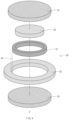
FIG. 4 is an exploded perspective view illustrating atop cap 2 according to an embodiment of the present invention.FIG. 5 is a lateral cross-sectional view illustrating thetop cap 2 in a state in which current is not cut off according to an embodiment of the present invention.FIG. 6 is a lateral cross-sectional view illustrating thetop cap 2 in a state in which current is cut off according to an embodiment of the present invention. The same or similar description as or to the foregoing description may also apply to this embodiment. - A third
conductive part 31 may overlap each of a firstconductive part 10 and a secondconductive part 20 when viewed from above. For example, the thirdconductive part 31 may be disposed between the firstconductive part 10 and the secondconductive part 20 in order to electrically connect the firstconductive part 10 to the secondconductive part 20, and include a portion overlapping each of the firstconductive part 10 and the secondconductive part 20 when viewed from above. - An edge of an
intermediate layer part 30 may have a circular shape, and the thirdconductive part 31 may have an annular shape when viewed from above. For example, the edge of theintermediate layer part 30 may correspond to an edge of agasket part 32, and theintermediate layer part 30 may have the edge having a circular shape so as to be seated on acylindrical can 3. The thirdconductive part 31 may have an annular shape, and as the thirdconductive part 31 is coupled to an inner surface of thegasket part 32, a through-region 33 having an annular shape may be defined. In other words, the thirdconductive part 31 may be disposed to be in contact with a portion corresponding to a minor radius of the through-region 33 of thegasket part 32. A volume of the through-region 33 may be pre-designed. The shape of the thirdconductive part 31 described above is not limited to the annular shape, and the thirdconductive part 31 may be embodied in various forms according to a design. - The third
conductive part 31 may have a lower melting point than a melting point of each of the firstconductive part 10 and the secondconductive part 20. For example, when overcurrent flows through the firstconductive part 10, the secondconductive part 20, and the thirdconductive part 31, the thirdconductive part 31 may be melted, but the firstconductive part 10 and the secondconductive part 20 may not be melted. As described above, only the thirdconductive part 31 may be melted due to the overcurrent, and thegasket part 32 may be disposed between the firstconductive part 10 and the secondconductive part 20 to support the firstconductive part 10 and the secondconductive part 20. Thus, this may be advantageous in terms of structural stability. Even when the thirdconductive part 31 is melted due to the overcurrent, the shape of thegasket part 32 may be maintained so that an overall outer shape and a position of theintermediate layer part 30 are maintained without being changed. - As the third
conductive part 31 is melted, the contact between the thirdconductive part 31 and the firstconductive part 10 or the secondconductive part 20 may be released. For example, when a temperature of the thirdconductive part 31 is higher than a predetermined temperature due to the overcurrent, the thirdconductive part 31 may be melted to decrease a height thereof so that the contact between the thirdconductive part 31 and the firstconductive part 10 or the secondconductive part 20 is released. In other words, when the temperature of the thirdconductive part 31 is higher than the predetermined temperature, and thus the thirdconductive part 31 is melted, an electrical connection between the firstconductive part 10 and the secondconductive part 20 may be cut off. For another example, when overcurrent does not flow, and thus the temperature of the thirdconductive part 31 is lower than the predetermined temperature, the thirdconductive part 31 may not be melted, and the contact may be maintained. In other words, when the temperature of the thirdconductive part 31 is lower than the predetermined temperature, and thus the thirdconductive part 31 is not melted, the electrical connection between the firstconductive part 10 and the secondconductive part 20 may be maintained through the thirdconductive part 31. - As described above, when the overcurrent flows, the third
conductive part 31 may be melted so that the contact between the thirdconductive part 31 and the firstconductive part 10 or the secondconductive part 20 is released to cut off the electrical connection therebetween. Accordingly, the overcurrent may be cut off simply and effectively. -
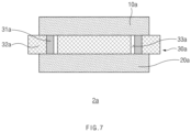
FIG. 7 is a lateral cross-sectional view illustrating atop cap 2a according to another embodiment of the present invention. The same or similar description as or to the foregoing description may also apply to this embodiment. - The
top cap 2a may include a thirdconductive part 31a. A through-region 31a may be defined between the thirdconductive part 31a and agasket part 32a. As illustrated inFIG. 7 , the through-region 31a may be defined at a different position from the through-region 31 inFIG. 3 or5 . - As the third
conductive part 31a is, as illustrated inFIG. 7 , disposed to have a larger radius than a radius of the thirdconductive part 31, a contact area with each of a firstconductive part 10a and a secondconductive part 20a may be increased. - When the contact area between the third
conductive part 31a and each of the firstconductive part 10a and the secondconductive part 20a is increased, current may more effectively flow. -
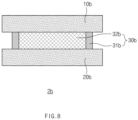
FIG. 8 is a lateral cross-sectional view illustrating atop cap 2b according to another embodiment of the present invention. The same or similar description as or to the foregoing description may also apply to this embodiment. - The
top cap 2b may cover an opened upper portion of acylindrical can 3. For example, a secondconductive part 20b of thetop cap 2b may be coupled and fixed to an inner surface of thecylindrical can 3. In this case, even when theintermediate layer part cylindrical can 3, the opened upper portion of thecylindrical can 3 may be covered. - A third
conductive part 32b may be disposed to surround at least a portion of an outer surface of agasket part 32b. For example, the thirdconductive part 31b may be disposed while surrounding the outer surface of thegasket part 32b, and be in contact with each of a firstconductive part 10b and the secondconductive part 20b. - As described above, a volume of the
gasket part 32b may be reduced to lead to an advantage in production, and as the secondconductive part 20b is fixed to the inner surface of thecylindrical can 3, a space in which the thirdconductive part 31b is capable of flowing when the thirdconductive part 31b is melted may be secured without a separate process. In addition, a size of the thirdconductive part 31b may be adjusted according to a design to adjust a degree of current conductivity. - Although the present invention has been described with reference to the limited embodiments and drawings, the present invention is not limited thereto and may be variously implemented by those of ordinary skill in the art to which the present invention pertains, within the technical idea of the present invention and an equivalent of the appended claims.
-
- 1: Cylindrical type secondary battery
- 2, 2a, 2b: Top cap
- 3: Cylindrical can
- 3-1: Seating part
- 4: Electrode assembly
- 10, 10a, 10b: First conductive part
- 20, 20a, 20b: Second conductive part
- 30, 30a, 30b: Intermediate layer part
- 31, 31a, 31b: Third conductive part
- 32, 32a, 32b: Gasket part
- 33, 33a: Through-region
Claims (13)
- A cylindrical type secondary battery comprising:a cylindrical can configured to accommodate an electrode assembly; anda top cap provided to cover an opened upper portion of the cylindrical can,wherein the top cap comprises:a first conductive part;a second conductive part disposed below the first conductive part and electrically connected to the electrode assembly; andan intermediate layer part comprising a third conductive part disposed between the first conductive part and the second conductive part to be in contact with each of the first conductive part and the second conductive part, wherein, when a temperature of the third conductive part is a predetermined temperature or higher, the third conductive part is melted so that the contact between the third conductive part and the first conductive part or the second conductive part is released,wherein the intermediate layer part comprises a gasket part disposed between the first conductive part and the second conductive part, and configured to define a through-region between the gasket part and the third conductive part in a state in which the third conductive part is disposed to pass through the intermediate layer part.
- The cylindrical type secondary battery of claim 1, wherein the intermediate layer part comprises the gasket part configured to surround the third conductive part with spacing from the third conductive part, and
when the temperature of the third conductive part is the predetermined temperature or higher, the third conductive part is melted to decrease a height thereof so that the contact is released. - The cylindrical type secondary battery of claim 1, wherein the third conductive part has a lower melting point than a melting point of each of the first conductive part and the second conductive part.
- The cylindrical type secondary battery of claim 1, wherein the third conductive part overlaps each of the first conductive part and the second conductive part when viewed from above.
- The cylindrical type secondary battery of claim 1, wherein the cylindrical can comprises a seating part provided on an inner surface thereof so that the intermediate layer part is seated on the seating part, and
wherein, as the intermediate layer part is seated on the seating part, the top cap covers the opened upper portion. - The cylindrical type secondary battery of claim 1, wherein an edge of the intermediate layer part has a circular shape when viewed from above, and
the third conductive part has an annular shape when viewed from above. - The cylindrical type secondary battery of claim 1, wherein the intermediate layer part comprises the gasket part in which a through-region having an annular shape is defined, and
the third conductive part is disposed to be in contact with a portion corresponding to a minor radius of the through-region of the gasket part when viewed from above. - The cylindrical type secondary battery of claim 1, wherein the first conductive part and the second conductive part are electrically connected to each other through the third conductive part when the temperature of the third conductive part is lower than the predetermined temperature, and
the electrical connection is cut off when the third conductive part reaches at the predetermined temperature or higher to be melted. - The cylindrical type secondary battery of claim 1, wherein the third conductive part is provided to be in surface contact with each of the first conductive part and the second conductive part.
- A top cap configured to cover an upper portion of a cylindrical can provided so that an electrode assembly is accommodated therein, the top cap comprising:a first conductive part;a second conductive part disposed below the first conductive part and electrically connected to the electrode assembly; andan intermediate layer part,wherein the intermediate layer part comprises:a third conductive part disposed between the first conductive part and the second conductive part to be in contact with each of the first conductive part and the second conductive part, wherein, when a temperature of the third conductive part is a predetermined temperature or higher, the third conductive part is melted so that the contact between the third conductive part and the first conductive part or the second conductive part is released; anda gasket part configured to define a through-region between the gasket part and the intermediate layer part in a state in which the third conductive part is disposed to pass through the intermediate layer part.
- The top cap of claim 10, wherein the intermediate layer part comprises the gasket part comprising a portion configured to surround the third conductive part with spacing from the third conductive part, and
when the temperature of the third conductive part is the predetermined temperature or higher, the third conductive part is melted to decrease a height thereof so that the contact is released. - The top cap of claim 10, wherein the third conductive part has a lower melting point than a melting point of each of the first conductive part and the second conductive part.
- The top cap of claim 10, wherein the intermediate layer part comprises the gasket part provided so that the third conductive part is coupled to an outer surface thereof, and
when the temperature of the third conductive part is the predetermined temperature or higher, the third conductive part is melted to decrease a height thereof so that the contact is released.
Applications Claiming Priority (3)
| Application Number | Priority Date | Filing Date | Title |
|---|---|---|---|
| KR20220127432 | 2022-10-05 | ||
| KR1020230128587A KR20240047914A (en) | 2022-10-05 | 2023-09-25 | Cylindrical secondary battery including top cap |
| PCT/KR2023/015277 WO2024076157A1 (en) | 2022-10-05 | 2023-10-05 | Cylindrical secondary battery comprising top cap |
Publications (2)
| Publication Number | Publication Date |
|---|---|
| EP4576405A1 true EP4576405A1 (en) | 2025-06-25 |
| EP4576405A4 EP4576405A4 (en) | 2026-03-25 |
Family
ID=90608364
Family Applications (1)
| Application Number | Title | Priority Date | Filing Date |
|---|---|---|---|
| EP23875220.8A Pending EP4576405A4 (en) | 2022-10-05 | 2023-10-05 | CYLINDRICAL SECONDARY BATTERY WITH TOP CAP |
Country Status (4)
| Country | Link |
|---|---|
| EP (1) | EP4576405A4 (en) |
| JP (1) | JP2025530544A (en) |
| CN (1) | CN119999006A (en) |
| WO (1) | WO2024076157A1 (en) |
Family Cites Families (15)
| Publication number | Priority date | Publication date | Assignee | Title |
|---|---|---|---|---|
| JP3754795B2 (en) * | 1997-03-27 | 2006-03-15 | 内橋エステック株式会社 | Temperature fuse mounting structure for secondary battery and temperature fuse with insulating spacer |
| JP3754794B2 (en) * | 1997-03-29 | 2006-03-15 | 内橋エステック株式会社 | Temperature fuse and temperature fuse mounting structure for secondary battery |
| JP2001160382A (en) * | 1999-12-02 | 2001-06-12 | Sanyo Electric Co Ltd | Battery sealing body |
| JP2008027668A (en) * | 2006-07-19 | 2008-02-07 | Sony Corp | battery |
| JP2009289732A (en) * | 2008-01-31 | 2009-12-10 | Panasonic Corp | Secondary battery |
| CN101626067B (en) * | 2008-07-10 | 2013-01-16 | 深圳市比克电池有限公司 | Connection structure of cell polar ear and cover plate |
| KR101132115B1 (en) * | 2010-05-31 | 2012-04-05 | 삼성에스디아이 주식회사 | Case of secondary battery and secondary battery involving the same |
| CN202251234U (en) * | 2011-09-19 | 2012-05-30 | 广东天恒液压机械有限公司 | Support and guide device for hydraulic cylinder made of melt-adhered special material |
| JP5899495B2 (en) * | 2011-12-28 | 2016-04-06 | パナソニックIpマネジメント株式会社 | Cylindrical lithium-ion battery |
| WO2014129462A1 (en) * | 2013-02-20 | 2014-08-28 | タイコエレクトロニクスジャパン合同会社 | Opening sealing body |
| KR102483157B1 (en) * | 2018-02-12 | 2022-12-30 | 주식회사 엘지에너지솔루션 | Secondary battery |
| KR102622370B1 (en) * | 2018-08-16 | 2024-01-09 | 주식회사 엘지에너지솔루션 | Rechargeable battery |
| KR102573294B1 (en) | 2018-10-27 | 2023-08-30 | 후아웨이 테크놀러지 컴퍼니 리미티드 | Individual merge list for subblock merge candidates and intra-inter technology harmonization for video coding |
| JP7241571B2 (en) * | 2019-03-07 | 2023-03-17 | Littelfuseジャパン合同会社 | sealing body |
| KR102533785B1 (en) | 2021-03-10 | 2023-05-30 | 부산가톨릭대학교 산학협력단 | Foot-ankle biofeedback device |
-
2023
- 2023-10-05 CN CN202380069321.4A patent/CN119999006A/en active Pending
- 2023-10-05 WO PCT/KR2023/015277 patent/WO2024076157A1/en not_active Ceased
- 2023-10-05 EP EP23875220.8A patent/EP4576405A4/en active Pending
- 2023-10-05 JP JP2025517913A patent/JP2025530544A/en active Pending
Also Published As
| Publication number | Publication date |
|---|---|
| JP2025530544A (en) | 2025-09-11 |
| WO2024076157A1 (en) | 2024-04-11 |
| EP4576405A4 (en) | 2026-03-25 |
| CN119999006A (en) | 2025-05-13 |
Similar Documents
| Publication | Publication Date | Title |
|---|---|---|
| CN111916587B (en) | Secondary battery top cover assembly, secondary battery and automobile | |
| KR100599598B1 (en) | Secondary Battery, Electrode Assembly and Current Collecting Plate Used in the Same | |
| EP2587568B1 (en) | Sealing plug and energy storage element | |
| US9979005B2 (en) | Rechargeable battery having short circuit member | |
| EP3799146B1 (en) | Top cover assembly and secondary battery | |
| US20230011273A1 (en) | Rechargeable battery | |
| EP3518305B1 (en) | Secondary battery | |
| US20160343997A1 (en) | Electrical storage device | |
| JP6228127B2 (en) | Cylindrical storage battery and storage battery module | |
| US9887412B2 (en) | Rechargeable battery having upper insulator member | |
| JP5203729B2 (en) | Secondary battery and battery module | |
| CN208256820U (en) | Secondary cell | |
| EP4145611B1 (en) | Secondary battery | |
| US20050214641A1 (en) | Cap assembly and secondary battery using the same | |
| EP4576405A1 (en) | Cylindrical secondary battery comprising top cap | |
| EP3958390A1 (en) | Cylindrical secondary battery comprising positive electrode tab fixing member | |
| KR20150041505A (en) | Rechargeable battery having connecting member | |
| US12512540B2 (en) | Cylindrical secondary cell lid comprising multiple recessed contact portions | |
| CN221328055U (en) | Button type secondary battery | |
| KR20240047914A (en) | Cylindrical secondary battery including top cap | |
| KR20220114977A (en) | Button type secondary battery | |
| KR101683203B1 (en) | Rechargeable battery | |
| JP2015187965A (en) | secondary battery | |
| EP4391164A1 (en) | Top cap assembly and button-type secondary battery including same | |
| KR101256061B1 (en) | Rechargeable battery |
Legal Events
| Date | Code | Title | Description |
|---|---|---|---|
| STAA | Information on the status of an ep patent application or granted ep patent |
Free format text: STATUS: THE INTERNATIONAL PUBLICATION HAS BEEN MADE |
|
| PUAI | Public reference made under article 153(3) epc to a published international application that has entered the european phase |
Free format text: ORIGINAL CODE: 0009012 |
|
| STAA | Information on the status of an ep patent application or granted ep patent |
Free format text: STATUS: REQUEST FOR EXAMINATION WAS MADE |
|
| 17P | Request for examination filed |
Effective date: 20250321 |
|
| AK | Designated contracting states |
Kind code of ref document: A1 Designated state(s): AL AT BE BG CH CY CZ DE DK EE ES FI FR GB GR HR HU IE IS IT LI LT LU LV MC ME MK MT NL NO PL PT RO RS SE SI SK SM TR |
|
| DAV | Request for validation of the european patent (deleted) | ||
| DAX | Request for extension of the european patent (deleted) | ||
| A4 | Supplementary search report drawn up and despatched |
Effective date: 20260220 |
|
| RIC1 | Information provided on ipc code assigned before grant |
Ipc: H01M 50/581 20210101AFI20260216BHEP Ipc: H01M 50/107 20210101ALI20260216BHEP Ipc: H01M 50/152 20210101ALI20260216BHEP Ipc: H01M 50/186 20210101ALI20260216BHEP |