EP4576370A1 - Battery case, battery pack, and electric-powered apparatus - Google Patents
Battery case, battery pack, and electric-powered apparatus Download PDFInfo
- Publication number
- EP4576370A1 EP4576370A1 EP24212029.3A EP24212029A EP4576370A1 EP 4576370 A1 EP4576370 A1 EP 4576370A1 EP 24212029 A EP24212029 A EP 24212029A EP 4576370 A1 EP4576370 A1 EP 4576370A1
- Authority
- EP
- European Patent Office
- Prior art keywords
- detachment
- battery
- case
- slider
- outer frame
- Prior art date
- Legal status (The legal status is an assumption and is not a legal conclusion. Google has not performed a legal analysis and makes no representation as to the accuracy of the status listed.)
- Pending
Links
Images

Classifications
-
- H—ELECTRICITY
- H01—ELECTRIC ELEMENTS
- H01M—PROCESSES OR MEANS, e.g. BATTERIES, FOR THE DIRECT CONVERSION OF CHEMICAL ENERGY INTO ELECTRICAL ENERGY
- H01M50/00—Constructional details or processes of manufacture of the non-active parts of electrochemical cells other than fuel cells, e.g. hybrid cells
- H01M50/20—Mountings; Secondary casings or frames; Racks, modules or packs; Suspension devices; Shock absorbers; Transport or carrying devices; Holders
- H01M50/204—Racks, modules or packs for multiple batteries or multiple cells
-
- H—ELECTRICITY
- H01—ELECTRIC ELEMENTS
- H01M—PROCESSES OR MEANS, e.g. BATTERIES, FOR THE DIRECT CONVERSION OF CHEMICAL ENERGY INTO ELECTRICAL ENERGY
- H01M50/00—Constructional details or processes of manufacture of the non-active parts of electrochemical cells other than fuel cells, e.g. hybrid cells
- H01M50/20—Mountings; Secondary casings or frames; Racks, modules or packs; Suspension devices; Shock absorbers; Transport or carrying devices; Holders
- H01M50/244—Secondary casings; Racks; Suspension devices; Carrying devices; Holders characterised by their mounting method
-
- H—ELECTRICITY
- H01—ELECTRIC ELEMENTS
- H01M—PROCESSES OR MEANS, e.g. BATTERIES, FOR THE DIRECT CONVERSION OF CHEMICAL ENERGY INTO ELECTRICAL ENERGY
- H01M50/00—Constructional details or processes of manufacture of the non-active parts of electrochemical cells other than fuel cells, e.g. hybrid cells
- H01M50/20—Mountings; Secondary casings or frames; Racks, modules or packs; Suspension devices; Shock absorbers; Transport or carrying devices; Holders
- H01M50/262—Mountings; Secondary casings or frames; Racks, modules or packs; Suspension devices; Shock absorbers; Transport or carrying devices; Holders with fastening means, e.g. locks
-
- H—ELECTRICITY
- H01—ELECTRIC ELEMENTS
- H01M—PROCESSES OR MEANS, e.g. BATTERIES, FOR THE DIRECT CONVERSION OF CHEMICAL ENERGY INTO ELECTRICAL ENERGY
- H01M50/00—Constructional details or processes of manufacture of the non-active parts of electrochemical cells other than fuel cells, e.g. hybrid cells
- H01M50/20—Mountings; Secondary casings or frames; Racks, modules or packs; Suspension devices; Shock absorbers; Transport or carrying devices; Holders
- H01M50/289—Mountings; Secondary casings or frames; Racks, modules or packs; Suspension devices; Shock absorbers; Transport or carrying devices; Holders characterised by spacing elements or positioning means within frames, racks or packs
- H01M50/293—Mountings; Secondary casings or frames; Racks, modules or packs; Suspension devices; Shock absorbers; Transport or carrying devices; Holders characterised by spacing elements or positioning means within frames, racks or packs characterised by the material
-
- H—ELECTRICITY
- H01—ELECTRIC ELEMENTS
- H01M—PROCESSES OR MEANS, e.g. BATTERIES, FOR THE DIRECT CONVERSION OF CHEMICAL ENERGY INTO ELECTRICAL ENERGY
- H01M50/00—Constructional details or processes of manufacture of the non-active parts of electrochemical cells other than fuel cells, e.g. hybrid cells
- H01M50/30—Arrangements for facilitating escape of gases
- H01M50/35—Gas exhaust passages comprising elongated, tortuous or labyrinth-shaped exhaust passages
- H01M50/367—Internal gas exhaust passages forming part of the battery cover or case; Double cover vent systems
-
- Y—GENERAL TAGGING OF NEW TECHNOLOGICAL DEVELOPMENTS; GENERAL TAGGING OF CROSS-SECTIONAL TECHNOLOGIES SPANNING OVER SEVERAL SECTIONS OF THE IPC; TECHNICAL SUBJECTS COVERED BY FORMER USPC CROSS-REFERENCE ART COLLECTIONS [XRACs] AND DIGESTS
- Y02—TECHNOLOGIES OR APPLICATIONS FOR MITIGATION OR ADAPTATION AGAINST CLIMATE CHANGE
- Y02E—REDUCTION OF GREENHOUSE GAS [GHG] EMISSIONS, RELATED TO ENERGY GENERATION, TRANSMISSION OR DISTRIBUTION
- Y02E60/00—Enabling technologies; Technologies with a potential or indirect contribution to GHG emissions mitigation
- Y02E60/10—Energy storage using batteries
Definitions
- the present disclosure relates to the field of batteries, and in particular to a battery case, a battery pack, and an electric-powered apparatus.
- a battery pack is a unit formed by a plurality of battery modules being assembled to each other and is configured to store and supply electrical energy.
- the battery pack is a higher-level component of a battery system.
- the battery pack is usually formed by one or more battery modules, connectors, a battery management system, a heat dissipation system, electrical interfaces, and a housing. Battery packs are widely used in electric vehicles, hybrid vehicles and other vehicles.
- the battery pack is an essential component of an electric energy system and provides a higher level of electrical energy storage and management to meet requirements of various applications.
- a battery case in a first aspect, includes: a battery tray bracket; a case body; and a slider detachment member.
- the case body has a case outer frame and a support beam.
- the case outer frame defines a battery compartment inside the case outer frame.
- the case outer frame and/or the support beam defines with an anti-detachment slide slot.
- the support beam is fixedly connected to the case outer frame.
- the slider detachment member is slidably arranged in the anti-detachment slide slot.
- An anti-detachment snap portion of the slider detachment member is configured to constrain and fix the battery tray bracket to the case outer frame and the support beam.
- a battery pack in a second aspect, includes the battery case as described in the above and a battery module, mounted and fixed to the battery tray bracket of the battery case.
- the battery module includes: a module positioning bracket and one or more cells.
- the one or more cells are evenly distributed having an equal interval; each of the one or more cells is inserted in the module positioning bracket, and each of the one or more cells is capable of exchanging heat with the pressure relief channel of the battery case.
- an electric-powered apparatus in a third aspect, includes the battery pack as described in the above.
- the tray bracket of the battery can be firmly fixed in the case body.
- the bolt in the art for securing and attaching is replaced.
- the technical problem of the battery pack being loosened and the battery having short-circuits and being on fire, caused by the bolt being threadedly failed may be avoided, ensuring the battery pack to be used safely and stably.
- the case body of the battery case does not need to be processed to define holes to be arranged with rivet nuts. Therefore, methods of processing the battery case and the battery pack are simplified, the battery case and the battery pack can be processed and assembled more conveniently and efficiently.
- each of the one or more cells 4 is a cylindrical battery.
- Each cell 4 has a positive-electrode end surface, a negative-electrode end surface, and an arc-shaped battery circumferential surface.
- the positive-electrode end surface and the negative-electrode end surface are respectively disposed on two opposite sides of the battery circumferential surface.
- a direction from the negative-electrode end surface towards the positive-electrode end surface is defined as a height direction of the cell 4.
- the one or more cells 4 are distributed having an equal interval.
- the one or more cells 4 are connected in series and in parallel to each other. When the one or more cells 4 are distributed having the equal interval, negative-electrode end surfaces of the one or more cells 4 are in a same plane, and the one or more cells 4 have a same height direction.
- the battery module further includes a module positioning bracket 5, the module positioning bracket 5 is arranged with one or more assembling stations.
- Each of the one or more assembling stations is arranged correspondingly with a respective one of the one or more cells 4.
- a shape and a size of the assembling station matches a shape and a size of the respective cell 4, enabling each cell 4 to be inserted in the respective assembling station of the module positioning bracket 5.
- the battery case includes a battery tray bracket 1, the battery tray bracket 1 has a tray body 11, the tray body 11 defines a tray cavity 12 therein.
- the battery module is mounted and fixed to the tray cavity 12 of the battery tray bracket 1.
- a side of the module positioning bracket 5 of the battery module abuts against a cavity wall of the tray cavity 12. In this way, the battery module can be securely fixed to the battery tray bracket 1.
- a side of the tray body 11 near an opening of the tray cavity 12 protrudes outwardly to form a tray support portion 13.
- the tray support portion 13 extends along a peripheral side of the tray body 11.
- the battery case further includes a case body 2 and a slider detachment member 3.
- the case body 2 has a case outer frame 21 and a support beam 22.
- the case outer frame 21 defines a battery compartment 23 therein.
- the support beam 22 is fixedly connected to the case outer frame 21.
- the case outer frame 21 includes a case bottom plate, two outer cross frames 211 opposite to each other, and two outer vertical frames 212 opposite to each other.
- the two outer vertical frames 212 are disposed between the two outer cross frames 211. Two ends of each outer vertical frame 212 are respectively fixedly connected to the two outer cross frames 211.
- the two outer cross frames 211 and the two outer vertical frames 212 are all fixedly connected to the case bottom plate.
- the case bottom plate, the two outer cross frames 211 and the two outer vertical frames 212 cooperatively define the battery compartment 23.
- the support beam 22 is parallel to the outer vertical frames 212 and is fixedly connected to the outer cross frames 211.
- the fixed connection may be welded connection, snap connection, or combination of the welded connection and the snap connection.
- the support beam 22 defines an anti-detachment slide slot 24, located at a side of the support beam 22 near the battery compartment 23.
- the anti-detachment slide slot 24 extends along a length direction of the support beam 22. In some embodiments, the anti-detachment slide slot 24 extends through the support beam 22.
- the slider detachment member 3 is slidably arranged in the anti-detachment slide slot 24. An anti-detachment snap portion 31 of the slider detachment member 3 may constrain and fix the battery tray bracket 1 to the case outer frame 21 and the support beam 22.
- the tray support portion 13 of the battery tray bracket 1 abuts against the case outer frame 21 and the support beam 22.
- the slider detachment member 3 is then slidably connected to the anti-detachment slide slot 24, and the anti-detachment snap portion 31 of the slider detachment member 3 is snapped to the tray support portion 13 of the battery tray bracket 1.
- the tray support portion 13 of the battery tray bracket 1 is tightly clamped between the support beam 22 and the anti-detachment snap portion 31 of the slider detachment member 3, such that the battery tray bracket 1 is completely constrained to the case body 2, and stable assembling between the battery tray bracket 1 and the case body 2 can be achieved.
- each of two support beams 22 acting on the two opposite sides of the battery tray bracket 1 is arranged with the slider detachment member 3, respectively.
- the slider detachment member 3 is arranged with the slider detachment member 3.
- the outer vertical frame 212 of the case outer frame 21 is arranged with the anti-detachment slide slot 24, such that the tray support portion 13 that is subjected to the outer vertical frame 212 can be snapped and tightly clamped by the slider detachment members 3.
- the anti-detachment slide slot 24 is not limited to be arranged at the support beam 22 and the outer vertical frame 212 of the case outer frame 21. According to assembly requirements and design demands, positions and the number of the anti-detachment slide slots 24 arranged on the case body 2 can be adjusted.
- the anti-detachment slide slot 24 may further be arranged on the outer cross frame 211 of the case outer frame 21. In this way, each of the support beam 22, the outer cross frame 211 of the case outer frame 21, the outer vertical frame 212 of the case outer frame 21 is arranged with the anti-detachment slide slot 24. Therefore, the peripheral side of the battery tray bracket 1 can be snapped by one or more slider detachment members 3, and the battery tray bracket 1 is subjected to forces more balancedly.
- the anti-detachment slide slot 24 is arranged only on the support beam 22 of the case body 2 or only on the case outer frame 21 of the case body 2 or arranged on the support beam 22 and the outer cross frame 211 of the case outer frame 21.
- the slider detachment member 3 is arranged to restrain and fix the battery tray bracket 1 on the case outer frame 21 and the support beam 22. In this way, the technical problem of inconvenient disassembling and insecure assembling, caused by failure of threads of bolts and other fasteners having threaded structures, can be avoided; and in addition, it is ensured that the battery pack can be used stably and safely. Furthermore, a drilling process is simplified. An arrangement position of the slider detachment member 3 can be adjusted along a length extension direction of the anti-detachment slide slot 24; or the number of slider detachment members 3 can be increased or decreased in any case in the anti-detachment slide slot 24. Therefore, the battery case and the battery pack can be assembled more flexibly and conveniently.
- a weight reduction cavity 25 may be defined in the support beam 22.
- the battery tray bracket 1 defines a positioning and anti-detachment slot 15.
- the positioning and anti-detachment slot 15 extends from a side edge of the tray support portion 13 towards the tray cavity 12.
- the anti-detachment snap portion 31 of the slider detachment member 3 is snapped into the positioning and anti-detachment slot 15.
- one or more positioning and anti-detachment slots 15 are defined and are evenly distributed along an extension direction of the tray support portion 13.
- the slider detachment member 3 is assembled to the anti-detachment slide slot 24 and slides along the length direction of the anti-detachment slide slot 24 until the anti-detachment snap portion 31 of the slider detachment member 3 is snap-fitted into the designated anti-detachment slot 15. In this way, positioning can be achieved rapidly, and the assembling is performed more efficiently and conveniently.
- the anti-detachment slot 15 can limit a translational displacement of the slider detachable member 3 along the length direction of the anti-detachment slide slot 24.
- the slider detachment member 3 is prevented from moving along the length direction of the anti-detachment slide slot 24, and assembling stability between the slider detachment member 3, the battery tray bracket 1 and the case body 2 is improved.
- the battery case further includes an elastic cushioning member 6.
- the elastic cushioning member 6 is disposed between the case body 2 and the battery tray bracket 1.
- the elastic cushioning member 6 may be made of silicone or a plastic material or a rubber material. Elastic performance of the elastic cushioning member 6 cushions an impact generated during the battery tray bracket 1 being assembled to the case body 2, preventing wear and noise caused by the battery tray bracket 1 and the case body 2 rigidly colliding with each other. In addition, the elastic performance of the elastic cushioning member 6 prevents collision and noise of the battery tray bracket 1 and the case body 2 due to vibration.
- the elastic cushioning member 6 when a force is applied to the tray support portion 13 of the battery tray bracket 1 in a direction perpendicular to a top surface of the tray support portion 13, the elastic cushioning member 6 is excessively compressed, the battery module and the battery tray bracket 1 are temporarily lowered in the height direction, ensuring the slider detachable member 3 to translationally displace along the length direction of the anti-detachment slide slot 24.
- the elastic cushioning member 6 can increase a pressure of the anti-detachment snap portion 31 applying on the tray support portion 13, such that friction between the anti-detachment snap portion 31 and the tray support portion 13 is increased, and stability of the assembling between the battery tray bracket 1 and the case body 2 is improved.
- a cushioning embedding groove 26 is defined in each of the case outer frame 21 and the support beam 22.
- the elastic cushioning member 6 is embedded inside the cushioning embedding groove 26.
- a width of the elastic cushioning member 6 fits a groove width of the cushioning embedding groove 26.
- the groove width of the cushioning embedding groove 26 is greater than the width of the elastic cushioning member 6.
- a slot opening of the anti-detachment slide slot 24 in a slot depth direction is defined as a top opening of the anti-detachment slide slot 24; and a slot opening of the anti-detachment slide slot 24 in the length direction is defined as an end opening of the anti-detachment slide slot 24.
- the cushioning embedding groove 26 is located at a side of the top opening of the anti-detachment slide slot 24, and the groove length direction of the cushioning embedding groove 26 is the same as the length direction of the anti-detachment slide slot 24.
- the anti-detachment slide slot 24 has an extension cavity 241 extending in a width direction of the anti-detachment slide slot 24. That is, the anti-detachment slide slot 24 includes a slot body and the extension cavity 241. The extension cavity 241 is located on a side of the slot body near a bottom of the anti-detachment slide slot 24. The slot body and the extension cavity 241 are communicated with each other. When one extension cavity 241 is defined, the anti-detachment slide slot 24 is L-shaped. When two extension cavities 241 are defined, the two extension cavities 241 are located at two opposite sides of the slot body, and the anti-detachment slide slot 24 is inverted T-shaped.
- the slider detachment member 3 further includes a slider body 32 and an extension snap portion 33.
- the extension snap portion 33 is protruding from the slider body 32 towards the extension cavity 241.
- the anti-detachment snap portion 31 and the extension snap portion 33 are respectively located on two opposite sides of the slider body 32.
- the anti-detachment snap portion 31 is fixedly connected to the slider body 32.
- the anti-detachment snap portion 31, the slider body 32, and the extension snap portion 33 are integrally formed with each other as a one-piece structure.
- each extension snap portion 33 corresponds to a respective one extension cavity 241.
- one anti-detachment snap portion 31 may be arranged, i.e., the anti-detachment snap portion 31 extends towards a side of the slider body 32, and the anti-detachment snap portion 31 and the slider body 32 cooperatively form the L shape.
- two anti-detachment snap portions 31 may be arranged, and the two anti-detachment snap portions 31 respectively extend from two opposite sides of the slider body 32, and the two anti-detachment snap portions 31 and the slider body 32 cooperatively form a T shape.
- the slider detachment member 3 can firmly and stably fix the battery tray bracket 1 and the battery module to the battery case, thread failure of the bolts after long-term use may be avoided.
- the technical problem of the battery module being lifted up by the atmospheric pressure, caused by an instantaneous increase in the pressure inside the battery case exceeding an axial bearing capacity of the bolt, can be avoided.
- a stable and solid structure and assembly for the battery module is provided, and the battery module and the battery pack can be used more stably and safely.
- the slider detachment member 3 may receive friction from a single side and is deflected, such that the anti-detachment snap portion 31 of the slider detachment member 3 may snap, in an inclined manner, to the tray support portion 13 of the battery tray bracket 1, a force application surface between the anti-detachment snap portion 31 and the tray support portion 13 is reduced; or the anti-detachment snap portion 31 cannot be embedded into the positioning and anti-detachment slot 15, leading to assembling failure.
- a slot bottom of the anti-detachment slide slot 24 is arranged with a guide rib 27.
- the guide rib 27 extends in the length direction of the anti-detachment slide slot 24.
- the slider detachment member 3 defines a guide opening 34 that is slidably mated with the guide rib 27.
- the guide opening 34 extends through the slider body 32 of the slider detachment member 3.
- a shape and a size of the guide opening 34 match a shape and a size of the guide rib 27.
- an end of the guide rib 27 near the end opening of the anti-detachment slide slot 24 is arranged with a disassembling station 28.
- a spacing is defined between the end of the guide rib 27 and the end opening of the anti-detachment slide slot 24, rather than the end of the guide rib 27 extending to reach the end opening of the anti-detachment slide slot 24.
- the slider detachment member 3 may be deflected/rotated in the disassembling station 28, such that a mounting angle of the slider detachment member 3 can be adjusted prior to sliding. That is, after the slider detachment member 3 is placed into the anti-detachment slide slot 24 from the top opening of the anti-detachment slide slot 24, the slider detachment member 3 is deflected by a certain angle to enable the guide opening 34 of the slider detachment member 3 to be aligned with the guide rib 27 in the anti-detachment slide slot 24.
- the extension snap portion 33 of the slider detachment member 3 is completely snapped to the extension cavity 241 of the anti-detachment slide slot 24.
- the cell 4 of the battery module generates a large amount of heat after a long-term use, and when any cell 4 of the battery module has the thermal runaway, the cell 4 having the thermal runaway may release high temperature hot air and high temperature substances.
- the present disclosure further provides following embodiments.
- the battery tray bracket 1, the case outer frame 21, and the support beam 22 cooperatively define a pressure relief channel. That is, when the tray support portion 13 of the battery tray bracket 1 abuts against the support beam 22, a spacing is defined between the battery tray bracket 1 and a bottom plate of the case outer frame 21. In this way, the battery tray bracket 1, the support beam 22, and the bottom plate of the case outer frame 21 cooperatively define the pressure relief channel; and/or the battery tray bracket 1, the support beam 22, the bottom plate of the case outer frame 21, and the outer vertical frame 212 cooperatively define the pressure relief channel.
- a frame pressure relief chamber is defined in the case outer frame 21, a side wall of the case outer frame 21 defines a communication port. One or more communication ports may be defined. The pressure relief channel is communicated to the frame pressure relief chamber through at least one of the one or more communication ports. A pressure relief valve is arranged on the case outer frame 21.
- the tray body 11 of the battery tray bracket 1 defines a plurality of heat-dissipation and pressure-relief holes 14. Each battery cell 4 is in correspondence with a respective one of the plurality of heat-dissipation and pressure-relief holes 14.
- the heat released by each cell 4 in the battery module or the high temperature hot air and high temperature substances released due to the thermal runaway can be quickly diffused into the pressure relief channel through the corresponding heat-dissipation and pressure-relief holes 14. Therefore, the heat and flowing air are guided, by the pressure relief channel, to the frame pressure relief chamber of the case outer frame 21 and can be ultimately discharged from the pressure relief valve. In this way, the heat or the hot air released from the cell 4 can be timely eliminated, heat spreading of the heat, due to a large amount of heat being accumulated in the battery case, can be avoided, such that the safety of the battery pack is improved.
- the present disclosure further provides an electric-powered apparatus arranged with an apparatus using electric power.
- the electric-powered apparatus may be a transportation means, such as an electric vehicle, an electric cruise ship, an electric bicycle, and so on; or may be an industrial device, such as a handheld drill, an electric wrench, an electric bolt cutter, and so on; or may be an electric-powered device for daily life, such as an electric toy, a game console, a laptop computer, and so on.
Landscapes
- Chemical & Material Sciences (AREA)
- Chemical Kinetics & Catalysis (AREA)
- Electrochemistry (AREA)
- General Chemical & Material Sciences (AREA)
- Battery Mounting, Suspending (AREA)
Abstract
A battery case is provided and includes: a battery tray bracket; a case body; and a slider detachment member. The case body has a case outer frame and a support beam. The case outer frame defines a battery compartment inside the case outer frame. The case outer frame and/or the support beam defines with an anti-detachment slide slot. The support beam is fixedly connected to the case outer frame. The slider detachment member is slidably arranged in the anti-detachment slide slot. An anti-detachment snap portion of the slider detachment member is configured to constrain and fix the battery tray bracket to the case outer frame and the support beam.
Description
- The present disclosure relates to the field of batteries, and in particular to a battery case, a battery pack, and an electric-powered apparatus.
- A battery pack is a unit formed by a plurality of battery modules being assembled to each other and is configured to store and supply electrical energy. The battery pack is a higher-level component of a battery system. The battery pack is usually formed by one or more battery modules, connectors, a battery management system, a heat dissipation system, electrical interfaces, and a housing. Battery packs are widely used in electric vehicles, hybrid vehicles and other vehicles. The battery pack is an essential component of an electric energy system and provides a higher level of electrical energy storage and management to meet requirements of various applications.
- In a first aspect, a battery case is provided and includes: a battery tray bracket; a case body; and a slider detachment member. The case body has a case outer frame and a support beam. The case outer frame defines a battery compartment inside the case outer frame. The case outer frame and/or the support beam defines with an anti-detachment slide slot. The support beam is fixedly connected to the case outer frame. The slider detachment member is slidably arranged in the anti-detachment slide slot. An anti-detachment snap portion of the slider detachment member is configured to constrain and fix the battery tray bracket to the case outer frame and the support beam.
- In a second aspect, a battery pack is provided and includes the battery case as described in the above and a battery module, mounted and fixed to the battery tray bracket of the battery case.
- In some embodiments, the battery module includes: a module positioning bracket and one or more cells. The one or more cells are evenly distributed having an equal interval; each of the one or more cells is inserted in the module positioning bracket, and each of the one or more cells is capable of exchanging heat with the pressure relief channel of the battery case.
- In a third aspect, an electric-powered apparatus is provided and includes the battery pack as described in the above.
- Taking advantages of mating between the slider detachment member and the anti-detachment slot of the case body, the tray bracket of the battery can be firmly fixed in the case body. The bolt in the art for securing and attaching is replaced. In this way, the technical problem of the battery pack being loosened and the battery having short-circuits and being on fire, caused by the bolt being threadedly failed, may be avoided, ensuring the battery pack to be used safely and stably. In addition, the case body of the battery case does not need to be processed to define holes to be arranged with rivet nuts. Therefore, methods of processing the battery case and the battery pack are simplified, the battery case and the battery pack can be processed and assembled more conveniently and efficiently.
-
-
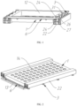
FIG. 1 is a first partial assembling view of a battery case according to some embodiments of the present disclosure. -
FIG. 2 is a second partial assembling view of the battery case according to some embodiments of the present disclosure. -
FIG. 3 is a structural schematic view of a battery tray bracket in the battery case according to some embodiments of the present disclosure. -
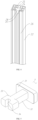
FIG. 4 is a view of a cross section of a support beam of the battery case according to some embodiments of the present disclosure. -
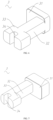
FIG. 5 is a first structural schematic view of a slider detachment member in the battery case according to some embodiments of the present disclosure. -
FIG. 6 is a second structural schematic view of the slider detachment member in the battery case according to some embodiments of the present disclosure. -
FIG. 7 is a third structural schematic view of the slider detachment member in the battery case according to some embodiments of the present disclosure. -
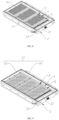
FIG. 8 is an assembled view of an entirety of a battery case arranged with the battery case according to some embodiments of the present disclosure. -
FIG. 9 is a partial assembling view of the battery case arranged with the battery case according to some embodiments of the present disclosure. - Reference numerals in the drawings: 1- battery tray bracket, 11- tray body, 12- tray cavity, 13- tray support portion, 14- heat-dissipation and pressure-relief hole, 15- positioning and anti-detachment slot, 2- case body, 21- case outer frame, 211- outer cross frame, 212- outer vertical frame, 22- support beam, 23- battery compartment, 24- anti-detachment slide slot, 241- extension cavity, 25- weight reduction cavity, 26- cushioning embedding groove, 27-guide rib, 28-disassembling station, 3-slider detachment member, 31- anti-detachment snap portion, 32-slider body, 33-extension snap portion, 34-guide opening, 4-cell, 5-module positioning bracket, 6-elastic cushioning member.
- As shown in
FIGS. 8 and 9 , the present disclosure provides a battery pack including a battery case and a battery module. The battery module includes one or more cells 4. In some embodiments, each of the one or more cells 4 is a cylindrical battery. Each cell 4 has a positive-electrode end surface, a negative-electrode end surface, and an arc-shaped battery circumferential surface. The positive-electrode end surface and the negative-electrode end surface are respectively disposed on two opposite sides of the battery circumferential surface. A direction from the negative-electrode end surface towards the positive-electrode end surface is defined as a height direction of the cell 4. The one or more cells 4 are distributed having an equal interval. The one or more cells 4 are connected in series and in parallel to each other. When the one or more cells 4 are distributed having the equal interval, negative-electrode end surfaces of the one or more cells 4 are in a same plane, and the one or more cells 4 have a same height direction. - In order to ensure that the one or more cells 4 are assembled more stably and compactly, the battery module further includes a
module positioning bracket 5, themodule positioning bracket 5 is arranged with one or more assembling stations. Each of the one or more assembling stations is arranged correspondingly with a respective one of the one or more cells 4. A shape and a size of the assembling station matches a shape and a size of the respective cell 4, enabling each cell 4 to be inserted in the respective assembling station of themodule positioning bracket 5. - As shown in
FIGS. 3 and9 , the battery case includes a battery tray bracket 1, the battery tray bracket 1 has a tray body 11, the tray body 11 defines atray cavity 12 therein. The battery module is mounted and fixed to thetray cavity 12 of the battery tray bracket 1. In some embodiments, a side of themodule positioning bracket 5 of the battery module abuts against a cavity wall of thetray cavity 12. In this way, the battery module can be securely fixed to the battery tray bracket 1. A side of the tray body 11 near an opening of thetray cavity 12 protrudes outwardly to form atray support portion 13. Thetray support portion 13 extends along a peripheral side of the tray body 11. - For an essence of the present embodiment, as shown in
FIGS. 1 ,3 and9 , the battery case further includes acase body 2 and aslider detachment member 3. Thecase body 2 has a caseouter frame 21 and asupport beam 22. The caseouter frame 21 defines abattery compartment 23 therein. Thesupport beam 22 is fixedly connected to the caseouter frame 21. - Specifically, the case
outer frame 21 includes a case bottom plate, twoouter cross frames 211 opposite to each other, and two outervertical frames 212 opposite to each other. The two outervertical frames 212 are disposed between the twoouter cross frames 211. Two ends of each outervertical frame 212 are respectively fixedly connected to the twoouter cross frames 211. The twoouter cross frames 211 and the two outervertical frames 212 are all fixedly connected to the case bottom plate. In addition, the case bottom plate, the twoouter cross frames 211 and the two outervertical frames 212 cooperatively define thebattery compartment 23. In some embodiments, thesupport beam 22 is parallel to the outervertical frames 212 and is fixedly connected to theouter cross frames 211. The fixed connection may be welded connection, snap connection, or combination of the welded connection and the snap connection. - As shown in
FIG. 1 , thesupport beam 22 defines ananti-detachment slide slot 24, located at a side of thesupport beam 22 near thebattery compartment 23. Theanti-detachment slide slot 24 extends along a length direction of thesupport beam 22. In some embodiments, theanti-detachment slide slot 24 extends through thesupport beam 22. Theslider detachment member 3 is slidably arranged in theanti-detachment slide slot 24. Ananti-detachment snap portion 31 of theslider detachment member 3 may constrain and fix the battery tray bracket 1 to the caseouter frame 21 and thesupport beam 22. That is, during assembling the battery tray bracket 1 to thecase body 2, thetray support portion 13 of the battery tray bracket 1 abuts against the caseouter frame 21 and thesupport beam 22. Theslider detachment member 3 is then slidably connected to theanti-detachment slide slot 24, and theanti-detachment snap portion 31 of theslider detachment member 3 is snapped to thetray support portion 13 of the battery tray bracket 1. In this way, thetray support portion 13 of the battery tray bracket 1 is tightly clamped between thesupport beam 22 and theanti-detachment snap portion 31 of theslider detachment member 3, such that the battery tray bracket 1 is completely constrained to thecase body 2, and stable assembling between the battery tray bracket 1 and thecase body 2 can be achieved. In order to ensure that two opposite sides of the battery tray bracket 1 receive forces uniformly, each of twosupport beams 22 acting on the two opposite sides of the battery tray bracket 1 is arranged with theslider detachment member 3, respectively. Of course, as shown inFIG. 9 , when the battery tray bracket 1 is assembled near the outervertical frame 212 of the caseouter frame 21, one of thetray support portions 13 of the battery tray bracket 1 abuts against the outervertical frame 212 of the caseouter frame 21. In order to ensure that the two opposite sides of the battery tray bracket 1 receive forces uniformly, the outervertical frame 212 of the caseouter frame 21 is arranged with theanti-detachment slide slot 24, such that thetray support portion 13 that is subjected to the outervertical frame 212 can be snapped and tightly clamped by theslider detachment members 3. - It should be noted that, the
anti-detachment slide slot 24 is not limited to be arranged at thesupport beam 22 and the outervertical frame 212 of the caseouter frame 21. According to assembly requirements and design demands, positions and the number of theanti-detachment slide slots 24 arranged on thecase body 2 can be adjusted. For example, in order to improve firmness and stability of assembling between the battery tray bracket 1 and the battery case, theanti-detachment slide slot 24 may further be arranged on theouter cross frame 211 of the caseouter frame 21. In this way, each of thesupport beam 22, theouter cross frame 211 of the caseouter frame 21, the outervertical frame 212 of the caseouter frame 21 is arranged with theanti-detachment slide slot 24. Therefore, the peripheral side of the battery tray bracket 1 can be snapped by one or moreslider detachment members 3, and the battery tray bracket 1 is subjected to forces more balancedly. - Alternatively, the
anti-detachment slide slot 24 is arranged only on thesupport beam 22 of thecase body 2 or only on the caseouter frame 21 of thecase body 2 or arranged on thesupport beam 22 and theouter cross frame 211 of the caseouter frame 21. - In summary, the
slider detachment member 3 is arranged to restrain and fix the battery tray bracket 1 on the caseouter frame 21 and thesupport beam 22. In this way, the technical problem of inconvenient disassembling and insecure assembling, caused by failure of threads of bolts and other fasteners having threaded structures, can be avoided; and in addition, it is ensured that the battery pack can be used stably and safely. Furthermore, a drilling process is simplified. An arrangement position of theslider detachment member 3 can be adjusted along a length extension direction of theanti-detachment slide slot 24; or the number ofslider detachment members 3 can be increased or decreased in any case in theanti-detachment slide slot 24. Therefore, the battery case and the battery pack can be assembled more flexibly and conveniently. - It is beyond expectation that the
anti-detachment slide slot 24 cooperate with theslider detachment member 3 to restrain and fix the battery tray bracket 1, and furthermore, a weight of thecase body 2 and the battery box is reduced, such that the battery pack can be miniaturized. In order to reduce a weight of thesupport beam 22, aweight reduction cavity 25 may be defined in thesupport beam 22. - In the present embodiment, as shown in
FIGS. 1 and3 , the battery tray bracket 1 defines a positioning andanti-detachment slot 15. Specifically, the positioning andanti-detachment slot 15 extends from a side edge of thetray support portion 13 towards thetray cavity 12. Theanti-detachment snap portion 31 of theslider detachment member 3 is snapped into the positioning andanti-detachment slot 15. In some embodiments, one or more positioning andanti-detachment slots 15 are defined and are evenly distributed along an extension direction of thetray support portion 13. - In this way, the
slider detachment member 3 is assembled to theanti-detachment slide slot 24 and slides along the length direction of theanti-detachment slide slot 24 until theanti-detachment snap portion 31 of theslider detachment member 3 is snap-fitted into the designatedanti-detachment slot 15. In this way, positioning can be achieved rapidly, and the assembling is performed more efficiently and conveniently. In addition, after theanti-detachment snap portion 31 of the sliderdetachable member 3 is snap-fitted into theanti-detachment slot 15, theanti-detachment slot 15 can limit a translational displacement of the sliderdetachable member 3 along the length direction of theanti-detachment slide slot 24. In this way, in a case that the battery case and the battery pack is vibrating, theslider detachment member 3 is prevented from moving along the length direction of theanti-detachment slide slot 24, and assembling stability between theslider detachment member 3, the battery tray bracket 1 and thecase body 2 is improved. - In some embodiments, as shown in
FIGS. 1 and 2 , the battery case further includes an elastic cushioning member 6. The elastic cushioning member 6 is disposed between thecase body 2 and the battery tray bracket 1. - Specifically, the elastic cushioning member 6 may be made of silicone or a plastic material or a rubber material. Elastic performance of the elastic cushioning member 6 cushions an impact generated during the battery tray bracket 1 being assembled to the
case body 2, preventing wear and noise caused by the battery tray bracket 1 and thecase body 2 rigidly colliding with each other. In addition, the elastic performance of the elastic cushioning member 6 prevents collision and noise of the battery tray bracket 1 and thecase body 2 due to vibration. - In addition, when a force is applied to the
tray support portion 13 of the battery tray bracket 1 in a direction perpendicular to a top surface of thetray support portion 13, the elastic cushioning member 6 is excessively compressed, the battery module and the battery tray bracket 1 are temporarily lowered in the height direction, ensuring the sliderdetachable member 3 to translationally displace along the length direction of theanti-detachment slide slot 24. When theanti-detachment snap portion 31 of theslider detachment member 3 is embedded in the positioning andanti-detachment slot 15, and when the force applied to the battery tray bracket 1 is released, deformation of the elastic cushioning member 6 is restored, the battery module and the battery tray bracket 1 are reset to the initial height in the height direction, such that theanti-detachment snap portion 31 of theslider detachment member 3 is prevented from detaching from the positioning andanti-detachment slot 15. - It should be noted that when the
anti-detachment snap portion 31 of theslider detachment member 3 acts directly on thetray support portion 13 of the battery tray bracket 1, the elastic cushioning member 6 can increase a pressure of theanti-detachment snap portion 31 applying on thetray support portion 13, such that friction between theanti-detachment snap portion 31 and thetray support portion 13 is increased, and stability of the assembling between the battery tray bracket 1 and thecase body 2 is improved. - In some embodiments, as shown in
FIGS. 1 and4 , acushioning embedding groove 26 is defined in each of the caseouter frame 21 and thesupport beam 22. The elastic cushioning member 6 is embedded inside thecushioning embedding groove 26. A width of the elastic cushioning member 6 fits a groove width of thecushioning embedding groove 26. Alternatively, the groove width of thecushioning embedding groove 26 is greater than the width of the elastic cushioning member 6. After the elastic cushioning member 6 is embedded inside thecushioning embedding groove 26, a portion of the elastic cushioning member 6 protrudes out of thecushioning embedding groove 26 and abuts against the battery tray bracket 1. - Specifically, a slot opening of the
anti-detachment slide slot 24 in a slot depth direction is defined as a top opening of theanti-detachment slide slot 24; and a slot opening of theanti-detachment slide slot 24 in the length direction is defined as an end opening of theanti-detachment slide slot 24. As shown inFIG. 4 , thecushioning embedding groove 26 is located at a side of the top opening of theanti-detachment slide slot 24, and the groove length direction of thecushioning embedding groove 26 is the same as the length direction of theanti-detachment slide slot 24. In order to enable the sliderdetachable member 3 to slide stably into theanti-detachment slide slot 24, a following embodiment is provided. - As shown in
FIG. 4 , theanti-detachment slide slot 24 has anextension cavity 241 extending in a width direction of theanti-detachment slide slot 24. That is, theanti-detachment slide slot 24 includes a slot body and theextension cavity 241. Theextension cavity 241 is located on a side of the slot body near a bottom of theanti-detachment slide slot 24. The slot body and theextension cavity 241 are communicated with each other. When oneextension cavity 241 is defined, theanti-detachment slide slot 24 is L-shaped. When twoextension cavities 241 are defined, the twoextension cavities 241 are located at two opposite sides of the slot body, and theanti-detachment slide slot 24 is inverted T-shaped. - Correspondingly, as shown in
FIGS. 5 ,6, and 7 , theslider detachment member 3 further includes aslider body 32 and anextension snap portion 33. Theextension snap portion 33 is protruding from theslider body 32 towards theextension cavity 241. Theanti-detachment snap portion 31 and theextension snap portion 33 are respectively located on two opposite sides of theslider body 32. Theanti-detachment snap portion 31 is fixedly connected to theslider body 32. In some embodiments, theanti-detachment snap portion 31, theslider body 32, and theextension snap portion 33 are integrally formed with each other as a one-piece structure. - It should be noted that, as shown in
FIG. 7 , when oneextension cavity 241 is defined, oneextension snap portion 33 is correspondingly arranged, and theslider body 32 and theextension snap portion 33 cooperatively form an L shape. As shown inFIGS. 5 and6 , when twoextension cavities 241 are defined, twoextension snap portions 33 are arranged, the twoextension snap portions 33 and the twoslider bodies 32 cooperatively form an inverted T-shaped structure. Eachextension snap portion 33 corresponds to a respective oneextension cavity 241. - It should also be noted that, as shown in
FIGS. 6 and 7 , oneanti-detachment snap portion 31 may be arranged, i.e., theanti-detachment snap portion 31 extends towards a side of theslider body 32, and theanti-detachment snap portion 31 and theslider body 32 cooperatively form the L shape. As shown inFIG. 5 , twoanti-detachment snap portions 31 may be arranged, and the twoanti-detachment snap portions 31 respectively extend from two opposite sides of theslider body 32, and the twoanti-detachment snap portions 31 and theslider body 32 cooperatively form a T shape. - In the above, the
slider detachment member 3 can firmly and stably fix the battery tray bracket 1 and the battery module to the battery case, thread failure of the bolts after long-term use may be avoided. In addition, when the cell 4 in the battery module has thermal runaway, the technical problem of the battery module being lifted up by the atmospheric pressure, caused by an instantaneous increase in the pressure inside the battery case exceeding an axial bearing capacity of the bolt, can be avoided. A stable and solid structure and assembly for the battery module is provided, and the battery module and the battery pack can be used more stably and safely. - When the
slider detachment member 3 is slidably arranged in theanti-detachment slide slot 24, a side of theslider body 32 of theslider detachment member 3 contacts an inner slot wall of the slot body of theanti-detachment slide slot 24. Alternatively, when a side of theextension snap portion 33 of theslider detachment member 3 contacts a cavity wall of theextension cavity 241 of theanti-detachment slide slot 24, theslider detachment member 3 may receive friction from a single side and is deflected, such that theanti-detachment snap portion 31 of theslider detachment member 3 may snap, in an inclined manner, to thetray support portion 13 of the battery tray bracket 1, a force application surface between theanti-detachment snap portion 31 and thetray support portion 13 is reduced; or theanti-detachment snap portion 31 cannot be embedded into the positioning andanti-detachment slot 15, leading to assembling failure. - Accordingly, the present disclosure provides an embodiment, as shown in
FIGS. 1 ,4, 5 ,6, and 7 , a slot bottom of theanti-detachment slide slot 24 is arranged with aguide rib 27. Theguide rib 27 extends in the length direction of theanti-detachment slide slot 24. Theslider detachment member 3 defines aguide opening 34 that is slidably mated with theguide rib 27. Theguide opening 34 extends through theslider body 32 of theslider detachment member 3. In some embodiments, a shape and a size of theguide opening 34 match a shape and a size of theguide rib 27. Therefore, during theslider detachment member 3 sliding in theanti-detachment slide slot 24, sliding mating is formed between theguide opening 34 and theguide rib 27. That is, an inner side of theguide opening 34 and an outer surface of theguide rib 27 slidably contact each other, such that theslider detachment member 3 receives forces stably during sliding. In this way, theanti-detachment snap portion 31 is prevented from being deflected, and theslider detachment member 3 is stably guided to reciprocately slide in the length direction of theanti-detachment slide slot 24. - In some embodiments, as shown in
FIG. 4 , an end of theguide rib 27 near the end opening of theanti-detachment slide slot 24 is arranged with a disassemblingstation 28. A spacing is defined between the end of theguide rib 27 and the end opening of theanti-detachment slide slot 24, rather than the end of theguide rib 27 extending to reach the end opening of theanti-detachment slide slot 24. - In this way, after the
slider detachment member 3 is assembled inside theanti-detachment slide slot 24, theslider detachment member 3 may be deflected/rotated in the disassemblingstation 28, such that a mounting angle of theslider detachment member 3 can be adjusted prior to sliding. That is, after theslider detachment member 3 is placed into theanti-detachment slide slot 24 from the top opening of theanti-detachment slide slot 24, theslider detachment member 3 is deflected by a certain angle to enable the guide opening 34 of theslider detachment member 3 to be aligned with theguide rib 27 in theanti-detachment slide slot 24. At this moment, theextension snap portion 33 of theslider detachment member 3 is completely snapped to theextension cavity 241 of theanti-detachment slide slot 24. Ultimately, it is only necessary to apply a force to theslider detachment member 3 to enable theslider detachment member 3 to translate in the length direction of theanti-detachment slide slot 24, and that is, theguide notch 34 is slidably mated to theguide rib 27. - The cell 4 of the battery module generates a large amount of heat after a long-term use, and when any cell 4 of the battery module has the thermal runaway, the cell 4 having the thermal runaway may release high temperature hot air and high temperature substances. In order to avoid the high temperature hot air and the high temperature substances from spreading in the battery case/the battery pack, the present disclosure further provides following embodiments.
- Specifically, as shown in
FIGS. 2 and3 , the battery tray bracket 1, the caseouter frame 21, and thesupport beam 22 cooperatively define a pressure relief channel. That is, when thetray support portion 13 of the battery tray bracket 1 abuts against thesupport beam 22, a spacing is defined between the battery tray bracket 1 and a bottom plate of the caseouter frame 21. In this way, the battery tray bracket 1, thesupport beam 22, and the bottom plate of the caseouter frame 21 cooperatively define the pressure relief channel; and/or the battery tray bracket 1, thesupport beam 22, the bottom plate of the caseouter frame 21, and the outervertical frame 212 cooperatively define the pressure relief channel. - In some embodiments, a frame pressure relief chamber is defined in the case
outer frame 21, a side wall of the caseouter frame 21 defines a communication port. One or more communication ports may be defined. The pressure relief channel is communicated to the frame pressure relief chamber through at least one of the one or more communication ports. A pressure relief valve is arranged on the caseouter frame 21. The tray body 11 of the battery tray bracket 1 defines a plurality of heat-dissipation and pressure-relief holes 14. Each battery cell 4 is in correspondence with a respective one of the plurality of heat-dissipation and pressure-relief holes 14. - In this way, the heat released by each cell 4 in the battery module or the high temperature hot air and high temperature substances released due to the thermal runaway can be quickly diffused into the pressure relief channel through the corresponding heat-dissipation and pressure-relief holes 14. Therefore, the heat and flowing air are guided, by the pressure relief channel, to the frame pressure relief chamber of the case
outer frame 21 and can be ultimately discharged from the pressure relief valve. In this way, the heat or the hot air released from the cell 4 can be timely eliminated, heat spreading of the heat, due to a large amount of heat being accumulated in the battery case, can be avoided, such that the safety of the battery pack is improved. - According to structures and connections of the battery pack, the present disclosure further provides an electric-powered apparatus arranged with an apparatus using electric power. The electric-powered apparatus may be a transportation means, such as an electric vehicle, an electric cruise ship, an electric bicycle, and so on; or may be an industrial device, such as a handheld drill, an electric wrench, an electric bolt cutter, and so on; or may be an electric-powered device for daily life, such as an electric toy, a game console, a laptop computer, and so on.
Claims (10)
- A battery case, comprising.a battery tray bracket (1);a case body (2), wherein the case body (2) has a case outer frame (21) and a support beam (22), the case outer frame (21) defines a battery compartment (23) inside the case outer frame (21), the case outer frame (21) and/or the support beam (22) defines with an anti-detachment slide slot (24), the support beam (22) is fixedly connected to the case outer frame (21); anda slider detachment member (3), wherein the slider detachment member (3) is slidably arranged in the anti-detachment slide slot (24), and an anti-detachment snap portion (31) of the slider detachment member (3) is configured to constrain and fix the battery tray bracket (1) to the case outer frame (21) and the support beam (22).
- The battery case according to claim 1, wherein, a slot bottom of the anti-detachment slide slot (24) is arranged with a guide rib (27); the guide rib (27) extends in a length direction of the anti-detachment slide slot (24); the slider detachment member (3) defines a guide opening (34) that is slidably mated with the guide rib (27); and an end of the guide rib (27) near an end opening of the anti-detachment slide slot (24) is arranged with a disassembling station (28).
- The battery case according to claim 1 or 2, wherein, the battery tray bracket (1) defines a positioning and anti-detachment slot (15); the anti-detachment snap portion (31) of the slider detachment member (3) is snapped into the positioning and anti-detachment slot (15).
- The battery case according to claim 1 or 2, wherein, the anti-detachment slide slot (24) has an extension cavity (241) extending in a width direction of the anti-detachment slide slot (24); the slider detachment member (3) further comprises a slider body (32) and an extension snap portion (33); the extension snap portion (33) is protruding from the slider body (32) towards the extension cavity (241); the anti-detachment snap portion (31) is fixedly connected to the slider body (32).
- The battery case according to claim 1 or 2, further comprising an elastic cushioning member (6); wherein the elastic cushioning member (6) is disposed between the case body (2) and the battery tray bracket (1).
- The battery case according to claim 5, wherein, a cushioning embedding groove (26) is defined in each of the case outer frame (21) and the support beam (22); the elastic cushioning member (6) is embedded inside the cushioning embedding groove (26).
- The battery case according to claim 1 or 2, wherein, the battery tray bracket (1), the case outer frame (21), and the support beam (22) cooperatively define a pressure relief channel; a frame pressure relief chamber is defined in the case outer frame (21); a side wall of the case outer frame (21) defines at least one communication port; the pressure relief channel is communicated to the frame pressure relief chamber through the at least one communication port; a pressure relief valve is arranged on the case outer frame (21).
- A battery pack, comprising:the battery case according to any one of claims 1 to 7; anda battery module, mounted and fixed to the battery tray bracket (1) of the battery case.
- The battery pack according to claim 8, wherein, the battery module comprises:a module positioning bracket (5);one or more cells (4), wherein the one or more cells (4) are evenly distributed having an equal interval; each of the one or more cells (4) is inserted in the module positioning bracket (5), and each of the one or more cells (4) is capable of exchanging heat with the pressure relief channel of the battery case.
- An electric-powered apparatus, comprising the battery pack according to claim 8 or 9.
Applications Claiming Priority (2)
| Application Number | Priority Date | Filing Date | Title |
|---|---|---|---|
| CN202323528989.7U CN222126782U (en) | 2023-12-22 | 2023-12-22 | Battery box, battery pack and power-using device |
| CN202311787985.2A CN117613487A (en) | 2023-12-22 | 2023-12-22 | A battery box, battery pack and electrical device |
Publications (1)
| Publication Number | Publication Date |
|---|---|
| EP4576370A1 true EP4576370A1 (en) | 2025-06-25 |
Family
ID=93463206
Family Applications (1)
| Application Number | Title | Priority Date | Filing Date |
|---|---|---|---|
| EP24212029.3A Pending EP4576370A1 (en) | 2023-12-22 | 2024-11-11 | Battery case, battery pack, and electric-powered apparatus |
Country Status (3)
| Country | Link |
|---|---|
| EP (1) | EP4576370A1 (en) |
| DE (1) | DE202024106799U1 (en) |
| WO (1) | WO2025130034A1 (en) |
Citations (4)
| Publication number | Priority date | Publication date | Assignee | Title |
|---|---|---|---|---|
| US20220123427A1 (en) * | 2018-12-29 | 2022-04-21 | Byd Company Limited | Power battery pack and vehicle |
| CN217768635U (en) * | 2022-06-29 | 2022-11-08 | 深圳市时代高科技设备股份有限公司 | Battery tray |
| CN116093517A (en) * | 2022-11-07 | 2023-05-09 | 湖北亿纬动力有限公司 | A battery pack and vehicle |
| EP4254633A1 (en) * | 2022-02-11 | 2023-10-04 | Eve Power Co., Ltd. | Battery module and electric vehicle |
Family Cites Families (6)
| Publication number | Priority date | Publication date | Assignee | Title |
|---|---|---|---|---|
| WO2021128286A1 (en) * | 2019-12-27 | 2021-07-01 | 海能达通信股份有限公司 | Electronic device and snap-on module |
| CN112670637B (en) * | 2021-01-19 | 2023-06-02 | 河南利威新能源科技有限公司 | Battery PACK |
| WO2023240872A1 (en) * | 2022-06-17 | 2023-12-21 | 湖北亿纬动力有限公司 | Battery pack |
| CN220021381U (en) * | 2023-05-31 | 2023-11-14 | 惠州亿纬锂能股份有限公司 | Battery pack box and battery pack |
| CN117175107A (en) * | 2023-09-07 | 2023-12-05 | 江苏正力新能电池技术有限公司 | A battery box, a battery pack and a battery pack assembling method |
| CN117613487A (en) * | 2023-12-22 | 2024-02-27 | 惠州亿纬锂能股份有限公司 | A battery box, battery pack and electrical device |
-
2024
- 2024-07-26 WO PCT/CN2024/107950 patent/WO2025130034A1/en active Pending
- 2024-11-11 EP EP24212029.3A patent/EP4576370A1/en active Pending
- 2024-11-26 DE DE202024106799.1U patent/DE202024106799U1/en active Active
Patent Citations (4)
| Publication number | Priority date | Publication date | Assignee | Title |
|---|---|---|---|---|
| US20220123427A1 (en) * | 2018-12-29 | 2022-04-21 | Byd Company Limited | Power battery pack and vehicle |
| EP4254633A1 (en) * | 2022-02-11 | 2023-10-04 | Eve Power Co., Ltd. | Battery module and electric vehicle |
| CN217768635U (en) * | 2022-06-29 | 2022-11-08 | 深圳市时代高科技设备股份有限公司 | Battery tray |
| CN116093517A (en) * | 2022-11-07 | 2023-05-09 | 湖北亿纬动力有限公司 | A battery pack and vehicle |
Also Published As
| Publication number | Publication date |
|---|---|
| DE202024106799U1 (en) | 2024-12-09 |
| WO2025130034A1 (en) | 2025-06-26 |
Similar Documents
| Publication | Publication Date | Title |
|---|---|---|
| EP4044345B1 (en) | Battery, electric apparatus, and method for manufacturing battery | |
| CN115868071B (en) | Battery, electrical device and method for preparing battery | |
| CN116250125B (en) | Battery, power utilization device and method for preparing battery | |
| CN219203266U (en) | Batteries and electrical devices | |
| KR101909215B1 (en) | Battery submodule carrier, battery submodule, battery system and vehicle | |
| CN219476924U (en) | Batteries and electrical devices | |
| CN112820987B (en) | Battery cell, manufacturing method and manufacturing system thereof, battery and electric device | |
| CN219226522U (en) | Battery and electricity utilization device | |
| CN108631022B (en) | Battery module with improved cooling performance | |
| KR102884652B1 (en) | Battery pack and vehicle comprising the battery pack | |
| US20130115496A1 (en) | One-piece housing with plugs for prismatic cell assembly | |
| KR102910727B1 (en) | Battery Module Assembly with Adjustable Battery Cell Spacing | |
| KR100590050B1 (en) | Secondary battery module | |
| EP4576370A1 (en) | Battery case, battery pack, and electric-powered apparatus | |
| JP2025505392A (en) | HEAT DISSIPATION MECHANISM, BATTERY MODULE, AND POWER CONSUMPTION DEVICE | |
| CN222126782U (en) | Battery box, battery pack and power-using device | |
| CN221282272U (en) | Energy storage device | |
| CN221057567U (en) | Battery and lower box thereof, electric equipment and welding tool | |
| KR100648720B1 (en) | Case of secondary battery, secondary battery and secondary battery module using same | |
| WO2023141938A1 (en) | Insert structure, battery and power-consuming device | |
| CN223109087U (en) | Battery pack shell and battery pack | |
| CN221466702U (en) | Battery pack equipped with safety protection component | |
| CN223884568U (en) | Battery pack and energy storage device | |
| CN223363294U (en) | Battery pack shell components, battery packs and electrical equipment | |
| KR20250065156A (en) | Battery module |
Legal Events
| Date | Code | Title | Description |
|---|---|---|---|
| PUAI | Public reference made under article 153(3) epc to a published international application that has entered the european phase |
Free format text: ORIGINAL CODE: 0009012 |
|
| STAA | Information on the status of an ep patent application or granted ep patent |
Free format text: STATUS: REQUEST FOR EXAMINATION WAS MADE |
|
| 17P | Request for examination filed |
Effective date: 20241111 |
|
| AK | Designated contracting states |
Kind code of ref document: A1 Designated state(s): AL AT BE BG CH CY CZ DE DK EE ES FI FR GB GR HR HU IE IS IT LI LT LU LV MC ME MK MT NL NO PL PT RO RS SE SI SK SM TR |