EP4576366A1 - Battery pack and vehicle including same - Google Patents
Battery pack and vehicle including same Download PDFInfo
- Publication number
- EP4576366A1 EP4576366A1 EP24863840.5A EP24863840A EP4576366A1 EP 4576366 A1 EP4576366 A1 EP 4576366A1 EP 24863840 A EP24863840 A EP 24863840A EP 4576366 A1 EP4576366 A1 EP 4576366A1
- Authority
- EP
- European Patent Office
- Prior art keywords
- cell array
- array structure
- battery pack
- battery
- side wall
- Prior art date
- Legal status (The legal status is an assumption and is not a legal conclusion. Google has not performed a legal analysis and makes no representation as to the accuracy of the status listed.)
- Pending
Links
Images





Classifications
-
- H—ELECTRICITY
- H01—ELECTRIC ELEMENTS
- H01M—PROCESSES OR MEANS, e.g. BATTERIES, FOR THE DIRECT CONVERSION OF CHEMICAL ENERGY INTO ELECTRICAL ENERGY
- H01M50/00—Constructional details or processes of manufacture of the non-active parts of electrochemical cells other than fuel cells, e.g. hybrid cells
- H01M50/20—Mountings; Secondary casings or frames; Racks, modules or packs; Suspension devices; Shock absorbers; Transport or carrying devices; Holders
- H01M50/262—Mountings; Secondary casings or frames; Racks, modules or packs; Suspension devices; Shock absorbers; Transport or carrying devices; Holders with fastening means, e.g. locks
- H01M50/264—Mountings; Secondary casings or frames; Racks, modules or packs; Suspension devices; Shock absorbers; Transport or carrying devices; Holders with fastening means, e.g. locks for cells or batteries, e.g. straps, tie rods or peripheral frames
-
- B—PERFORMING OPERATIONS; TRANSPORTING
- B60—VEHICLES IN GENERAL
- B60L—PROPULSION OF ELECTRICALLY-PROPELLED VEHICLES; SUPPLYING ELECTRIC POWER FOR AUXILIARY EQUIPMENT OF ELECTRICALLY-PROPELLED VEHICLES; ELECTRODYNAMIC BRAKE SYSTEMS FOR VEHICLES IN GENERAL; MAGNETIC SUSPENSION OR LEVITATION FOR VEHICLES; MONITORING OPERATING VARIABLES OF ELECTRICALLY-PROPELLED VEHICLES; ELECTRIC SAFETY DEVICES FOR ELECTRICALLY-PROPELLED VEHICLES
- B60L50/00—Electric propulsion with power supplied within the vehicle
- B60L50/50—Electric propulsion with power supplied within the vehicle using propulsion power supplied by batteries or fuel cells
- B60L50/60—Electric propulsion with power supplied within the vehicle using propulsion power supplied by batteries or fuel cells using power supplied by batteries
- B60L50/64—Constructional details of batteries specially adapted for electric vehicles
-
- H—ELECTRICITY
- H01—ELECTRIC ELEMENTS
- H01M—PROCESSES OR MEANS, e.g. BATTERIES, FOR THE DIRECT CONVERSION OF CHEMICAL ENERGY INTO ELECTRICAL ENERGY
- H01M50/00—Constructional details or processes of manufacture of the non-active parts of electrochemical cells other than fuel cells, e.g. hybrid cells
- H01M50/20—Mountings; Secondary casings or frames; Racks, modules or packs; Suspension devices; Shock absorbers; Transport or carrying devices; Holders
- H01M50/204—Racks, modules or packs for multiple batteries or multiple cells
- H01M50/207—Racks, modules or packs for multiple batteries or multiple cells characterised by their shape
- H01M50/213—Racks, modules or packs for multiple batteries or multiple cells characterised by their shape adapted for cells having curved cross-section, e.g. round or elliptic
-
- H—ELECTRICITY
- H01—ELECTRIC ELEMENTS
- H01M—PROCESSES OR MEANS, e.g. BATTERIES, FOR THE DIRECT CONVERSION OF CHEMICAL ENERGY INTO ELECTRICAL ENERGY
- H01M50/00—Constructional details or processes of manufacture of the non-active parts of electrochemical cells other than fuel cells, e.g. hybrid cells
- H01M50/20—Mountings; Secondary casings or frames; Racks, modules or packs; Suspension devices; Shock absorbers; Transport or carrying devices; Holders
- H01M50/233—Mountings; Secondary casings or frames; Racks, modules or packs; Suspension devices; Shock absorbers; Transport or carrying devices; Holders characterised by physical properties of casings or racks, e.g. dimensions
- H01M50/242—Mountings; Secondary casings or frames; Racks, modules or packs; Suspension devices; Shock absorbers; Transport or carrying devices; Holders characterised by physical properties of casings or racks, e.g. dimensions adapted for protecting batteries against vibrations, collision impact or swelling
-
- H—ELECTRICITY
- H01—ELECTRIC ELEMENTS
- H01M—PROCESSES OR MEANS, e.g. BATTERIES, FOR THE DIRECT CONVERSION OF CHEMICAL ENERGY INTO ELECTRICAL ENERGY
- H01M50/00—Constructional details or processes of manufacture of the non-active parts of electrochemical cells other than fuel cells, e.g. hybrid cells
- H01M50/20—Mountings; Secondary casings or frames; Racks, modules or packs; Suspension devices; Shock absorbers; Transport or carrying devices; Holders
- H01M50/244—Secondary casings; Racks; Suspension devices; Carrying devices; Holders characterised by their mounting method
-
- H—ELECTRICITY
- H01—ELECTRIC ELEMENTS
- H01M—PROCESSES OR MEANS, e.g. BATTERIES, FOR THE DIRECT CONVERSION OF CHEMICAL ENERGY INTO ELECTRICAL ENERGY
- H01M50/00—Constructional details or processes of manufacture of the non-active parts of electrochemical cells other than fuel cells, e.g. hybrid cells
- H01M50/20—Mountings; Secondary casings or frames; Racks, modules or packs; Suspension devices; Shock absorbers; Transport or carrying devices; Holders
- H01M50/249—Mountings; Secondary casings or frames; Racks, modules or packs; Suspension devices; Shock absorbers; Transport or carrying devices; Holders specially adapted for aircraft or vehicles, e.g. cars or trains
-
- H—ELECTRICITY
- H01—ELECTRIC ELEMENTS
- H01M—PROCESSES OR MEANS, e.g. BATTERIES, FOR THE DIRECT CONVERSION OF CHEMICAL ENERGY INTO ELECTRICAL ENERGY
- H01M50/00—Constructional details or processes of manufacture of the non-active parts of electrochemical cells other than fuel cells, e.g. hybrid cells
- H01M50/20—Mountings; Secondary casings or frames; Racks, modules or packs; Suspension devices; Shock absorbers; Transport or carrying devices; Holders
- H01M50/289—Mountings; Secondary casings or frames; Racks, modules or packs; Suspension devices; Shock absorbers; Transport or carrying devices; Holders characterised by spacing elements or positioning means within frames, racks or packs
- H01M50/291—Mountings; Secondary casings or frames; Racks, modules or packs; Suspension devices; Shock absorbers; Transport or carrying devices; Holders characterised by spacing elements or positioning means within frames, racks or packs characterised by their shape
-
- H—ELECTRICITY
- H01—ELECTRIC ELEMENTS
- H01M—PROCESSES OR MEANS, e.g. BATTERIES, FOR THE DIRECT CONVERSION OF CHEMICAL ENERGY INTO ELECTRICAL ENERGY
- H01M2220/00—Batteries for particular applications
- H01M2220/20—Batteries in motive systems, e.g. vehicle, ship, plane
-
- Y—GENERAL TAGGING OF NEW TECHNOLOGICAL DEVELOPMENTS; GENERAL TAGGING OF CROSS-SECTIONAL TECHNOLOGIES SPANNING OVER SEVERAL SECTIONS OF THE IPC; TECHNICAL SUBJECTS COVERED BY FORMER USPC CROSS-REFERENCE ART COLLECTIONS [XRACs] AND DIGESTS
- Y02—TECHNOLOGIES OR APPLICATIONS FOR MITIGATION OR ADAPTATION AGAINST CLIMATE CHANGE
- Y02E—REDUCTION OF GREENHOUSE GAS [GHG] EMISSIONS, RELATED TO ENERGY GENERATION, TRANSMISSION OR DISTRIBUTION
- Y02E60/00—Enabling technologies; Technologies with a potential or indirect contribution to GHG emissions mitigation
- Y02E60/10—Energy storage using batteries
Definitions
- the present disclosure relates to a battery pack and a vehicle including the same, and more particularly, to a battery pack in which a cell array structure is mounted in a pack case using an empty space between battery cells to increase energy density of the battery pack and a vehicle including the same.
- secondary batteries Due to being easily applicable to different types of products and having electrical properties such as high energy density, secondary batteries are commonly used in not only portable devices but also electric vehicles (EVs) or hybrid electric vehicles (HEVs) that are powered by an electric power source. Secondary batteries can remarkably reduce the use of fossil fuels. In addition to the primary advantage, another advantage is that they do not generate by-products from the use of energy. Due to these advantages, secondary batteries are gaining attention as a new eco-friendly and energy efficient source of energy.
- lithium ion secondary batteries may be classified into pouch-type secondary batteries in which the electrode assembly is included in a pouch of an aluminum laminate sheet and can-type secondary batteries in which the electrode assembly is included in a metal can according to the shape of the battery case. Additionally, the can-type secondary batteries may be sub-classified into cylindrical batteries and prismatic batteries according to the shape of the metal can.
- the present disclosure is designed to solve the above-described problems, and therefore the present disclosure is directed to providing a battery pack in which a protruding structure on an inner wall of a pack case and a recessed structure in an empty space between battery cells form-fit to each other, thereby optimizing a mounting structure for mounting a cell array structure in a pack case and accordingly increasing energy density of the battery pack.
- a battery pack according to the present disclosure may include a cell array structure including a plurality of battery cells; a pack case accommodating the cell array structure; and a fixing portion disposed at a location at which the cell array structure and the pack case face each other and configured to fix the cell array structure to the pack case through form-fitting coupling.
- the fixing portion may include a protruding structure in any one of the cell array structure or the pack case and a recessed structure in the other one of the cell array structure or the pack case, and the protruding structure and the recessed structure may form-fit to each other.
- the pack case may include a bottom plate disposed below the cell array structure; and an outer side wall disposed at an outer edge of the bottom plate, and the fixing portion may be disposed on an outermost side of the cell array structure and an inner wall of the outer side wall.
- the fixing portion may include a fastening protrusion portion in any one of the cell array structure or the outer side wall; and a fastening groove portion in the other one of the cell array structure or the outer side wall.
- the battery pack 10 may include a cell array structure 100 including a plurality of battery cells 112, a pack case 200 accommodating the cell array structure 100, a busbar assembly 300 disposed on the cell array structure 100, the top cover plate 230, and a fixing portion 400 disposed at a location at which the cell array structure 100 and the pack case 200 face each other.
- the plurality of battery cells 112 may include secondary batteries, for example, cylindrical secondary batteries, pouch-type secondary batteries or prismatic secondary batteries. Hereinafter, this embodiment will be described based on cylindrical secondary batteries as the plurality of battery cells 112.
- the battery cells 112 may be a plurality of cylindrical secondary batteries arranged in the horizontal direction and standing in the vertical direction.
- the plurality of battery cells 112 standing upright may be stacked in the horizontal direction or on the horizontal plane (X-Y plane) as shown in FIG. 2 . Additionally, a cooling structure or a structure (a side frame 130 as described below) for maintaining the interval between the battery cells 112 may be disposed or coupled between each of the plurality of battery cells 112 to form the cell array structure 100 which is an assembly of battery cells 112.
- the cell array structure 100 may be a single assembly (structure) of flat plate type having a predetermined thickness (for example, the height of the battery cell 112) as described in detail below. Additionally, the cell array structure 100 may increase in area and the cell array structure 100 may increase in weight. The single large-area structure may have a predetermined structure strength. Accordingly, the cell array structure 100 may be a component of cell to pack.
- the pack case 200 may accommodate the cell array structure 100. As shown in FIGs. 2 and 3 , the pack case 200 may include a bottom plate 210, an outer side wall 220 disposed at the edge of the bottom plate 210, the busbar assembly 300 disposed on the cell array structure 100 and the top cover plate 230. Here, the cell array structure 100 may be received in the internal space formed by the bottom plate 210, the outer side wall 220 and the top cover plate 230.
- the bottom plate 210 may be disposed below the cell array structure 100.
- the bottom plate 210 may contact and support the bottom of the cell array structure 100.
- the bottom plate 210 may include a convex portion 211 and a concave portion 212.
- the outer side wall 220 refers to a sort of frame having a predetermined height disposed at the outer edge, and the bottom plate 210 may be coupled to the bottom of the outer side wall 220.
- the outer side wall 220 may be hollow and may have a plurality of reinforcement partitions 221 (see FIGs. 10 , 11 ).
- the busbar assembly 300 may be disposed on the cell array structure 100 and configured to electrically the plurality of battery cells 112. Additionally, the top cover plate 230 may be disposed on top of the pack case 200 and configured to cover the upper surface of the cell array structure 100.
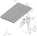
- FIG. 4 is an enlarged perspective view of the bottom plate and the outer side wall in FIG. 2
- FIG. 5 is a top view of FIG. 4
- FIG. 6 is a partial enlarged perspective view of the side frame in FIG. 2 .
- the fixing portion 400 may be disposed at the location at which the cell array structure 100 and the pack case 200 face each other.
- the fixing portion 400 may include a protruding structure in any one of the cell array structure 100 or the pack case 200, and a recessed structure in the other one of the cell array structure 100 or the pack case 200. Additionally, the protruding structure and the recessed structure may form-fit to each other.
- the fixing portion 400 may include a fastening protrusion portion 410 in any one of the cell array structure 100 or the outer side wall 220, and a fastening groove portion 420 in the other one of the cell array structure 100 or the outer side wall 220.
- the fastening protrusion portion 410 may be disposed at the inner wall of the outer side wall 220.
- the fastening protrusion portion 410 may be disposed in the middle of the inner wall of the outer side wall 220.
- the fastening protrusion portion 410 may form-fit to the fastening groove portion 420 and configured to mount a part of the fastening groove portion 420.
- the fastening groove portion 420 may be disposed at the cell array structure 100.
- the fastening groove portion 420 may be formed at a side wall 132 on the outermost side of the cell array structure 100 and may be disposed opposite the fastening protrusion portion 410.
- the fastening groove portion 420 may be formed in a so-called empty space that is not interfered with a location at which any one battery cell 112 and its adjacent other battery cell 112 are arranged side by side in the cell array structure 100.
- the protruding structure (the fastening protrusion portion 410 in this embodiment) on the inner wall of the outer side wall 220 and the recessed structure (the fastening groove portion 420 in this embodiment) in the empty space between the battery cells 112 may form-fit to each other.
- the protruding structure on the inner wall of the pack case 200 and the recessed structure in the empty space between the battery cells 112 form-fit to each other, it may be possible to optimize the mounting structure for mounting the cell array structure 100 in the pack case 200, thereby increasing energy density of the battery pack 10. This may eliminate the need for a mounting structure (a flange, etc.) on the pack case 200 to fix the cell array structure, and more battery cells 112 may be received as much as the space occupied by the deleted mounting structure. Alternatively, it may be possible to increase the capacity of the battery cell 112 for the same volume of the battery pack 10.
- the pack case 200 and the cell array structure 100 may be strongly coupled to each other.
- the cell array structure 100 may be fixed to the pack case 200 more firmly.
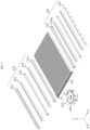
- FIG. 7 is a diagram of the cell array structure applied to the battery pack according to an embodiment of the present disclosure
- FIG. 8 is an assembly perspective view of FIG. 7
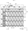
- FIG. 9 is a partial top view of the cell array structure received in the battery pack according to an embodiment of the present disclosure.
- the cell array structure 100 may include a plurality of unit cell groups 110 including the plurality of battery cells 112 and a cooling tube 115 attached to the plurality of battery cells 112, and the side frame 130 disposed between the plurality of unit cell groups 110.
- the battery cell 112 may have a tab portion 113 and an upper surface 114 on top.
- the tab portion 113 may have a first polarity
- the upper surface 114 may have a second polarity.
- the tab portion 113 and the upper surface 114 may be electrically isolated from each other.
- the first polarity may be a positive polarity of the battery cell 112, and the second polarity may be a negative electrode of the battery cell 112. That is, the tab portion 113 may be a positive electrode portion of the battery cell 112, and the upper surface 114 may be a negative electrode portion of the battery cell 112.
- the tab portion 113 may be extended from the upper surface 114. Alternatively, the tab portion 113 may not be extended from the upper surface 114.
- the tab portion 113 may be disposed on the same plane as the upper surface, like a so-called tab-less structure.
- the components of the battery cell 112 are well known to those skilled in the art at the time of filing the application, and its detailed description is omitted.
- a plurality of battery cells 112 may form a cell array 111. That is, the cell array 111 may include the plurality of battery cells 112 arranged in a line side by side along the length direction (X axis direction) of the battery pack 10. The number of battery cells 112 that form the cell array 111 is not limited to a particular range.
- the unit cell group 110 may include a pair of cell arrays 111 and the cooling tube 115 between the pair of cell arrays 111. That is, the unit cell group 110 may include the pair (two) of cell arrays 111 and the cooling tube 115 interposed between the pair of cell arrays 111.
- the cooling tube 115 cools the battery cell 112 while being in contact with one surface of the cell array 111.
- the cooling tube 115 may be a structure having an empty space in which a cooling medium flows, and may be configured to directly transfer heat from the battery cells 112 to the cooling medium while being in contact the outer surface of the plurality of battery cells 112.
- the fastening groove portion 420 may include an inward recessed groove 421 on one surface of the side wall 132 along the thickness direction of the side wall 132, and a mounting step 425 protruding in the inward recessed groove 421.
Landscapes
- Chemical & Material Sciences (AREA)
- General Chemical & Material Sciences (AREA)
- Electrochemistry (AREA)
- Chemical Kinetics & Catalysis (AREA)
- Engineering & Computer Science (AREA)
- Aviation & Aerospace Engineering (AREA)
- Sustainable Energy (AREA)
- Mechanical Engineering (AREA)
- Transportation (AREA)
- Power Engineering (AREA)
- Life Sciences & Earth Sciences (AREA)
- Sustainable Development (AREA)
- Battery Mounting, Suspending (AREA)
Abstract
Description
- The present disclosure relates to a battery pack and a vehicle including the same, and more particularly, to a battery pack in which a cell array structure is mounted in a pack case using an empty space between battery cells to increase energy density of the battery pack and a vehicle including the same. This application is based on and claims priority from
Korean Patent Application No. 10-2023-0123394, filed on September 15, 2023 - Due to being easily applicable to different types of products and having electrical properties such as high energy density, secondary batteries are commonly used in not only portable devices but also electric vehicles (EVs) or hybrid electric vehicles (HEVs) that are powered by an electric power source. Secondary batteries can remarkably reduce the use of fossil fuels. In addition to the primary advantage, another advantage is that they do not generate by-products from the use of energy. Due to these advantages, secondary batteries are gaining attention as a new eco-friendly and energy efficient source of energy.
- The types of secondary batteries widely used at present include lithium ion batteries, lithium polymer batteries, nickel cadmium batteries, nickel hydrogen batteries, nickel zinc batteries and so on. A unit secondary battery cell or a unit battery cell has an operating voltage of about 2.5V to 4.5V. Accordingly, when higher output voltage is required, a plurality of battery cells may be connected in series to form a battery pack. Additionally, the battery pack may be formed by connecting the plurality of battery cells in parallel according to the charge/discharge capacity required for the battery pack. Accordingly, the number of battery cells included in the battery pack and the electrical connection type may be variously set depending on the required output voltage and/or charge/discharge capacity.
- Meanwhile, lithium ion secondary batteries may be classified into pouch-type secondary batteries in which the electrode assembly is included in a pouch of an aluminum laminate sheet and can-type secondary batteries in which the electrode assembly is included in a metal can according to the shape of the battery case. Additionally, the can-type secondary batteries may be sub-classified into cylindrical batteries and prismatic batteries according to the shape of the metal can.
- In particular, to provide high voltage and high current, the cylindrical batteries form a battery module or a battery pack by piling or stacking the plurality of battery cells with or without a cartridge to form at least one unit structure (for example, a cell to pack structure), establishing electrical connection and packaging in a pack case.
- Recently, in keeping up with the trend towards higher density of the pack, the unit structure including the plurality of battery cells tends to increase the size and weight. Accordingly, it is necessary to improve a mounting structure for firmly coupling the unit structure to the pack case. In particular, in terms of energy density (E/D), it is necessary to optimize the mounting structure and shape to maximize the cell capacity for the same volume and improve assembly efficiency.
- The present disclosure is designed to solve the above-described problems, and therefore the present disclosure is directed to providing a battery pack in which a protruding structure on an inner wall of a pack case and a recessed structure in an empty space between battery cells form-fit to each other, thereby optimizing a mounting structure for mounting a cell array structure in a pack case and accordingly increasing energy density of the battery pack.
- The technical problems of the present disclosure to be solved are not limited to the aforementioned problems, and these and other problems will be clearly understood by those skilled in the art from the following description.
- A battery pack according to the present disclosure may include a cell array structure including a plurality of battery cells; a pack case accommodating the cell array structure; and a fixing portion disposed at a location at which the cell array structure and the pack case face each other and configured to fix the cell array structure to the pack case through form-fitting coupling.
- The fixing portion may include a protruding structure in any one of the cell array structure or the pack case and a recessed structure in the other one of the cell array structure or the pack case, and the protruding structure and the recessed structure may form-fit to each other.
- The pack case may include a bottom plate disposed below the cell array structure; and an outer side wall disposed at an outer edge of the bottom plate, and the fixing portion may be disposed on an outermost side of the cell array structure and an inner wall of the outer side wall.
- The fixing portion may include a fastening protrusion portion in any one of the cell array structure or the outer side wall; and a fastening groove portion in the other one of the cell array structure or the outer side wall.
- The cell array structure may include a plurality of unit cell groups including the plurality of battery cells; and a side frame disposed between the plurality of unit cell groups, the side frame may include a side structure interposed between the unit cell groups; and a side wall interposed between the pack case and the unit cell group, the fastening protrusion portion may be disposed in the outer side wall, and the fastening groove portion may be disposed in the side wall.
- The fastening groove portion may include an inward recessed groove formed on one surface of the side wall along a thickness direction of the side wall; and a mounting step protruding in the inward recessed groove.
- When the cell array structure is coupled to the pack case, the fastening protrusion portion may be mounted and supported on the mounting step.
- A horizontal cross section of the fastening protrusion portion may protrude in a triangular shape.
- The inward recessed groove may be recessed in a triangular shape to conform to a shape of the fastening protrusion portion.
- The inward recessed groove may be formed at an area that is not interfered with a location at which any one battery cell and an adjacent other battery cell are arranged side by side when the cell array structure is viewed from top.
- As the fastening protrusion portion is inserted into the fastening groove portion, the cell array structure may slidably move down and be mounted and supported on the pack case.
- The fastening protrusion portion and the mounting step may have a fastening hole in a longitudinal direction, and a fastening member may be coupled to the fastening hole.
- Additionally, according to the present disclosure, there is provided a vehicle including the above-described battery pack.
- According to an aspect of the present disclosure, as the protruding structure on the inner wall of the pack case and the recessed structure in the empty space between the battery cells form-fit to each other, it may be possible to optimize the mounting structure for mounting the cell array structure in the pack case and thereby increase energy density of the battery pack.
- Additionally, according to an aspect of the present disclosure, it may be possible to ensure a strong coupling strength between the pack case and the cell array structure, thereby firmly fixing the cell array structure to the pack case in keeping up with the trend of the cell array structure towards larger area and higher weight.
- Additionally, according to an aspect of the present disclosure, as the mounting and coupling operation may be performed by slidable coupling between the recessed structure of the cell array structure and the protruding structure of the pack case, it may be possible to improve assembly efficiency of the pack.
- The effects of the present disclosure are not limited to the aforementioned effects, and these and other effects will be clearly understood by those skilled in the art from the present disclosure and the accompanying drawings.
- The accompanying drawings illustrate exemplary embodiments of the present disclosure and together with the following detailed description, serve to provide a better understanding of the technical aspect of the present disclosure, and thus, the present disclosure should not be construed as being limited to the drawings.
-
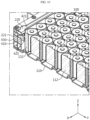
FIG. 1 is a schematic perspective view of the main components of a battery pack according to an embodiment of the present disclosure. -
FIG. 2 is an exploded perspective view ofFIG. 1 . -
FIG. 3 is a perspective view of a battery pack according to an embodiment of the present disclosure, from which a top cover plate is removed. -
FIG. 4 is an enlarged perspective view of a pack case inFIG. 2 . -
FIG. 5 is a top view ofFIG. 4 . -
FIG. 6 is a partial enlarged perspective view of a side frame inFIG. 2 . -
FIG. 7 is a diagram of a cell array structure applied to a battery pack according to an embodiment of the present disclosure. -
FIG. 8 is an assembly perspective view ofFIG. 7 . -
FIG. 9 is a partial top view of a cell array structure received in a battery pack according to an embodiment of the present disclosure. -
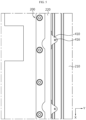
FIG. 10 is a cutaway perspective view ofFIG. 9 , taken along the line A-A'. -
FIG. 11 is a longitudinal cross-sectional view of a battery pack according to an embodiment of the present disclosure. -
FIG. 12 is a diagram illustrating a vehicle according to an embodiment of the present disclosure. - Hereinafter, exemplary embodiments of the present disclosure will be described in detail with reference to the accompanying drawings. Prior to the description, it should be understood that the terms or words used in the specification and the appended claims should not be construed as limited to general and dictionary meanings, but rather interpreted based on the meanings and concepts corresponding to the technical aspect of the present disclosure on the basis of the principle that the inventor is allowed to define terms appropriately for the best explanation.
- Therefore, the description provided herein and illustrations in the drawings are provided to describe some exemplary embodiments of the present disclosure, but not intended to fully describe the technical aspect of the present disclosure, so it should be understood that a variety of other equivalents and modifications could have been made thereto at the time of filing the patent application.
- In the drawings, the size of each element or a particular part of the element is exaggerated, omitted or schematically shown for convenience and clarity of description. Accordingly, the size of each element does not exactly reflect the actual size. When it is determined that a detailed description of related known functions or elements may unnecessarily obscure the subject matter of the present disclosure, the description is omitted.
-
FIG. 1 is a schematic perspective view of the main components of a battery pack according to an embodiment of the present disclosure,FIG. 2 is an exploded perspective view ofFIG. 1 , andFIG. 3 is a perspective view of the battery pack according to an embodiment of the present disclosure, from which a top cover plate is removed. - Referring to
FIGs. 1 to 3 , thebattery pack 10 according to an embodiment of the present disclosure may include acell array structure 100 including a plurality ofbattery cells 112, apack case 200 accommodating thecell array structure 100, abusbar assembly 300 disposed on thecell array structure 100, thetop cover plate 230, and afixing portion 400 disposed at a location at which thecell array structure 100 and thepack case 200 face each other. - Referring primarily to
FIG. 2 , thecell array structure 100 may include the plurality ofbattery cells 112. - The plurality of
battery cells 112 may include secondary batteries, for example, cylindrical secondary batteries, pouch-type secondary batteries or prismatic secondary batteries. Hereinafter, this embodiment will be described based on cylindrical secondary batteries as the plurality ofbattery cells 112. Thebattery cells 112 may be a plurality of cylindrical secondary batteries arranged in the horizontal direction and standing in the vertical direction. - The plurality of
battery cells 112 standing upright may be stacked in the horizontal direction or on the horizontal plane (X-Y plane) as shown inFIG. 2 . Additionally, a cooling structure or a structure (aside frame 130 as described below) for maintaining the interval between thebattery cells 112 may be disposed or coupled between each of the plurality ofbattery cells 112 to form thecell array structure 100 which is an assembly ofbattery cells 112. - Here, the
cell array structure 100 may be a single assembly (structure) of flat plate type having a predetermined thickness (for example, the height of the battery cell 112) as described in detail below. Additionally, thecell array structure 100 may increase in area and thecell array structure 100 may increase in weight. The single large-area structure may have a predetermined structure strength. Accordingly, thecell array structure 100 may be a component of cell to pack. - The
pack case 200 may accommodate thecell array structure 100. As shown inFIGs. 2 and3 , thepack case 200 may include abottom plate 210, anouter side wall 220 disposed at the edge of thebottom plate 210, thebusbar assembly 300 disposed on thecell array structure 100 and thetop cover plate 230. Here, thecell array structure 100 may be received in the internal space formed by thebottom plate 210, theouter side wall 220 and thetop cover plate 230. - The
bottom plate 210 may be disposed below thecell array structure 100. Thebottom plate 210 may contact and support the bottom of thecell array structure 100. Thebottom plate 210 may include aconvex portion 211 and aconcave portion 212. - The
outer side wall 220 refers to a sort of frame having a predetermined height disposed at the outer edge, and thebottom plate 210 may be coupled to the bottom of theouter side wall 220. Theouter side wall 220 may be hollow and may have a plurality of reinforcement partitions 221 (seeFIGs. 10 ,11 ). - The
busbar assembly 300 may be disposed on thecell array structure 100 and configured to electrically the plurality ofbattery cells 112. Additionally, thetop cover plate 230 may be disposed on top of thepack case 200 and configured to cover the upper surface of thecell array structure 100. -
FIG. 4 is an enlarged perspective view of the bottom plate and the outer side wall inFIG. 2 ,FIG. 5 is a top view ofFIG. 4 , andFIG. 6 is a partial enlarged perspective view of the side frame inFIG. 2 . - Referring to
FIGs. 4 to 6 together withFIG. 2 , the fixingportion 400 may be disposed at the location at which thecell array structure 100 and thepack case 200 face each other. The fixingportion 400 may include a protruding structure in any one of thecell array structure 100 or thepack case 200, and a recessed structure in the other one of thecell array structure 100 or thepack case 200. Additionally, the protruding structure and the recessed structure may form-fit to each other. - The fixing
portion 400 may include afastening protrusion portion 410 in any one of thecell array structure 100 or theouter side wall 220, and afastening groove portion 420 in the other one of thecell array structure 100 or theouter side wall 220. - For example, the
fastening protrusion portion 410 may be disposed at the inner wall of theouter side wall 220. Thefastening protrusion portion 410 may be disposed in the middle of the inner wall of theouter side wall 220. Thefastening protrusion portion 410 may form-fit to thefastening groove portion 420 and configured to mount a part of thefastening groove portion 420. - Additionally, the
fastening groove portion 420 may be disposed at thecell array structure 100. Thefastening groove portion 420 may be formed at aside wall 132 on the outermost side of thecell array structure 100 and may be disposed opposite thefastening protrusion portion 410. In particular, thefastening groove portion 420 may be formed in a so-called empty space that is not interfered with a location at which any onebattery cell 112 and its adjacentother battery cell 112 are arranged side by side in thecell array structure 100. - Accordingly, when the
cell array structure 100 is assembled with thepack case 200, the protruding structure (thefastening protrusion portion 410 in this embodiment) on the inner wall of theouter side wall 220 and the recessed structure (thefastening groove portion 420 in this embodiment) in the empty space between thebattery cells 112 may form-fit to each other. - According to this embodiment, as the protruding structure on the inner wall of the
pack case 200 and the recessed structure in the empty space between thebattery cells 112 form-fit to each other, it may be possible to optimize the mounting structure for mounting thecell array structure 100 in thepack case 200, thereby increasing energy density of thebattery pack 10. This may eliminate the need for a mounting structure (a flange, etc.) on thepack case 200 to fix the cell array structure, andmore battery cells 112 may be received as much as the space occupied by the deleted mounting structure. Alternatively, it may be possible to increase the capacity of thebattery cell 112 for the same volume of thebattery pack 10. - Additionally, when the
fastening groove portion 420 is inserted into thefastening protrusion portion 410 and a part of thefastening groove portion 420 is mounted and supported on thefastening protrusion portion 410, thepack case 200 and thecell array structure 100 may be strongly coupled to each other. In keeping up with the trend of thecell array structure 100 towards larger area and higher weight, thecell array structure 100 may be fixed to thepack case 200 more firmly. - Hereinafter, the
cell array structure 100 and the fixingportion 400 according to an embodiment of the present disclosure will be described in more detail. -
FIG. 7 is a diagram of the cell array structure applied to the battery pack according to an embodiment of the present disclosure,FIG. 8 is an assembly perspective view ofFIG. 7 , andFIG. 9 is a partial top view of the cell array structure received in the battery pack according to an embodiment of the present disclosure. - Referring to
FIGs. 7 to 9 together withFIG. 2 , thecell array structure 100 may include a plurality ofunit cell groups 110 including the plurality ofbattery cells 112 and acooling tube 115 attached to the plurality ofbattery cells 112, and theside frame 130 disposed between the plurality ofunit cell groups 110. - The
battery cell 112 may have atab portion 113 and anupper surface 114 on top. Thetab portion 113 may have a first polarity, and theupper surface 114 may have a second polarity. Thetab portion 113 and theupper surface 114 may be electrically isolated from each other. The first polarity may be a positive polarity of thebattery cell 112, and the second polarity may be a negative electrode of thebattery cell 112. That is, thetab portion 113 may be a positive electrode portion of thebattery cell 112, and theupper surface 114 may be a negative electrode portion of thebattery cell 112. Thetab portion 113 may be extended from theupper surface 114. Alternatively, thetab portion 113 may not be extended from theupper surface 114. For example, thetab portion 113 may be disposed on the same plane as the upper surface, like a so-called tab-less structure. The components of thebattery cell 112 are well known to those skilled in the art at the time of filing the application, and its detailed description is omitted. - A plurality of
battery cells 112 may form acell array 111. That is, thecell array 111 may include the plurality ofbattery cells 112 arranged in a line side by side along the length direction (X axis direction) of thebattery pack 10. The number ofbattery cells 112 that form thecell array 111 is not limited to a particular range. - Additionally, the
unit cell group 110 may include a pair ofcell arrays 111 and thecooling tube 115 between the pair ofcell arrays 111. That is, theunit cell group 110 may include the pair (two) ofcell arrays 111 and thecooling tube 115 interposed between the pair ofcell arrays 111. Here, the coolingtube 115 cools thebattery cell 112 while being in contact with one surface of thecell array 111. The coolingtube 115 may be a structure having an empty space in which a cooling medium flows, and may be configured to directly transfer heat from thebattery cells 112 to the cooling medium while being in contact the outer surface of the plurality ofbattery cells 112. - Because the plurality of
battery cells 112 is disposed on the outer side, theunit cell group 110 has a curved shape. Accordingly, thecell array structure 100 may include theside frame 130 to accommodate the curved shape and to fix the plurality ofbattery cells 112 and maintain the interval between thebattery cells 112. - The
side frame 130 may be disposed between theunit cell group 110 and the adjacentunit cell group 110, or at the front end of theunit cell group 110. Specifically, theside frame 130 may include aside structure 131 interposed between theunit cell groups 110, and theside wall 132 interposed between thepack case 200 and theunit cell group 110. - The
side structure 131 may be disposed between the pair ofunit cell groups 110. Theside structure 131 may be disposed between theunit cell group 110 and the adjacentunit cell group 110 to fix at least one pair ofunit cell groups 110 and maintain the interval between thebattery cells 112. As primarily shown inFIGs. 2 and3 , theside structure 131 may have aconcave groove 131a to conform to the shape of the outer surface of theunit cell group 110 on each of one surface and the other surface in the length direction. The internal curvature of theconcave groove 131a or the number ofconcave grooves 131a may be determined according to the specification of the outer surface of theunit cell group 110 or thebattery cell 112 form-fitted to theside structure 131. - A pair of
side walls 132 may be disposed at two sides in the assembly direction (Y axis direction) in which theunit cell group 110 and theside structure 131 are assembled. Theside wall 132 may be disposed at the outermost side of thecell array structure 100 in the width direction (X axis direction). One surface of theside wall 132 may have theconcave recess 133 in which one surface of theunit cell group 110 is received, and the other surface (the opposite surface) may be so flat to contact theouter side wall 220 of thepack case 200. Accordingly, thecell array structure 100 and theouter side wall 220 may contact each other without an unnecessary gap. - As described above, the plurality of
unit cell groups 110, the plurality ofside structures 131 and the plurality ofside walls 132 may be assembled to form onecell array structure 100. Thecell array structure 100 may be a structure having structure strength without any module case. - Specifically, the
side frame 130 may be disposed for each of the plurality ofbattery cells 112 in thecell array structure 100, or on one surface of thecell array 111 and configured to fix and support the plurality ofbattery cells 112. Additionally, theside frame 130 may be attached to the plurality ofbattery cells 112 to form a structure as thecell array structure 100, thereby achieving larger area and higher weight. - Referring to
FIG. 8 together withFIGs. 4 to 6 , the fixingportion 400 may include thefastening protrusion portion 410 in any oneouter side walls 220, and thefastening groove portion 420 in thecell array structure 100. - The
fastening protrusion portion 410 may be disposed on the inner wall of theouter side wall 220, and may be disposed at the central part of theouter side wall 220 in the thickness direction. Additionally, the horizontal cross section of thefastening protrusion portion 410 may protrude in a triangular shape. Thefastening protrusion portion 410 may have afastening hole 416 in the longitudinal direction, and afastening member 430 may be coupled to thefastening hole 416. - The
fastening groove portion 420 may include an inward recessedgroove 421 on one surface of theside wall 132 along the thickness direction of theside wall 132, and a mountingstep 425 protruding in the inward recessedgroove 421. - The inward recessed
groove 421 may be recessed in a triangular shape to conform to the shape of thefastening protrusion portion 410. That is, the inward recessedgroove 421 may be recessed in the shape of a triangle with the top vertex facing the thickness direction of theside wall 132. Additionally, the inward recessedgroove 421 may be continuously formed from top to bottom of theside wall 132 in the thickness direction of theside wall 132. - The inward recessed
groove 421 may be formed at the area that is not interfered with the location at which any onebattery cell 112 and its adjacentother battery cell 112 are arranged side by side when thecell array structure 100 is viewed from the top. That is, the inward recessedgroove 421 may be formed in the empty space that is an unused space (a buffer space) between thebattery cell 112 and theadjacent battery cell 112. Accordingly, compared to the conventional structure having an additional mounting space, this may have a beneficial effect on energy density. - The mounting
step 425 may be disposed in the middle of the inward recessedgroove 421. The mountingstep 425 may protrude outward from the triangular recessed structure of the inward recessedgroove 421. The mountingstep 425 may be mounted on the upper surface of thefastening protrusion portion 410 and configured to mount and support thecell array structure 100 on thepack case 200. The mountingstep 425 may have afastening hole 426 in the longitudinal direction. - According to this embodiment, as the protruding structure on the inner wall of the
outer side wall 220 and the recessed structure in the empty space between thebattery cells 112 form-fit to each other, it may be possible to optimize the mounting structure for mounting thecell array structure 100 in thepack case 200, thereby increasing energy density of thebattery pack 10. - Additionally, according to this embodiment, it may be possible to ensure a strong coupling strength between the
pack case 200 and thecell array structure 100, thereby firmly fixing thecell array structure 100 to thepack case 200 in keeping up with the trend of thecell array structure 100 towards larger area and higher weight. As the fixingportion 400 may firmly support thecell array structure 100 of larger area, it may be possible to ensure high resistance to vibration or external impact. - Additionally, as the mounting and coupling may be performed by slidable coupling between the recessed structure of the
cell array structure 100 and the protruding structure of thepack case 200, it may be possible to improve assembly efficiency of the pack. - Furthermore, as the
cell array structure 100 is firmly fixed to thepack case 200, it may be possible to significantly reduce the disconnect or short issue of the electrical connection line that may occur in the event of deformation such as twist of thecell array structure 100 itself or twist or dislocation due to external impact and reduce the crack or damage risk at the mounting location of thecell array structure 100 and thepack case 200. - Hereinafter, the coupling process will be described.
-
FIG. 10 is a cutaway perspective view ofFIG. 9 , taken along the line A-A', andFIG. 11 is a longitudinal cross-sectional view of the battery pack according to an embodiment of the present disclosure. - The
pack case 200 is placed, and thecell array structure 100 moves down from above. - As the
fastening protrusion portion 410 is inserted into thefastening groove portion 420, thecell array structure 100 slidably moves down. - The mounting
step 425 may protrude outward from a location of the inward recessedgroove 421. Accordingly, as thecell array structure 100 slidably moves down, when thecell array structure 100 is coupled to thepack case 200, the mountingstep 425 is mounted on thefastening protrusion portion 410. - As shown in
FIGs. 10 and11 , thefastening protrusion portion 410 and the mountingstep 425 has the fastening holes 416, 426 in the longitudinal direction, respectively, and thefastening member 430 is coupled to the fastening holes 416, 426. - Accordingly, as the protruding structure on the inner wall of the
outer side wall 220 and the recessed structure in the empty space between thebattery cells 112 form-fit to each other, it may be possible to optimize the mounting structure for mounting thecell array structure 100 in thepack case 200, thereby increasing energy density of thebattery pack 10. - Additionally, according to this embodiment, it may be possible to ensure a strong coupling strength between the
pack case 200 and thecell array structure 100, thereby firmly fixing thecell array structure 100 to thepack case 200 in keeping up with the trend of thecell array structure 100 towards larger area and higher weight. As the fixingportion 400 may firmly support thecell array structure 100 of larger area, it may be possible to ensure resistance to vibration or external impact. - Additionally, as the mounting and coupling operation may be performed by slidable coupling between the recessed structure of the
cell array structure 100 and the protruding structure of thepack case 200, it may be possible to improve assembly efficiency of the pack. - Although not shown, the
battery pack 10 according to the present disclosure may further include various types of devices to control the charge and discharge of thebattery cells 112, for example, a Battery Management System (BMS), a current sensor, a fuse, etc. -
FIG. 12 is a diagram illustrating a vehicle according to an embodiment of the present disclosure. - Referring to
FIG. 12 , thebattery pack 10 according to the present disclosure may be applied to the vehicle V such as an electric vehicle or a hybrid electric vehicle. That is, the vehicle V according to the present disclosure may include thebattery pack 10 according to the present disclosure. Thebattery pack 10 may be installed at a car frame below the vehicle seat or a trunk space, and when installing in the vehicle, thebattery pack 10 may be placed in the reverse order, if necessary. - The terms indicating directions such as upper, lower, left, right, front and rear are used for convenience of description, but it is obvious to those skilled in the art that the terms may change depending on the position of the stated element or an observer.
- Although the present disclosure has been hereinabove described by a limited number of embodiments and drawings, the present disclosure is not limited thereto, and it is obvious to those skilled in the art that a variety of changes and modifications may be made thereto within the technical aspect of the present disclosure and the appended claims and equivalents thereof.
[List of reference numerals] 100: Cell array structure 110: Unit cell group 111: Cell array 112: Battery cell 115: Cooling tube 130: Side frame 131: Side structure 132: Side wall 200: Pack case 210: Bottom plate 220: Outer side wall 221: Reinforcement partition 230: Top cover plate 300: Busbar assembly 400: Fixing portion 410: Fastening protrusion portion 416: Fastening hole 420: Fastening groove portion 421: Inward recessed groove 425: Mounting step 426: Fastening hole 430: Fastening member
Claims (13)
- A battery pack comprising:a cell array structure including a plurality of battery cells;a pack case accommodating the cell array structure; anda fixing portion disposed at a location at which the cell array structure and the pack case face each other and configured to fix the cell array structure to the pack case through form-fitting coupling.
- The battery pack according to claim 1, wherein the fixing portion includes a protruding structure in any one of the cell array structure or the pack case and a recessed structure in the other one of the cell array structure or the pack case, and the protruding structure and the recessed structure form-fit to each other.
- The battery pack according to claim 1, wherein the pack case includes:a bottom plate disposed below the cell array structure; andan outer side wall disposed at an outer edge of the bottom plate, andwherein the fixing portion is disposed on an outermost side of the cell array structure and an inner wall of the outer side wall.
- The battery pack according to claim 3, wherein the fixing portion includes:a fastening protrusion portion in any one of the cell array structure or the outer side wall; anda fastening groove portion in the other one of the cell array structure or the outer side wall.
- The battery pack according to claim 4, wherein the cell array structure includes:a plurality of unit cell groups including the plurality of battery cells; anda side frame disposed between the plurality of unit cell groups,wherein the side frame includes:a side structure interposed between the unit cell groups; anda side wall interposed between the pack case and the unit cell group,wherein the fastening protrusion portion is disposed in the outer side wall, andwherein the fastening groove portion is disposed in the side wall.
- The battery pack according to claim 5, wherein the fastening groove portion includes:an inward recessed groove formed on one surface of the side wall along a thickness direction of the side wall; anda mounting step protruding in the inward recessed groove.
- The battery pack according to claim 6, wherein when the cell array structure is coupled to the pack case, the fastening protrusion portion is mounted and supported on the mounting step.
- The battery pack according to claim 4, wherein a horizontal cross section of the fastening protrusion portion protrudes in a triangular shape.
- The battery pack according to claim 6, wherein the inward recessed groove is recessed in a triangular shape to conform to a shape of the fastening protrusion portion.
- The battery pack according to claim 6, wherein the inward recessed groove is formed at an area that is not interfered with a location at which any one battery cell and an adjacent other battery cell are arranged side by side when the cell array structure is viewed from top.
- The battery pack according to claim 6, wherein as the fastening protrusion portion is inserted into the fastening groove portion, the cell array structure slidably moves down and is mounted and supported on the pack case.
- The battery pack according to claim 6, wherein the fastening protrusion portion and the mounting step have a fastening hole in a longitudinal direction, and
wherein a fastening member is coupled to the fastening hole. - A vehicle comprising the battery pack according to any one of claims 1 to 12.
Applications Claiming Priority (2)
| Application Number | Priority Date | Filing Date | Title |
|---|---|---|---|
| KR1020230123394A KR20250040390A (en) | 2023-09-15 | 2023-09-15 | Battery pack and vehicle including the same |
| PCT/KR2024/008992 WO2025058190A1 (en) | 2023-09-15 | 2024-06-27 | Battery pack and vehicle including same |
Publications (2)
| Publication Number | Publication Date |
|---|---|
| EP4576366A1 true EP4576366A1 (en) | 2025-06-25 |
| EP4576366A4 EP4576366A4 (en) | 2026-01-14 |
Family
ID=95022295
Family Applications (1)
| Application Number | Title | Priority Date | Filing Date |
|---|---|---|---|
| EP24863840.5A Pending EP4576366A4 (en) | 2023-09-15 | 2024-06-27 | BATTERY PACK AND VEHICLE WITH IT |
Country Status (6)
| Country | Link |
|---|---|
| EP (1) | EP4576366A4 (en) |
| JP (1) | JP2026512266A (en) |
| KR (1) | KR20250040390A (en) |
| CN (1) | CN120476508A (en) |
| TW (1) | TW202520543A (en) |
| WO (1) | WO2025058190A1 (en) |
Family Cites Families (10)
| Publication number | Priority date | Publication date | Assignee | Title |
|---|---|---|---|---|
| KR100850849B1 (en) * | 2004-12-09 | 2008-08-06 | 주식회사 엘지화학 | Battery case for thermal control and battery pack structure using the same |
| US8134343B2 (en) * | 2007-04-27 | 2012-03-13 | Flextronics International Kft | Energy storage device for starting engines of motor vehicles and other transportation systems |
| JP5451211B2 (en) * | 2009-06-26 | 2014-03-26 | パナソニック株式会社 | Power storage unit |
| KR101359306B1 (en) * | 2011-06-27 | 2014-02-21 | 주식회사 엘지화학 | Battery Module Assembly and Battery Pack Comprising the Same |
| US9893342B2 (en) * | 2013-08-09 | 2018-02-13 | Hitachi Automotive Systems, Ltd. | Electricity storage module |
| KR102030901B1 (en) * | 2017-09-29 | 2019-10-10 | 보성파워텍 주식회사 | Battery cartridge |
| KR102660426B1 (en) * | 2018-11-07 | 2024-04-23 | 에스케이온 주식회사 | Battery Module |
| KR102828349B1 (en) * | 2019-09-09 | 2025-07-03 | 삼성에스디아이 주식회사 | Battery pack |
| KR102802106B1 (en) * | 2020-07-28 | 2025-05-02 | 에스케이온 주식회사 | Battery pack |
| KR20230123394A (en) | 2022-02-16 | 2023-08-23 | 박재성 | Waste heat air reuse device of laundry recovery dryer |
-
2023
- 2023-09-15 KR KR1020230123394A patent/KR20250040390A/en active Pending
-
2024
- 2024-06-27 JP JP2025554959A patent/JP2026512266A/en active Pending
- 2024-06-27 CN CN202480005546.8A patent/CN120476508A/en active Pending
- 2024-06-27 WO PCT/KR2024/008992 patent/WO2025058190A1/en active Pending
- 2024-06-27 EP EP24863840.5A patent/EP4576366A4/en active Pending
- 2024-09-04 TW TW113133535A patent/TW202520543A/en unknown
Also Published As
| Publication number | Publication date |
|---|---|
| WO2025058190A1 (en) | 2025-03-20 |
| CN120476508A (en) | 2025-08-12 |
| TW202520543A (en) | 2025-05-16 |
| EP4576366A4 (en) | 2026-01-14 |
| JP2026512266A (en) | 2026-04-15 |
| KR20250040390A (en) | 2025-03-24 |
Similar Documents
| Publication | Publication Date | Title |
|---|---|---|
| US20240222760A1 (en) | Cell, power battery pack, and electric vehicle | |
| US11264670B2 (en) | Battery pack having expandable battery module structure | |
| US11196120B2 (en) | Battery module, and battery pack and vehicle comprising same | |
| US20210313657A1 (en) | Battery Module with ICB Assembly in Space-Saving Structure | |
| EP4290661B1 (en) | Battery pack and vehicle including the same | |
| US20190157709A1 (en) | Cell pack and method for producing unit cell for use in cell pack | |
| EP4187702B1 (en) | Battery pack and vehicle comprising same | |
| EP3780287B1 (en) | Battery module including connector having shock absorbing structure | |
| KR102544785B1 (en) | Battery pack and vehicle comprising the battery pack | |
| EP4376190A1 (en) | Battery pack and vehicle including same | |
| EP4576366A1 (en) | Battery pack and vehicle including same | |
| EP4654354A1 (en) | Battery pack | |
| KR102900917B1 (en) | Battery pack and vehicle comprising the battery pack | |
| EP4708508A1 (en) | Battery pack and vehicle including same | |
| US20260011864A1 (en) | Battery module and battery pack | |
| EP4632901A1 (en) | Battery system with improved cell stack frame | |
| EP4421967A1 (en) | Battery module comprising upper/lower-separable bus bar frame, and method for assembling same | |
| EP4708459A1 (en) | Battery module and battery pack | |
| EP4557482A1 (en) | Battery pack and vehicle comprising same | |
| KR102165018B1 (en) | Battery module, battery pack comprising the battery module and vehicle comprising the battery pack | |
| KR20260063370A (en) | Battery pack and vehicle comprising the same | |
| KR20240012297A (en) | Battery pack and vehicle including the same | |
| CN121153161A (en) | Battery pack and vehicle including the battery pack | |
| WO2025193413A1 (en) | Battery tower design for heavy-duty electric powertrains | |
| CN118575345A (en) | Battery pack and vehicle including the same |
Legal Events
| Date | Code | Title | Description |
|---|---|---|---|
| STAA | Information on the status of an ep patent application or granted ep patent |
Free format text: STATUS: UNKNOWN |
|
| STAA | Information on the status of an ep patent application or granted ep patent |
Free format text: STATUS: THE INTERNATIONAL PUBLICATION HAS BEEN MADE |
|
| PUAI | Public reference made under article 153(3) epc to a published international application that has entered the european phase |
Free format text: ORIGINAL CODE: 0009012 |
|
| STAA | Information on the status of an ep patent application or granted ep patent |
Free format text: STATUS: REQUEST FOR EXAMINATION WAS MADE |
|
| 17P | Request for examination filed |
Effective date: 20250320 |
|
| AK | Designated contracting states |
Kind code of ref document: A1 Designated state(s): AL AT BE BG CH CY CZ DE DK EE ES FI FR GB GR HR HU IE IS IT LI LT LU LV MC ME MK MT NL NO PL PT RO RS SE SI SK SM TR |
|
| A4 | Supplementary search report drawn up and despatched |
Effective date: 20251217 |
|
| RIC1 | Information provided on ipc code assigned before grant |
Ipc: H01M 50/244 20210101AFI20251211BHEP Ipc: H01M 50/209 20210101ALI20251211BHEP Ipc: H01M 50/291 20210101ALI20251211BHEP Ipc: H01M 50/249 20210101ALI20251211BHEP Ipc: H01M 50/204 20210101ALI20251211BHEP Ipc: H01M 50/213 20210101ALI20251211BHEP Ipc: B60L 50/64 20190101ALI20251211BHEP Ipc: H01M 50/242 20210101ALI20251211BHEP Ipc: H01M 50/264 20210101ALI20251211BHEP |