EP4576362A1 - Battery module and battery pack including same - Google Patents
Battery module and battery pack including same Download PDFInfo
- Publication number
- EP4576362A1 EP4576362A1 EP23951598.4A EP23951598A EP4576362A1 EP 4576362 A1 EP4576362 A1 EP 4576362A1 EP 23951598 A EP23951598 A EP 23951598A EP 4576362 A1 EP4576362 A1 EP 4576362A1
- Authority
- EP
- European Patent Office
- Prior art keywords
- battery
- battery cells
- battery cell
- module
- cells
- Prior art date
- Legal status (The legal status is an assumption and is not a legal conclusion. Google has not performed a legal analysis and makes no representation as to the accuracy of the status listed.)
- Pending
Links
Images



Classifications
-
- H—ELECTRICITY
- H01—ELECTRIC ELEMENTS
- H01M—PROCESSES OR MEANS, e.g. BATTERIES, FOR THE DIRECT CONVERSION OF CHEMICAL ENERGY INTO ELECTRICAL ENERGY
- H01M50/00—Constructional details or processes of manufacture of the non-active parts of electrochemical cells other than fuel cells, e.g. hybrid cells
- H01M50/20—Mountings; Secondary casings or frames; Racks, modules or packs; Suspension devices; Shock absorbers; Transport or carrying devices; Holders
- H01M50/204—Racks, modules or packs for multiple batteries or multiple cells
- H01M50/207—Racks, modules or packs for multiple batteries or multiple cells characterised by their shape
- H01M50/211—Racks, modules or packs for multiple batteries or multiple cells characterised by their shape adapted for pouch cells
-
- H—ELECTRICITY
- H01—ELECTRIC ELEMENTS
- H01M—PROCESSES OR MEANS, e.g. BATTERIES, FOR THE DIRECT CONVERSION OF CHEMICAL ENERGY INTO ELECTRICAL ENERGY
- H01M10/00—Secondary cells; Manufacture thereof
- H01M10/04—Construction or manufacture in general
- H01M10/0468—Compression means for stacks of electrodes and separators
-
- H—ELECTRICITY
- H01—ELECTRIC ELEMENTS
- H01M—PROCESSES OR MEANS, e.g. BATTERIES, FOR THE DIRECT CONVERSION OF CHEMICAL ENERGY INTO ELECTRICAL ENERGY
- H01M10/00—Secondary cells; Manufacture thereof
- H01M10/04—Construction or manufacture in general
- H01M10/0481—Compression means other than compression means for stacks of electrodes and separators
-
- H—ELECTRICITY
- H01—ELECTRIC ELEMENTS
- H01M—PROCESSES OR MEANS, e.g. BATTERIES, FOR THE DIRECT CONVERSION OF CHEMICAL ENERGY INTO ELECTRICAL ENERGY
- H01M10/00—Secondary cells; Manufacture thereof
- H01M10/60—Heating or cooling; Temperature control
- H01M10/64—Heating or cooling; Temperature control characterised by the shape of the cells
- H01M10/647—Prismatic or flat cells, e.g. pouch cells
-
- H—ELECTRICITY
- H01—ELECTRIC ELEMENTS
- H01M—PROCESSES OR MEANS, e.g. BATTERIES, FOR THE DIRECT CONVERSION OF CHEMICAL ENERGY INTO ELECTRICAL ENERGY
- H01M50/00—Constructional details or processes of manufacture of the non-active parts of electrochemical cells other than fuel cells, e.g. hybrid cells
- H01M50/10—Primary casings; Jackets or wrappings
- H01M50/102—Primary casings; Jackets or wrappings characterised by their shape or physical structure
- H01M50/105—Pouches or flexible bags
-
- H—ELECTRICITY
- H01—ELECTRIC ELEMENTS
- H01M—PROCESSES OR MEANS, e.g. BATTERIES, FOR THE DIRECT CONVERSION OF CHEMICAL ENERGY INTO ELECTRICAL ENERGY
- H01M50/00—Constructional details or processes of manufacture of the non-active parts of electrochemical cells other than fuel cells, e.g. hybrid cells
- H01M50/20—Mountings; Secondary casings or frames; Racks, modules or packs; Suspension devices; Shock absorbers; Transport or carrying devices; Holders
- H01M50/204—Racks, modules or packs for multiple batteries or multiple cells
- H01M50/207—Racks, modules or packs for multiple batteries or multiple cells characterised by their shape
- H01M50/209—Racks, modules or packs for multiple batteries or multiple cells characterised by their shape adapted for prismatic or rectangular cells
-
- H—ELECTRICITY
- H01—ELECTRIC ELEMENTS
- H01M—PROCESSES OR MEANS, e.g. BATTERIES, FOR THE DIRECT CONVERSION OF CHEMICAL ENERGY INTO ELECTRICAL ENERGY
- H01M50/00—Constructional details or processes of manufacture of the non-active parts of electrochemical cells other than fuel cells, e.g. hybrid cells
- H01M50/20—Mountings; Secondary casings or frames; Racks, modules or packs; Suspension devices; Shock absorbers; Transport or carrying devices; Holders
- H01M50/218—Mountings; Secondary casings or frames; Racks, modules or packs; Suspension devices; Shock absorbers; Transport or carrying devices; Holders characterised by the material
- H01M50/22—Mountings; Secondary casings or frames; Racks, modules or packs; Suspension devices; Shock absorbers; Transport or carrying devices; Holders characterised by the material of the casings or racks
- H01M50/231—Mountings; Secondary casings or frames; Racks, modules or packs; Suspension devices; Shock absorbers; Transport or carrying devices; Holders characterised by the material of the casings or racks having a layered structure
-
- H—ELECTRICITY
- H01—ELECTRIC ELEMENTS
- H01M—PROCESSES OR MEANS, e.g. BATTERIES, FOR THE DIRECT CONVERSION OF CHEMICAL ENERGY INTO ELECTRICAL ENERGY
- H01M50/00—Constructional details or processes of manufacture of the non-active parts of electrochemical cells other than fuel cells, e.g. hybrid cells
- H01M50/20—Mountings; Secondary casings or frames; Racks, modules or packs; Suspension devices; Shock absorbers; Transport or carrying devices; Holders
- H01M50/233—Mountings; Secondary casings or frames; Racks, modules or packs; Suspension devices; Shock absorbers; Transport or carrying devices; Holders characterised by physical properties of casings or racks, e.g. dimensions
- H01M50/242—Mountings; Secondary casings or frames; Racks, modules or packs; Suspension devices; Shock absorbers; Transport or carrying devices; Holders characterised by physical properties of casings or racks, e.g. dimensions adapted for protecting batteries against vibrations, collision impact or swelling
-
- H—ELECTRICITY
- H01—ELECTRIC ELEMENTS
- H01M—PROCESSES OR MEANS, e.g. BATTERIES, FOR THE DIRECT CONVERSION OF CHEMICAL ENERGY INTO ELECTRICAL ENERGY
- H01M50/00—Constructional details or processes of manufacture of the non-active parts of electrochemical cells other than fuel cells, e.g. hybrid cells
- H01M50/20—Mountings; Secondary casings or frames; Racks, modules or packs; Suspension devices; Shock absorbers; Transport or carrying devices; Holders
- H01M50/289—Mountings; Secondary casings or frames; Racks, modules or packs; Suspension devices; Shock absorbers; Transport or carrying devices; Holders characterised by spacing elements or positioning means within frames, racks or packs
-
- H—ELECTRICITY
- H01—ELECTRIC ELEMENTS
- H01M—PROCESSES OR MEANS, e.g. BATTERIES, FOR THE DIRECT CONVERSION OF CHEMICAL ENERGY INTO ELECTRICAL ENERGY
- H01M50/00—Constructional details or processes of manufacture of the non-active parts of electrochemical cells other than fuel cells, e.g. hybrid cells
- H01M50/20—Mountings; Secondary casings or frames; Racks, modules or packs; Suspension devices; Shock absorbers; Transport or carrying devices; Holders
- H01M50/289—Mountings; Secondary casings or frames; Racks, modules or packs; Suspension devices; Shock absorbers; Transport or carrying devices; Holders characterised by spacing elements or positioning means within frames, racks or packs
- H01M50/291—Mountings; Secondary casings or frames; Racks, modules or packs; Suspension devices; Shock absorbers; Transport or carrying devices; Holders characterised by spacing elements or positioning means within frames, racks or packs characterised by their shape
-
- Y—GENERAL TAGGING OF NEW TECHNOLOGICAL DEVELOPMENTS; GENERAL TAGGING OF CROSS-SECTIONAL TECHNOLOGIES SPANNING OVER SEVERAL SECTIONS OF THE IPC; TECHNICAL SUBJECTS COVERED BY FORMER USPC CROSS-REFERENCE ART COLLECTIONS [XRACs] AND DIGESTS
- Y02—TECHNOLOGIES OR APPLICATIONS FOR MITIGATION OR ADAPTATION AGAINST CLIMATE CHANGE
- Y02E—REDUCTION OF GREENHOUSE GAS [GHG] EMISSIONS, RELATED TO ENERGY GENERATION, TRANSMISSION OR DISTRIBUTION
- Y02E60/00—Enabling technologies; Technologies with a potential or indirect contribution to GHG emissions mitigation
- Y02E60/10—Energy storage using batteries
Definitions
- the present disclosure relates to a battery module and a battery pack including the same, and more particularly, to a battery module with improved life performance and a battery pack including the same
- chargeable/dischargeable secondary batteries are used as a power source for an electric vehicle (EV), a hybrid electric vehicle (HEV), a plug-in hybrid electric vehicle (P-HEV) and the like, in an attempt to solve air pollution and the like caused by existing gasoline vehicles using fossil fuel. Therefore, the demand for development of the secondary battery is growing.
- EV electric vehicle
- HEV hybrid electric vehicle
- P-HEV plug-in hybrid electric vehicle
- the lithium secondary battery has come into the spotlight because it has advantages, for example, hardly exhibiting memory effects compared to nickel-based secondary batteries and thus being freely charged and discharged, and having very low self-discharge rate and high energy density.
- Such a lithium secondary battery mainly uses a lithium-based oxide and a carbonaceous material as a cathode active material and an anode active material, respectively.
- the lithium secondary battery includes an electrode assembly in which a cathode plate and an anode plate, each being coated with the cathode active material and the anode active material, are disposed with a separator being interposed between them, and an exterior material, i.e., a battery case, that seals and houses the electrode assembly together with the electrolyte.
- the lithium secondary battery may be classified into a can-type secondary battery in which the electrode assembly is mounted in a metal can, and a pouch-type secondary battery in which the electrode assembly is mounted in a pouch of an aluminum laminate sheet, depending on the shape of the exterior material.
- secondary batteries are widely used not only for small-sized devices such as portable electronic devices but also medium- and large-sized devices such as vehicles and energy storage systems.
- medium- and large-sized devices such as vehicles and energy storage systems.
- secondary batteries may be electrically connected to enhance capacity and output.
- a battery module in which a plurality of battery cells are electrically connected is used.
- a plurality of battery cells are connected to each other in series or parallel to form a cell assembly, thereby improving capacity and output.
- one or more battery modules can be mounted together with various control and protection systems such as a BMS (battery management system) and a cooling system to form a battery pack.
- BMS battery management system
- Capacity Retention after 800 cycles (Discharge Capacity for 800 Cycles/Discharge Capacity for 1 Cycle) ⁇ 100
- the reserved space ratio [%] per battery cell was calculated using the derived W, C, P and D values of Comparative Examples 1 to 3, and Examples 1 to 3 were calculated to have reserved space ratio values per battery cell of 1.93%, 1.88%, and 2.46%, respectively.
- the reserved space ratio per battery cell in Comparative Examples 1 to 3 is all the values of less than 3%.
- the capacity retention after 800 cycles, the capacity retention after 800 cycles in the battery module unit, and the difference in capacity degradation between battery cells and battery modules were calculated similarly to the method measured in Examples 1 to 4. Looking at the difference [%] in capacity degradation between battery cells and battery modules, Comparative Examples 1 to 3 were measured to be 18.8, 18.8, and 15.8, respectively.
- Fig. 6 is a perspective view showing a battery cell stack according to a comparative example of the present disclosure.
- a plurality of battery cells 11 are stacked to form a battery cell stack 12, and an adhesion part 60 may be provided at least at one place between the battery cells 11.
- This adhesion part 60 may be a double-sided tape, or an adhesion layer formed by applying an adhesive.
- the adhesion part 60 according to the present comparative example is not attached to the whole of one surface where the battery cells 11 face each other, but only to a portion thereof. In this case, the present inventors have confirmed that uneven pressure is applied to the battery cell 110 due to the partially formed adhesion part 60, and lithium plating (Li-Plating) occurs at both ends.
- the present inventors have analyzed the relationship between the lithium precipitation rate in Li-plating and the capacity retention of the battery cell, and confirmed that the lithium precipitation rate and the capacity retention of the battery cell have a strong negative correlation. That is, as the lithium precipitation rate increases, the capacity retention after 800 cycles decreases. Non-uniform surface pressure of the battery cell 110 resulting from the adhesion part 60 adversely affects the life performance of the battery module 100. Accordingly, the present inventors have proposed the following adhesion part 600 as a uniform pressure structure on the surface of the battery cell 110. Next, the formation area of the adhesion part 600 according to this embodiment will be described with reference to Figs. 3 , 7 and 8 .
- Fig. 7 is a perspective view showing a battery cell stack according to an embodiment of the present disclosure.
- Fig. 8 is a plan view showing a state where an adhesion part is formed on one surface of a battery cell according to an embodiment of the present disclosure.
- the battery cells 110 are sheet-shaped pouch-type battery cells, and may be stacked in an upright state so that one surface of the battery cells 110 is parallel to the side surface parts 210 and 220 (see Fig. 2 ).
- the battery cells 110 may be stacked so that the one surfaces of the battery cells face each other. That is, the one surface of the battery cells 110 described below corresponds to a portion of the battery cell 110 that is parallel to the side surface parts 210 and 220 of the module frame 200, and may face another battery cell 110, a compression pad 400, or side surface parts 210 and 220 of the module frame 200.
- the thermally conductive resin may include a thermally conductive adhesive material, and specifically, it may include at least one of silicone material, urethane material, and acrylic material.
- the thermally conductive resin may be in a liquid state during application or injection, and may be cured after application or injection to thereby serve to fix one or more battery cells 110 constituting the battery cell stack 120. In addition, it has excellent heat conduction characteristics, allowing heat generated in the battery cell 110 to be quickly transferred to the lower side of the battery module.
- the one or more battery modules according to embodiments of the present disclosure described above can be mounted together with various control and protection systems such as a BMS (battery management system), a BDU(battery disconnect unit), and a cooling system to form a battery pack.
- BMS battery management system
- BDU battery disconnect unit
- the battery pack can be applied to various devices.
- vehicle means such as an electric bike, an electric vehicle, and a hybrid electric vehicle, or an ESS (Energy Storage System) and may be applied to various devices capable of using a secondary battery, without being limited thereto.
- ESS Electronicgy Storage System
Landscapes
- Chemical & Material Sciences (AREA)
- Chemical Kinetics & Catalysis (AREA)
- Electrochemistry (AREA)
- General Chemical & Material Sciences (AREA)
- Engineering & Computer Science (AREA)
- Manufacturing & Machinery (AREA)
- Battery Mounting, Suspending (AREA)
Abstract
Description
- The present disclosure relates to a battery module and a battery pack including the same, and more particularly, to a battery module with improved life performance and a battery pack including the same
- In modern society, as portable devices such as a mobile phone, a notebook computer, a camcorder and a digital camera has been daily used, the development of technologies in the fields related to mobile devices as described above has been activated. In addition, chargeable/dischargeable secondary batteries are used as a power source for an electric vehicle (EV), a hybrid electric vehicle (HEV), a plug-in hybrid electric vehicle (P-HEV) and the like, in an attempt to solve air pollution and the like caused by existing gasoline vehicles using fossil fuel. Therefore, the demand for development of the secondary battery is growing.
- Currently commercialized secondary batteries include a nickel cadmium battery, a nickel hydrogen battery, a nickel zinc battery, and a lithium secondary battery. Among them, the lithium secondary battery has come into the spotlight because it has advantages, for example, hardly exhibiting memory effects compared to nickel-based secondary batteries and thus being freely charged and discharged, and having very low self-discharge rate and high energy density.
- Such a lithium secondary battery mainly uses a lithium-based oxide and a carbonaceous material as a cathode active material and an anode active material, respectively. The lithium secondary battery includes an electrode assembly in which a cathode plate and an anode plate, each being coated with the cathode active material and the anode active material, are disposed with a separator being interposed between them, and an exterior material, i.e., a battery case, that seals and houses the electrode assembly together with the electrolyte.
- Generally, the lithium secondary battery may be classified into a can-type secondary battery in which the electrode assembly is mounted in a metal can, and a pouch-type secondary battery in which the electrode assembly is mounted in a pouch of an aluminum laminate sheet, depending on the shape of the exterior material.
- Recently, secondary batteries are widely used not only for small-sized devices such as portable electronic devices but also medium- and large-sized devices such as vehicles and energy storage systems. For the purpose of applying to such medium- and large-sized devices, a great number of secondary batteries may be electrically connected to enhance capacity and output.
- In the case of a secondary battery used for small-sized devices, two to three battery cells are disposed, but in the case of a secondary battery used for a medium- and large-sized device such as automobiles, a battery module in which a plurality of battery cells are electrically connected is used. In such a battery module, a plurality of battery cells are connected to each other in series or parallel to form a cell assembly, thereby improving capacity and output. Further, one or more battery modules can be mounted together with various control and protection systems such as a BMS (battery management system) and a cooling system to form a battery pack.
- At this time, pouch-type secondary batteries tend to be more widely used due to their advantages such being easy to laminate and having a light weight. Generally, a pouch-type secondary battery can be manufactured through a process of injecting an electrolyte in a state where an electrode assembly is housed in a pouch exterior material, and then sealing the pouch exterior material.
- On the other hand, in the case of a battery module containing a plurality of battery cells, it must satisfy a certain level of life performance. As an example, a battery module applied to an electric vehicle is required to satisfy a capacity retention of 80% or more as a life test evaluation. Specifically, the capacity retention after 800 cycles is calculated according to the following equation.
Capacity Retention after 800 cycles [%] = (Discharge Capacity for 800 Cycles/Discharge Capacity for 1 Cycle) × 100 - That is, the battery module is required to have a discharge capacity ratio of 80% or more after 800 cycles of charging and discharging relative to the initial discharge capacity as a life performance. However, a battery module is configured by gathering multiple battery cells together, the life performance may be deteriorated due to various factors within the battery module, unlike a case where the battery cells are charged and discharged individually. Therefore, there is a need to analyze the cause of the decrease in life performance that occurs when battery cells are configured as a battery module, derive factors that affects life performance, and establish improvement plans.
- It is an object of the present disclosure to provide a battery module that can derive factors inhibiting the life performance of the battery module and establish improvement plans therefor to thereby improve the life performance, and a battery pack including the same.
- However, the technical problems to be solved by embodiments of the present disclosure are not limited to the above-described problems, and can be variously expanded within the scope of the technical idea included in the present disclosure.
- According to one embodiment of the present disclosure, there is provided a battery module comprising: a battery cell stack formed by stacking a plurality of battery cells; a module frame that houses the battery cell stack and includes side surface parts respectively covering both side surfaces of the battery cell stack along the stacking direction of the battery cells; and at least one compression pad that is arranged at least at one place between adjacent battery cells among the battery cells or between the battery cell, located on the outermost side among the battery cells, and the side surface parts among the battery cells, wherein a reserved space ratio per battery cell is 3% or more, based on the stacking direction of the battery cells.
- The reserved space ratio per battery cell may be 3% or more and 10% or less, based on the stacking direction of the battery cells.
- The reserved space ratio per battery cell may be calculated as (W-C-P)/C*100, wherein: the W is the distance value between the side surface parts of the module frame, the C is a value corresponding to the total of thicknesses of the battery cells, and the P is a value corresponding to the total of thicknesses of the compression pads in a compressed state, in a state where the battery cell stack and the compression pads are housed in the module frame.
- The C may be a value of multiplying the thickness value of a central part of the battery cell by the number of battery cells.
- The P may be a value of multiplying the thickness value of the compression pads in a compressed state by the number of the compression pads.
- The battery cells may be sheet-shaped pouch-type battery cells, and the battery cells may be stacked in an upright state so that one surface of the battery cells is parallel to the side surface part.
- The battery module may further comprise at least one adhesion part that is located between battery cells facing each other among the battery cells, between the battery cell and the compression pad, or at least at one place of the inner side surfaces of the side surface parts.
- The adhesion part may be a double-sided tape or an adhesion layer formed by applying an adhesive.
- The reserved space ratio per battery cell may be calculated as (W-C-P-D)/C*100, wherein: the W may be the value of the space between the side surface parts of the module frame, the C may be a value corresponding to the total of thicknesses of the battery cells, the P may be a value corresponding to the total of thicknesses of the compression pads in a compressed state, in a state where the battery cell stack and the compression pads are housed in the module frame, and the D may be a value corresponding to the total of thicknesses of the adhesion parts.
- The C may be a value of multiplying the thickness value of a central part of the battery cell by the number of battery cells.
- The P may be a value of multiplying the thickness value of the compression pads in a compressed state by the number of the compression pads.
- The D may be a value of multiplying the thickness value of the adhesion part by the number of adhesion parts.
- The battery cells may be sheet-shaped pouch-type battery cells, and the battery cells may be stacked in an upright state so that one surface of the battery cells is parallel to the side surface part.
- The adhesion part may be attached to the one surface of the battery cells so as to cover the one surface of the battery cells.
- The adhesion part may be attached to the one surface of the battery cells so as to cover an area of 90% or more and 100% or less of the area of the one surface of the battery cells.
- The adhesion part may be attached to the one surface of the battery cells so as to cover an area of 90% or more and 101% or less of the area of the one surface of the battery cells.
- According to another embodiment of the present disclosure, there is provided a battery pack comprising the above-mentioned battery module.
- According to the embodiments of the present disclosure, by setting a standard for the reserved space ratio per battery cell in a battery module, it is possible to prevent deterioration of the life performance of the battery module.
- Additionally, an adhesion part is provided so as to cover one surface of the battery cells, thereby ensuring uniformity of pressure applied to the surfaces of the battery cells within the battery module.
- The effects of the present disclosure are not limited to the effects mentioned above and additional other effects not described above will be clearly understood from the description of the appended claims by those skilled in the art.
-
-
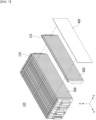
Fig. 1 is a perspective view of a battery module according to an embodiment of the present disclosure; -
Fig. 2 is an exploded perspective view of the battery module ofFig. 1 ; -
Fig. 3 is a plan view showing one of the battery cells included in the battery module ofFig. 2 ; -
Fig. 4 is a cross-sectional view taken along the cutting line A-A' inFig. 1 ; -
Fig. 5 is a cross-sectional view of a battery module according to another embodiment of the present disclosure; -
Fig. 6 is a perspective view showing a battery cell stack according to a comparative example of the present disclosure; -
Fig. 7 is a perspective view showing a battery cell stack according to an embodiment of the present disclosure; and -
Fig. 8 is a plan view showing a state where an adhesion part is formed on one surface of a battery cell according to an embodiment of the present disclosure. - Hereinafter, various embodiments of the present disclosure will be described in detail with reference to the accompanying drawings so that those skilled in the art can easily carry out them. The present disclosure may be modified in various different ways, and is not limited to the embodiments set forth herein.
- Portions that are irrelevant to the description will be omitted to clearly describe the present disclosure, and same reference numerals designate same or like elements throughout the description.
- Further, in the drawings, the size and thickness of each element are arbitrarily illustrated for convenience of description, and the present disclosure is not necessarily limited to those illustrated in the drawings. In the drawings, the thickness of layers, regions, etc. are exaggerated for clarity. In the drawings, for convenience of description, the thicknesses of a part and an area are exaggerated.
- Further, it will be understood that when an element such as a layer, film, region, or plate is referred to as being "on" or "above" another element, it can be directly on the other element or intervening elements may also be present. In contrast, when an element is referred to as being "directly on" another element, it means that other intervening elements are not present. Further, a certain part being located "above" or "on" a reference portion means the certain part being located above or below the reference portion and does not particularly mean the certain part "above" or "on" toward an opposite direction of gravity.
- Further, throughout the description, when a portion is referred to as "including" or "comprising" a certain component, it means that the portion can further include other components, without excluding the other components, unless otherwise stated.
- Further, throughout the description, when it is referred to as "planar", it means when a target portion is viewed from the upper side, and when it is referred to as "cross-sectional", it means when a target portion is viewed from the side of a cross section cut vertically.
-
Fig. 1 is a perspective view of a battery module according to an embodiment of the present disclosure.Fig. 2 is an exploded perspective view of the battery module ofFig. 1 .Fig. 3 is a plan view showing one of the battery cells included in the battery module ofFig. 2 . - Referring to
Figs. 1 to 3 , thebattery module 100 according to an embodiment of the present disclosure includes abattery cell stack 120 formed by stacking a plurality ofbattery cells 110; amodule frame 200 that houses thebattery cell stack 120; and at least onecompression pad 400. - First, the
battery cell 110 may be a pouch-type battery cell. The pouch-type battery cell may be formed by housing an electrode assembly in a pouch case made of a laminate sheet including a resin layer and a metal layer, and then joining the outer peripheral part of the pouch case.Such battery cells 110 may be formed in a rectangular sheet structure. Specifically, thebattery cell 110 according to the present embodiment may have a structure in which two electrode leads 111 and 112 face each other and protrude from oneend 114a and theother end 114b of the cellmain body 113, respectively. Thebattery cell 110 can be produced by joining bothends cell case 114 and oneside part 114c connecting them in a state in which an electrode assembly (not shown) is housed in acell case 114. In other words, thebattery cell 110 according to one embodiment of the present disclosure has a total of three sealing parts, and the remaining other side part may be composed of afolding part 115. Between both ends 114a and 114b of thebattery case 114 may be defined as a longitudinal direction of thebattery cell 110, and between oneside part 114c connecting bothends battery case 114 and thefolding part 115 may be defined as a widthwise direction of thebattery cell 110. - On the other hand, only the
battery cell 110 having a structure in which the electrode leads 111 and 112 protrude in both directions of one side and the other side has been described, but in another embodiment of the present disclosure, it goes without saying that a unidirectional pouch-type battery cell in which electrode leads protrude together in one direction can be used. - The
battery cell 110 may be formed in a plurality of numbers, and the plurality ofbattery cells 110 may be stacked so as to be electrically connected to each other, thereby forming abattery cell stack 120. Thebattery cell case 114 is generally formed in a laminated structure of resin layer/metal thin film layer/resin layer. For example, when the surface of the battery case is formed of an O (oriented)-nylon layer, it tends to slide easily due to external impact when stacking a plurality of battery cells to form a medium- and large-sized battery module. Therefore, in order to prevent this problem and maintain a stable stacked structure of battery cells, an adhesion part can be provided on the surface of the battery case to form abattery cell stack 120. The adhesion part may be provided on the surface of the battery case to form abattery cell stack 120. The adhesion part may be a tacky adhesive such as a double-sided tape or a chemical adhesive bonded by a chemical reaction during adhesion. The adhesion part will be described later. - A plurality of
battery cells 110 are stacked along one direction to form abattery cell stack 120, wherein thebattery cells 110 having a rectangular sheet structure may be stacked along one direction in a state that one surfaces of the cellmain body 113 face each other. More specifically, thebattery cells 110 may be stacked in an upright state so that the one surface of thebattery cells 110 is parallel to theside surface parts module frame 200, which will be described later.Fig. 2 shows a state in whichbattery cells 110 are stacked along a direction parallel to the y-axis to form abattery cell stack 120. Accordingly, in thebattery cell stack 120, the electrode leads 111 and 112 may protrude toward the x-axis direction and the -x-axis direction. - The
module frame 200 may be a frame having a form in which one side and the other side are opened. Thebattery cell stack 120 is inserted through the opened one side or other side of themodule frame 200, so that thebattery cell stack 120 can be housed in the inner space of themodule frame 200. - The
module frame 200 includesside surface parts battery cell stack 120 along the stacking direction of thebattery cells 110. In thebattery cells 110 stacked along the y-axis direction, each of theside surface parts module frame 200 can cover the side surfaces in the y-axis direction and the -y-axis direction of thebattery cell stack 120. - Further, the
module frame 200 may include anupper surface part 230 and alower surface part 240 that connect theside surface parts upper surface part 230 and thelower surface part 240 of themodule frame 200 may respectively cover the upper surface and the lower surface of thebattery cell stack 120 housed in the interior of themodule frame 200. - On the other hand, the
module frame 200 shown inFig. 2 may have a form in which theside surface parts upper surface part 230 and thelower surface part 240 are integrated, but in another embodiment of the present disclosure, the module frame may have a form in which a U-shaped frame and an upper cover are joined together. A U-shaped frame covering both side surfaces and lower surfaces of the battery cell stack and an upper cover covering the upper surface of the battery cell stack may be joined at corresponding corners to form a module frame. - The
battery module 100 according to the present embodiment may include abusbar frame 500 housed in themodule frame 200 together with thebattery cell stack 120. Thebusbar frame 500 may include afront surface frame 510 and arear surface frame 520 that are respectively located on one surface and the other surface of thebattery cell stack 120 from which the electrode leads 111 and 112 protrude. Further, thebusbar frame 500 may further include an upper frame 530 that is connected to each of thefront surface frame 510 and therear surface frame 520 and is located at the upper part of thebattery cell stack 120. - The
busbars 540 for connecting the electrode leads 111 and 112 of thebattery cells 110 included in thebattery cell stack 120 may be mounted on thefront surface frame 510 and therear surface frame 520. Specifically, the electrode leads 111 and 112 of thebattery cell 110 is bent after passing through slits formed in thefront surface frame 510 and therear surface frame 520, and can be joined to thebusbar 540 by welding or the like. In this manner, thebattery cells 110 included in thebattery cell stack 120 may be electrically connected in series or in parallel. - The
battery module 100 according to the present embodiment may includeend plates 300 located on both opened sides of themodule frame 200 facing each other. Theend plates 300 may be provided so as to cover the opened one side and other side of themodule frame 200. That is, the twoend plates 300 may be located on both opened sides of themodule frame 200 and joined at corresponding corners of themodule frame 200 by welding or the like. Theend plate 300 can physically protect thebattery cell stack 120 and other electrical components from external impact. -
Fig. 4 is a cross-sectional view taken along the cutting line A-A' ofFig. 1 . - Referring to
Figs. 2 to 4 together, thebattery module 100 according to the present embodiment includes at least onecompression pad 400 that is disposed at least at one place betweenadjacent battery cells 110 or between thebattery cell 110, located on the outermost side among thebattery cells 110, and theside surface parts - The
compression pad 400 is a foam-shaped member and can partially absorb the swelling of battery cells. Specifically, thebattery cell 110 may generate gas inside due to deterioration or the like as charge/discharge is repeated. And, when gas is generated from the inside in this way, the internal pressure increases, which may cause a swelling phenomenon in which pressure resistance increases and at least a part of the exterior material swells. In particular, in the case of the pouch-type secondary battery, the structural stiffness of the exterior material is weaker than that of the can-type secondary battery, so that the swelling phenomenon may occur more severely. - When a swelling phenomenon occurs in the secondary battery in this way, the pressure inside the battery increases and the volume increases, which may adversely affect the structural stability of the battery module. Thus, by arranging a
compression pad 400 that is compressed when pressure is applied to the interior of thebattery module 100, an attempt was made to partially absorb the swelling of thebattery cell 110. The material of thecompression pad 400 is not particularly limited as long as it can be compressed to absorb the swelling of thebattery cell 110, and may include polyurethane material as an example. - On the other hand, the battery module according to the present embodiment has a reserved space ratio per battery cell of 3% or more, based on the stacking direction of the
battery cells 110. Also, the reserved space ratio per battery cell may be 3% or more and 10% or less. Additionally, considering the space utilization and energy density of the battery module, the reserved space ratio per battery cell may be 3% or more and 6% or less, and may be 4% or more and 6% or less. - The reserved space ratio per battery cell is a value of calculating a space occupied by one of the
battery cells 110 within thebattery module 100, and can be calculated using the following equation.
wherein, the W is the distance value between theside surface parts module frame 200, the C is a value corresponding to the total of thicknesses of thebattery cells 110, and the P is a value corresponding to the total of thicknesses of thecompression pads 400 in a compressed state, in a state where thebattery cell stack 120 and thecompression pads 400 are housed in themodule frame 200. The units of the values of W, C and P may all be "mm". - As shown in
Fig. 4 , the W corresponds to the distance value between the inner side surfaces of theside surface parts module frame 200. As mentioned above, theside surface parts battery cell stack 120 along the stacking direction of thebattery cells 110, which are parts related to the pressing force applied to the battery cell where swelling occurs. - The C is a value corresponding to the total of thicknesses of the
battery cells 110, and can be calculated as the product of the thickness value (Ct) of the central part of asingle battery cell 110 and the number (Cn) of thebattery cells 110. That is, C=Ct*Cn, wherein Ct is a value corresponding to the thickness of the central part of asingle battery cell 110 along the stacking direction (y-axis direction) of thebattery cells 110, and Cn is a value corresponding to the number ofbattery cells 110. As an example, as shown inFig. 4 , the C value can be derived by multiplying the thickness value (Ct) of thesingle battery cell 110 by 12, which is the number (Cn) of thebattery cells 110. Here, the central part of thebattery cell 110 for measuring the thickness value (Ct) refers to the central part of thebattery cell 110 based on the longitudinal direction thereof. More specifically, referring toFig. 3 , the central part may refer to a midpoint between bothends battery cell 110 where the electrode leads 111 and 112 protrude. - The P may be calculated as the product of the thickness value Pt of a
single compression pad 400 and the number Pn ofcompression pads 400, with respect to thecompression pad 400 in a state where thebattery cell stack 120 and thecompression pad 400 are housed and compressed in themodule frame 200. That is, P=Pt*Pn, wherein Pt is a value corresponding to the thickness of asingle compression pad 400 in a compressed state, and Pn is a value corresponding to the number ofcompression pads 400. As an example, as shown inFig. 4 , the P value can be derived by multiplying the thickness value Pt of asingle compression pad 400 by 4, which is the number Pn of thecompression pads 400. - Next, a battery module according to another embodiment of the present disclosure will be described with reference to
Fig. 5 . -
Fig. 5 is a cross-sectional view of a battery module according to another embodiment of the present disclosure, which corresponds to a cross section of the battery module taken along the yz plane, similarly toFig. 4 . - Referring to
Fig. 5 , thebattery module 100 according to the present embodiment may further comprise at least oneadhesion part 600 that is located betweenbattery cells 110 facing each other among thebattery cells 110, between thebattery cell 110 and thecompression pad 400, or at least at one place of the inner side surfaces of theside surface parts side surface parts battery cell stack 120 among the surfaces of theside surface parts battery cell stack 120,module frame 200, andcompression pad 400 included in thebattery module 100, the same configurations as those previously described in the embodiments ofFigs. 1 to 4 are applied, and therefore, a description thereof will be omitted. - As mentioned above, a plurality of
battery cells 110 are stacked to form a medium- and large-sized battery module 100, but in order to maintain a stable stacked structure of thebattery cells 110, anadhesion part 600 is provided on one surface of thebattery cells 110. - Not only the
adhesion part 600 may be provided between thebattery cells 110, but also when thecompression pad 400 is located between thebattery cells 110, theadhesion part 600 can be provided even between thebattery cell 110 and thecompression pad 400. Additionally, theadhesion parts 600 may also be provided on the inner side surfaces of theside surface parts compression pad 400 is disposed between thebattery cell 110, located on the outermost side among thebattery cells 110, and theside surface parts adhesion part 600 may be provided between thecompression pads 400 and theside surface parts - Specifically, in
Fig. 5 , anadhesion part 600 located between thebattery cells 110 and adhered to one surface of eachadjacent battery cell 110, anadhesion part 600 adhered between thebattery cell 110 and thecompression pad 400, and anadhesion part 600 adhered between thecompression pads 400 and theside surface parts - Although not shown in the figure, in another embodiment of the present disclosure in which the
compression pad 400 is not located between thebattery cell 110, located on the outermost side of thebattery cells 110, and theside surface parti adhesion part 600 may be provided between thebattery cell 110, located on the outermost side of thebattery cells 110, and theside surface part - The
adhesion part 600 according to the present embodiment can be applied without limitation as long as it is a material or member that has adhesive properties. As an example, theadhesion part 600 may be a double-sided tape. As another example, theadhesion part 600 may be an adhesion layer formed by applying an adhesive. - At this time, the battery module according to the present embodiment has a reserved space ratio per battery cell of 3% or more based on the stacking direction of the
battery cells 110. - In the present embodiment, the reserved space ratio per battery cell can be calculated by the following equation.

side surface parts module frame 200, the C is a value corresponding to the total of thicknesses of thebattery cells 110, the P is a value corresponding to the total of thicknesses of thecompression pads 400 in a compressed state, in a state where thebattery cell stack 120 and thecompression pads 400 are housed in themodule frame 200, and the D is a value corresponding to the total of thicknesses of theadhesion parts 600. The units of the values of W, C, P and D may all be mm. - As shown in
Fig. 5 , the W corresponds to the distance value between the inner surfaces of theside surface parts module frame 200. - The C is a value corresponding to the total of thicknesses of the
battery cells 110, and can be calculated as the product of the thickness value Ct of the central of asingle battery cell 110 and the number Cn of thebattery cells 110. That is, C=Ct*Cn, wherein Ct is a value corresponding to the thickness of the central part of asingle battery cell 110 along the stacking direction (y-axis direction) of thebattery cells 110, and Cn is a value corresponding to the number ofbattery cells 110. As an example, as shown inFig. 5 , the C value can be derived by multiplying the thickness value Ct of thesingle battery cell 110 by 12, which is the number Cn of thebattery cells 110. Here, the central part of thebattery cell 110 for measuring the thickness value Ct refers to the central part of thebattery cell 110 based on the longitudinal direction thereof. More specifically, referring toFig. 3 , the central part of thebattery cell 110 may refer to a midpoint between bothends battery cell 110 from which the electrode leads 111 and 112 protrude. - The P may be calculated as the product of the thickness value Pt of the
single compression pad 400 and the number Pn ofcompression pads 400, with respect to thecompression pad 400 in a state where thebattery cell stack 120 and thecompression pad 400 are housed together and compressed in themodule frame 200. That is, P=Pt*Pn, wherein Pt is a value corresponding to the thickness of asingle compression pad 400 in a compressed state, and Pn is a value corresponding to the number ofcompression pads 400. As an example, as shown inFig. 5 , the P value can be derived by multiplying the thickness (Pt) of thesingle compression pad 400 by 4, which is the number Pn of thecompression pads 400. - The D may be calculated as the product of the thickness Dt of a
single adhesion part 600 and the number Dn of theadhesion parts 600. That is, D=Dt*Dn, wherein Dt is a value corresponding to the thickness of asingle adhesion part 600, and Dn is a value corresponding to the number of theadhesion parts 600. As an example, theadhesion part 600 may be located between thebattery cells 110 and between thebattery cells 110 and thecompression pad 400. Moreover, when thecompression pad 400 or thebattery cell 110 is located on the outermost side, theadhesion part 600 may also be disposed on thecompression pad 400 located on the outermost side or on the outer surface of thebattery cell 110. Theadhesion part 600 may also be located between thecompression pad 400, located on the outermost side, or thebattery cell 110 and theside surface parts adhesion part 600 may be provided on the inner side surface of theside surface parts battery cell 110 and thecompression pad 400 are considered as one component, theadhesion parts 600 can be interposed between these components. The number Dn of theadhesion parts 600 may be calculated as the sum of the number Cn of thebattery cells 110 and the number Pn of thecompression pads 400 plus 1. As an example, referring to the example ofFig. 5 in which 12battery cells 110 and 4compression pads 400 are arranged in the interior of themodule frame 200, a total of 17adhesion parts 600 may be provided. In this case, D is the value of multiplying the thickness Dt of thesingle adhesion part 600 by 17, which is the number Dn of theadhesion parts 600. - Taken together, in the case of a battery module in which no adhesion part is provided, the reserved space ratio per battery cell is calculated as (W-C-P)/C*100, and in the case of a battery module in which an adhesion part is provided, the reserved space ratio per battery cell can be calculated as (W-C-P-D)/C*100. In the
battery module 100 of the present embodiment, the values of the calculated reserved space ratio are all 3% or more. - The present inventors have confirmed that the space occupied by the
battery cells 110 within thebattery module 100, in other words, the pressing force applied to thebattery cells 110, affects the life performance of thebattery module 100. When an appropriate level of pressing force is applied to thebattery cell 110, an appropriate capacity can be maintained even if the cycle of thebattery module 100 progresses. When the pressing force is below or above a certain level, there may arise a problem that a sudden drop in capacity may occur during the progress of cycle. Based on this, the present inventors have designed the conditions where the reserved space ratio per battery cell is 3% or more in order to control the absolute pressure applied to thebattery cells 110 within thebattery module 100, and confirmed that when this condition is satisfied, no deterioration in life performance occur when thebattery cell 110 is attached to thebattery module 100. Specifically, in the case of a battery module that satisfies the conditions, the capacity retention after 800 cycles can be maintained at 80% or more. - Below, the battery module of the present disclosure will be described with reference to specific examples and comparative examples.
[Table 1] Example 1 Example 2 Example 3 Example 4 Distance between the inner side surfaces of the side surface parts of the module frame (W) [mm] 213 148 217.6 217.6 Total of thicknesses of battery cells (C) [mm] 202.32 139.44 205.2 206.88 Total of thicknesses of compression pads in compressed state (P) [mm] 1.8 1.76 1.8 1.8 Total of thicknesses of adhesion parts (D) 1.5 0.85 1.5 1.5 Reserved space ratio per battery cell [%] 3.65 4.27 4.43 3.59 Capacity retention after 800 cycles in battery cell unit [%] 90 89.3 80 80 Capacity retention after 800 cycles in battery module unit [%] 85 89 81 79 Difference in capacity degradation between battery cells and battery modules [%] 5 0.3 -1 1 - First, referring to Table 1, the battery modules having different standards and specifications were prepared in Examples 1 to 4, and the reserved space ratio (%) per battery cell for the battery modules in Examples 1 to 4 was calculated. The units of each factor were listed in square brackets.
- As mentioned above, W is a measurement value of the distance between the inner side surfaces of the
side surface parts module frame 200. The C, which corresponds to the total of thicknesses of thebattery cells 110, was calculated as the product of the thickness value Ct of the central part of thebattery cell 110 and the number Cn ofbattery cells 110. - It has been confirmed that the
compression pad 400 is compressed by 80% when inserted into themodule frame 200 together with thebattery cell 110, and the thickness value Pt of thecompression pad 400 in a compressed state was calculated as 20% of the thickness of theoriginal compression pad 400 before compression. The P corresponding to the total value of thicknesses of the compression pads in a compressed state can be calculated as the product of the thickness value Pt of thecompression pad 400 in a compressed state and the number Pn of thecompression pads 400. - The D, which corresponds to the total of thicknesses of the
adhesion parts 600, can be calculated as the product of the thickness Dt of thesingle adhesion part 600 and the number Dn of theadhesion parts 600. In the case of the battery modules in Examples 1 to 4, theadhesion part 600 is located betweenadjacent battery cells 110, between thebattery cells 110 and thecompression pad 400, and on thecompression pad 400 located on the outermost side and the outer surface of thebattery cell 110. In Examples 1 to 4, the number of theadhesion parts 600 was calculated as the sum of the number Cn of thebattery cells 110 and the number Pn of thecompression pads 400 plus 1. - The reserved space ratio [%] per battery cell was calculated using the derived W, C, P and D values of Examples 1 to 4, and Examples 1 to 4 were calculated to have reserved space ratio values per battery cell of 3.65%, 4.27%, 4.43%, and 3.59%, respectively. The reserved space ratio per battery cell in Examples 1 to 4 is all the values of 3% or more.
- For Examples 1 to 4, the reserved capacity ratio [%] after 800 cycles in the battery cell unit and the reserved capacity ratio [%] after 800 cycles in the battery module unit were measured. The capacity retention after 800 cycles in a battery cell unit is a measurement value of the discharge capacity after 800 cycles of charging and discharging for a single battery cell that is not composed of a battery module relative to the initial discharge capacity. The capacity retention after 800 cycles in the battery module unit is a measurement value of the discharge capacity after 800 cycles of charge and discharge for the battery module containing the corresponding battery cells, as compared to the initial discharge capacity.
- Looking at the difference between the capacity retention after 800 cycles in the battery cell unit and the capacity retention after 800 cycles in the battery module unit, that is, the difference in capacity degradation [%] between the battery cell and the battery module, Examples 1 to 4 were measured as the values of 5, 0.3, -1, and 1, respectively.
- In the case of Examples 1 to 4 in which the reserved space ratio per battery cell is all 3% or more, it was confirmed that even if the
battery cells 110 were composed of thebattery module 100, there was no significant decrease in life performance. There was no large difference in the capacity retention after 800 cycles in the battery cell unit and the battery module unit. In other words, even if the cycle of thebattery module 100 progresses, an appropriate capacity can be maintained, and the problem of a sudden drop in capacity during progress of the cycle does not occur.[Table 2] Comparative Example 1 Comparative Example 2 Comparative Example 3 Distance between the inner side surfaces of the side surface parts of module frame (W) [mm] 216.2 216.2 217.6 Total of thicknesses of battery cells (C) [mm] 208.968 208.968 209.16 Total of thicknesses of compression pads in compressed state (P) [mm] 1.8 1.8 1.8 Total of thicknesses of adhesion part (D) 1.4 1.5 1.5 Reserved space ratio per battery cell [%] 1.93 1.88 2.46 Capacity retention after 800 cycles in battery cell unit [%] 80 80 80 Capacity retention after 800 cycles in battery module unit [%] 61.2 61.2 64.2 Difference in capacity degradation between battery cells and battery modules [%] 18.8 18.8 15.8 - Next, referring to Table 2, the battery modules having different standards and specifications were prepared in Comparative Examples 1 to 3, and the reserved space ratio (%) per battery cell for the battery modules in Comparative Examples 1 to 3 was calculated. The units of each factor were listed in square brackets.
- The W, C, P and D values for Comparative Examples 1 to 3 were derived similarly to the method measured in Examples 1 to 4. Descriptions thereof are omitted because they overlap with the contents previously described.
- The reserved space ratio [%] per battery cell was calculated using the derived W, C, P and D values of Comparative Examples 1 to 3, and Examples 1 to 3 were calculated to have reserved space ratio values per battery cell of 1.93%, 1.88%, and 2.46%, respectively. The reserved space ratio per battery cell in Comparative Examples 1 to 3 is all the values of less than 3%.
- The capacity retention after 800 cycles, the capacity retention after 800 cycles in the battery module unit, and the difference in capacity degradation between battery cells and battery modules were calculated similarly to the method measured in Examples 1 to 4. Looking at the difference [%] in capacity degradation between battery cells and battery modules, Comparative Examples 1 to 3 were measured to be 18.8, 18.8, and 15.8, respectively.
- In the case of Comparative Examples 1 to 3 in which the reserved space ratio per battery cell is all less than 3%, it was confirmed that when the
battery cells 110 were composed of thebattery module 100, a significant decrease in life performance occurred as compared to Examples 1 to 4. In other words, similarly to the battery module according to the present embodiment, when the reserved space ratio per battery cell satisfies the condition of 3% or more, it was confirmed through the above experimental results that it is possible to prevent a large decrease in the life performance of the battery module. - Next, referring to
Figs. 6 to 8 , the formation area of theadhesion part 600 according to an embodiment of the present disclosure will be described in detail along with Comparative Examples. -
Fig. 6 is a perspective view showing a battery cell stack according to a comparative example of the present disclosure. - First, referring to
Fig. 6 , a plurality ofbattery cells 11 are stacked to form abattery cell stack 12, and anadhesion part 60 may be provided at least at one place between thebattery cells 11. Thisadhesion part 60 may be a double-sided tape, or an adhesion layer formed by applying an adhesive. As shown inFig. 6 , theadhesion part 60 according to the present comparative example is not attached to the whole of one surface where thebattery cells 11 face each other, but only to a portion thereof. In this case, the present inventors have confirmed that uneven pressure is applied to thebattery cell 110 due to the partially formedadhesion part 60, and lithium plating (Li-Plating) occurs at both ends. - Specifically, uneven surface pressure on the surface of the
battery cell 110 occurs due to the partially formedadhesion part 60, and gas generated by the uneven surface pressure exists on the surface of the battery cell, which causes Li-plating in which lithium is precipitated on the surface of thebattery cell 110. In particular, referring toFigs. 3 and6 together, when theadhesion part 60 is formed only in the central part of thebattery cell 110, the inventors have found a problem in which lithium mainly precipitates in areas adjacent to bothends battery cell 110 from which the electrode leads 111 and 112 protrude. - The present inventors have analyzed the relationship between the lithium precipitation rate in Li-plating and the capacity retention of the battery cell, and confirmed that the lithium precipitation rate and the capacity retention of the battery cell have a strong negative correlation. That is, as the lithium precipitation rate increases, the capacity retention after 800 cycles decreases. Non-uniform surface pressure of the
battery cell 110 resulting from theadhesion part 60 adversely affects the life performance of thebattery module 100. Accordingly, the present inventors have proposed the followingadhesion part 600 as a uniform pressure structure on the surface of thebattery cell 110. Next, the formation area of theadhesion part 600 according to this embodiment will be described with reference toFigs. 3 ,7 and8 . -
Fig. 7 is a perspective view showing a battery cell stack according to an embodiment of the present disclosure.Fig. 8 is a plan view showing a state where an adhesion part is formed on one surface of a battery cell according to an embodiment of the present disclosure. - Referring to
Figs. 3 ,7 and8 , as mentioned above, thebattery cells 110 are sheet-shaped pouch-type battery cells, and may be stacked in an upright state so that one surface of thebattery cells 110 is parallel to theside surface parts 210 and 220 (seeFig. 2 ). Thebattery cells 110 may be stacked so that the one surfaces of the battery cells face each other. That is, the one surface of thebattery cells 110 described below corresponds to a portion of thebattery cell 110 that is parallel to theside surface parts module frame 200, and may face anotherbattery cell 110, acompression pad 400, orside surface parts module frame 200. - At this time, the
adhesion part 600 according to the present embodiment may be attached to the one surface of thebattery cells 110 so as to cover the one surface of thebattery cells 110. Specifically, theadhesion part 600 may be attached to the one surface of thebattery cells 110 so as to cover an area of 90% or more and 100% or less of the area of the one surface of thebattery cells 110. In addition, considering the design tolerance for the one surface of thebattery cells 110, theadhesion part 600 may be attached to the one surface of thebattery cells 110 so as to cover an area of 90% or more and 101% or less of the area of the one surface of thebattery cells 110. - Unlike the
adhesion part 60 according to the comparative example described above, theadhesion part 600 according to this embodiment may be attached so as to cover most of the surface of thebattery cell 110. Accordingly, a uniform pressing structure on the one surface of thebattery cells 110 can be realized. Unlike theadhesion part 60, which was attached only to a narrow area, theadhesion part 600 according to the present embodiment can ensure uniformity of the pressure applied to the surface of thebattery cell 110, which solves the problem of lithium plating occurring in the portion adjacent to bothends battery cell 110, and can improve the life performance of thebattery module 100. - On the other hand, referring to
Figs. 4 and5 , thebattery module 100 according to the present embodiment may further include a thermallyconductive resin layer 700 located between thebattery cell stack 120 and thelower surface 240 of themodule frame 200. - The thermally
conductive resin layer 700 may be formed by applying a thermally conductive resin to thelower surface 240 and curing the applied thermally conductive resin, or may be formed by injecting a thermally conductive resin through a through hole formed in thelower surface part 240. In particular, in thebattery cell 110 in which the electrode leads 111 and 112 protrude in both opposing directions, the portion of thebattery cell stack 120 adjacent to the electrode leads 111 and 112 of thebattery cell 110 generates excessive heat. The thermallyconductive resin layer 700 may be formed divided into two zones so as to correspond to both parts of thebattery cell stack 120 that generates excessive heat. - The thermally conductive resin may include a thermally conductive adhesive material, and specifically, it may include at least one of silicone material, urethane material, and acrylic material. The thermally conductive resin may be in a liquid state during application or injection, and may be cured after application or injection to thereby serve to fix one or
more battery cells 110 constituting thebattery cell stack 120. In addition, it has excellent heat conduction characteristics, allowing heat generated in thebattery cell 110 to be quickly transferred to the lower side of the battery module. - The terms representing directions such as the front side, the rear side, the left side, the right side, the upper side, and the lower side have been used in the present embodiment, but the terms used are provided simply for convenience of description and may become different according to the position of an object, the position of an observer, or the like.
- The one or more battery modules according to embodiments of the present disclosure described above can be mounted together with various control and protection systems such as a BMS (battery management system), a BDU(battery disconnect unit), and a cooling system to form a battery pack.
- The battery pack can be applied to various devices. For example, it can be applied to vehicle means such as an electric bike, an electric vehicle, and a hybrid electric vehicle, or an ESS (Energy Storage System) and may be applied to various devices capable of using a secondary battery, without being limited thereto.
- Although the invention has been described in detail with reference to preferred embodiments of the present disclosure, the scope of the present disclosure is not limited thereto, and various modifications and improvements can be made by those skilled in the art using the basic concepts of the present disclosure, which are defined in the appended claims, which also falls within the scope of the present disclosure.
-
- 100: battery module
- 110: battery cell
- 120: battery cell stack
- 200: module frame
- 300: end plate
- 400: compression pad
- 500: busbar frame
- 600: adhesion part
Claims (17)
- A battery module comprising:a battery cell stack formed by stacking a plurality of battery cells;a module frame that houses the battery cell stack and includes side surface parts respectively covering both side surfaces of the battery cell stack along the stacking direction of the battery cells; andat least one compression pad that is disposed at least at one place between adjacent battery cells among the battery cells or between the battery cell, located on the outermost side among the battery cells, and the side surface parts,wherein a reserved space ratio per battery cell is 3% or more, based on the stacking direction of the battery cells.
- The battery module of claim 1, wherein:
the reserved space ratio per battery cell is 3% or more and 10% or less, based on the stacking direction of the battery cells. - The battery module of claim 1, wherein:
the reserved space ratio per battery cell is calculated as (W-C-P)/C* 100, wherein:the W is the distance value between the side surface parts of the module frame,the C is a value corresponding to the total of thicknesses of the battery cells, andthe P is a value corresponding to the total of thicknesses of the compression pads in a compressed state, in a state where the battery cell stack and the compression pads are housed in the module frame. - The battery module of claim 3, wherein:
the C is a value of multiplying the thickness value of a central part of the battery cell by the number of battery cells. - The battery module of claim 3, wherein:
the P is a value of multiplying the thickness value of the compression pads in a compressed state by the number of the compression pads. - The battery module of claim 1, wherein:the battery cells are sheet-shaped pouch-type battery cells, andthe battery cells are stacked in an upright state so that one surface of the battery cells is parallel to the side surface part.
- The battery module of claim 1, further comprising:
at least one adhesion part that is located between battery cells facing each other among the battery cells, between the battery cell and the compression pad, or at least at one place of the inner side surfaces of the side surface parts. - The battery module of claim 7, wherein:
the adhesion part is a double-sided tape or an adhesion layer formed by applying an adhesive. - The battery module of claim 7, wherein:
the reserved space ratio per battery cell is calculated as (W-C-P-D)/C*100, wherein:the W is the value of the space between the side surface parts of the module frame,the C is a value corresponding to the total of thicknesses of the battery cells,the P is a value corresponding to the total of thicknesses of the compression pads in a compressed state, in a state where the battery cell stack and the compression pads are housed in the module frame, andthe D is a value corresponding to the total of thicknesses of the adhesion parts. - The battery module of claim 9, wherein:
the C is a value of multiplying the thickness value of a central part of the battery cell by the number of battery cells. - The battery module of claim 9, wherein:
the P is a value of multiplying the thickness value of the compression pads in a compressed state by the number of the compression pads. - The battery module of claim 9, wherein:
the D is a value of multiplying the thickness value of the adhesion part by the number of adhesion parts. - The battery module of claim 7, wherein:the battery cells are sheet-shaped pouch-type battery cells, andthe battery cells are stacked in an upright state so that one surface of the battery cells is parallel to the side surface part.
- The battery module of claim 13, wherein:
the adhesion part is attached to the one surface of the battery cells so as to cover the one surface of the battery cells. - The battery module of claim 13, wherein:
the adhesion part is attached to the one surface of the battery cells so as to cover an area of 90% or more and 100% or less of the area of the one surface of the battery cells. - The battery module of claim 13, wherein:
the adhesion part is attached to the one surface of the battery cells so as to cover an area of 90% or more and 101% or less of the area of the one surface of the battery cells. - A battery pack comprising the battery module of claim 1.
Applications Claiming Priority (1)
| Application Number | Priority Date | Filing Date | Title |
|---|---|---|---|
| PCT/KR2023/013525 WO2025053312A1 (en) | 2023-09-08 | 2023-09-08 | Battery module and battery pack including same |
Publications (2)
| Publication Number | Publication Date |
|---|---|
| EP4576362A1 true EP4576362A1 (en) | 2025-06-25 |
| EP4576362A4 EP4576362A4 (en) | 2026-04-22 |
Family
ID=94923790
Family Applications (1)
| Application Number | Title | Priority Date | Filing Date |
|---|---|---|---|
| EP23951598.4A Pending EP4576362A4 (en) | 2023-09-08 | 2023-09-08 | BATTERY MODULE AND BATTERY PACK SO THAT |
Country Status (4)
| Country | Link |
|---|---|
| EP (1) | EP4576362A4 (en) |
| JP (1) | JP2025532181A (en) |
| CN (1) | CN120019535A (en) |
| WO (1) | WO2025053312A1 (en) |
Family Cites Families (7)
| Publication number | Priority date | Publication date | Assignee | Title |
|---|---|---|---|---|
| WO2014141753A1 (en) * | 2013-03-12 | 2014-09-18 | Necエナジーデバイス株式会社 | Power cell module |
| KR101792820B1 (en) * | 2014-12-22 | 2017-11-01 | 주식회사 엘지화학 | Battery Pack Comprising Terminal Connecting Member with Breakable Portion and Damping Member |
| KR102067713B1 (en) * | 2016-05-31 | 2020-01-17 | 주식회사 엘지화학 | Battery module, battery pack comprising the battery module and vehicle comprising the battery pack |
| TWI754943B (en) * | 2020-05-28 | 2022-02-11 | 廣達電腦股份有限公司 | Smart battery device |
| KR102893615B1 (en) * | 2020-11-13 | 2025-12-01 | 에스케이온 주식회사 | Battery Module and Battery Pack Having the same |
| US20230411760A1 (en) * | 2021-04-05 | 2023-12-21 | Lg Energy Solution, Ltd. | Battery module including compression pad having improved insulation and assembly, battery pack and vehicle including the same |
| KR20240011504A (en) * | 2022-07-19 | 2024-01-26 | 주식회사 엘지에너지솔루션 | Battery module and battery pack including the same |
-
2023
- 2023-09-08 JP JP2025517651A patent/JP2025532181A/en active Pending
- 2023-09-08 EP EP23951598.4A patent/EP4576362A4/en active Pending
- 2023-09-08 WO PCT/KR2023/013525 patent/WO2025053312A1/en active Pending
- 2023-09-08 CN CN202380072197.7A patent/CN120019535A/en active Pending
Also Published As
| Publication number | Publication date |
|---|---|
| JP2025532181A (en) | 2025-09-29 |
| WO2025053312A1 (en) | 2025-03-13 |
| EP4576362A4 (en) | 2026-04-22 |
| CN120019535A (en) | 2025-05-16 |
Similar Documents
| Publication | Publication Date | Title |
|---|---|---|
| EP3958379B1 (en) | Battery module and battery pack including the same | |
| EP4184706B1 (en) | Battery module, battery pack including same, and manufacturing method thereof | |
| US12542313B2 (en) | Battery module and battery pack including the same | |
| EP4181293A1 (en) | Battery module and battery pack including same | |
| US20230402678A1 (en) | Battery Pack and Device Including the Same | |
| US20240047806A1 (en) | Battery module and battery pack including the same | |
| EP4184666A1 (en) | Battery pack and device including same | |
| US20260088421A1 (en) | Battery module and battery pack including the same | |
| EP4266457A1 (en) | Battery module and battery pack comprising same | |
| EP4181275B1 (en) | Battery module and battery pack including same | |
| US20230318078A1 (en) | Battery module and battery pack including the same | |
| EP4089799A1 (en) | Battery module and battery pack including same | |
| EP4391156A1 (en) | Battery pack and device comprising same | |
| EP4181292B1 (en) | Battery pack including battery modules | |
| US20250132408A1 (en) | Temperature sensing member, battery module and battery pack including the same | |
| EP4250463A1 (en) | Battery module and battery pack comprising same | |
| EP4539227A1 (en) | Battery pack and device including the same | |
| US20240113357A1 (en) | Battery pack and device including the same | |
| US12620649B2 (en) | Battery module and manufacturing method of the same | |
| EP4250452A1 (en) | Battery pack and device including same | |
| US20240293691A1 (en) | Battery module and battery pack including the same | |
| CN120019535A (en) | Battery module and battery pack including the battery module | |
| KR102910521B1 (en) | Battery module and battery pack including the same | |
| KR20240115738A (en) | Battery module and battery pack including the same | |
| KR20250164906A (en) | Battery module and battery pack including the same |
Legal Events
| Date | Code | Title | Description |
|---|---|---|---|
| STAA | Information on the status of an ep patent application or granted ep patent |
Free format text: STATUS: THE INTERNATIONAL PUBLICATION HAS BEEN MADE |
|
| PUAI | Public reference made under article 153(3) epc to a published international application that has entered the european phase |
Free format text: ORIGINAL CODE: 0009012 |
|
| STAA | Information on the status of an ep patent application or granted ep patent |
Free format text: STATUS: REQUEST FOR EXAMINATION WAS MADE |
|
| 17P | Request for examination filed |
Effective date: 20250321 |
|
| AK | Designated contracting states |
Kind code of ref document: A1 Designated state(s): AL AT BE BG CH CY CZ DE DK EE ES FI FR GB GR HR HU IE IS IT LI LT LU LV MC ME MK MT NL NO PL PT RO RS SE SI SK SM TR |
|
| A4 | Supplementary search report drawn up and despatched |
Effective date: 20260323 |
|
| RIC1 | Information provided on ipc code assigned before grant |
Ipc: H01M 50/242 20210101AFI20260317BHEP Ipc: H01M 50/211 20210101ALI20260317BHEP Ipc: H01M 10/04 20060101ALI20260317BHEP Ipc: H01M 10/647 20140101ALI20260317BHEP Ipc: H01M 50/209 20210101ALI20260317BHEP Ipc: H01M 50/231 20210101ALI20260317BHEP Ipc: H01M 50/289 20210101ALI20260317BHEP Ipc: H01M 50/105 20210101ALI20260317BHEP Ipc: H01M 50/291 20210101ALI20260317BHEP |