EP4576361A1 - Battery pack and vehicle comprising same - Google Patents
Battery pack and vehicle comprising same Download PDFInfo
- Publication number
- EP4576361A1 EP4576361A1 EP23875141.6A EP23875141A EP4576361A1 EP 4576361 A1 EP4576361 A1 EP 4576361A1 EP 23875141 A EP23875141 A EP 23875141A EP 4576361 A1 EP4576361 A1 EP 4576361A1
- Authority
- EP
- European Patent Office
- Prior art keywords
- insulating member
- gasket
- battery
- battery module
- battery pack
- Prior art date
- Legal status (The legal status is an assumption and is not a legal conclusion. Google has not performed a legal analysis and makes no representation as to the accuracy of the status listed.)
- Pending
Links
Images




Classifications
-
- H—ELECTRICITY
- H01—ELECTRIC ELEMENTS
- H01M—PROCESSES OR MEANS, e.g. BATTERIES, FOR THE DIRECT CONVERSION OF CHEMICAL ENERGY INTO ELECTRICAL ENERGY
- H01M50/00—Constructional details or processes of manufacture of the non-active parts of electrochemical cells other than fuel cells, e.g. hybrid cells
- H01M50/20—Mountings; Secondary casings or frames; Racks, modules or packs; Suspension devices; Shock absorbers; Transport or carrying devices; Holders
- H01M50/233—Mountings; Secondary casings or frames; Racks, modules or packs; Suspension devices; Shock absorbers; Transport or carrying devices; Holders characterised by physical properties of casings or racks, e.g. dimensions
- H01M50/24—Mountings; Secondary casings or frames; Racks, modules or packs; Suspension devices; Shock absorbers; Transport or carrying devices; Holders characterised by physical properties of casings or racks, e.g. dimensions adapted for protecting batteries from their environment, e.g. from corrosion
-
- B—PERFORMING OPERATIONS; TRANSPORTING
- B60—VEHICLES IN GENERAL
- B60L—PROPULSION OF ELECTRICALLY-PROPELLED VEHICLES; SUPPLYING ELECTRIC POWER FOR AUXILIARY EQUIPMENT OF ELECTRICALLY-PROPELLED VEHICLES; ELECTRODYNAMIC BRAKE SYSTEMS FOR VEHICLES IN GENERAL; MAGNETIC SUSPENSION OR LEVITATION FOR VEHICLES; MONITORING OPERATING VARIABLES OF ELECTRICALLY-PROPELLED VEHICLES; ELECTRIC SAFETY DEVICES FOR ELECTRICALLY-PROPELLED VEHICLES
- B60L3/00—Electric devices on electrically-propelled vehicles for safety purposes; Monitoring operating variables, e.g. speed, deceleration or energy consumption
- B60L3/0007—Measures or means for preventing or attenuating collisions
-
- B—PERFORMING OPERATIONS; TRANSPORTING
- B60—VEHICLES IN GENERAL
- B60L—PROPULSION OF ELECTRICALLY-PROPELLED VEHICLES; SUPPLYING ELECTRIC POWER FOR AUXILIARY EQUIPMENT OF ELECTRICALLY-PROPELLED VEHICLES; ELECTRODYNAMIC BRAKE SYSTEMS FOR VEHICLES IN GENERAL; MAGNETIC SUSPENSION OR LEVITATION FOR VEHICLES; MONITORING OPERATING VARIABLES OF ELECTRICALLY-PROPELLED VEHICLES; ELECTRIC SAFETY DEVICES FOR ELECTRICALLY-PROPELLED VEHICLES
- B60L3/00—Electric devices on electrically-propelled vehicles for safety purposes; Monitoring operating variables, e.g. speed, deceleration or energy consumption
- B60L3/0023—Detecting, eliminating, remedying or compensating for drive train abnormalities, e.g. failures within the drive train
- B60L3/0046—Detecting, eliminating, remedying or compensating for drive train abnormalities, e.g. failures within the drive train relating to electric energy storage systems, e.g. batteries or capacitors
-
- B—PERFORMING OPERATIONS; TRANSPORTING
- B60—VEHICLES IN GENERAL
- B60L—PROPULSION OF ELECTRICALLY-PROPELLED VEHICLES; SUPPLYING ELECTRIC POWER FOR AUXILIARY EQUIPMENT OF ELECTRICALLY-PROPELLED VEHICLES; ELECTRODYNAMIC BRAKE SYSTEMS FOR VEHICLES IN GENERAL; MAGNETIC SUSPENSION OR LEVITATION FOR VEHICLES; MONITORING OPERATING VARIABLES OF ELECTRICALLY-PROPELLED VEHICLES; ELECTRIC SAFETY DEVICES FOR ELECTRICALLY-PROPELLED VEHICLES
- B60L50/00—Electric propulsion with power supplied within the vehicle
- B60L50/50—Electric propulsion with power supplied within the vehicle using propulsion power supplied by batteries or fuel cells
- B60L50/60—Electric propulsion with power supplied within the vehicle using propulsion power supplied by batteries or fuel cells using power supplied by batteries
- B60L50/64—Constructional details of batteries specially adapted for electric vehicles
-
- B—PERFORMING OPERATIONS; TRANSPORTING
- B60—VEHICLES IN GENERAL
- B60L—PROPULSION OF ELECTRICALLY-PROPELLED VEHICLES; SUPPLYING ELECTRIC POWER FOR AUXILIARY EQUIPMENT OF ELECTRICALLY-PROPELLED VEHICLES; ELECTRODYNAMIC BRAKE SYSTEMS FOR VEHICLES IN GENERAL; MAGNETIC SUSPENSION OR LEVITATION FOR VEHICLES; MONITORING OPERATING VARIABLES OF ELECTRICALLY-PROPELLED VEHICLES; ELECTRIC SAFETY DEVICES FOR ELECTRICALLY-PROPELLED VEHICLES
- B60L50/00—Electric propulsion with power supplied within the vehicle
- B60L50/50—Electric propulsion with power supplied within the vehicle using propulsion power supplied by batteries or fuel cells
- B60L50/60—Electric propulsion with power supplied within the vehicle using propulsion power supplied by batteries or fuel cells using power supplied by batteries
- B60L50/66—Arrangements of batteries
-
- B—PERFORMING OPERATIONS; TRANSPORTING
- B60—VEHICLES IN GENERAL
- B60L—PROPULSION OF ELECTRICALLY-PROPELLED VEHICLES; SUPPLYING ELECTRIC POWER FOR AUXILIARY EQUIPMENT OF ELECTRICALLY-PROPELLED VEHICLES; ELECTRODYNAMIC BRAKE SYSTEMS FOR VEHICLES IN GENERAL; MAGNETIC SUSPENSION OR LEVITATION FOR VEHICLES; MONITORING OPERATING VARIABLES OF ELECTRICALLY-PROPELLED VEHICLES; ELECTRIC SAFETY DEVICES FOR ELECTRICALLY-PROPELLED VEHICLES
- B60L58/00—Methods or circuit arrangements for monitoring or controlling batteries or fuel cells, specially adapted for electric vehicles
- B60L58/10—Methods or circuit arrangements for monitoring or controlling batteries or fuel cells, specially adapted for electric vehicles for monitoring or controlling batteries
- B60L58/18—Methods or circuit arrangements for monitoring or controlling batteries or fuel cells, specially adapted for electric vehicles for monitoring or controlling batteries of two or more battery modules
- B60L58/21—Methods or circuit arrangements for monitoring or controlling batteries or fuel cells, specially adapted for electric vehicles for monitoring or controlling batteries of two or more battery modules having the same nominal voltage
-
- H—ELECTRICITY
- H01—ELECTRIC ELEMENTS
- H01M—PROCESSES OR MEANS, e.g. BATTERIES, FOR THE DIRECT CONVERSION OF CHEMICAL ENERGY INTO ELECTRICAL ENERGY
- H01M10/00—Secondary cells; Manufacture thereof
- H01M10/60—Heating or cooling; Temperature control
- H01M10/65—Means for temperature control structurally associated with the cells
- H01M10/658—Means for temperature control structurally associated with the cells by thermal insulation or shielding
-
- H—ELECTRICITY
- H01—ELECTRIC ELEMENTS
- H01M—PROCESSES OR MEANS, e.g. BATTERIES, FOR THE DIRECT CONVERSION OF CHEMICAL ENERGY INTO ELECTRICAL ENERGY
- H01M50/00—Constructional details or processes of manufacture of the non-active parts of electrochemical cells other than fuel cells, e.g. hybrid cells
- H01M50/20—Mountings; Secondary casings or frames; Racks, modules or packs; Suspension devices; Shock absorbers; Transport or carrying devices; Holders
- H01M50/204—Racks, modules or packs for multiple batteries or multiple cells
-
- H—ELECTRICITY
- H01—ELECTRIC ELEMENTS
- H01M—PROCESSES OR MEANS, e.g. BATTERIES, FOR THE DIRECT CONVERSION OF CHEMICAL ENERGY INTO ELECTRICAL ENERGY
- H01M50/00—Constructional details or processes of manufacture of the non-active parts of electrochemical cells other than fuel cells, e.g. hybrid cells
- H01M50/20—Mountings; Secondary casings or frames; Racks, modules or packs; Suspension devices; Shock absorbers; Transport or carrying devices; Holders
- H01M50/244—Secondary casings; Racks; Suspension devices; Carrying devices; Holders characterised by their mounting method
-
- H—ELECTRICITY
- H01—ELECTRIC ELEMENTS
- H01M—PROCESSES OR MEANS, e.g. BATTERIES, FOR THE DIRECT CONVERSION OF CHEMICAL ENERGY INTO ELECTRICAL ENERGY
- H01M50/00—Constructional details or processes of manufacture of the non-active parts of electrochemical cells other than fuel cells, e.g. hybrid cells
- H01M50/20—Mountings; Secondary casings or frames; Racks, modules or packs; Suspension devices; Shock absorbers; Transport or carrying devices; Holders
- H01M50/249—Mountings; Secondary casings or frames; Racks, modules or packs; Suspension devices; Shock absorbers; Transport or carrying devices; Holders specially adapted for aircraft or vehicles, e.g. cars or trains
-
- H—ELECTRICITY
- H01—ELECTRIC ELEMENTS
- H01M—PROCESSES OR MEANS, e.g. BATTERIES, FOR THE DIRECT CONVERSION OF CHEMICAL ENERGY INTO ELECTRICAL ENERGY
- H01M50/00—Constructional details or processes of manufacture of the non-active parts of electrochemical cells other than fuel cells, e.g. hybrid cells
- H01M50/20—Mountings; Secondary casings or frames; Racks, modules or packs; Suspension devices; Shock absorbers; Transport or carrying devices; Holders
- H01M50/271—Lids or covers for the racks or secondary casings
-
- H—ELECTRICITY
- H01—ELECTRIC ELEMENTS
- H01M—PROCESSES OR MEANS, e.g. BATTERIES, FOR THE DIRECT CONVERSION OF CHEMICAL ENERGY INTO ELECTRICAL ENERGY
- H01M50/00—Constructional details or processes of manufacture of the non-active parts of electrochemical cells other than fuel cells, e.g. hybrid cells
- H01M50/50—Current conducting connections for cells or batteries
- H01M50/572—Means for preventing undesired use or discharge
- H01M50/584—Means for preventing undesired use or discharge for preventing incorrect connections inside or outside the batteries
- H01M50/59—Means for preventing undesired use or discharge for preventing incorrect connections inside or outside the batteries characterised by the protection means
-
- H—ELECTRICITY
- H01—ELECTRIC ELEMENTS
- H01M—PROCESSES OR MEANS, e.g. BATTERIES, FOR THE DIRECT CONVERSION OF CHEMICAL ENERGY INTO ELECTRICAL ENERGY
- H01M2220/00—Batteries for particular applications
- H01M2220/20—Batteries in motive systems, e.g. vehicle, ship, plane
-
- Y—GENERAL TAGGING OF NEW TECHNOLOGICAL DEVELOPMENTS; GENERAL TAGGING OF CROSS-SECTIONAL TECHNOLOGIES SPANNING OVER SEVERAL SECTIONS OF THE IPC; TECHNICAL SUBJECTS COVERED BY FORMER USPC CROSS-REFERENCE ART COLLECTIONS [XRACs] AND DIGESTS
- Y02—TECHNOLOGIES OR APPLICATIONS FOR MITIGATION OR ADAPTATION AGAINST CLIMATE CHANGE
- Y02E—REDUCTION OF GREENHOUSE GAS [GHG] EMISSIONS, RELATED TO ENERGY GENERATION, TRANSMISSION OR DISTRIBUTION
- Y02E60/00—Enabling technologies; Technologies with a potential or indirect contribution to GHG emissions mitigation
- Y02E60/10—Energy storage using batteries
Definitions
- the present invention relates to a battery pack that is capable of preventing a gasket from being damaged by flame and gases generated during thermal runaway, and to a vehicle including the same.
- secondary batteries refer to chargeable and dischargeable, unlike primary batteries that are not chargeable.
- the secondary batteries are being widely used for mobile phones, notebook computers, and camcorders, electric vehicles, and the like.
- the secondary batteries are classified according to their structures.
- the secondary battery may be classified into a cylindrical type secondary battery and a pouch-type secondary battery.
- the cylindrical type secondary battery is manufactured by winding a long sheet-shaped electrode unit several times in the form of a bulk jelly roll with a separator sheet therebetween to manufacture an electrode assembly and then accommodating the manufactured electrode assembly in a cylindrical can, etc.
- the pouch-type secondary battery is manufactured by stacking and folding electrode units, each of which is provided as a unit having a predetermined size, with a separator sheet therebetween to manufacture an electrode assembly and then accommodating the manufactured electrode assembly in a pouch.
- the battery pack includes a battery module in which a plurality of secondary batteries are connected in series or parallel, and a pack housing that accommodates the battery module.
- the pack housing includes a pack case that accommodates the battery module, a pack cover coupled to an opening of the pack case, and a gasket that seals a gap between the pack case and the pack cover.
- the battery pack according to the related art has a problem in that the gasket is damaged as the gasket is directly exposed to flame and a gas generated during thermal runaway.
- the flame and the gas are ejected to the outside between the pack case and the pack cover due to the damage of the gasket to cause accidents.
- a battery pack according to the present invention includes a battery module, and a pack housing configured to accommodate the battery module, wherein the pack housing may include a lower case in which the battery module is accommodated, an upper case coupled to cover an upper opening of the lower case, a gasket provided on an interface between the lower case and the upper case, and an insulating member disposed between the battery module and the gasket.
- the insulating member may be disposed between an end of the battery module, which is disposed in a full-length direction of the battery module, and the gasket.
- the insulating member may be configured to surround the gasket that is directed toward the end of the battery module.
- the insulating member may have an area greater than that of the end of the battery module.
- One side of the insulating member may be attached and fixed to an inner wall of the lower case.
- the other side of the insulating member may be attached and fixed to an upper end of the battery module.
- the insulating member may be made of a flexible insulating paper.
- the insulating paper may be made of mica.
- An elastic member configured to maintain an outer appearance of the insulating member may be attached to a surface of the insulating member that is directed toward the gasket.
- the elastic member may have heat resistance and is attached to an entire surface of the insulating member.
- One end of the insulating member may extend up to a bottom surface of the lower case.
- An insulating layer may be applied on an end of the gasket disposed inside the pack housing.
- the insulating layer may be made of the same material as the insulating member.
- a vehicle according to the present invention may include the battery pack.
- the battery pack according to the present invention may be characterized in that the insulating member is disposed between the battery module and the gasket. Due to this feature, the flames and the gas, which are generated during the thermal runaway, may be prevented from being directly exposed to the gasket to prevent the gasket from being damaged, thereby preventing the accidents such as the ejection of the flame and the gas between the pack case and the pack cover from occurring.
- the battery pack according to the present invention may be characterized in that the insulating member is disposed between the end of the battery module disposed in the full-length direction of the battery module and the gasket. Due to this feature, the gasket may be stably protected from the flame and the gas, which are generated during the thermal runaway.
- the battery pack according to the present invention may be characterized in that the insulating member surrounds the gasket that is directed toward the end of the battery module. Due to this feature, the gasket may be stably protected from the flame and the gas, which are generated during the thermal runaway.
- the battery pack according to the present invention may be characterized in that the insulating member has one side attached and fixed to the inner wall of the lower case and the other side attached and fixed to the upper end of the battery module. Due to this feature, the fixing force of the insulating member disposed in the pack housing may increase, and the insulating member may be prevented from being deformed by being folded.
- the battery pack of the present invention may be characterized in that an elastic member is attached to the surface of the insulating member. Due to this feature, the outer appearance of the insulating member may be maintained.
- the battery pack according to the present invention may be characterized in that one end of the insulating member extends up to the bottom surface of the lower case. Due to this feature, the flame and the gas, which are generated during the thermal runaway, may be prevented from being introduced between one end of the insulating member and the bottom surface of the lower case to prevent the gasket from being damaged.
- FIG. 1 is a perspective view of a battery back according to a first embodiment of the present invention
- FIG. 2 is a side view of FIG. 1
- FIG. 3 is a plan view of FIG. 1
- FIG. 4 is a cross-sectional view taken along line A-A of FIG. 1
- FIG. 5 is a cross-sectional view taken along line B-B of FIG. 1
- FIG. 6 is an enlarged view of a portion C illustrated in FIG. 4
- FIG. 7 is an enlarged view of a portion D illustrated in FIG. 6
- FIG. 8 is an enlarged view of a portion E illustrated in FIG. 6 .
- a battery pack 1 As illustrated in FIGS. 1 to 5 , a battery pack 1 according to a first embodiment of the present invention includes a battery module 10 and a pack housing 20 accommodating the battery module 10.
- the battery module 10 has a structure in which a plurality of battery cells are connected in series and/or in parallel.
- each of the battery cells includes an electrode assembly and a case in which the electrode assembly is accommodated, and the electrode assembly has a structure in which electrodes and separators are alternately arranged.
- the electrodes may be a positive electrode and a negative electrode.
- the electrical components may include at least one or more of the BMS, a current sensor, a relay, and a fuse.
- the BMS battery management system
- the BMS battery management system refers to a device for managing a secondary battery, which generally controls charging and discharging operations of the battery cell.
- An upper end of an insulating member, which will be described later, may be attached to an upper end of each of the electrical components to fix the upper end of the insulating member.
- the current sensor is a component that senses charging/discharging current of the battery cell
- the relay is a switching component that selectively opens and closes a charging/discharging path through which the charging/discharging current of the battery cell flows.
- the fuse is a component that blocks the flow of charging/discharging current when an abnormality occurs in the battery cell.
- the pack housing 20 has a structure that accommodates one or more battery modules 10, preferably two or more battery modules 10.
- the pack housing 20 serves as an exterior of the battery pack and protects the battery module 10 from an external impact.
- the gasket 23 may be directly exposed to flame and a gas, which are generated during the thermal runaway, and may be damaged, and as a result, the flame and the gas may be ejected to a portion of the pack housing 20 in which the gasket 23 is damaged, to cause accidents.
- the battery pack 1 includes an insulating member 24 disposed between the battery module 10 and the gasket 23. That is, the insulating member 24 may prevent the gasket 23 from being directly exposed to the flame and the gas during the thermal runaway of the battery module 10 to prevent the gasket 23 from being damaged, thereby preventing accidents from occurring and securing safety.
- a sealing part of the pouch In the battery cell, a sealing part of the pouch, from which the electrode lead is withdrawn, has sealing force less than that of a remaining sealing part, and thus, when overcharging, there is a high possibility that the flame and the gas is ejected first from the sealing part of the pouch, on which the electrode lead is disposed.
- the insulating member 24 may be disposed between the end of the battery module 10, on which the electrode lead is disposed, and the gasket 23 to effectively blocking the flame and the gas during the thermal runaway of the battery module 10, thereby significantly preventing the gasket 23 from being damaged.
- the insulating member 24 surrounds the gasket 23 that is directed toward the end of the battery module 10. That is, the insulating member 24 surrounds only a portion of the gasket 23, which is directed toward the end of the battery module 10, of the entire gasket 23.
- the insulating member 24 may be provided in a shape that surrounds the gasket 23 to stably protect the gasket 23 from the flame and the gas, which are generated during the thermal runaway.
- the insulating member has an area greater than that of the end of the battery module 10.
- One side of the insulating member 24 (a lower portion of the insulating member 24 when viewed in FIG. 7 ) may be attached and fixed to an inner wall of the lower case 21, as illustrated in FIG. 7 .
- one side of the insulating member 24 may be attached to the inner wall of the lower case 21 using an adhesive 25.
- the lower portion of the insulating member 24 may be in close contact with the inner wall of the lower case 21, and as a result, the flame and the gas may be prevented from being introduced between the lower portion of the insulating member 24 and the inner wall of the lower case 21.
- the other side of the insulating member 24 (an upper portion of the insulating member 24 when viewed in FIG. 8 ) may be attached and fixed to the upper end of the battery module 10. Particularly, the other side of the insulating member 24 may be attached to the upper end of the battery module 10 using the adhesive 25. Thus, the insulating member 24 may be maintained in an unfolded state. Here, the entire other side of the insulating member 24 may be attached to the upper end of the battery module 10, and as a result, an edge of the other end of the insulating member 24 may be prevented from being folded.
- the insulating member 24 may be made of a flexible insulating paper. Thus, the insulating member 24 may be modified and disposed to match an inner space of the pack housing 20, and as a result, ease of use and installation may be improved.
- the insulating paper is made of mica.
- mica has good thermal conductivity, excellent electrical insulation, and mechanical processability.
- the insulating member 24 may be made of a material that does not conduct electricity or heat.
- the insulating member 24 may be an electrical insulator or a thermal insulator.
- One end of the insulating member 24 (a lower end of the insulating member 24 when viewed in FIG. 7 ) extends to be in close contact with a bottom surface of the lower case 21.
- the flame and the gas may be prevented from being discharged between the lower end of the insulating member 24 and the lower case 21.
- the insulating member 24 may be disposed between the battery module 10 and the gasket 23 to prevent the gasket 23 from being directly exposed to the flame and the gas, which are generated during the thermal runaway of the battery module 10, thereby preventing the gasket 23 from being damaged, and as a result, the safety may be improved by preventing the accidents from occurring.
- FIG. 9 is a cross-sectional view of a battery pack according to a second embodiment of the present invention.
- a battery pack 1 according to a second embodiment of the present invention includes a battery module 10 and a pack housing 20, as illustrated in FIG. 9 .
- the pack housing 20 includes a lower case 21, an upper case 22, a gasket 23, and an insulating member 24.
- an elastic member 26 is attached to a surface of the insulating member 24 facing the gasket 23 to maintain an outer shape of the insulating member 24.
- the elastic member 26 may maintain the outer appearance of the insulating member 24, and thus, even if the insulating member 24 is deformed, the insulating member 24 may be restored to its original shape, and as a result, the gasket 23 may be stably protected against the flame and the gas, which are generated during the thermal runaway of the battery module 10.
- the elastic member 26 has heat resistance and is attached to the entire surface of the insulating member 24.
- the elastic member 26 may reinforce strength of the entire insulating member 24 and restore the entire insulating member 24 to its original shape.
- the material of the elastic member 26 may be polypropylene.
- the battery pack 1 according to the second embodiment of the present invention may include an elastic member 26 to maintain an external shape of the insulating member 24.
Landscapes
- Engineering & Computer Science (AREA)
- Chemical & Material Sciences (AREA)
- Chemical Kinetics & Catalysis (AREA)
- Electrochemistry (AREA)
- General Chemical & Material Sciences (AREA)
- Power Engineering (AREA)
- Life Sciences & Earth Sciences (AREA)
- Sustainable Development (AREA)
- Sustainable Energy (AREA)
- Transportation (AREA)
- Mechanical Engineering (AREA)
- Aviation & Aerospace Engineering (AREA)
- Manufacturing & Machinery (AREA)
- Battery Mounting, Suspending (AREA)
Abstract
Description
- The present application claims the benefit of the priority of
Korean Patent Application No. 10-2022-0129123, filed on October 7, 2022 - The present invention relates to a battery pack that is capable of preventing a gasket from being damaged by flame and gases generated during thermal runaway, and to a vehicle including the same.
- In general, secondary batteries refer to chargeable and dischargeable, unlike primary batteries that are not chargeable. The secondary batteries are being widely used for mobile phones, notebook computers, and camcorders, electric vehicles, and the like.
- In addition, the secondary batteries are classified according to their structures. For example, the secondary battery may be classified into a cylindrical type secondary battery and a pouch-type secondary battery. The cylindrical type secondary battery is manufactured by winding a long sheet-shaped electrode unit several times in the form of a bulk jelly roll with a separator sheet therebetween to manufacture an electrode assembly and then accommodating the manufactured electrode assembly in a cylindrical can, etc. The pouch-type secondary battery is manufactured by stacking and folding electrode units, each of which is provided as a unit having a predetermined size, with a separator sheet therebetween to manufacture an electrode assembly and then accommodating the manufactured electrode assembly in a pouch.
- Secondary batteries have attracted considerable attention as power sources for electric vehicles (EVs), hybrid electric vehicles (HEVs), and plug-in hybrid electric vehicles (PHEVs), which have been developed to solve limitations, such as air pollution, caused by existing gasoline and diesel vehicles that use fossil fuels. In other words, the secondary batteries are used in the form of a battery pack including a plurality of battery modules.
- For example, the battery pack includes a battery module in which a plurality of secondary batteries are connected in series or parallel, and a pack housing that accommodates the battery module. The pack housing includes a pack case that accommodates the battery module, a pack cover coupled to an opening of the pack case, and a gasket that seals a gap between the pack case and the pack cover.
- However, the battery pack according to the related art has a problem in that the gasket is damaged as the gasket is directly exposed to flame and a gas generated during thermal runaway. In particular, there is a problem in that the flame and the gas are ejected to the outside between the pack case and the pack cover due to the damage of the gasket to cause accidents.
- An object of the present invention is to provide a battery pack, which is characterized by including a protection member that prevents a gasket from being directly exposed to flame and a gas, which are generated during thermal runaway, and due to this feature, the damage of the gasket is prevented, and the ejection of the flame and the gas between the pack case and the pack cover is prevented to prevent accidents from occurring, and a vehicle including the same.
- A battery pack according to the present invention includes a battery module, and a pack housing configured to accommodate the battery module, wherein the pack housing may include a lower case in which the battery module is accommodated, an upper case coupled to cover an upper opening of the lower case, a gasket provided on an interface between the lower case and the upper case, and an insulating member disposed between the battery module and the gasket.
- The insulating member may be disposed between an end of the battery module, which is disposed in a full-length direction of the battery module, and the gasket.
- The insulating member may be configured to surround the gasket that is directed toward the end of the battery module.
- The insulating member may have an area greater than that of the end of the battery module.
- One side of the insulating member may be attached and fixed to an inner wall of the lower case.
- The other side of the insulating member may be attached and fixed to an upper end of the battery module.
- The insulating member may be made of a flexible insulating paper.
- The insulating paper may be made of mica.
- An elastic member configured to maintain an outer appearance of the insulating member may be attached to a surface of the insulating member that is directed toward the gasket.
- The elastic member may have heat resistance and is attached to an entire surface of the insulating member.
- One end of the insulating member may extend up to a bottom surface of the lower case.
- An insulating layer may be applied on an end of the gasket disposed inside the pack housing.
- The insulating layer may be made of the same material as the insulating member.
- A vehicle according to the present invention may include the battery pack.
- The battery pack according to the present invention may be characterized in that the insulating member is disposed between the battery module and the gasket. Due to this feature, the flames and the gas, which are generated during the thermal runaway, may be prevented from being directly exposed to the gasket to prevent the gasket from being damaged, thereby preventing the accidents such as the ejection of the flame and the gas between the pack case and the pack cover from occurring.
- In addition, the battery pack according to the present invention may be characterized in that the insulating member is disposed between the end of the battery module disposed in the full-length direction of the battery module and the gasket. Due to this feature, the gasket may be stably protected from the flame and the gas, which are generated during the thermal runaway.
- In addition, the battery pack according to the present invention may be characterized in that the insulating member surrounds the gasket that is directed toward the end of the battery module. Due to this feature, the gasket may be stably protected from the flame and the gas, which are generated during the thermal runaway.
- In addition, the battery pack according to the present invention may be characterized in that the insulating member has one side attached and fixed to the inner wall of the lower case and the other side attached and fixed to the upper end of the battery module. Due to this feature, the fixing force of the insulating member disposed in the pack housing may increase, and the insulating member may be prevented from being deformed by being folded.
- The battery pack of the present invention may be characterized in that an elastic member is attached to the surface of the insulating member. Due to this feature, the outer appearance of the insulating member may be maintained.
- The battery pack according to the present invention may be characterized in that one end of the insulating member extends up to the bottom surface of the lower case. Due to this feature, the flame and the gas, which are generated during the thermal runaway, may be prevented from being introduced between one end of the insulating member and the bottom surface of the lower case to prevent the gasket from being damaged.
-
-
FIG. 1 is a perspective view of a battery back according to a first embodiment of the present invention. -
FIG. 2 is a side view ofFIG. 1 . -
FIG. 3 is a plan view ofFIG. 1 . -
FIG. 4 is a cross-sectional view taken along line A-A ofFIG. 1 . -
FIG. 5 is a cross-sectional view taken along line B-B ofFIG. 1 . -
FIG. 6 is an enlarged view of a portion C illustrated inFIG. 4 . -
FIG. 7 is an enlarged view of a portion D illustrated inFIG. 6 . -
FIG. 8 is an enlarged view of a portion E illustrated inFIG. 6 . -
FIG. 9 is a cross-sectional view of a battery pack according to a second embodiment of the present invention. -
FIG. 10 is a cross-sectional view of a battery pack according to a third embodiment of the present invention. -
FIG. 11 is a schematic side view of a vehicle according to a fourth embodiment of the present invention. - Hereinafter, embodiments of the present invention will be described in detail with reference to the accompanying drawings in such a manner that the technical idea of the present invention may easily be carried out by a person with ordinary skill in the art to which the invention pertains. The present invention may, however, be embodied in different forms and should not be construed as limited to the embodiments set forth herein. In the drawings, anything unnecessary for describing the present invention will be omitted for clarity, and also like reference numerals in the drawings denote like elements.
-
FIG. 1 is a perspective view of a battery back according to a first embodiment of the present invention,FIG. 2 is a side view ofFIG. 1 ,FIG. 3 is a plan view ofFIG. 1 ,FIG. 4 is a cross-sectional view taken along line A-A ofFIG. 1 ,FIG. 5 is a cross-sectional view taken along line B-B ofFIG. 1 ,FIG. 6 is an enlarged view of a portion C illustrated inFIG. 4 ,FIG. 7 is an enlarged view of a portion D illustrated inFIG. 6 , andFIG. 8 is an enlarged view of a portion E illustrated inFIG. 6 . - As illustrated in
FIGS. 1 to 5 , abattery pack 1 according to a first embodiment of the present invention includes abattery module 10 and apack housing 20 accommodating thebattery module 10. - The
battery module 10 has a structure in which a plurality of battery cells are connected in series and/or in parallel. Here, each of the battery cells includes an electrode assembly and a case in which the electrode assembly is accommodated, and the electrode assembly has a structure in which electrodes and separators are alternately arranged. The electrodes may be a positive electrode and a negative electrode. - The
battery module 10 may further include a sensing part and electrical components. - The sensing part serves to transmit sensing information about electrical characteristics, such as a voltage of a battery cell, to a device such as a BMS. The BMS may control the battery cells based on the voltage information transmitted from the sensing part. In addition, the sensing part may be mounted on a frame so as to be electrically connected to an electrode lead of the battery cell.
- The electrical components may include at least one or more of the BMS, a current sensor, a relay, and a fuse. The BMS (battery management system) refers to a device for managing a secondary battery, which generally controls charging and discharging operations of the battery cell. An upper end of an insulating member, which will be described later, may be attached to an upper end of each of the electrical components to fix the upper end of the insulating member. The current sensor is a component that senses charging/discharging current of the battery cell, and the relay is a switching component that selectively opens and closes a charging/discharging path through which the charging/discharging current of the battery cell flows. The fuse is a component that blocks the flow of charging/discharging current when an abnormality occurs in the battery cell.
- The
pack housing 20 has a structure that accommodates one ormore battery modules 10, preferably two ormore battery modules 10. Here, thepack housing 20 serves as an exterior of the battery pack and protects thebattery module 10 from an external impact. - That is, the
pack housing 20 includes alower case 21, anupper case 22, and agasket 23. - The
lower case 21 is configured to accommodate thebattery module 10. That is, theupper case 22 has a structure with an opened upper accommodation space, and thebattery module 10 is accommodated in the accommodation space. - The
upper case 22 is coupled to cover an upper opening of thelower case 21, thereby finishing the upper opening of thelower case 21. Here, theupper case 22 and thelower case 21 may be coupled to each other through coupling means such as bolts and nuts. - The
gasket 23 is provided on an interface between thelower case 21 and theupper case 22 to seal a gap between thelower case 21 and theupper case 22. Particularly, a material of thegasket 23 may be one or more selected from the group consisting of synthetic rubber, natural rubber, silicone, and polyvinyl chloride (PVC). - When high-temperature heat is generated in the
battery pack 1 during a charging and discharging process, it may be difficult to effectively cool a temperature of the entire battery cell. - Particularly, if the heat of the
battery module 10, which is generated during the charging and discharging process, is not effectively removed from thebattery pack 1, thermal runaway may occur, and thus, thegasket 23 may be directly exposed to flame and a gas, which are generated during the thermal runaway, and may be damaged, and as a result, the flame and the gas may be ejected to a portion of thepack housing 20 in which thegasket 23 is damaged, to cause accidents. - The
battery pack 1 according to the first embodiment of the present invention has a structure that is capable of preventing thegasket 23 from being damaged by the flame and the gas, which are generated during the thermal runaway. - That is, the
battery pack 1 according to the first embodiment of the present invention includes an insulatingmember 24 disposed between thebattery module 10 and thegasket 23. That is, the insulatingmember 24 may prevent thegasket 23 from being directly exposed to the flame and the gas during the thermal runaway of thebattery module 10 to prevent thegasket 23 from being damaged, thereby preventing accidents from occurring and securing safety. - Particularly, as illustrated in
FIG. 6 , the insulatingmember 24 may be disposed between an end of the battery module 10 (each of upper and lower portions of thebattery module 10 when viewed inFIG. 5 ), which is disposed in a full-length direction of thebattery module 10, and thegasket 23. In more detail, the insulatingmember 24 may be disposed between the electrode lead of the battery cell provided in thebattery module 10 and thegasket 23. - In the battery cell, a sealing part of the pouch, from which the electrode lead is withdrawn, has sealing force less than that of a remaining sealing part, and thus, when overcharging, there is a high possibility that the flame and the gas is ejected first from the sealing part of the pouch, on which the electrode lead is disposed. Thus, the insulating
member 24 may be disposed between the end of thebattery module 10, on which the electrode lead is disposed, and thegasket 23 to effectively blocking the flame and the gas during the thermal runaway of thebattery module 10, thereby significantly preventing thegasket 23 from being damaged. - The insulating
member 24 surrounds thegasket 23 that is directed toward the end of thebattery module 10. That is, the insulatingmember 24 surrounds only a portion of thegasket 23, which is directed toward the end of thebattery module 10, of theentire gasket 23. Thus, the insulatingmember 24 may be provided in a shape that surrounds thegasket 23 to stably protect thegasket 23 from the flame and the gas, which are generated during the thermal runaway. - The insulating member has an area greater than that of the end of the
battery module 10. Thus, the flame and the gas may be effectively blocked during the thermal runaway of thebattery module 10, and as a result, thegasket 23 may be stably protected. - One side of the insulating member 24 (a lower portion of the insulating
member 24 when viewed inFIG. 7 ) may be attached and fixed to an inner wall of thelower case 21, as illustrated inFIG. 7 . Particularly, one side of the insulatingmember 24 may be attached to the inner wall of thelower case 21 using an adhesive 25. Thus, a movement phenomenon of the one side of the insulatingmember 24 may be prevented. Particularly, the lower portion of the insulatingmember 24 may be in close contact with the inner wall of thelower case 21, and as a result, the flame and the gas may be prevented from being introduced between the lower portion of the insulatingmember 24 and the inner wall of thelower case 21. - The other side of the insulating member 24 (an upper portion of the insulating
member 24 when viewed inFIG. 8 ) may be attached and fixed to the upper end of thebattery module 10. Particularly, the other side of the insulatingmember 24 may be attached to the upper end of thebattery module 10 using the adhesive 25. Thus, the insulatingmember 24 may be maintained in an unfolded state. Here, the entire other side of the insulatingmember 24 may be attached to the upper end of thebattery module 10, and as a result, an edge of the other end of the insulatingmember 24 may be prevented from being folded. - The insulating
member 24 may be made of a flexible insulating paper. Thus, the insulatingmember 24 may be modified and disposed to match an inner space of thepack housing 20, and as a result, ease of use and installation may be improved. - The insulating paper is made of mica. Here, mica has good thermal conductivity, excellent electrical insulation, and mechanical processability. In addition, the insulating
member 24 may be made of a material that does not conduct electricity or heat. For example, the insulatingmember 24 may be an electrical insulator or a thermal insulator. - One end of the insulating member 24 (a lower end of the insulating
member 24 when viewed inFIG. 7 ) extends to be in close contact with a bottom surface of thelower case 21. Thus, when thebattery module 10 thermally runs away, the flame and the gas may be prevented from being discharged between the lower end of the insulatingmember 24 and thelower case 21. - Therefore, in the
battery pack 1 according to the first embodiment of the present invention, the insulatingmember 24 may be disposed between thebattery module 10 and thegasket 23 to prevent thegasket 23 from being directly exposed to the flame and the gas, which are generated during the thermal runaway of thebattery module 10, thereby preventing thegasket 23 from being damaged, and as a result, the safety may be improved by preventing the accidents from occurring. - Hereinafter, in descriptions of another embodiment of the present invention, constituents having the same function as the above-mentioned embodiment have been given the same reference numeral in the drawings, and thus duplicated description will be omitted.
-
FIG. 9 is a cross-sectional view of a battery pack according to a second embodiment of the present invention. - A
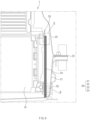
battery pack 1 according to a second embodiment of the present invention includes abattery module 10 and apack housing 20, as illustrated inFIG. 9 . Thepack housing 20 includes alower case 21, anupper case 22, agasket 23, and an insulatingmember 24. - Here, an
elastic member 26 is attached to a surface of the insulatingmember 24 facing thegasket 23 to maintain an outer shape of the insulatingmember 24. - That is, the
elastic member 26 may maintain the outer appearance of the insulatingmember 24, and thus, even if the insulatingmember 24 is deformed, the insulatingmember 24 may be restored to its original shape, and as a result, thegasket 23 may be stably protected against the flame and the gas, which are generated during the thermal runaway of thebattery module 10. - Particularly, the
elastic member 26 has heat resistance and is attached to the entire surface of the insulatingmember 24. Thus, theelastic member 26 may reinforce strength of the entire insulatingmember 24 and restore the entire insulatingmember 24 to its original shape. - The material of the
elastic member 26 may be polypropylene. - Therefore, the
battery pack 1 according to the second embodiment of the present invention may include anelastic member 26 to maintain an external shape of the insulatingmember 24. -
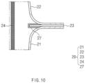
FIG. 10 is a cross-sectional view of a battery pack according to a third embodiment of the present invention. - A
battery pack 1 according to a third embodiment of the present invention includes abattery module 10 and apack housing 20, as illustrated inFIG. 10 . Thepack housing 20 includes alower case 21, anupper case 22, agasket 23, and an insulatingmember 24. - Here, an insulating
layer 27 is applied on an end of thegasket 23 disposed inside thepack housing 20. Thus, the insulatinglayer 27 may protect thegasket 23 from flames and a gas, which are generated during thermal runaway of thebattery module 10. - The insulating
layer 27 may be made of the same material as the insulatingmember 24. - Thus, the
battery pack 1 according to the third embodiment of the present invention includes the insulatinglayer 27 to primarily block the flame and the gas, which are generated during the thermal runaway of thebattery module 10, through the insulatingmember 24 and secondarily block the flame and the gas through the insulatinglayer 27. As a result, thegasket 23 may be greatly prevented from being damaged. -
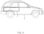
FIG. 11 is a schematic side view of a vehicle according to a fourth embodiment of the present invention. - As illustrated in
FIG. 11 , a vehicle according to a fourth embodiment of the present invention includes abattery pack 1 and avehicle body 2 on which thebattery pack 1 is installed. - Therefore, the safety of the vehicle according to the fourth embodiment of the present invention may be improved by installing the
battery pack 1 including the insulatingmember 24. - Although the battery pack and the vehicle including the same according to the present invention has been described above with reference to the exemplary drawings, various changes and modifications may be made thereto by one skilled in the art without departing from the scope and spirit of the invention as set forth in the appended claims.
-
- 1: Battery pack
- 2: Vehicle body
- 10: Battery module
- 20: Pack housing
- 21: Lower case
- 22: Upper case
- 23: Gasket
- 24: Insulating member
- 25: Adhesive
- 26: Elastic member
- 27: Insulation layer
Claims (14)
- A battery pack comprising:a battery module; anda pack housing configured to accommodate the battery module,wherein the pack housing comprises:a lower case in which the battery module is accommodated;an upper case coupled to cover an upper opening of the lower case;a gasket provided on an interface between the lower case and the upper case; andan insulating member disposed between the battery module and the gasket.
- The battery pack of claim 1, wherein the insulating member is disposed between an end of the battery module, which is disposed in a full-length direction of the battery module, and the gasket.
- The battery pack of claim 2, wherein the insulating member is configured to surround the gasket that is directed toward the end of the battery module.
- The battery pack of claim 2, wherein the insulating member has an area greater than that of the end of the battery module.
- The battery pack of claim 1, wherein one side of the insulating member is attached and fixed to an inner wall of the lower case.
- The battery pack of claim 1, wherein the other side of the insulating member is attached and fixed to an upper end of the battery module.
- The battery pack of claim 1, wherein the insulating member is made of a flexible insulating paper.
- The battery pack of claim 7, wherein the insulating paper is made of mica.
- The battery pack of claim 1, wherein an elastic member configured to maintain an outer appearance of the insulating member is attached to a surface of the insulating member that is directed toward the gasket.
- The battery pack of claim 9, wherein the elastic member has heat resistance and is attached to an entire surface of the insulating member.
- The battery pack of claim 1, wherein one end of the insulating member extends up to a bottom surface of the lower case.
- The battery pack of claim 1, wherein an insulating layer is applied on an end of the gasket disposed inside the pack housing.
- The battery pack of claim 12, wherein the insulating layer is made of the same material as the insulating member.
- A vehicle comprising the battery pack of claim 1.
Applications Claiming Priority (2)
| Application Number | Priority Date | Filing Date | Title |
|---|---|---|---|
| KR1020220129123A KR20240049051A (en) | 2022-10-07 | 2022-10-07 | Battery pack and Vehicle comprising the same |
| PCT/KR2023/014702 WO2024076075A1 (en) | 2022-10-07 | 2023-09-25 | Battery pack and vehicle comprising same |
Publications (2)
| Publication Number | Publication Date |
|---|---|
| EP4576361A1 true EP4576361A1 (en) | 2025-06-25 |
| EP4576361A4 EP4576361A4 (en) | 2026-05-13 |
Family
ID=90608742
Family Applications (1)
| Application Number | Title | Priority Date | Filing Date |
|---|---|---|---|
| EP23875141.6A Pending EP4576361A4 (en) | 2022-10-07 | 2023-09-25 | BATTERY PACK AND VEHICLE WITH IT |
Country Status (6)
| Country | Link |
|---|---|
| US (1) | US20260100449A1 (en) |
| EP (1) | EP4576361A4 (en) |
| JP (1) | JP2025532180A (en) |
| KR (1) | KR20240049051A (en) |
| CN (1) | CN119948685A (en) |
| WO (1) | WO2024076075A1 (en) |
Families Citing this family (1)
| Publication number | Priority date | Publication date | Assignee | Title |
|---|---|---|---|---|
| KR102824776B1 (en) * | 2024-11-08 | 2025-06-27 | 서진산업 주식회사 | Rainf integrated battery case top plate assembly structure |
Family Cites Families (16)
| Publication number | Priority date | Publication date | Assignee | Title |
|---|---|---|---|---|
| US7222406B2 (en) * | 2002-04-26 | 2007-05-29 | Battelle Memorial Institute | Methods for making a multi-layer seal for electrochemical devices |
| KR101902445B1 (en) * | 2014-01-20 | 2018-09-28 | 주식회사 엘지화학 | Battery Pack Having Means for Preventing Permeation of Moisture |
| KR102066911B1 (en) | 2015-12-04 | 2020-01-16 | 주식회사 엘지화학 | Pack Housing Having gasket Member and Battery Pack Containing the Same |
| JP7074455B2 (en) * | 2017-10-31 | 2022-05-24 | イビデン株式会社 | Insulation sheet for assembled battery and assembled battery |
| CN208368577U (en) * | 2018-06-22 | 2019-01-11 | 广东亿鑫丰智能装备股份有限公司 | High-efficiency temperature-controlled power battery box |
| CN112714976A (en) * | 2018-09-07 | 2021-04-27 | 3M创新有限公司 | Fire-protecting articles and related methods |
| JP2020057563A (en) * | 2018-10-04 | 2020-04-09 | 三菱自動車工業株式会社 | Electric vehicle battery pack |
| KR102814166B1 (en) * | 2019-12-05 | 2025-05-28 | 주식회사 엘지에너지솔루션 | Battery pack comprising thermal progagation blocking member |
| CN213278257U (en) * | 2020-09-08 | 2021-05-25 | 江铃汽车股份有限公司 | Battery package and car |
| CN213685713U (en) * | 2020-09-22 | 2021-07-13 | 利拓密封绝缘技术(上海)有限公司 | Fireproof insulating sealing gasket |
| KR102948484B1 (en) * | 2020-09-24 | 2026-04-03 | 현대자동차 주식회사 | Apparatus of insulating battery for electric vehicle |
| JPWO2022085681A1 (en) * | 2020-10-20 | 2022-04-28 | ||
| CN214124021U (en) * | 2020-12-18 | 2021-09-03 | 比亚迪股份有限公司 | Battery pack and vehicle |
| CN113904056A (en) * | 2021-11-12 | 2022-01-07 | 浙江杉盛模塑科技有限公司 | Novel all-weather electric vehicle battery pack shell |
| CN217280991U (en) * | 2021-12-20 | 2022-08-23 | 奥动新能源汽车科技有限公司 | Box body assembly of battery pack and battery pack assembly comprising same |
| CN217444492U (en) * | 2022-02-23 | 2022-09-16 | 苏州新中能源科技有限公司 | Battery box capable of effectively preventing thermal runaway diffusion |
-
2022
- 2022-10-07 KR KR1020220129123A patent/KR20240049051A/en active Pending
-
2023
- 2023-09-25 JP JP2025517650A patent/JP2025532180A/en active Pending
- 2023-09-25 WO PCT/KR2023/014702 patent/WO2024076075A1/en not_active Ceased
- 2023-09-25 EP EP23875141.6A patent/EP4576361A4/en active Pending
- 2023-09-25 CN CN202380068594.7A patent/CN119948685A/en active Pending
- 2023-09-25 US US19/115,147 patent/US20260100449A1/en active Pending
Also Published As
| Publication number | Publication date |
|---|---|
| JP2025532180A (en) | 2025-09-29 |
| US20260100449A1 (en) | 2026-04-09 |
| WO2024076075A1 (en) | 2024-04-11 |
| CN119948685A (en) | 2025-05-06 |
| KR20240049051A (en) | 2024-04-16 |
| EP4576361A4 (en) | 2026-05-13 |
Similar Documents
| Publication | Publication Date | Title |
|---|---|---|
| JP5952418B2 (en) | Battery pack with improved safety | |
| US10476068B2 (en) | Battery module including probe for detecting expansion of battery cell | |
| EP4250457A1 (en) | Battery module and battery pack including same | |
| EP4246707A1 (en) | Battery module and battery pack including same | |
| WO2013111960A1 (en) | Battery module having enhanced safety and battery pack comprising same | |
| WO2009157676A2 (en) | Middle or large-sized battery pack with improved safety | |
| WO2013015524A1 (en) | Battery pack having improved safety | |
| EP4300662A2 (en) | Battery module | |
| CN220086300U (en) | Battery module and battery pack including the same | |
| KR20160144325A (en) | Electrode lead and secondary battery including the same | |
| US20260100449A1 (en) | Battery pack and vehicle including the same | |
| EP4376166A1 (en) | Temperature sensing member, and battery module and battery pack including same | |
| EP4243194B1 (en) | Pouch-shaped battery cell with improved thermal stability | |
| JP7804785B2 (en) | Batteries, battery packs containing the same, and automobiles | |
| KR102712004B1 (en) | Battery cell, battery module, battery pack and vehicle including the same | |
| KR20240085624A (en) | Battery pack | |
| EP4738554A1 (en) | Cap assembly and battery cell comprising the same | |
| EP4614669A1 (en) | Battery module and battery pack including same | |
| WO2012169793A2 (en) | Battery pack safety device | |
| EP4618253A1 (en) | Battery pack having ignition delay structure | |
| KR20260043853A (en) | Battery module and battery pack comprising the same | |
| KR101230868B1 (en) | Large or middle sized battery pack of improved safety at opening | |
| CN117223161A (en) | Battery module with enhanced safety | |
| KR20250067716A (en) | Battery pack and device including the same |
Legal Events
| Date | Code | Title | Description |
|---|---|---|---|
| STAA | Information on the status of an ep patent application or granted ep patent |
Free format text: STATUS: THE INTERNATIONAL PUBLICATION HAS BEEN MADE |
|
| PUAI | Public reference made under article 153(3) epc to a published international application that has entered the european phase |
Free format text: ORIGINAL CODE: 0009012 |
|
| STAA | Information on the status of an ep patent application or granted ep patent |
Free format text: STATUS: REQUEST FOR EXAMINATION WAS MADE |
|
| 17P | Request for examination filed |
Effective date: 20250319 |
|
| AK | Designated contracting states |
Kind code of ref document: A1 Designated state(s): AL AT BE BG CH CY CZ DE DK EE ES FI FR GB GR HR HU IE IS IT LI LT LU LV MC ME MK MT NL NO PL PT RO RS SE SI SK SM TR |
|
| REG | Reference to a national code |
Ref country code: DE Ref legal event code: R079 Free format text: PREVIOUS MAIN CLASS: H01M0050240000 Ipc: H01M0010658000 |
|
| RIC1 | Information provided on ipc code assigned before grant |
Ipc: H01M 10/658 20140101AFI20251203BHEP Ipc: H01M 50/24 20210101ALI20251203BHEP Ipc: H01M 50/59 20210101ALI20251203BHEP Ipc: H01M 50/204 20210101ALI20251203BHEP Ipc: H01M 50/249 20210101ALI20251203BHEP Ipc: B60L 3/00 20190101ALI20251203BHEP Ipc: B60L 50/64 20190101ALI20251203BHEP Ipc: B60L 50/60 20190101ALI20251203BHEP Ipc: B60L 58/21 20190101ALI20251203BHEP Ipc: H01M 50/244 20210101ALI20251203BHEP |
|
| DAV | Request for validation of the european patent (deleted) | ||
| DAX | Request for extension of the european patent (deleted) | ||
| A4 | Supplementary search report drawn up and despatched |
Effective date: 20260414 |
|
| RIC1 | Information provided on ipc code assigned before grant |
Ipc: H01M 10/658 20140101AFI20260408BHEP Ipc: H01M 50/24 20210101ALI20260408BHEP Ipc: H01M 50/59 20210101ALI20260408BHEP Ipc: H01M 50/204 20210101ALI20260408BHEP Ipc: H01M 50/249 20210101ALI20260408BHEP Ipc: B60L 3/00 20190101ALI20260408BHEP Ipc: B60L 50/64 20190101ALI20260408BHEP Ipc: B60L 50/60 20190101ALI20260408BHEP Ipc: B60L 58/21 20190101ALI20260408BHEP Ipc: H01M 50/244 20210101ALI20260408BHEP |