EP4576346A1 - Battery and battery module - Google Patents
Battery and battery module Download PDFInfo
- Publication number
- EP4576346A1 EP4576346A1 EP24207245.2A EP24207245A EP4576346A1 EP 4576346 A1 EP4576346 A1 EP 4576346A1 EP 24207245 A EP24207245 A EP 24207245A EP 4576346 A1 EP4576346 A1 EP 4576346A1
- Authority
- EP
- European Patent Office
- Prior art keywords
- groove
- battery
- wall
- region
- main body
- Prior art date
- Legal status (The legal status is an assumption and is not a legal conclusion. Google has not performed a legal analysis and makes no representation as to the accuracy of the status listed.)
- Pending
Links
Images




Classifications
-
- H—ELECTRICITY
- H01—ELECTRIC ELEMENTS
- H01M—PROCESSES OR MEANS, e.g. BATTERIES, FOR THE DIRECT CONVERSION OF CHEMICAL ENERGY INTO ELECTRICAL ENERGY
- H01M50/00—Constructional details or processes of manufacture of the non-active parts of electrochemical cells other than fuel cells, e.g. hybrid cells
- H01M50/10—Primary casings; Jackets or wrappings
- H01M50/14—Primary casings; Jackets or wrappings for protecting against damage caused by external factors
- H01M50/143—Fireproof; Explosion-proof
-
- H—ELECTRICITY
- H01—ELECTRIC ELEMENTS
- H01M—PROCESSES OR MEANS, e.g. BATTERIES, FOR THE DIRECT CONVERSION OF CHEMICAL ENERGY INTO ELECTRICAL ENERGY
- H01M50/00—Constructional details or processes of manufacture of the non-active parts of electrochemical cells other than fuel cells, e.g. hybrid cells
- H01M50/10—Primary casings; Jackets or wrappings
- H01M50/102—Primary casings; Jackets or wrappings characterised by their shape or physical structure
- H01M50/103—Primary casings; Jackets or wrappings characterised by their shape or physical structure prismatic or rectangular
-
- H—ELECTRICITY
- H01—ELECTRIC ELEMENTS
- H01M—PROCESSES OR MEANS, e.g. BATTERIES, FOR THE DIRECT CONVERSION OF CHEMICAL ENERGY INTO ELECTRICAL ENERGY
- H01M50/00—Constructional details or processes of manufacture of the non-active parts of electrochemical cells other than fuel cells, e.g. hybrid cells
- H01M50/10—Primary casings; Jackets or wrappings
- H01M50/102—Primary casings; Jackets or wrappings characterised by their shape or physical structure
- H01M50/107—Primary casings; Jackets or wrappings characterised by their shape or physical structure having curved cross-section, e.g. round or elliptic
-
- H—ELECTRICITY
- H01—ELECTRIC ELEMENTS
- H01M—PROCESSES OR MEANS, e.g. BATTERIES, FOR THE DIRECT CONVERSION OF CHEMICAL ENERGY INTO ELECTRICAL ENERGY
- H01M50/00—Constructional details or processes of manufacture of the non-active parts of electrochemical cells other than fuel cells, e.g. hybrid cells
- H01M50/10—Primary casings; Jackets or wrappings
- H01M50/147—Lids or covers
- H01M50/148—Lids or covers characterised by their shape
- H01M50/15—Lids or covers characterised by their shape for prismatic or rectangular cells
-
- H—ELECTRICITY
- H01—ELECTRIC ELEMENTS
- H01M—PROCESSES OR MEANS, e.g. BATTERIES, FOR THE DIRECT CONVERSION OF CHEMICAL ENERGY INTO ELECTRICAL ENERGY
- H01M50/00—Constructional details or processes of manufacture of the non-active parts of electrochemical cells other than fuel cells, e.g. hybrid cells
- H01M50/10—Primary casings; Jackets or wrappings
- H01M50/147—Lids or covers
- H01M50/148—Lids or covers characterised by their shape
- H01M50/152—Lids or covers characterised by their shape for cells having curved cross-section, e.g. round or elliptic
-
- H—ELECTRICITY
- H01—ELECTRIC ELEMENTS
- H01M—PROCESSES OR MEANS, e.g. BATTERIES, FOR THE DIRECT CONVERSION OF CHEMICAL ENERGY INTO ELECTRICAL ENERGY
- H01M50/00—Constructional details or processes of manufacture of the non-active parts of electrochemical cells other than fuel cells, e.g. hybrid cells
- H01M50/10—Primary casings; Jackets or wrappings
- H01M50/183—Sealing members
- H01M50/184—Sealing members characterised by their shape or structure
-
- H—ELECTRICITY
- H01—ELECTRIC ELEMENTS
- H01M—PROCESSES OR MEANS, e.g. BATTERIES, FOR THE DIRECT CONVERSION OF CHEMICAL ENERGY INTO ELECTRICAL ENERGY
- H01M50/00—Constructional details or processes of manufacture of the non-active parts of electrochemical cells other than fuel cells, e.g. hybrid cells
- H01M50/10—Primary casings; Jackets or wrappings
- H01M50/183—Sealing members
- H01M50/186—Sealing members characterised by the disposition of the sealing members
-
- H—ELECTRICITY
- H01—ELECTRIC ELEMENTS
- H01M—PROCESSES OR MEANS, e.g. BATTERIES, FOR THE DIRECT CONVERSION OF CHEMICAL ENERGY INTO ELECTRICAL ENERGY
- H01M50/00—Constructional details or processes of manufacture of the non-active parts of electrochemical cells other than fuel cells, e.g. hybrid cells
- H01M50/20—Mountings; Secondary casings or frames; Racks, modules or packs; Suspension devices; Shock absorbers; Transport or carrying devices; Holders
- H01M50/204—Racks, modules or packs for multiple batteries or multiple cells
- H01M50/207—Racks, modules or packs for multiple batteries or multiple cells characterised by their shape
- H01M50/213—Racks, modules or packs for multiple batteries or multiple cells characterised by their shape adapted for cells having curved cross-section, e.g. round or elliptic
-
- H—ELECTRICITY
- H01—ELECTRIC ELEMENTS
- H01M—PROCESSES OR MEANS, e.g. BATTERIES, FOR THE DIRECT CONVERSION OF CHEMICAL ENERGY INTO ELECTRICAL ENERGY
- H01M50/00—Constructional details or processes of manufacture of the non-active parts of electrochemical cells other than fuel cells, e.g. hybrid cells
- H01M50/30—Arrangements for facilitating escape of gases
- H01M50/342—Non-re-sealable arrangements
- H01M50/3425—Non-re-sealable arrangements in the form of rupturable membranes or weakened parts, e.g. pierced with the aid of a sharp member
-
- H—ELECTRICITY
- H01—ELECTRIC ELEMENTS
- H01M—PROCESSES OR MEANS, e.g. BATTERIES, FOR THE DIRECT CONVERSION OF CHEMICAL ENERGY INTO ELECTRICAL ENERGY
- H01M2200/00—Safety devices for primary or secondary batteries
- H01M2200/20—Pressure-sensitive devices
-
- H—ELECTRICITY
- H01—ELECTRIC ELEMENTS
- H01M—PROCESSES OR MEANS, e.g. BATTERIES, FOR THE DIRECT CONVERSION OF CHEMICAL ENERGY INTO ELECTRICAL ENERGY
- H01M2220/00—Batteries for particular applications
- H01M2220/20—Batteries in motive systems, e.g. vehicle, ship, plane
-
- Y—GENERAL TAGGING OF NEW TECHNOLOGICAL DEVELOPMENTS; GENERAL TAGGING OF CROSS-SECTIONAL TECHNOLOGIES SPANNING OVER SEVERAL SECTIONS OF THE IPC; TECHNICAL SUBJECTS COVERED BY FORMER USPC CROSS-REFERENCE ART COLLECTIONS [XRACs] AND DIGESTS
- Y02—TECHNOLOGIES OR APPLICATIONS FOR MITIGATION OR ADAPTATION AGAINST CLIMATE CHANGE
- Y02E—REDUCTION OF GREENHOUSE GAS [GHG] EMISSIONS, RELATED TO ENERGY GENERATION, TRANSMISSION OR DISTRIBUTION
- Y02E60/00—Enabling technologies; Technologies with a potential or indirect contribution to GHG emissions mitigation
- Y02E60/10—Energy storage using batteries
Definitions
- the disclosure relates to the field of battery, and in particular, to a battery and a battery module.
- an explosion-proof valve is disposed close to the end portion of the battery.
- the high-pressure gas inside the battery will break through the explosion-proof valve to achieve pressure relief, so as to avoid causing safety accidents.
- some embodiments of the disclosure provide a battery, including:
- some embodiments of the disclosure provide a battery module including a plurality of batteries, and each of the plurality of batteries adapts the battery as described above.
- the groove is provided on the end wall of the body, and the groove and the explosion-proof sheet are respectively disposed at two ends of the battery housing in the first direction.
- the battery undergoes thermal runaway and the pressure inside the battery is too high, the battery will collapse at the groove on the end wall and the explosion-proof sheet, and the high-pressure gas inside the battery can be released from both of the end wall and the explosion-proof sheet to outside of the battery, thereby improving the pressure relief performance of the battery during thermal runaway, and reducing the explosion risk of the battery during thermal runaway.
- 1000 battery; 100, battery housing; 1, body; 11, side wall; 12, end wall; 12A, first region; 12B, second region; 1A, first sub-region; 1B, second sub-region; 2, groove; 3, current collecting plate; 200, cap assembly; 4, explosion-proof sheet; 5, notch; 121, first surface; 122, second surface; 21, first groove wall; 22, second groove wall; 23, third groove wall; 2A, first side; 2B, second side; 6, cap main body; 11A, main body portion; 12C, port portion; 2C, end surface; 3A, sealing member; 31, embedding portion; 32, convex portion; 6, cap main body; 5A, cavity; 6A, sealing region; and 41A, pressure-bearing surface.
- the groove 2 is in an arc shape on the second surface 122, an angle on the second surface 122 between two connecting lines connecting two ends of the groove 2 and a circle center of a circle where the arc shape of the groove 2 is located is defined as ⁇ , and ⁇ satisfies the following relationship: 0° ⁇ ⁇ ⁇ 22°.
- the angle ⁇ between two connecting lines connecting two ends of the notch 5 and the circle center of the circle where the arc shape of the notch 5 is located, and the angle ⁇ between two connecting lines connecting two ends of the groove 2 and the circle center of the circle where the arc shape of the groove 2 is located are both in the range of 0° to 22°, which can improve the consistency of pressure relief at two ends of the battery 1000 in the first direction X, thereby enhancing the uniform exhaust and pressure relief effects of the battery 1000.
- ⁇ is in the range of 18° to 22°, that is, ⁇ satisfies the following relationship: 18° ⁇ ⁇ ⁇ 22°; and ⁇ is in the range of 0° to 22°, that is, ⁇ satisfies the following relationship: 0° ⁇ ⁇ ⁇ 22°.
- the end wall 12 includes a first region 12A and a second region 12B, and the second region 12B is configured to be welded with a current collecting plate 3. At least part of the groove 2 is disposed in the first region 12A.
- a thickness of part of the end wall 12 provided with the groove 2 in the first direction X is smaller than a thickness of the end wall 12 without the groove 2, and the current collecting plate 3 needs to be welded to the end wall 12 during the assembly and forming of the battery 1000, in order to avoid the thinner thickness of the end wall 12 at the groove 2 in the first direction X affecting the welding of the current collecting plate 3, and to avoid welding through the end wall 12 where the groove 2 is provided when welding the current collecting plate 3 and the end wall 12, in the embodiments, at least part of the groove 2 is misaligned with the welding position of the current collecting plate 3 and the end wall 12. For this, at least part of the groove 2 is disposed in the first region 12A, and the welding region of the current collecting plate 3 and the end wall 12 is disposed in the second region 12B.
- the current collecting plate 3 is welded to part of the end wall 12 in the second region 12B. Therefore, part of the groove 2 can be disposed in a region of the second region 12B where the current collecting plate 3 is not welded to the end wall 12. However, because welding position of the current collecting plate 3 in the second region 12B is not fixed, in order to make the groove 2 suitable to the production processes of different welding methods for the current collecting plate 3, in some embodiments of the disclosure, the entirety of the groove 2 is located in the first region 12A.
- a welding method for welding the current collecting plate 3 and the end wall 12 includes spot welding, wire welding, or the like.
- the welding position of the current collecting plate 3 and the end wall 12 is misaligned with the groove 2.
- the second region 12B includes a first sub-region 1A and a second sub-region 1B, and the first region 12A is located between the first sub-region 1A and the second sub-region 1B.
- the welding region of the current collecting plate 3 and the end wall 12 includes two different regions located on the end wall 12, that is, the first sub-region 1A and the second sub-region 1B. Since the first region 12A is located between the first sub-region 1A and the second sub-region 1B, on the basis of meeting the welding requirement for the end wall 12 and the current collecting plate 3, at least part of the groove 2 is located in the first region 12A, so as to avoid the end wall 12 from being welded through when the current collecting plate 3 is welded to the end wall 12.
- the welding region of the current collecting plate 3 is located only in the first sub-region 1A. In some embodiments, the welding region of the current collecting plate 3 is located only in the second sub-region 1B. In some embodiments, the welding region of the current collecting plate 3 includes both of the first sub-region 1A and the second sub-region 1B.
- the groove 2 can be designed to avoid the first sub-region 1A and the second sub-region 1B, so that the battery housing 100 is suitable to different welding methods for the current collecting plate 3 during the production processes, thereby improving the universality of the battery housing 100.
- the first sub-region 1A is in a circular shape
- the second sub-region 1B is in an annular shape
- the groove 2 is in an arc shape on the second surface 122.
- the groove 2 in a plan view of the end wall 12, includes a first side 2A and a second side 2B oppositely disposed in a radial direction of the circle where the arc shape of the groove 2 is located, and both of the first side 2A and the second side 2B are in an arc shape.
- a diameter of a circle where the arc shape of the first side 2A is located is defined as L1
- a diameter of a circle where the arc shape of the second side 2B is located is defined as L2
- a diameter of the first sub-region 1A is defined as L3
- an inner diameter of the second sub-region 1B is defined as L4, and L1, L2, L3, and L4 satisfy the following relationship: L3 ⁇ 1 2 L1 + L2 ⁇ L4 .
- the first sub-region 1A is in a circular shape
- the second sub-region 1B is in an annular shape
- the groove 2 is in an arc shape on the second surface 122, that is, the diameter of the circle where the arc shape of the groove 2 is located is between the diameter L3 of the first sub-region 1A and the inner diameter L4 of the second sub-region 1B, which can avoid the interference of the groove 2 on the welding of the current collecting plate 3 and the end wall 12.
- 1 2 L1 + L2 is half of the shortest linear distance between the first side 2A and the second side 2B in the radial direction of the circle where the arc shape of the groove 2 is located, so that the groove 2 on the end wall 12 does not interfere with the welding of the end wall 12 and the current collecting plate 3, which is in the second region 12B including the first sub-region 1A and the second sub-region 1B.
- L3 and L4 satisfy the following relationship: 2 mm ⁇ L3 ⁇ 6 mm, and L4 ⁇ 12 mm. That is, a size range of L3 is the welding range between the current collecting plate 3 and the end wall 12 in the first sub-region 1A, and a size range of L4 is the welding range between the current collecting plate 3 and the end wall 12 in the second sub-region 1B.
- an outer diameter of the second sub-region 1B is defined as L5, and L5 satisfies the following relationship: L5 ⁇ 15 mm. That is, the size range of 12mm to 15mm is the welding range between the current collecting plate 3 and the end wall 12 in the second sub-region 1B.
- L1 and L2 satisfy the following relationship: 6 mm ⁇ 1 2 L1 + L2 ⁇ 12 mm , so that at least part of the groove 2 is located in the first region 12A, avoiding the interference of the groove 2 on the welding of the current collecting plate 3 and the end wall 12 in the first sub-region 1A and the second sub-region 1B.
- L1 and L2 satisfy the following relationship: 8 mm ⁇ 1 2 L1 + L2 ⁇ 10 mm , so that the entirety of the groove 2 is located in the first region 12A, and the groove 2 does not interfere with the welding of the end wall 12 and the current collecting plate 3 in the first sub-region 1A and/or the second sub-region 1B.
- a vertical distance from the first surface 121 to the second surface 122 of the end wall 12 in the first direction X is defined as H, and H satisfies the following relationship: 0.3 mm ⁇ H ⁇ 0.8 mm, so that the strength of the battery housing 100 meets general requirements for a battery.
- H a vertical distance from the first surface 121 to the second surface 122 of the end wall 12 in the first direction X
- H satisfies the following relationship: 0.3 mm ⁇ H ⁇ 0.8 mm
- the end wall 12 is in a circular shape.
- a diameter of the end wall 12 is defined as L6, and L6 satisfies the following relationship: 18.10 mm ⁇ L6 ⁇ 21.40 mm.
- size definitions for D, R, ⁇ , ⁇ , L1, and L2 of the groove 2 on the end wall 12 can be applied to a product using the battery 1000, which includes the battery housing 100 having the end wall 12 with the diameter of 18.10 mm to 21.40 mm, so as to avoid the explosion of the product using the battery 1000 during thermal runaway.
- a material of the battery housing 100 is steel.
- Table 1 D (unit: mm) ⁇ (unit: °) Pressure inside the battery housing when the battery collapses at the end wall (unit: MPa)
- Example 1 0.033 58.91 2.215
- Example 2 0.033 55.92 2.187
- Example 3 0.036 61.56 2.232
- Example 4 0.039 57.06 2.172
- Example 5 0.039 56.47 2.437
- Example 6 0.04 54.83 2.32
- Example 7 0.041 51.83 1.967
- Example 8 0.042 56.03 2.472
- Example 9 0.043 57.3 1.972
- Example 10 0.046 55.96 2.395
- Example 11 0.048 54.27 2.28
- Example 12 0.048 55.59 2.065
- Example 13 0.051 54.41 2.415
- Example 14 0.052 54.25 3.002
- Example 15 0.06 55.67 2.897
- Example 16 0.064 57.46 3.124
- Example 17 0.065 52.45 2.895
- the groove 2 on the end wall 12 in the examples meets the design requirements for pressure relief by collapsing when the pressure at the end wall 12 is in a range of 1.90 MPa to 3.15 MPa. That is, when the pressure of the gas inside the battery 1000 was in the range of 1.90 MPa to 3.15 MPa, the battery 1000 collapsed at the end wall 12. Based on the above, pressure at two ends of the battery 1000 was released at the end wall 12 and the explosion-proof sheet 4 simultaneously, thereby avoiding the explosion of the battery housing 100, and improving the pressure relief performance of the battery 1000.
- the side wall 11 includes a main body portion 11A in a cylindrical shape and a port portion 12C connected to the main body portion 11A.
- the port portion 12C includes an end surface 2C away from the main body portion 11A.
- the cap assembly 200 includes the sealing member 3A, and the sealing member 3A includes an embedding portion 31 and a convex portion 32.
- the embedding portion 31 is formed by bending the port portion 12C towards an inner wall of the main body portion 11A to press the sealing member 3A. At least part of the end surface 2C is embedded into the embedding portion 31.
- the convex portion 32 is connected to the embedding portion 31, and the convex portion 32 covers a region of the end surface 2C not embedded into the embedding portion 31.
- the embedding portion 31 and the convex portion 32 cover and protect the end surface 2C of the port portion 12C without coating protection, avoiding the direct contact between the end surface 2C and air, thereby reducing the rusting risk at the end surface 2C.
- the sealing member 3A and other components of the battery 1000 can be supported by the bent port portion 12C.
- the sealing member 3A has a certain elastic deformation performance, and thus, when the port portion 12C presses the embedding portion 31, part of the embedding portion 31 close to the end surface 2C will shield part of the end surface 2C due to its own deformation, so as to shield the end surface 2C in combination with the convex portion 32 disposed on the embedding portion 31.
- the battery 1000 further includes a cap main body 6.
- the cap main body 6 is disposed in a cavity 5A of the main body portion 11A close to the port portion 12C.
- An edge of the cap main body 6 is separated from an inner wall of the main body portion 11A by a sealing region 6A.
- At least part of the sealing member 3A is disposed in the sealing region 6A.
- the sealing member 3A is in interference fit with the edge of the cap main body 6 and the inner wall of the main body portion 11A.
- the sealing member 3A can seal the gap between the cap main body 6 and the main body portion 11A in the sealing region 6A, so as to ensure the sealing performance of the sealing region 6A between the cap main body 6 and the main body portion 11A. Moreover, since the sealing member 3A is in interference fit with part of the cap main body 6 and part of the main body portion 11A, the sealing performance of the sealing region 6A can be further improved.
- the cap main body 6 includes a pressure-bearing surface 41A.
- the port portion 12C is bent towards the inner wall of the main body portion 11A and presses the sealing member 3A.
- the sealing member 3A abuts against the pressure-bearing surface 41A to form the embedding portion 31. Therefore, in the embodiments, part of the sealing member 3A located between the port portion 12C and the pressure-bearing surface 41A of the cap main body 6 is also in interference fit with the port portion 12C and the cap main body 6, so that part of the sealing member 3A located at the end surface 2C deforms to form the embedding portion 31.
- the port portion 12C extends obliquely in a direction close to the cap main body 6, so that a vertical distance from an end of the port portion 12C connected to the main body portion 11A in the second direction Y to the cap main body 6 in the first direction X is greater than a vertical distance from the end surface 2C to the cap main body 6 in the first direction X, thereby ensuring firmness of the fixation and sealing performance among the side wall 11, the cap main body 6, and the sealing member 3A.
- an angle between a plane where the port portion 12C is located and a plane where the cap main body 6 is located is defined as ⁇ , and ⁇ satisfies the following relationship: 4° ⁇ ⁇ ⁇ 20°.
- ⁇ when ⁇ is less than 4°, it may cause poor sealing performance among the side wall 11, the sealing member 3A, and the cap main body 6; and when ⁇ is greater than 20°, the sealing member 3A disposed between the port portion 12C and the cap main body 6 will affect the bending of the port portion 12C, making the bending angle of the port portion 12C not too large. However, when the bending angle of the port portion 12C is too large, the sealing member 3A will be excessively pressed, causing the deformation of the sealing member 3A to exceed its elastic limit, thereby affecting the sealing performance of the side wall 11 and the cap main body 6.
- a length of part of the sealing member 3A located at a side of the pressure-bearing surface 41A in the second direction Y is defined as L7
- a length of the embedding portion 31 in the second direction Y is defined as L8, and L7 and L8 satisfy the following relationship: 0.1L7 ⁇ L8 ⁇ 0.4L7, so that the embedding portion 31 and the convex portion 32 cover the end surface 2C.
- a maximum vertical distance from a side of the convex portion 32 away from the cap main body 6 to the pressure-bearing surface 41A in the first direction X is defined as L9
- a minimum vertical distance from the end surface 2C to the pressure-bearing surface 41A in the first direction X is defined as L10
- L9 and L10 satisfy the following relationship: 0.6L9 ⁇ L10 ⁇ 0.9L9, so that the embedding portion 31 and the convex portion 32 cover the end surface 2C. It can be understood that, when L10 is less than 0.6L9, part of the sealing member 3A may curl up, causing poor appearance of the sealing member 3A.
- the battery 1000 further includes a rust remover disposed on the end surface 2C, so that the rust remover, all of the embedding portion 31 and the convex portion 32 can protect the end surface 2C, thereby enhancing the rust-proof protection to the end surface 2C.
- the rust remover can be a rust-proof oil, a rust-proof paint, a rust-proof adhesive, or the like.
- the rust remover is the rust-proof oil.
- Some embodiments of the disclosure further provide a battery module including a plurality of batteries, each of the batteries adapts the battery 1000 as described in any one of the above-mentioned embodiments. Since the battery module adopts the battery 1000 as described above, it has the beneficial effects brought by the battery 1000 as described in any one of the above-mentioned embodiments, which will not be repeated here.
Landscapes
- Chemical & Material Sciences (AREA)
- Chemical Kinetics & Catalysis (AREA)
- Electrochemistry (AREA)
- General Chemical & Material Sciences (AREA)
- Gas Exhaust Devices For Batteries (AREA)
- Connection Of Batteries Or Terminals (AREA)
- Sealing Battery Cases Or Jackets (AREA)
- Battery Mounting, Suspending (AREA)
Abstract
The disclosure provides a battery (1000) and a battery module. The battery (1000) includes a battery housing (100) and a cap assembly (200); the battery housing (100) includes a body (1), and the body (1) includes a side wall (11) extending in a first direction and an end wall (12) connected to an end of the side wall (11); the end wall (12) includes a first surface (121) and a second surface (122) opposite to each other in the first direction, and the first surface (121) faces an explosion-proof sheet (4) of the cap assembly (200); and the end wall (12) is provided with a groove (2) on the second surface (122), and the groove (2) is recessed from the second surface (122) towards the first surface (121).
Description
- The disclosure relates to the field of battery, and in particular, to a battery and a battery module.
- In related art, in order to release the pressure inside a battery in time during thermal runaway, an explosion-proof valve is disposed close to the end portion of the battery. When the pressure inside the battery is too high, the high-pressure gas inside the battery will break through the explosion-proof valve to achieve pressure relief, so as to avoid causing safety accidents.
- For the situation where the pressure inside the battery increases sharply, when the explosion-proof valve fails to release pressure in time, there may be an explosion risk of a housing of the battery caused by high pressure inside the battery.
- In a first aspect, some embodiments of the disclosure provide a battery, including:
- a battery housing including a body, in which the body includes a side wall extending in a first direction and an end wall connected to an end of the side wall; and
- a cap assembly disposed at an end of the side wall away from the end wall and including an explosion-proof sheet, in which the explosion-proof sheet is disposed facing the end wall;
- in which the end wall includes a first surface and a second surface opposite to each other in the first direction, and the first surface faces the explosion-proof sheet; the end wall is provided with a groove on the second surface, and the groove is recessed from the second surface towards the first surface; and a vertical distance from a deepest point of the groove to the first surface in the first direction is defined as D, and D satisfies the following relationship: 0.03 mm ≤ D ≤ 0.08 mm.
- In a second aspect, some embodiments of the disclosure provide a battery module including a plurality of batteries, and each of the plurality of batteries adapts the battery as described above.
- In the embodiments of the disclosure, the groove is provided on the end wall of the body, and the groove and the explosion-proof sheet are respectively disposed at two ends of the battery housing in the first direction. When the battery undergoes thermal runaway and the pressure inside the battery is too high, the battery will collapse at the groove on the end wall and the explosion-proof sheet, and the high-pressure gas inside the battery can be released from both of the end wall and the explosion-proof sheet to outside of the battery, thereby improving the pressure relief performance of the battery during thermal runaway, and reducing the explosion risk of the battery during thermal runaway.
-
-
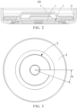
FIG. 1 is a schematic cross-sectional view of a battery provided in some embodiments of the disclosure. -
FIG. 2 is a schematic cross-sectional view of a cap assembly provided in some embodiments of the disclosure. -
FIG. 3 is a schematic structural view of an explosion-proof sheet provided in some embodiments of the disclosure. -
FIG. 4 is a schematic enlarged view at position A inFIG. 1 . -
FIG. 5 is a schematic enlarged view at position B inFIG. 1 . -
FIG. 6 is a schematic structural view of an end wall provided in some embodiments of the disclosure. -
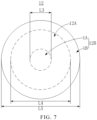
FIG. 7 is another schematic structural view of an end wall provided in some embodiments of the disclosure. -
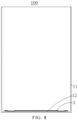
FIG. 8 is a schematic view of a battery housing and a current collecting plate after assembly provided in some embodiments of the disclosure. -
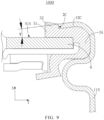
FIG. 9 is a schematic local cross-sectional view of the battery provided in some embodiments of the disclosure. -
FIG. 10 is another schematic local cross-sectional view of the battery provided in some embodiments of the disclosure. -
FIG. 11 is a schematic cross-sectional view of a sealing member provided in some embodiments of the disclosure. -
FIG. 12 is a schematic cross-sectional view of the battery housing and a cap main body after assembly provided in some embodiments of the disclosure. - 1000, battery; 100, battery housing; 1, body; 11, side wall; 12, end wall; 12A, first region; 12B, second region; 1A, first sub-region; 1B, second sub-region; 2, groove; 3, current collecting plate; 200, cap assembly; 4, explosion-proof sheet; 5, notch; 121, first surface; 122, second surface; 21, first groove wall; 22, second groove wall; 23, third groove wall; 2A, first side; 2B, second side; 6, cap main body; 11A, main body portion; 12C, port portion; 2C, end surface; 3A, sealing member; 31, embedding portion; 32, convex portion; 6, cap main body; 5A, cavity; 6A, sealing region; and 41A, pressure-bearing surface.
- In the description of the disclosure, unless otherwise specified or limited, the terms "connected", "connection", and "fixed" should be understood broadly. For example, it can be a fixed connection, a detachable connection, or an integrated unit; alternatively, it can be a mechanical connection or an electrical connection; alternatively, it can be a direct connection or an indirect connection through an intermediate medium; and alternatively, it can be an internal connection of two components or an interaction relationship between two components. For an ordinary person skilled in the art, specific meanings of the above terms in the disclosure can be understood based on specific situations.
- In the disclosure, unless otherwise specified or limited, "a first feature above or below a second feature" may include a direct contact between the first feature and the second feature, or an indirect contact through another feature between the first feature and the second feature, instead of the direct contact. Moreover, the first feature is disposed "on" or "above" the second feature, indicating that the first feature is directly above or diagonally above the second feature, or simply indicating that the first feature is horizontally higher than the second feature. The phrase "the first feature is disposed below or under the second feature" indicates that the first feature is directly below or diagonally below the second feature, or simply indicates that the first feature is horizontally lower than the second feature.
- In the description of the disclosure, directional or positional relationships indicated by the terms "on", "above", "below", "front", "back", "left", "right", and the like, are based on the directional or positional relationships shown in the drawings, which are used only for the convenience of describing the disclosure and simplifying the description, rather than indicating or implying that the devices or elements must have a specific direction, be constructed or operated in a specific direction. Therefore, the terms cannot be interpreted as a limitation on the disclosure. In addition, the terms "first" and "second" are used only for the purpose of description and do not have specific meanings.
- As illustrated in
FIG. 1 ,FIG. 4 ,FIG. 5 , andFIG. 8 , some embodiments of the disclosure provide abattery 1000 including abattery housing 100 and acap assembly 200. Thebattery housing 100 includes a body 1, and the body 1 includes aside wall 11 extending in a first direction X and anend wall 12 connected to an end of theside wall 11. Thecap assembly 200 is disposed at an end of theside wall 11 away from theend wall 12. Thecap assembly 200 includes an explosion-proof sheet 4 disposed facing theend wall 12. Theend wall 12 includes afirst surface 121 and asecond surface 122 disposed opposite to each other in the first direction X, and thefirst surface 121 faces the explosion-proof sheet 4. Theend wall 12 is provided with agroove 2 on thesecond surface 122, and thegroove 2 is recessed from thesecond surface 122 towards thefirst surface 121. A vertical distance from a deepest point of thegroove 2 to thefirst surface 121 in the first direction X is defined as D, and D satisfies the following relationship: 0.03 mm ≤ D ≤ 0.08 mm. - In the embodiments of the disclosure, the
groove 2 is provided on theend wall 12 of the body 1, and thegroove 2 and the explosion-proof sheet 4 are respectively disposed at two ends of thebattery housing 100 in the first direction X. When thebattery 1000 undergoes thermal runaway and the pressure inside thebattery 1000 is too high, thebattery 1000 will collapse at thegroove 2 on theend wall 12 and the explosion-proof sheet 4, and the high-pressure gas inside thebattery 1000 can be released from both of theend wall 12 and the explosion-proof sheet 4 to outside of thebattery 1000, thereby improving the pressure relief performance of thebattery 1000 during thermal runaway, and reducing the explosion risk of thebattery 1000 during thermal runaway. - It can be understood that, when D is less than 0.03 mm, during thermal runaway, there may be a risk of insufficient structural strength at the
end wall 12 of thebattery housing 100. Furthermore, it may occur that the explosion-proof sheet 4 has not collapsed but thegroove 2 has collapsed, causing pressure relief from one end, which may result in the explosion of thebattery housing 100. Moreover, when D is less than 0.03 mm, it is easy to cause cracking of theend wall 12 during processing and forming thegroove 2 on theend wall 12. When D is greater than 0.08 mm, during thermal runaway, thebattery 1000 may collapse at the explosion-proof sheet 4, but thebattery 1000 does not collapse at thegroove 2, and thus, the gas inside thebattery 1000 can be released from the explosion-proof sheet 4, not theend wall 12, which may result in the explosion of thebattery housing 100. - In addition, a vertical distance D from the deepest point of the
groove 2 to thefirst surface 121 in the first direction X is set in a range of 0.03 mm to 0.08 mm, so as to meet design requirements that when the pressure inside thebattery 1000 reaches between 1.90 MPa and 3.15 MPa, thebattery 1000 collapses at both of the explosion-proof sheet 4 and theend wall 12 to release the high-pressure gas inside thebattery 1000. It should be noted that, in some embodiments of the disclosure, when the pressure inside thebattery 1000 reaches between 1.90 MPa and 2.73 MPa, thebattery 1000 may collapse at the explosion-proof sheet 4. Moreover, during thermal runaway, when the pressure inside thebattery 1000 is greater than 2.73 MPa, thebattery 1000 may collapse at the explosion-proof sheet 4 either. For the structural design with thegroove 2 provided on theend wall 12, when D satisfies the following relationship: 0.03 mm ≤ D ≤ 0.08 mm, and the pressure inside thebattery 1000 reaches between 1.90 MPa and 3.15 MPa, thebattery 1000 may collapse at theend wall 12. - In some embodiments of the disclosure, when the pressure inside the
battery 1000 reaches between 2.70 MPa and 3.15 MPa, thebattery 1000 may collapse at theend wall 12. The gas inside thebattery 1000 may be released from the explosion-proof sheet 4 before the pressure reaches between 1.90 MPa and 2.70 MPa, at which thebattery 1000 may not collapse at theend wall 12, so as to avoid theend wall 12 of thebattery housing 100 being damaged and causing danger. When the pressure inside thebattery 1000 is high, that is, between 2.70 MPa and 3.15 MPa, the pressure can be released from the explosion-proof sheet 4 and theend wall 12 together to avoid danger caused by the damage to thebattery housing 100. - As illustrated in
FIG. 2 , in some embodiments of the disclosure, thecap assembly 200 includes asealing member 3A, and the explosion-proof sheet 4 is disposed in a space enclosed by the sealingmember 3A. - As illustrated in
FIG. 5 , in some embodiments of the disclosure, thegroove 2 is in an arc shape on thesecond surface 122, and thegroove 2 includes afirst groove wall 21 and asecond groove wall 22 disposed in a radial direction of a circle where the arc shape of thegroove 2 is located. In a cross-sectional view of thebattery 1000, both of thefirst groove wall 21 and thesecond groove wall 22 are inclined surfaces, and a plane where thefirst groove wall 21 is located intersects with a plane where thesecond groove wall 22 is located. An angle in the first direction X between the plane where thefirst groove wall 21 is located and the plane where thesecond groove wall 22 is located is defined as θ, and θ satisfies the following relationship: 25°≤ θ ≤ 65°. With this setting, on the basis of the same opening size of thegroove 2, an area of a bottom of thegroove 2 can be reduced, and thus a collapse area of thebattery housing 100 at thegroove 2 during pressure relief of thebattery housing 100 can be reduced. - In some embodiments of the disclosure, the
groove 2 further includes athird groove wall 23 connecting thefirst groove wall 21 and thesecond groove wall 22, and the deepest point of thegroove 2 is located on thethird groove wall 23. In the cross-sectional view of thebattery 1000, thethird groove wall 23 is in a circular arc shape, and a circle center of a circle corresponding to the circular arc shape of thethird groove wall 23 is located in thegroove 2. A radius of the circle corresponding to the circular arc shape of thethird groove wall 23 is defined as R, and R satisfies the following relationship: 0.05 mm ≤ R ≤ 0.1 mm. In related art, a head of a stamping die for processing thegroove 2 is designed as a rounded corner. In the embodiments, during stamping of the stamping die, by using the stamping die with the head having a radius of 0.05 mm to 0.1 mm, thethird groove wall 23 with the radius of the circle corresponding to the circular arc shape of thethird groove wall 23 in the range of 0.05 mm to 0.1 mm can be formed. Moreover, the head of the stamping die for processing thegroove 2 is designed as the rounded corner, so as to avoid damage to part of theend wall 12 to be stamped during the stamping process, and also to prevent a groove width of thegroove 2 from being too large after stamping. - As illustrated in
FIG. 2 and FIG. 3 , in some embodiments of the disclosure, the explosion-proof sheet 4 is provided with anotch 5. Thenotch 5 is in an arc shape on the explosion-proof sheet 4, an angle on the explosion-proof sheet 4 between two connecting lines connecting two ends of thenotch 5 and a circle center of a circle where the arc shape of thenotch 5 is located is defined as α, and α satisfies the following relationship: 0° ≤ α ≤ 22°. As illustrated inFIG. 6 , thegroove 2 is in an arc shape on thesecond surface 122, an angle on thesecond surface 122 between two connecting lines connecting two ends of thegroove 2 and a circle center of a circle where the arc shape of thegroove 2 is located is defined as β, and β satisfies the following relationship: 0° ≤ β ≤ 22°. In the embodiments, the angle α between two connecting lines connecting two ends of thenotch 5 and the circle center of the circle where the arc shape of thenotch 5 is located, and the angle β between two connecting lines connecting two ends of thegroove 2 and the circle center of the circle where the arc shape of thegroove 2 is located, are both in the range of 0° to 22°, which can improve the consistency of pressure relief at two ends of thebattery 1000 in the first direction X, thereby enhancing the uniform exhaust and pressure relief effects of thebattery 1000. It can be understood that, when α is a fixed value in the range of 0° to 22°, β can be any value in the range of 0° to 22° to design the size of thegroove 2; and when β is a fixed value in the range of 0° to 22°, α can be any value in the range of 0° to 22° to design the size of thenotch 5. - In some embodiments of the disclosure, α is in the range of 18° to 22°, that is, α satisfies the following relationship: 18° ≤ α ≤ 22°; and β is in the range of 0° to 22°, that is, β satisfies the following relationship: 0° ≤ β ≤ 22°.
- In some embodiments of the disclosure, the
notch 5 and thegroove 2 are disposed facing each other in the first direction X, which can further improve the consistency of the pressure relief at two ends of thebattery 1000 in the first direction X to the high-pressure gas inside thebattery 1000, and avoid the explosion of thebattery housing 100 when thebattery 1000 undergoes thermal runaway and the pressure in thebattery 1000 is released. - As illustrated in
FIG. 7 andFIG. 8 , theend wall 12 includes afirst region 12A and asecond region 12B, and thesecond region 12B is configured to be welded with acurrent collecting plate 3. At least part of thegroove 2 is disposed in thefirst region 12A. Since a thickness of part of theend wall 12 provided with thegroove 2 in the first direction X is smaller than a thickness of theend wall 12 without thegroove 2, and thecurrent collecting plate 3 needs to be welded to theend wall 12 during the assembly and forming of thebattery 1000, in order to avoid the thinner thickness of theend wall 12 at thegroove 2 in the first direction X affecting the welding of thecurrent collecting plate 3, and to avoid welding through theend wall 12 where thegroove 2 is provided when welding thecurrent collecting plate 3 and theend wall 12, in the embodiments, at least part of thegroove 2 is misaligned with the welding position of thecurrent collecting plate 3 and theend wall 12. For this, at least part of thegroove 2 is disposed in thefirst region 12A, and the welding region of thecurrent collecting plate 3 and theend wall 12 is disposed in thesecond region 12B. - It can be understood that the
current collecting plate 3 is welded to part of theend wall 12 in thesecond region 12B. Therefore, part of thegroove 2 can be disposed in a region of thesecond region 12B where thecurrent collecting plate 3 is not welded to theend wall 12. However, because welding position of thecurrent collecting plate 3 in thesecond region 12B is not fixed, in order to make thegroove 2 suitable to the production processes of different welding methods for thecurrent collecting plate 3, in some embodiments of the disclosure, the entirety of thegroove 2 is located in thefirst region 12A. - In addition, a welding method for welding the
current collecting plate 3 and theend wall 12 includes spot welding, wire welding, or the like. In some embodiments, when part of thegroove 2 is located in thesecond region 12B, the welding position of thecurrent collecting plate 3 and theend wall 12 is misaligned with thegroove 2. - In some embodiments of the disclosure, the
second region 12B includes afirst sub-region 1A and asecond sub-region 1B, and thefirst region 12A is located between thefirst sub-region 1A and thesecond sub-region 1B. In the embodiments, the welding region of thecurrent collecting plate 3 and theend wall 12 includes two different regions located on theend wall 12, that is, thefirst sub-region 1A and thesecond sub-region 1B. Since thefirst region 12A is located between thefirst sub-region 1A and thesecond sub-region 1B, on the basis of meeting the welding requirement for theend wall 12 and thecurrent collecting plate 3, at least part of thegroove 2 is located in thefirst region 12A, so as to avoid theend wall 12 from being welded through when thecurrent collecting plate 3 is welded to theend wall 12. - In some embodiments, the welding region of the
current collecting plate 3 is located only in thefirst sub-region 1A. In some embodiments, the welding region of thecurrent collecting plate 3 is located only in thesecond sub-region 1B. In some embodiments, the welding region of thecurrent collecting plate 3 includes both of thefirst sub-region 1A and thesecond sub-region 1B. Thegroove 2 can be designed to avoid thefirst sub-region 1A and thesecond sub-region 1B, so that thebattery housing 100 is suitable to different welding methods for thecurrent collecting plate 3 during the production processes, thereby improving the universality of thebattery housing 100. - In some embodiments of the disclosure, the
first sub-region 1A is in a circular shape, thesecond sub-region 1B is in an annular shape, and thegroove 2 is in an arc shape on thesecond surface 122. As illustrated inFIG. 6 , in a plan view of theend wall 12, thegroove 2 includes afirst side 2A and asecond side 2B oppositely disposed in a radial direction of the circle where the arc shape of thegroove 2 is located, and both of thefirst side 2A and thesecond side 2B are in an arc shape. A diameter of a circle where the arc shape of thefirst side 2A is located is defined as L1, a diameter of a circle where the arc shape of thesecond side 2B is located is defined as L2, a diameter of thefirst sub-region 1A is defined as L3, and an inner diameter of thesecond sub-region 1B is defined as L4, and L1, L2, L3, and L4 satisfy the following relationship:
first sub-region 1A is in a circular shape, thesecond sub-region 1B is in an annular shape, and thegroove 2 is in an arc shape on thesecond surface 122, that is, the diameter of the circle where the arc shape of thegroove 2 is located is between the diameter L3 of thefirst sub-region 1A and the inner diameter L4 of thesecond sub-region 1B, which can avoid the interference of thegroove 2 on the welding of thecurrent collecting plate 3 and theend wall 12. Moreover, since thegroove 2 includes thefirst side 2A and thesecond side 2B oppositely disposed in the radial direction of the circle where the arc shape of thegroove 2 is located,
first side 2A and thesecond side 2B in the radial direction of the circle where the arc shape of thegroove 2 is located, so that thegroove 2 on theend wall 12 does not interfere with the welding of theend wall 12 and thecurrent collecting plate 3, which is in thesecond region 12B including thefirst sub-region 1A and thesecond sub-region 1B. - In some embodiments of the disclosure, L3 and L4 satisfy the following relationship: 2 mm ≤ L3 ≤ 6 mm, and L4 ≥ 12 mm. That is, a size range of L3 is the welding range between the
current collecting plate 3 and theend wall 12 in thefirst sub-region 1A, and a size range of L4 is the welding range between thecurrent collecting plate 3 and theend wall 12 in thesecond sub-region 1B. In some embodiments, an outer diameter of thesecond sub-region 1B is defined as L5, and L5 satisfies the following relationship: L5 ≤ 15 mm. That is, the size range of 12mm to 15mm is the welding range between thecurrent collecting plate 3 and theend wall 12 in thesecond sub-region 1B. In some embodiments of the disclosure, L1 and L2 satisfy the following relationship:
groove 2 is located in thefirst region 12A, avoiding the interference of thegroove 2 on the welding of thecurrent collecting plate 3 and theend wall 12 in thefirst sub-region 1A and thesecond sub-region 1B. - In some embodiments of the disclosure, L1 and L2 satisfy the following relationship:

groove 2 is located in thefirst region 12A, and thegroove 2 does not interfere with the welding of theend wall 12 and thecurrent collecting plate 3 in thefirst sub-region 1A and/or thesecond sub-region 1B. - As illustrated in
FIG. 4 , in some embodiments of the disclosure, a vertical distance from thefirst surface 121 to thesecond surface 122 of theend wall 12 in the first direction X is defined as H, and H satisfies the following relationship: 0.3 mm ≤ H ≤ 0.8 mm, so that the strength of thebattery housing 100 meets general requirements for a battery. In can be understood that, when H is less than 0.3 mm, it may cause insufficient strength of thebattery housing 100; and when H is greater than 0.8 mm, the overall thickness of theend wall 12 in the first direction X may be too thick, making it difficult for thebattery 1000 to collapse at theend wall 12 and release the high-pressure gas inside thebattery 1000. - As illustrated in
FIG. 4 , in some embodiments of the disclosure, theend wall 12 is in a circular shape. A diameter of theend wall 12 is defined as L6, and L6 satisfies the following relationship: 18.10 mm ≤ L6 ≤ 21.40 mm. In the embodiments of the disclosure, size definitions for D, R, θ, β, L1, and L2 of thegroove 2 on theend wall 12 can be applied to a product using thebattery 1000, which includes thebattery housing 100 having theend wall 12 with the diameter of 18.10 mm to 21.40 mm, so as to avoid the explosion of the product using thebattery 1000 during thermal runaway. In some embodiments of the disclosure, a material of thebattery housing 100 is steel. - Referring to Table 1, the technical solutions and technical effects of the disclosure are described in detail according to the following examples.
Table 1 D (unit: mm) θ (unit: °) Pressure inside the battery housing when the battery collapses at the end wall (unit: MPa) Example 1 0.033 58.91 2.215 Example 2 0.033 55.92 2.187 Example 3 0.036 61.56 2.232 Example 4 0.039 57.06 2.172 Example 5 0.039 56.47 2.437 Example 6 0.04 54.83 2.32 Example 7 0.041 51.83 1.967 Example 8 0.042 56.03 2.472 Example 9 0.043 57.3 1.972 Example 10 0.046 55.96 2.395 Example 11 0.048 54.27 2.28 Example 12 0.048 55.59 2.065 Example 13 0.051 54.41 2.415 Example 14 0.052 54.25 3.002 Example 15 0.06 55.67 2.897 Example 16 0.064 57.46 3.124 Example 17 0.065 52.45 2.895 Example 18 0.066 51.16 2.87 Example 19 0.069 55.61 2.963 Example 20 0.07 54.91 3.112 Example 21 0.07 54.29 2.937 Example 22 0.074 53.91 3.111 Example 23 0.079 52.1 3.002 - It can be seen from Table 1 that when D satisfies the following relationship: 0.03 mm ≤ D ≤ 0.08 mm, and θ satisfies the following relationship: 25° ≤θ ≤ 65°, the
groove 2 on theend wall 12 in the examples meets the design requirements for pressure relief by collapsing when the pressure at theend wall 12 is in a range of 1.90 MPa to 3.15 MPa. That is, when the pressure of the gas inside thebattery 1000 was in the range of 1.90 MPa to 3.15 MPa, thebattery 1000 collapsed at theend wall 12. Based on the above, pressure at two ends of thebattery 1000 was released at theend wall 12 and the explosion-proof sheet 4 simultaneously, thereby avoiding the explosion of thebattery housing 100, and improving the pressure relief performance of thebattery 1000. - As illustrated in
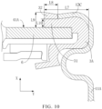
FIG. 9 ,FIG. 10 , andFIG. 11 , in some embodiments, theside wall 11 includes amain body portion 11A in a cylindrical shape and aport portion 12C connected to themain body portion 11A. Theport portion 12C includes anend surface 2C away from themain body portion 11A. Thecap assembly 200 includes the sealingmember 3A, and the sealingmember 3A includes an embeddingportion 31 and aconvex portion 32. The embeddingportion 31 is formed by bending theport portion 12C towards an inner wall of themain body portion 11A to press the sealingmember 3A. At least part of theend surface 2C is embedded into the embeddingportion 31. Theconvex portion 32 is connected to the embeddingportion 31, and theconvex portion 32 covers a region of theend surface 2C not embedded into the embeddingportion 31. - In the embodiments of the disclosure, the embedding
portion 31 and theconvex portion 32 cover and protect theend surface 2C of theport portion 12C without coating protection, avoiding the direct contact between theend surface 2C and air, thereby reducing the rusting risk at theend surface 2C. - It can be understood that, when the
side wall 11 of thebattery 1000 is bent, that is, when theport portion 12C is bent, the sealingmember 3A and other components of thebattery 1000 can be supported by thebent port portion 12C. In some embodiments of the disclosure, the sealingmember 3A has a certain elastic deformation performance, and thus, when theport portion 12C presses the embeddingportion 31, part of the embeddingportion 31 close to theend surface 2C will shield part of theend surface 2C due to its own deformation, so as to shield theend surface 2C in combination with theconvex portion 32 disposed on the embeddingportion 31. - As illustrated in
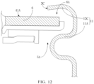
FIG. 9 ,FIG. 10 , andFIG. 12 , in some embodiments of the disclosure, thebattery 1000 further includes a capmain body 6. The capmain body 6 is disposed in acavity 5A of themain body portion 11A close to theport portion 12C. An edge of the capmain body 6 is separated from an inner wall of themain body portion 11A by a sealingregion 6A. At least part of the sealingmember 3A is disposed in thesealing region 6A. The sealingmember 3A is in interference fit with the edge of the capmain body 6 and the inner wall of themain body portion 11A. Therefore, in the embodiments, the sealingmember 3A can seal the gap between the capmain body 6 and themain body portion 11A in thesealing region 6A, so as to ensure the sealing performance of the sealingregion 6A between the capmain body 6 and themain body portion 11A. Moreover, since the sealingmember 3A is in interference fit with part of the capmain body 6 and part of themain body portion 11A, the sealing performance of the sealingregion 6A can be further improved. - In some embodiments of the disclosure, the cap
main body 6 includes a pressure-bearingsurface 41A. Theport portion 12C is bent towards the inner wall of themain body portion 11A and presses the sealingmember 3A. The sealingmember 3A abuts against the pressure-bearingsurface 41A to form the embeddingportion 31. Therefore, in the embodiments, part of the sealingmember 3A located between theport portion 12C and the pressure-bearingsurface 41A of the capmain body 6 is also in interference fit with theport portion 12C and the capmain body 6, so that part of the sealingmember 3A located at theend surface 2C deforms to form the embeddingportion 31. - As illustrated in
FIG. 9 ,FIG. 11 , andFIG. 12 , in some embodiments of the disclosure, theport portion 12C extends obliquely in a direction close to the capmain body 6, so that a vertical distance from an end of theport portion 12C connected to themain body portion 11A in the second direction Y to the capmain body 6 in the first direction X is greater than a vertical distance from theend surface 2C to the capmain body 6 in the first direction X, thereby ensuring firmness of the fixation and sealing performance among theside wall 11, the capmain body 6, and the sealingmember 3A. - As illustrated in
FIG. 9 , in some embodiments of the disclosure, an angle between a plane where theport portion 12C is located and a plane where the capmain body 6 is located is defined as γ, and γ satisfies the following relationship: 4° ≤ γ ≤ 20°. With this setting, when theport portion 12C presses the sealingmember 3A, the embeddingportion 31 can protect at least part of theend surface 2C. Moreover, the embeddingportion 31 can also seal the gaps between theport portion 12C and the sealingmember 3A, and between the sealingmember 3A and the capmain body 6. In can be understood that, when γ is less than 4°, it may cause poor sealing performance among theside wall 11, the sealingmember 3A, and the capmain body 6; and when γ is greater than 20°, the sealingmember 3A disposed between theport portion 12C and the capmain body 6 will affect the bending of theport portion 12C, making the bending angle of theport portion 12C not too large. However, when the bending angle of theport portion 12C is too large, the sealingmember 3A will be excessively pressed, causing the deformation of the sealingmember 3A to exceed its elastic limit, thereby affecting the sealing performance of theside wall 11 and the capmain body 6. - As illustrated in
FIG. 10 , in some embodiments of the disclosure, a length of part of the sealingmember 3A located at a side of the pressure-bearingsurface 41A in the second direction Y is defined as L7, a length of the embeddingportion 31 in the second direction Y is defined as L8, and L7 and L8 satisfy the following relationship: 0.1L7 ≤ L8 ≤ 0.4L7, so that the embeddingportion 31 and theconvex portion 32 cover theend surface 2C. It can be understood that, when L8 is greater than 0.4L7, part of the sealingmember 3A may curl up, causing poor appearance of the sealingmember 3A; and when L8 is less than 0.1L7, it will affect the rust-proof protection function of the embeddingportion 31 and theconvex portion 32 to theend surface 2C. That is, the embeddingportion 31 and theconvex portion 32 are prone to separate from theend surface 2C under the action of an external force. - As illustrated in
FIG. 10 , in some embodiments of the disclosure, a maximum vertical distance from a side of theconvex portion 32 away from the capmain body 6 to the pressure-bearingsurface 41A in the first direction X is defined as L9, and a minimum vertical distance from theend surface 2C to the pressure-bearingsurface 41A in the first direction X is defined as L10, and L9 and L10 satisfy the following relationship: 0.6L9 ≤ L10 ≤ 0.9L9, so that the embeddingportion 31 and theconvex portion 32 cover theend surface 2C. It can be understood that, when L10 is less than 0.6L9, part of the sealingmember 3A may curl up, causing poor appearance of the sealingmember 3A. When L10 is greater than 0.9L9, it will affect the rust-proof protection function of the embeddingportion 31 and theconvex portion 32 to theend surface 2C, that is, theconvex portion 32 and the embeddingportion 31 may not fully cover theend surface 2C. - In addition, in some embodiments of the disclosure, the
battery 1000 further includes a rust remover disposed on theend surface 2C, so that the rust remover, all of the embeddingportion 31 and theconvex portion 32 can protect theend surface 2C, thereby enhancing the rust-proof protection to theend surface 2C. - For example, the rust remover can be a rust-proof oil, a rust-proof paint, a rust-proof adhesive, or the like. In some embodiments of the disclosure, the rust remover is the rust-proof oil.
- Some embodiments of the disclosure further provide a battery module including a plurality of batteries, each of the batteries adapts the
battery 1000 as described in any one of the above-mentioned embodiments. Since the battery module adopts thebattery 1000 as described above, it has the beneficial effects brought by thebattery 1000 as described in any one of the above-mentioned embodiments, which will not be repeated here.
Claims (15)
- A battery (1000), characterized in that the battery (1000) comprises:a battery housing (100) comprising a body (1), wherein the body (1) comprises a side wall (11) extending in a first direction and an end wall (12) connected to an end of the side wall (11); anda cap assembly (200) disposed at an end of the side wall (11) away from the end wall (12) and comprising an explosion-proof sheet (4), wherein the explosion-proof sheet (4) is disposed facing the end wall (12);wherein the end wall (12) comprises a first surface (121) and a second surface (122) opposite to each other in the first direction, and the first surface (121) faces the explosion-proof sheet (4); the end wall (12) is provided with a groove (2) on the second surface (122), and the groove (2) is recessed from the second surface (122) towards the first surface (121); and a vertical distance from a deepest point of the groove (2) to the first surface (121) in the first direction is defined as D, and D satisfies the following relationship: 0.03 mm ≤ D ≤ 0.08 mm.
- The battery (1000) of claim 1, wherein the groove (2) is in an arc shape on the second surface (122); and the groove (2) comprises a first groove wall (21) and a second groove wall (22) disposed in a radial direction of a circle where the arc shape of the groove (2) is located, in a cross-sectional view of the battery (1000), both of the first groove wall (21) and the second groove wall (22) are inclined surfaces, and a plane where the first groove wall (21) is located intersects with a plane where the second groove wall (22) is located; and
an angle in the first direction between the plane where the first groove wall (21) is located and the plane where the second groove wall (22) is located is defined as θ, and θ satisfies the following relationship: 25° ≤ θ ≤ 65°. - The battery (1000) of claim 2, wherein the groove (2) further comprises a third groove wall (23) connecting the first groove wall (21) and the second groove wall (22), and the deepest point of the groove (2) is located on the third groove wall (23);and in the cross-sectional view of the battery (1000), the third groove wall (23) is in a circular arc shape, and a circle center of a circle corresponding to the circular arc shape of the third groove wall (23) is in the groove (2); anda radius of the circle corresponding to the circular arc shape of the third groove wall (23) is defined as R, and R satisfies the following relationship: 0.05 mm ≤ R ≤ 0.1 mm.
- The battery (1000) of any one of claims 1 to 3, wherein the groove (2) is in an arc shape on the second surface (122), an angle on the second surface (122) between two connecting lines respectively connecting two ends of the groove (2) and a circle center of a circle where the arc shape of the groove (2) is located is defined as β, and β satisfies the following relationship: 0° ≤ β ≤ 22°.
- The battery (1000) of any one of claims 1 to 3, wherein the end wall (12) comprises a first region (12A) and a second region (12B), and the second region (12B) is configured to be welded with a current collecting plate (3); and the second region (12B) comprises a first sub-region (1A) and a second sub-region (1B), and the first region (12A) is located between the first sub-region (1A) and the second sub-region (1B); and
at least part of the groove (2) is disposed in the first region (12A). - The battery (1000) of claim 5, wherein the first sub-region (1A) is in a circular shape, and the second sub-region (1B) is in an annular shape;the groove (2) is in an arc shape on the second surface (122), in a plan view of the end wall (12), the groove (2) comprises a first side (2A) and a second side (2B) oppositely disposed in a radial direction of a circle where the arc shape of the groove (2) is located, and both of the first side (2A) and the second side (2B) are in an arc shape; anda diameter of a circle where the arc shape of the first side (2A) is located is defined as L1, a diameter of a circle where the arc shape of the second side (2B) is located is defined as L2, a diameter of the first sub-region (1A) is defined as L3, and an inner diameter of the second sub-region (1B) is defined as L4, wherein L1, L2, L3, and L4 satisfy the following relationship:

- The battery (1000) of claim 6, wherein L1 and L2 satisfy the following relationship:

optionally, L3 and L4 satisfy the following relationship: 2 mm ≤ L3 ≤ 6 mm, and L4 ≥ 12 mm. - The battery (1000) of any one of claims 1 to 3, wherein a vertical distance from the first surface (121) to the second surface (122) of the end wall (12) in the first direction is defined as H, and H satisfies the following relationship: 0.3 mm ≤ H ≤ 0.8 mm;optionally, the end wall (12) is in a circular shape, a diameter of the end wall (12) is defined as L6, and L6 satisfies the following relationship: 18.10 mm ≤ L6 ≤ 21.40 mm;optionally, when the battery (1000) collapses at the end wall (12), a pressure inside the battery housing (100) is defined as A, and A satisfies the following relationship: 1.90 MPa ≤ A ≤ 3.15 MPa.
- The battery (1000) of claim 1, wherein the side wall (11) comprises a main body portion (11A) in a cylindrical shape and a port portion (12C) connected to the main body portion (11A), and the port portion (12C) comprises an end surface (2C) away from the main body portion (11A); and
the cap assembly (200) further comprises a sealing member (3A), wherein the sealing member (3A) comprises an embedding portion (31) and a convex portion (32), the embedding portion (31) is formed by bending the port portion (12C) towards an inner wall of the main body portion (11A) to press the sealing member (3A), and at least part of the end surface (2C) is embedded into the embedding portion (31); and the convex portion (32) is connected to the embedding portion (31) and covers a region of the end surface (2C) not embedded into the embedding portion (31). - The battery (1000) of claim 9, wherein the cap assembly (200) further comprises a cap main body (6), and the cap main body (6) is disposed in a cavity of the main body portion (11A) close to the port portion (12C); and
an edge of the cap main body (6) is separated from an inner wall of the main body portion (11A) by a sealing region (6A), at least part of the sealing member (3A) is disposed in the sealing region (6A), and the sealing member (3A) is in interference fit with the edge of the cap main body (6) and the inner wall of the main body portion (11A). - The battery (1000) of claim 10, wherein the cap main body (6) comprises a pressure-bearing surface (41A), the port portion (12C) is bent towards the inner wall of the main body portion (11A) and presses the sealing member (3A), and the sealing member (3A) abuts against the pressure-bearing surface (41A) to form the embedding portion (31);
optionally, the cap main body (6) comprises a pressure-bearing surface (41A), the port portion (12C) is bent towards the inner wall of the main body portion (11A) and presses the sealing member (3A), the sealing member (3A) abuts against the pressure-bearing surface (41A) to form the embedding portion (31), and the port portion (12C) extends obliquely in a direction close to the cap main body (6). - The battery (1000) of claim 11, wherein an angle between a plane where the port portion (12C) is located and a plane where the cap main body (6) is located is defined as γ, and γ satisfies the following relationship: 4° ≤ γ ≤ 20°;optionally, a length of part of the sealing member (3A) at a side of the pressure-bearing surface (41A) in a second direction is defined as L7, a length of the embedding portion (31) in the second direction is defined as L8, and L7 and L8 satisfy the following relationship: 0.1L7 ≤ L8 ≤ 0.4L7;optionally, a maximum vertical distance from a side of the convex portion (32) away from the cap main body (6) to the pressure-bearing surface (41A) in the first direction is defined as L9, a minimum vertical distance from the end surface (2C) to the pressure-bearing surface (41A) in the first direction is defined as L10, and L9 and L10 satisfy the following relationship: 0.6L9 ≤ L10 ≤ 0.9L9.
- The battery (1000) of any one of claims 9 to 12, wherein the battery (1000) further comprises a rust remover disposed on the end surface (2C);
optionally, the battery (1000) further comprises a rust remover disposed on the end surface (2C), and the rust remover is a rust-removing oil. - The battery (1000) of any one of claims 1 to 13, wherein the explosion-proof sheet (4) is provided with a notch (5), and the notch (5) and the groove (2) are disposed facing each other in the first direction; and the notch (5) is in an arc shape on the explosion-proof sheet (4), an angle on the explosion-proof sheet (4) between two connecting lines respectively connecting two ends of the notch (5) and a circle center of a circle where the arc shape of the notch (5) is located is defined as α, and α satisfies the following relationship: 0° ≤ α ≤ 22°.
- A battery module comprising a plurality of batteries, characterized in that each of the plurality of batteries adapts the battery (1000) as claimed in any one of claims 1 to 14.
Applications Claiming Priority (4)
| Application Number | Priority Date | Filing Date | Title |
|---|---|---|---|
| CN202311750467.3A CN117712611A (en) | 2023-12-18 | 2023-12-18 | Battery cell |
| CN202323460665.4U CN221841973U (en) | 2023-12-18 | 2023-12-18 | Battery cell |
| CN202323459472.7U CN221994602U (en) | 2023-12-18 | 2023-12-18 | Battery and battery module |
| PCT/CN2024/110386 WO2025130066A1 (en) | 2023-12-18 | 2024-08-07 | Battery and battery module |
Publications (1)
| Publication Number | Publication Date |
|---|---|
| EP4576346A1 true EP4576346A1 (en) | 2025-06-25 |
Family
ID=93154509
Family Applications (1)
| Application Number | Title | Priority Date | Filing Date |
|---|---|---|---|
| EP24207245.2A Pending EP4576346A1 (en) | 2023-12-18 | 2024-10-17 | Battery and battery module |
Country Status (3)
| Country | Link |
|---|---|
| US (1) | US20250201980A1 (en) |
| EP (1) | EP4576346A1 (en) |
| JP (1) | JP2025097295A (en) |
Citations (6)
| Publication number | Priority date | Publication date | Assignee | Title |
|---|---|---|---|---|
| EP2693525A1 (en) * | 2011-05-09 | 2014-02-05 | Nippon Steel & Sumitomo Metal Corporation | Battery can for storage battery |
| US20150132625A1 (en) * | 2012-09-24 | 2015-05-14 | Sanyo Electric Co., Ltd. | Sealed secondary battery |
| KR20170085978A (en) * | 2016-01-14 | 2017-07-25 | 신흥에스이씨주식회사 | Cap assembly of excellent electrical safety for a secondary battery and the battery thereof |
| EP2696387B1 (en) * | 2012-08-08 | 2017-09-27 | Samsung SDI Co., Ltd. | Lithium ion secondary battery |
| US20200243822A1 (en) * | 2015-09-09 | 2020-07-30 | Murata Manufacturing Co., Ltd. | Battery, battery can, battery pack, electronic device, electric vehicle, electricity storage device, and electric power system |
| WO2021117426A1 (en) * | 2019-12-13 | 2021-06-17 | パナソニックIpマネジメント株式会社 | Sealed battery |
Family Cites Families (2)
| Publication number | Priority date | Publication date | Assignee | Title |
|---|---|---|---|---|
| CN104956515B (en) * | 2013-01-31 | 2017-09-26 | 三洋电机株式会社 | Enclosed-type battery |
| JP6761961B2 (en) * | 2016-04-22 | 2020-09-30 | パナソニックIpマネジメント株式会社 | Lithium primary battery |
-
2024
- 2024-10-17 EP EP24207245.2A patent/EP4576346A1/en active Pending
- 2024-11-28 US US18/963,618 patent/US20250201980A1/en active Pending
- 2024-12-04 JP JP2024211530A patent/JP2025097295A/en active Pending
Patent Citations (6)
| Publication number | Priority date | Publication date | Assignee | Title |
|---|---|---|---|---|
| EP2693525A1 (en) * | 2011-05-09 | 2014-02-05 | Nippon Steel & Sumitomo Metal Corporation | Battery can for storage battery |
| EP2696387B1 (en) * | 2012-08-08 | 2017-09-27 | Samsung SDI Co., Ltd. | Lithium ion secondary battery |
| US20150132625A1 (en) * | 2012-09-24 | 2015-05-14 | Sanyo Electric Co., Ltd. | Sealed secondary battery |
| US20200243822A1 (en) * | 2015-09-09 | 2020-07-30 | Murata Manufacturing Co., Ltd. | Battery, battery can, battery pack, electronic device, electric vehicle, electricity storage device, and electric power system |
| KR20170085978A (en) * | 2016-01-14 | 2017-07-25 | 신흥에스이씨주식회사 | Cap assembly of excellent electrical safety for a secondary battery and the battery thereof |
| WO2021117426A1 (en) * | 2019-12-13 | 2021-06-17 | パナソニックIpマネジメント株式会社 | Sealed battery |
Also Published As
| Publication number | Publication date |
|---|---|
| JP2025097295A (en) | 2025-06-30 |
| US20250201980A1 (en) | 2025-06-19 |
Similar Documents
| Publication | Publication Date | Title |
|---|---|---|
| US9716260B2 (en) | Battery case | |
| TWI497798B (en) | Cover for battery case and method of manufacturing cover for battery case | |
| EP4080658A1 (en) | Safety apparatus, fabrication method and battery | |
| KR20130130643A (en) | Battery case cover and method for forming an explosion-proof valve of a battery case cover | |
| US20140017524A1 (en) | Method and apparatus for manufacturing a battery safety valve, a battery safety valve, and method for manufacturing a battery case lid | |
| EP4738586A1 (en) | Explosion-proof valve, battery and processing method for explosion-proof valve | |
| EP4307457A1 (en) | Junction plate, battery, battery module and battery pack | |
| EP4576346A1 (en) | Battery and battery module | |
| US11757154B2 (en) | Battery apparatus and electronic device | |
| CN210866529U (en) | Terminal cover subassembly and compressor | |
| CN221841973U (en) | Battery cell | |
| CN221126217U (en) | Metal weldments, battery top covers and batteries | |
| CN219350555U (en) | Power battery shell | |
| CN117712611A (en) | Battery cell | |
| KR102694300B1 (en) | The cylindrical can of secondary battery and its manufacturing method | |
| US11534813B2 (en) | Method for manufacturing pipe | |
| CN116207431A (en) | Integrated explosion-proof top cover, processing method of integrated explosion-proof top cover and battery | |
| KR102910031B1 (en) | The cylindrical can of secondary battery and its manufacturing method | |
| CN220993399U (en) | Double-flanging dust cover press-fitting tool for spline shaft | |
| EP4691663A1 (en) | Metal member, battery, method for manufacturing same, and mold | |
| CN223815787U (en) | Exposure-preventing valve plate and secondary battery | |
| CN221327809U (en) | A cylindrical battery core sealing tool and equipment | |
| CN222867812U (en) | Explosion-proof structure and battery | |
| WO2025130066A1 (en) | Battery and battery module | |
| CN210164728U (en) | Corner piece for connection |
Legal Events
| Date | Code | Title | Description |
|---|---|---|---|
| PUAI | Public reference made under article 153(3) epc to a published international application that has entered the european phase |
Free format text: ORIGINAL CODE: 0009012 |
|
| STAA | Information on the status of an ep patent application or granted ep patent |
Free format text: STATUS: REQUEST FOR EXAMINATION WAS MADE |
|
| 17P | Request for examination filed |
Effective date: 20241017 |
|
| AK | Designated contracting states |
Kind code of ref document: A1 Designated state(s): AL AT BE BG CH CY CZ DE DK EE ES FI FR GB GR HR HU IE IS IT LI LT LU LV MC ME MK MT NL NO PL PT RO RS SE SI SK SM TR |