EP4576326A1 - Battery cell holder for thermal management of a plurality of battery cells - Google Patents
Battery cell holder for thermal management of a plurality of battery cells Download PDFInfo
- Publication number
- EP4576326A1 EP4576326A1 EP23218319.4A EP23218319A EP4576326A1 EP 4576326 A1 EP4576326 A1 EP 4576326A1 EP 23218319 A EP23218319 A EP 23218319A EP 4576326 A1 EP4576326 A1 EP 4576326A1
- Authority
- EP
- European Patent Office
- Prior art keywords
- shell
- thermal management
- holding
- battery cell
- battery cells
- Prior art date
- Legal status (The legal status is an assumption and is not a legal conclusion. Google has not performed a legal analysis and makes no representation as to the accuracy of the status listed.)
- Pending
Links
Images
Classifications
-
- H—ELECTRICITY
- H01—ELECTRIC ELEMENTS
- H01M—PROCESSES OR MEANS, e.g. BATTERIES, FOR THE DIRECT CONVERSION OF CHEMICAL ENERGY INTO ELECTRICAL ENERGY
- H01M10/00—Secondary cells; Manufacture thereof
- H01M10/60—Heating or cooling; Temperature control
- H01M10/65—Means for temperature control structurally associated with the cells
- H01M10/656—Means for temperature control structurally associated with the cells characterised by the type of heat-exchange fluid
- H01M10/6567—Liquids
- H01M10/6568—Liquids characterised by flow circuits, e.g. loops, located externally to the cells or cell casings
-
- H—ELECTRICITY
- H01—ELECTRIC ELEMENTS
- H01M—PROCESSES OR MEANS, e.g. BATTERIES, FOR THE DIRECT CONVERSION OF CHEMICAL ENERGY INTO ELECTRICAL ENERGY
- H01M10/00—Secondary cells; Manufacture thereof
- H01M10/60—Heating or cooling; Temperature control
- H01M10/61—Types of temperature control
- H01M10/613—Cooling or keeping cold
-
- H—ELECTRICITY
- H01—ELECTRIC ELEMENTS
- H01M—PROCESSES OR MEANS, e.g. BATTERIES, FOR THE DIRECT CONVERSION OF CHEMICAL ENERGY INTO ELECTRICAL ENERGY
- H01M10/00—Secondary cells; Manufacture thereof
- H01M10/60—Heating or cooling; Temperature control
- H01M10/62—Heating or cooling; Temperature control specially adapted for specific applications
- H01M10/625—Vehicles
-
- H—ELECTRICITY
- H01—ELECTRIC ELEMENTS
- H01M—PROCESSES OR MEANS, e.g. BATTERIES, FOR THE DIRECT CONVERSION OF CHEMICAL ENERGY INTO ELECTRICAL ENERGY
- H01M10/00—Secondary cells; Manufacture thereof
- H01M10/60—Heating or cooling; Temperature control
- H01M10/64—Heating or cooling; Temperature control characterised by the shape of the cells
- H01M10/643—Cylindrical cells
-
- H—ELECTRICITY
- H01—ELECTRIC ELEMENTS
- H01M—PROCESSES OR MEANS, e.g. BATTERIES, FOR THE DIRECT CONVERSION OF CHEMICAL ENERGY INTO ELECTRICAL ENERGY
- H01M10/00—Secondary cells; Manufacture thereof
- H01M10/60—Heating or cooling; Temperature control
- H01M10/65—Means for temperature control structurally associated with the cells
- H01M10/655—Solid structures for heat exchange or heat conduction
- H01M10/6556—Solid parts with flow channel passages or pipes for heat exchange
-
- H—ELECTRICITY
- H01—ELECTRIC ELEMENTS
- H01M—PROCESSES OR MEANS, e.g. BATTERIES, FOR THE DIRECT CONVERSION OF CHEMICAL ENERGY INTO ELECTRICAL ENERGY
- H01M50/00—Constructional details or processes of manufacture of the non-active parts of electrochemical cells other than fuel cells, e.g. hybrid cells
- H01M50/20—Mountings; Secondary casings or frames; Racks, modules or packs; Suspension devices; Shock absorbers; Transport or carrying devices; Holders
- H01M50/204—Racks, modules or packs for multiple batteries or multiple cells
- H01M50/207—Racks, modules or packs for multiple batteries or multiple cells characterised by their shape
- H01M50/213—Racks, modules or packs for multiple batteries or multiple cells characterised by their shape adapted for cells having curved cross-section, e.g. round or elliptic
-
- H—ELECTRICITY
- H01—ELECTRIC ELEMENTS
- H01M—PROCESSES OR MEANS, e.g. BATTERIES, FOR THE DIRECT CONVERSION OF CHEMICAL ENERGY INTO ELECTRICAL ENERGY
- H01M50/00—Constructional details or processes of manufacture of the non-active parts of electrochemical cells other than fuel cells, e.g. hybrid cells
- H01M50/20—Mountings; Secondary casings or frames; Racks, modules or packs; Suspension devices; Shock absorbers; Transport or carrying devices; Holders
- H01M50/218—Mountings; Secondary casings or frames; Racks, modules or packs; Suspension devices; Shock absorbers; Transport or carrying devices; Holders characterised by the material
- H01M50/22—Mountings; Secondary casings or frames; Racks, modules or packs; Suspension devices; Shock absorbers; Transport or carrying devices; Holders characterised by the material of the casings or racks
- H01M50/227—Organic material
-
- H—ELECTRICITY
- H01—ELECTRIC ELEMENTS
- H01M—PROCESSES OR MEANS, e.g. BATTERIES, FOR THE DIRECT CONVERSION OF CHEMICAL ENERGY INTO ELECTRICAL ENERGY
- H01M50/00—Constructional details or processes of manufacture of the non-active parts of electrochemical cells other than fuel cells, e.g. hybrid cells
- H01M50/20—Mountings; Secondary casings or frames; Racks, modules or packs; Suspension devices; Shock absorbers; Transport or carrying devices; Holders
- H01M50/262—Mountings; Secondary casings or frames; Racks, modules or packs; Suspension devices; Shock absorbers; Transport or carrying devices; Holders with fastening means, e.g. locks
-
- H—ELECTRICITY
- H01—ELECTRIC ELEMENTS
- H01M—PROCESSES OR MEANS, e.g. BATTERIES, FOR THE DIRECT CONVERSION OF CHEMICAL ENERGY INTO ELECTRICAL ENERGY
- H01M50/00—Constructional details or processes of manufacture of the non-active parts of electrochemical cells other than fuel cells, e.g. hybrid cells
- H01M50/20—Mountings; Secondary casings or frames; Racks, modules or packs; Suspension devices; Shock absorbers; Transport or carrying devices; Holders
- H01M50/289—Mountings; Secondary casings or frames; Racks, modules or packs; Suspension devices; Shock absorbers; Transport or carrying devices; Holders characterised by spacing elements or positioning means within frames, racks or packs
- H01M50/291—Mountings; Secondary casings or frames; Racks, modules or packs; Suspension devices; Shock absorbers; Transport or carrying devices; Holders characterised by spacing elements or positioning means within frames, racks or packs characterised by their shape
-
- H—ELECTRICITY
- H01—ELECTRIC ELEMENTS
- H01M—PROCESSES OR MEANS, e.g. BATTERIES, FOR THE DIRECT CONVERSION OF CHEMICAL ENERGY INTO ELECTRICAL ENERGY
- H01M2220/00—Batteries for particular applications
- H01M2220/20—Batteries in motive systems, e.g. vehicle, ship, plane
-
- Y—GENERAL TAGGING OF NEW TECHNOLOGICAL DEVELOPMENTS; GENERAL TAGGING OF CROSS-SECTIONAL TECHNOLOGIES SPANNING OVER SEVERAL SECTIONS OF THE IPC; TECHNICAL SUBJECTS COVERED BY FORMER USPC CROSS-REFERENCE ART COLLECTIONS [XRACs] AND DIGESTS
- Y02—TECHNOLOGIES OR APPLICATIONS FOR MITIGATION OR ADAPTATION AGAINST CLIMATE CHANGE
- Y02E—REDUCTION OF GREENHOUSE GAS [GHG] EMISSIONS, RELATED TO ENERGY GENERATION, TRANSMISSION OR DISTRIBUTION
- Y02E60/00—Enabling technologies; Technologies with a potential or indirect contribution to GHG emissions mitigation
- Y02E60/10—Energy storage using batteries
Definitions
- the present invention relates to a battery cell holder for thermal management, in particular for immersion thermal management, of a plurality of battery cells, comprising a first shell, a second shell, wherein the first shell and the second shell are attachable to each other forming a sealed inner space for arranging a plurality of battery cells within said inner space and wherein a thermal management fluid can be applied to the inner space for thermal management, preferably cooling the battery cells.
- the present invention further relates to a thermal management structure for a battery, comprising a battery cell holder and a plurality of battery cells for arranging in said battery cell holder.
- the present invention further relates to a cell holding system comprising a battery cell holder with at least two holding elements.
- the present invention even further relates to a battery, comprising a thermal management structure and a thermal management device, connectable to an inlet of said thermal management structure, for providing a thermal management fluid.
- EP 3 525 279 A1 discloses a battery pack with a flexible foil, which can be integrated with or coupled to a heat exchanging member, wherein the heat exchanging member is arranged to fit around the plurality of battery cells.
- the heat exchanging member can comprise means for guiding a cooling liquid there through for enhancing the cooling.
- the flexible foil has to be elaborately placed between the different battery cells.
- a further problem is that an inefficient thermal management of the battery cells is provided with non-contact areas in which the flexible foil is not in contact with a surface of the battery cell.
- a further problem is that due to the foil structure, i.e. the small thickness, the thermal contact between the battery cells depends on the pressure of the cooling liquid inside the associated heat exchanging member and therefore can be limited.
- WO 2017/067923 A1 discloses a temperature control device for a battery system, the battery system comprising a cuboid hollow body with at least one connection device for supplying and at least one connection device for discharging a separately temperature-controlled fluid, a plurality of regularly arranged and identically formed apertures extending from a first body surface to a second body surface, wherein a cylindrical battery cell is accommodated by each aperture, so that a fluid-tight liquid space is formed.
- One of the disadvantages is however that an inefficient thermal management is provided, in particular at the upper and lower end faces of a battery cell.
- One of the further disadvantages is the non-uniform cooling due to the inefficient flow of the thermal management fluid.
- An even further disadvantage is that the provided structure has a large weight.
- One of the objectives of the present invention is therefore to provide a battery cell holder, a thermal management structure, a cell holding system and a battery, which provide a larger contact area of the surface for the thermal management and a flexible and sufficient thermal management while providing a lesser weight, an increased structural stability allowing for safety in normal conditions and a faster charging/discharging of the battery cells.
- One of the further objectives of the present invention is to provide an alternative battery cell holder, an alternative thermal management structure, an alternative cell holding system and an alternative battery.
- a thermal management structure for a battery comprising a battery cell holder according to one of the claims 1-11 and a plurality of battery cells for arranging in said battery cell holder.
- a cell holding system comprising a battery cell holder according to one of the claims 1-11, with at least two holding elements, wherein at least one holding structure of each of said at least two holding elements is arranged such to hold a same battery cell.
- a battery comprising a thermal management structure according to one of the claims 12-13 and a thermal management device, connectable to an inlet of said thermal management structure, for providing a thermal management fluid, preferably a cooling fluid, to said thermal management structure for immersion thermal management of said battery cells, preferably wherein said cooling fluid is an electrically insulating fluid, preferably a dielectric fluid.
- One of the advantages that may be achieved by the present invention is that a larger contact area of the surface for the thermal management and a flexible and sufficient thermal management is provided.
- a further advantage is that a lesser weight is enabled while allowing for an increased structural stability. This allows for safety in normal conditions and a faster charging/discharging of the battery cells.
- said at least one holding element comprises a plurality of holding structures, each for a battery cell. This may allow for an increased stability while providing sufficient support for a plurality of battery cells.
- a holding structure at least partly, preferably completely, provides a ring-shaped reception for insertion of a battery cell. This may allow for a reliable fixing and an easy insertion of a cylindrical battery cell.
- adjacent holding structures are offset to each other, preferably along a symmetry axis of the holding element. This may allow for an enhanced thermal management, since a thermal management fluid can be applied to a large surface area of each battery cell.
- said holding structures of said at least one holding element are arranged in a regular hexagon structure around a center of said holding element, preferably wherein the center of said hexagon structure is provided as a holding structure. This may allow for a dense packaging of cylindrical battery cells.
- said at least one holding element comprises at least one distance element for spacing said at least one holding element from the first shell and/or the second shell. This may allow for a large surface area to which a thermal management fluid can be applied, while providing sufficient support for fixing the battery cells.
- said at least one distance element is adapted to be, preferably releasably, connectable to said first shell and/or said second shell, in particular by insertion of said at least one distance element into said first shell and/or said second shell. This may allow for an easy arrangement of the holding element.
- said at least one distance element is adapted to space apart at least two adjacent battery cells when arranged in adjacent holding structures. This may allow for a more secure arrangement of the battery cells supporting the battery cells in case of a movement of the battery cells.
- a plurality of distance elements is provided, arranged symmetrically to each other at said at least one holding element. This may allow for further enhancing the secure arrangement of the battery cells within the holding element.
- said at least one thermal management channel has a T-shaped cross section. This may allow for a stable fixing of the battery cells with the first and second shell while providing a sufficient thermal management of the top and bottom of the battery cells enabling a flow of a thermal management fluid.
- said at least one holding element, said first shell and/or said second shell are made of plastic. This may allow for a lightweight holding element or battery cell holder respectively.
- a holding structure of a holding element covers 50% or less of a circumferential surface of a battery cell, preferably 40% or less, in particular 30% or less, preferably 20% or less, in particular 15% or less, preferably 10% or less, preferably 5% or less and 1 % or more, preferably 2% or more, preferably 4% or more, preferably 10% or more. This may allow for an efficient thermal management of the battery cells since a large area of the surface of each battery cell can be provided for applying a thermal management fluid.
- the battery cells have cylindrical form and said holding elements are at least in part ring-shaped to hold the battery cells and/or that said at least one holding element is arranged between 40% and 60% of the distance in the inner space between the first shell and the second shell, preferably between 45% and 55%, preferably centrally. This may allow for a sufficient holding of the battery cells while providing a flexibility in terms of location of the holding element between the two shells.
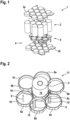
- Figure 1 shows in an exploded view part of a battery cell holder according to an embodiment of the present invention
- Figure 2 shows a holding element of a battery cell holder according to an embodiment of the present invention
- Figure 3 shows a cell holding system according to an embodiment of the present invention.
- a battery cell holder 1 comprising an upper half shell 3a and a lower half shell 3b. Between the lower and upper half shell 3a, 3b, a plurality of ring-shaped holding elements 5 are arranged. The lower and upper half shell 3a, 3b together with the holding elements 5 provide a fixing of cylindrical battery cells 2 arranged between the lower and upper half shell 3a, 3b and in the ring-shaped holding elements 5. The remaining space 4 in which part of the circumferential surface 14 of the battery cells 2 is accessible, is used to be applied with a cooling fluid like a dielectric fluid to cool the battery cells 2 in operation.
- FIG. 2 shows a single holding element 5 with an inserted cylindrical battery cell 2 with circumferential surface 14.
- the holding element 5 has a central holding structure 8c in form of a ring.
- On the outer circumference of the central holding structure 8c a plurality of similar ring-shaped holding structures 8a, 8b are arranged, here six holding structures 8a, 8b.
- Adjacent holding structures 8a, 8b are arranged on different vertical levels (vertical axis 9 corresponds to the symmetry axis of the ring shaped holding structures 8a, 8b, 8c or of the battery cells 2) with distance 10, such that on top of the lower holding structures 8a, an upper holding structure 8b of another holding element 5 can be arranged.
- the upper and lower holding structure 8a, 8b are overlapping, such that within said both lower and upper holding structure 8a, 8b, a battery cell 2 can be arranged.
- This allows for a fixing of adjacent holding elements 5 not only by the half shells 3a, 3b but also by the battery cells 2, which may be additionally fixed by the half shells 3a, 3b.
- the holding element 5 comprises a hexagonal structure 11 of holding elements 8a, 8b with a center holding element 8c.
- the outer surface of the ring shaped holding structures 8a, 8b, 8c may have one or more flat areas 16, such that adjacent holding elements 5 with their holding structures 8a, 8b, 8c can lie flat against each other.
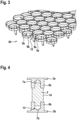
- a battery cell 2 is shown, fixed at the upper and lower side by holding clamps 6a, 6b of the respective upper and lower shell 3a, 3b.
- the holding clamps 6a, 6b grip partially a part of the lower and upper circumferential surface 14 of the battery cell 2 such that the battery cell 2 is securely fixed.
- the holding clamps 6a, 6b each provide a thermal management channel with T-shaped cross-sections 13 for a cooling fluid or the like to cool the upper and lower end of the battery cell 2, which are arranged within the holding clamps 6a, 6b.
Landscapes
- Chemical & Material Sciences (AREA)
- Chemical Kinetics & Catalysis (AREA)
- Electrochemistry (AREA)
- General Chemical & Material Sciences (AREA)
- Engineering & Computer Science (AREA)
- Manufacturing & Machinery (AREA)
- Secondary Cells (AREA)
- Battery Mounting, Suspending (AREA)
Abstract
This invention relates to a battery cell holder for thermal management, in particular for immersion thermal management, of a plurality of battery cells, comprising a first shell, a second shell, wherein the first shell and the second shell are attachable to each other forming a sealed inner space for arranging a plurality of battery cells within said inner space and wherein a thermal management fluid can be applied to the inner space for thermal management, preferably cooling the battery cells, wherein
a) at least one holding element separated from the first and second shell being adapted to fix a position of at least two of said plurality of battery cells and/or wherein
b) the first shell and/or the second shell are provided with fixing elements adapted to provide a fixing function for said plurality of battery cells, wherein the first shell and/or the second shell comprise at least one thermal management channel for thermal management of at least a part of the battery cells fixed by the first shell and/or the second shell.
Description
- The present invention relates to a battery cell holder for thermal management, in particular for immersion thermal management, of a plurality of battery cells, comprising a first shell, a second shell, wherein the first shell and the second shell are attachable to each other forming a sealed inner space for arranging a plurality of battery cells within said inner space and wherein a thermal management fluid can be applied to the inner space for thermal management, preferably cooling the battery cells.
- The present invention further relates to a thermal management structure for a battery, comprising a battery cell holder and a plurality of battery cells for arranging in said battery cell holder.
- The present invention further relates to a cell holding system comprising a battery cell holder with at least two holding elements.
- The present invention even further relates to a battery, comprising a thermal management structure and a thermal management device, connectable to an inlet of said thermal management structure, for providing a thermal management fluid.
- Devices for thermal management of battery cells are for instance known from
EP 3 525 279 A1 .EP 3 525 279 A1 discloses a battery pack with a flexible foil, which can be integrated with or coupled to a heat exchanging member, wherein the heat exchanging member is arranged to fit around the plurality of battery cells. The heat exchanging member can comprise means for guiding a cooling liquid there through for enhancing the cooling. - One of the problems however is that the flexible foil has to be elaborately placed between the different battery cells. A further problem is that an inefficient thermal management of the battery cells is provided with non-contact areas in which the flexible foil is not in contact with a surface of the battery cell. A further problem is that due to the foil structure, i.e. the small thickness, the thermal contact between the battery cells depends on the pressure of the cooling liquid inside the associated heat exchanging member and therefore can be limited.
- To overcome these problems,
WO 2017/067923 A1 discloses a temperature control device for a battery system, the battery system comprising a cuboid hollow body with at least one connection device for supplying and at least one connection device for discharging a separately temperature-controlled fluid, a plurality of regularly arranged and identically formed apertures extending from a first body surface to a second body surface, wherein a cylindrical battery cell is accommodated by each aperture, so that a fluid-tight liquid space is formed. - One of the disadvantages is however that an inefficient thermal management is provided, in particular at the upper and lower end faces of a battery cell. One of the further disadvantages is the non-uniform cooling due to the inefficient flow of the thermal management fluid. An even further disadvantage is that the provided structure has a large weight.
- One of the objectives of the present invention is therefore to provide a battery cell holder, a thermal management structure, a cell holding system and a battery, which provide a larger contact area of the surface for the thermal management and a flexible and sufficient thermal management while providing a lesser weight, an increased structural stability allowing for safety in normal conditions and a faster charging/discharging of the battery cells.
- One of the further objectives of the present invention is to provide an alternative battery cell holder, an alternative thermal management structure, an alternative cell holding system and an alternative battery.
- The above-mentioned objectives may be solved by a battery cell holder for thermal management, in particular for immersion thermal management, of a plurality of battery cells, comprising
- a first shell,
- a second shell, wherein the first shell and the second shell are attachable to each other forming a sealed inner space for arranging a plurality of battery cells within said inner space and wherein a thermal management fluid can be applied to the inner space for thermal management, preferably cooling the battery cells,
- characterized in that
- a) at least one holding element separated from the first and second shell being adapted to fix a position of at least two of said plurality of battery cells and/or that
- b) the first shell and/or the second shell are provided with fixing elements adapted to provide a fixing function for said plurality of battery cells, wherein the first shell and/or the second shell comprise at least one thermal management channel for thermal management of at least a part of the battery cells fixed by the first shell and/or the second shell.
- The above-mentioned objectives may be solved by a thermal management structure for a battery, comprising a battery cell holder according to one of the claims 1-11 and a plurality of battery cells for arranging in said battery cell holder.
- The above-mentioned objectives may be solved by a cell holding system, comprising a battery cell holder according to one of the claims 1-11, with at least two holding elements, wherein at least one holding structure of each of said at least two holding elements is arranged such to hold a same battery cell.
- The above-mentioned objectives may be solved by a battery, comprising a thermal management structure according to one of the claims 12-13 and a thermal management device, connectable to an inlet of said thermal management structure, for providing a thermal management fluid, preferably a cooling fluid, to said thermal management structure for immersion thermal management of said battery cells, preferably wherein said cooling fluid is an electrically insulating fluid, preferably a dielectric fluid.
- One of the advantages that may be achieved by the present invention is that a larger contact area of the surface for the thermal management and a flexible and sufficient thermal management is provided. A further advantage is that a lesser weight is enabled while allowing for an increased structural stability. This allows for safety in normal conditions and a faster charging/discharging of the battery cells.
- Further features, advantages and preferred embodiments are disclosed or may become apparent in the following.
- According to a preferred embodiment, said at least one holding element comprises a plurality of holding structures, each for a battery cell. This may allow for an increased stability while providing sufficient support for a plurality of battery cells.
- According to a further preferred embodiment, a holding structure, at least partly, preferably completely, provides a ring-shaped reception for insertion of a battery cell. This may allow for a reliable fixing and an easy insertion of a cylindrical battery cell.
- According to a further preferred embodiment, adjacent holding structures are offset to each other, preferably along a symmetry axis of the holding element. This may allow for an enhanced thermal management, since a thermal management fluid can be applied to a large surface area of each battery cell.
- According to a further preferred embodiment, said holding structures of said at least one holding element are arranged in a regular hexagon structure around a center of said holding element, preferably wherein the center of said hexagon structure is provided as a holding structure. This may allow for a dense packaging of cylindrical battery cells.
- According to a further preferred embodiment, said at least one holding element comprises at least one distance element for spacing said at least one holding element from the first shell and/or the second shell. This may allow for a large surface area to which a thermal management fluid can be applied, while providing sufficient support for fixing the battery cells.
- According to a further preferred embodiment, said at least one distance element is adapted to be, preferably releasably, connectable to said first shell and/or said second shell, in particular by insertion of said at least one distance element into said first shell and/or said second shell. This may allow for an easy arrangement of the holding element.
- According to a further preferred embodiment, said at least one distance element is adapted to space apart at least two adjacent battery cells when arranged in adjacent holding structures. This may allow for a more secure arrangement of the battery cells supporting the battery cells in case of a movement of the battery cells.
- According to a further preferred embodiment, a plurality of distance elements is provided, arranged symmetrically to each other at said at least one holding element. This may allow for further enhancing the secure arrangement of the battery cells within the holding element.
- According to a further preferred embodiment, said at least one thermal management channel has a T-shaped cross section. This may allow for a stable fixing of the battery cells with the first and second shell while providing a sufficient thermal management of the top and bottom of the battery cells enabling a flow of a thermal management fluid.
- According to a further preferred embodiment, said at least one holding element, said first shell and/or said second shell are made of plastic. This may allow for a lightweight holding element or battery cell holder respectively.
- According to a further preferred embodiment, a holding structure of a holding element covers 50% or less of a circumferential surface of a battery cell, preferably 40% or less, in particular 30% or less, preferably 20% or less, in particular 15% or less, preferably 10% or less, preferably 5% or less and 1 % or more, preferably 2% or more, preferably 4% or more, preferably 10% or more. This may allow for an efficient thermal management of the battery cells since a large area of the surface of each battery cell can be provided for applying a thermal management fluid.
- According to a further preferred embodiment, the battery cells have cylindrical form and said holding elements are at least in part ring-shaped to hold the battery cells and/or that said at least one holding element is arranged between 40% and 60% of the distance in the inner space between the first shell and the second shell, preferably between 45% and 55%, preferably centrally. This may allow for a sufficient holding of the battery cells while providing a flexibility in terms of location of the holding element between the two shells.
- There are several ways how to design and further develop the teaching of the present invention in an advantageous way. To this end, it is to be referred to the patent claims subordinate to the independent claims on the one hand and to the following explanation of further embodiments of the invention by way of example, illustrated by the figures on the other hand. In connection with the explanation of the further embodiments of the invention by the aid of the figures, generally further embodiments and further developments of the teaching will be explained.
- In the drawings
- Fig. 1
- shows in an exploded view part of a battery cell holder according to an embodiment of the present invention;
- Fig. 2
- shows a holding element of a battery cell holder according to an embodiment of the present invention;
- Fig. 3
- shows a cell holding system according to an embodiment of the present invention; and
- Fig. 4
- shows a cross-section of a battery cell holder according to an embodiment of the present invention.
-
Figure 1 shows in an exploded view part of a battery cell holder according to an embodiment of the present invention,Figure 2 shows a holding element of a battery cell holder according to an embodiment of the present invention andFigure 3 shows a cell holding system according to an embodiment of the present invention. - In
Figure 1 a battery cell holder 1 is shown, comprising anupper half shell 3a and alower half shell 3b. Between the lower and upperhalf shell holding elements 5 are arranged. The lower and upperhalf shell elements 5 provide a fixing ofcylindrical battery cells 2 arranged between the lower and upperhalf shell holding elements 5. The remainingspace 4 in which part of thecircumferential surface 14 of thebattery cells 2 is accessible, is used to be applied with a cooling fluid like a dielectric fluid to cool thebattery cells 2 in operation. -
Figure 2 shows asingle holding element 5 with an insertedcylindrical battery cell 2 withcircumferential surface 14. The holdingelement 5 has acentral holding structure 8c in form of a ring. On the outer circumference of thecentral holding structure 8c a plurality of similar ring-shapedholding structures structures Adjacent holding structures vertical axis 9 corresponds to the symmetry axis of the ring shaped holdingstructures distance 10, such that on top of thelower holding structures 8a, anupper holding structure 8b of another holdingelement 5 can be arranged. In this way, the upper andlower holding structure upper holding structure battery cell 2 can be arranged. This allows for a fixing ofadjacent holding elements 5 not only by thehalf shells battery cells 2, which may be additionally fixed by thehalf shells element 5 comprises ahexagonal structure 11 of holdingelements center holding element 8c. - Further, the holding
element 5 comprises elongateddistance elements 12, which have their main extension along theaxis 9, which on the one hand can be attached to the upper and/orlower shell adjacent battery cells 2 when being arranged within the holdingstructures - The outer surface of the ring shaped holding
structures flat areas 16, such thatadjacent holding elements 5 with theirholding structures -
Figure 3 shows anarrangement 50 of a plurality ofdifferent holdings elements lower holding structures 8a and theirupper holding structures 8b being arranged such to form an overlappingregion 15, in which anupper holding structure 8b of a holdingelement 5b is arranged on top of alower holding structure 8a of anadjacent holding element 5a. -
Figure 4 shows a cross-section of a battery cell holder according to an embodiment of the present invention. - In
Figure 4 abattery cell 2 is shown, fixed at the upper and lower side by holdingclamps lower shell circumferential surface 14 of thebattery cell 2 such that thebattery cell 2 is securely fixed. The holding clamps 6a, 6b each provide a thermal management channel with T-shapedcross-sections 13 for a cooling fluid or the like to cool the upper and lower end of thebattery cell 2, which are arranged within the holdingclamps - These
thermal management channels clamp battery cells 2 as shown inFigure 3 , to each other such that a continuous flow of a thermal management fluid in a common direction can be provided. - The
shells elements 5, the holdingstructures clamps - The thermal management fluid can be a cooling fluid, in particular a dielectric or nonconductive fluid, in particular the fluid can be a liquid.
- At least one embodiment may provide at least one of the following features and/or at least one of the following advantages:
- Easy and less cost-intensive manufacturing.
- Higher reliability of the operation of the battery cells.
- High integration level.
- Easy and secure arrangement of the battery cells.
- A larger contact area of the surface of the battery cells for the thermal management.
- Flexible and sufficient thermal management.
- Lesser weight compared to conventional battery cell holders.
- Many modifications and other embodiments of the invention set forth herein will come to mind to the one skilled in the art to which the invention pertains having the benefit of the teachings presented in the foregoing description and the associated drawings. Therefore, it is to be understood that the invention is not to be limited to the specific embodiments disclosed and that modifications and other embodiments are intended to be included within the scope of the appended claims. Although specific terms are employed herein, they are used in a generic and descriptive sense only and not for purposes of limitation.
-
- 1
- Battery cell holder
- 2
- Battery cell
- 3a
- Upper half shell
- 3b
- Lower half shell
- 4
- Inner space
- 5, 5a, 5b
- Holding element
- 6a, 6b
- Holding clamp
- 7a, 7b
- Thermal management channel
- 8a
- Lower holding structure
- 8b
- Upper holding structure
- 8c
- Central holding structure
- 9
- Vertical axis
- 10
- Distance
- 11
- Hexagonal structure
- 12
- Distance element
- 13
- T-shaped cross-section
- 14
- Circumferential surface
- 15
- Overlapping region
- 16
- Flat area
- 50
- Holding element arrangement
Claims (15)
- Battery cell holder (1) for thermal management, in particular for immersion thermal management, of a plurality of battery cells (2), comprisinga first shell (3a),a second shell (3b), wherein the first shell (3a) and the second shell (3b) are attachable to each other forming a sealed inner space (4) for arranging a plurality of battery cells (2) within said inner space (4) and wherein a thermal management fluid can be applied to the inner space (4) for thermal management, preferably cooling the battery cells (2),characterized in thata) at least one holding element (5, 5a, 5b) separated from the first and second shell (3a, 3b) being adapted to fix a position of at least two of said plurality of battery cells (2) and/or thatb) the first shell (3a) and/or the second shell (3b) are provided with fixing elements (6a, 6b) adapted to provide a fixing function for said plurality of battery cells (2), wherein the first shell (3a) and/or the second shell (3b) comprise at least one thermal management channel (7a, 7b) for thermal management of at least a part of the battery cells (2) fixed by the first shell (3a) and/or the second shell (3b).
- Battery cell holder (1) according to claim 1, characterized in that said at least one holding element (5, 5a, 5b) comprises a plurality of holding structures (8a, 8b, 8c), each for a battery cell (2).
- Battery cell holder (1) according to claim 2, characterized in that a holding structure (8a, 8b, 8c), at least partly, preferably completely, provides a ring-shaped reception for insertion of a battery cell (2).
- Battery cell holder (1) according to claim 2 or 3, characterized in that adjacent holding structures (8a, 8b) are offset to each other, preferably along a symmetry axis (9) of the holding element (5, 5a, 5b).
- Battery cell holder (1) according to one of the claims 2-4, characterized in that said holding structures (8a, 8b) of said at least one holding element (5, 5a, 5b) are arranged in a regular hexagon structure (11) around a center of said holding element (5, 5a, 5b), preferably wherein the center of said hexagon structure (11) is provided as a holding structure (8c).
- Battery cell holder (1) according to one of the claims 1-5, characterized in that said at least one holding element (5, 5a, 5b) comprises at least one distance element (12) for spacing said at least one holding element (5, 5a, 5b) from the first shell (3a) and/or the second shell (3b).
- Battery cell holder (1) according to claim 6, characterized in that said at least one distance element (12) is adapted to be, preferably releasably, connectable to said first shell (3a) and/or said second shell (3b), in particular by insertion of said at least one distance element (12) into said first shell (3a) and/or said second shell (3b).
- Battery cell holder (1) according to claim 7, characterized in that said at least one distance element (12) is adapted to space apart at least two adjacent battery cells (2) when arranged in adjacent holding structures (8a, ,8b, 8c).
- Battery cell holder (1) according to one of the claims 6-8, characterized in that a plurality of distance elements (12) is provided, arranged symmetrically to each other at said at least one holding element (5, 5a, 5b).
- Battery cell holder (1) according to one of the claims 1-9, characterized in that said at least one thermal management channel (7a, 7b) has a T-shaped cross section (13).
- Battery cell holder (1) according to one of the claims 1-10, characterized in that said at least one holding element (5, 5a, 5b), said first shell (3a) and/or said second shell (3b) are made of plastic.
- Thermal management structure for a battery, comprising a battery cell holder (1) according to one of the claims 1-11 and a plurality of battery cells (2) for arranging in said battery cell holder (1), preferably wherein a holding structure (8a, 8b, 8c) of a holding element (5, 5a, 5b) covers 50% or less of a circumferential surface (14) of a battery cell (2), preferably 40% or less, in particular 30% or less, preferably 20% or less, in particular 15% or less, preferably 10% or less, preferably 5% or less and 1% or more, preferably 2% or more, preferably 4% or more, preferably 10% or more.
- Thermal management structure according to claim 12, characterized in that the battery cells (2) have cylindrical form and said holding elements (5, 5a, 5b) are at least in part ring-shaped to hold the battery cells (2) and/or that said at least one holding element (5, 5a, 5b) is arranged between 40% and 60% of the distance (10) in the inner space (4) between the first shell (3a) and the second shell (3b), preferably between 45% and 55%, preferably centrally.
- Cell holding system (50) comprising a battery cell holder (1) according to one of the claims 1-11, with at least two holding elements (5, 5a, 5b), wherein at least one holding structure (8a, 8b, 8c) of each of said at least two holding elements (5, 5a, 5b) is arranged such to hold a same battery cell (2).
- Battery comprising a thermal management structure according to one of the claims 12-13 and a thermal management device, connectable to an inlet of said thermal management structure, for providing a thermal management fluid, preferably a cooling fluid, to said thermal management structure for immersion thermal management of said battery cells (2), preferably wherein said cooling fluid is an electrically insulating fluid, preferably a dielectric fluid.
Priority Applications (2)
| Application Number | Priority Date | Filing Date | Title |
|---|---|---|---|
| EP23218319.4A EP4576326A1 (en) | 2023-12-19 | 2023-12-19 | Battery cell holder for thermal management of a plurality of battery cells |
| US18/983,921 US20250201968A1 (en) | 2023-12-19 | 2024-12-17 | Battery cell holder for thermal management of a plurality of battery cells |
Applications Claiming Priority (1)
| Application Number | Priority Date | Filing Date | Title |
|---|---|---|---|
| EP23218319.4A EP4576326A1 (en) | 2023-12-19 | 2023-12-19 | Battery cell holder for thermal management of a plurality of battery cells |
Publications (1)
| Publication Number | Publication Date |
|---|---|
| EP4576326A1 true EP4576326A1 (en) | 2025-06-25 |
Family
ID=89224607
Family Applications (1)
| Application Number | Title | Priority Date | Filing Date |
|---|---|---|---|
| EP23218319.4A Pending EP4576326A1 (en) | 2023-12-19 | 2023-12-19 | Battery cell holder for thermal management of a plurality of battery cells |
Country Status (2)
| Country | Link |
|---|---|
| US (1) | US20250201968A1 (en) |
| EP (1) | EP4576326A1 (en) |
Citations (8)
| Publication number | Priority date | Publication date | Assignee | Title |
|---|---|---|---|---|
| WO2016117685A1 (en) * | 2015-01-23 | 2016-07-28 | 日立化成株式会社 | Electrical storage unit |
| WO2017067923A1 (en) | 2015-10-18 | 2017-04-27 | Kreisel Electric GmbH | Temperature-control device for a battery system |
| WO2017169728A1 (en) * | 2016-03-30 | 2017-10-05 | 三洋電機株式会社 | Battery pack |
| DE102016220989A1 (en) * | 2016-10-25 | 2018-04-26 | Robert Bosch Gmbh | Battery cell holder for resiliently receiving at least one battery cell, battery module housing and battery module and method for producing the battery module |
| EP3525279A1 (en) | 2018-02-09 | 2019-08-14 | Nederlandse Organisatie voor toegepast- natuurwetenschappelijk onderzoek TNO | Thermistors on flexible layers and its use for temperature measurements within a battery pack |
| EP3690981A1 (en) * | 2019-02-01 | 2020-08-05 | Robert Bosch GmbH | Cell holder for holding battery cells |
| US20230170551A1 (en) * | 2020-04-24 | 2023-06-01 | Tvs Motor Company Limited | Battery module with a cell holder assembly |
| WO2023147615A1 (en) * | 2022-02-04 | 2023-08-10 | Fiberdraft E.U. | Energy storage stack, energy storage module, and method for producing energy storage modules |
-
2023
- 2023-12-19 EP EP23218319.4A patent/EP4576326A1/en active Pending
-
2024
- 2024-12-17 US US18/983,921 patent/US20250201968A1/en active Pending
Patent Citations (8)
| Publication number | Priority date | Publication date | Assignee | Title |
|---|---|---|---|---|
| WO2016117685A1 (en) * | 2015-01-23 | 2016-07-28 | 日立化成株式会社 | Electrical storage unit |
| WO2017067923A1 (en) | 2015-10-18 | 2017-04-27 | Kreisel Electric GmbH | Temperature-control device for a battery system |
| WO2017169728A1 (en) * | 2016-03-30 | 2017-10-05 | 三洋電機株式会社 | Battery pack |
| DE102016220989A1 (en) * | 2016-10-25 | 2018-04-26 | Robert Bosch Gmbh | Battery cell holder for resiliently receiving at least one battery cell, battery module housing and battery module and method for producing the battery module |
| EP3525279A1 (en) | 2018-02-09 | 2019-08-14 | Nederlandse Organisatie voor toegepast- natuurwetenschappelijk onderzoek TNO | Thermistors on flexible layers and its use for temperature measurements within a battery pack |
| EP3690981A1 (en) * | 2019-02-01 | 2020-08-05 | Robert Bosch GmbH | Cell holder for holding battery cells |
| US20230170551A1 (en) * | 2020-04-24 | 2023-06-01 | Tvs Motor Company Limited | Battery module with a cell holder assembly |
| WO2023147615A1 (en) * | 2022-02-04 | 2023-08-10 | Fiberdraft E.U. | Energy storage stack, energy storage module, and method for producing energy storage modules |
Also Published As
| Publication number | Publication date |
|---|---|
| US20250201968A1 (en) | 2025-06-19 |
Similar Documents
| Publication | Publication Date | Title |
|---|---|---|
| EP4142029B1 (en) | Battery module having structure capable of absorbing cell swelling, and battery pack and vehicle comprising same | |
| EP3790074B1 (en) | Battery pack | |
| ES2690480T5 (en) | Battery module and battery system | |
| EP4210158A2 (en) | Battery pack | |
| EP1701404A1 (en) | Battery module | |
| EP3121869B1 (en) | Battery cell holder member | |
| JP7309910B2 (en) | Battery module including cell frame | |
| ES2822996T3 (en) | Energy storage device and cell holder for an energy storage device | |
| US8507120B2 (en) | Round cell battery | |
| EP2450990B1 (en) | Battery module having battery cell holder | |
| EP2887423A1 (en) | Battery module | |
| US4443523A (en) | High-temperature battery | |
| US20060103346A1 (en) | Secondary battery structure | |
| ES2792104T3 (en) | Electrolytic cell including elastic member | |
| JP2006156406A (en) | Secondary battery module | |
| EP4576326A1 (en) | Battery cell holder for thermal management of a plurality of battery cells | |
| KR20230025417A (en) | Battery pack | |
| JP4649422B2 (en) | Collective battery end plate | |
| KR20170021779A (en) | Magazine for storing bar-shaped workpieces for a machine tool | |
| US20250266557A1 (en) | Battery-cushioning member | |
| JP6641711B2 (en) | Battery module | |
| US12586836B2 (en) | Battery module | |
| US20200119415A1 (en) | Accumulator | |
| EP4583250A1 (en) | Battery module, cooling plate, and battery pack | |
| EP2569586B1 (en) | Partial reverse ferrule header for a heat exchanger |
Legal Events
| Date | Code | Title | Description |
|---|---|---|---|
| STAA | Information on the status of an ep patent application or granted ep patent |
Free format text: STATUS: EXAMINATION IS IN PROGRESS |
|
| PUAI | Public reference made under article 153(3) epc to a published international application that has entered the european phase |
Free format text: ORIGINAL CODE: 0009012 |
|
| 17P | Request for examination filed |
Effective date: 20231219 |
|
| AK | Designated contracting states |
Kind code of ref document: A1 Designated state(s): AL AT BE BG CH CY CZ DE DK EE ES FI FR GB GR HR HU IE IS IT LI LT LU LV MC ME MK MT NL NO PL PT RO RS SE SI SK SM TR |