EP4576323A1 - Battery module and battery pack - Google Patents
Battery module and battery pack Download PDFInfo
- Publication number
- EP4576323A1 EP4576323A1 EP24192107.1A EP24192107A EP4576323A1 EP 4576323 A1 EP4576323 A1 EP 4576323A1 EP 24192107 A EP24192107 A EP 24192107A EP 4576323 A1 EP4576323 A1 EP 4576323A1
- Authority
- EP
- European Patent Office
- Prior art keywords
- pressure relief
- air
- receiving space
- detection unit
- battery
- Prior art date
- Legal status (The legal status is an assumption and is not a legal conclusion. Google has not performed a legal analysis and makes no representation as to the accuracy of the status listed.)
- Pending
Links
Images



Classifications
-
- H—ELECTRICITY
- H01—ELECTRIC ELEMENTS
- H01M—PROCESSES OR MEANS, e.g. BATTERIES, FOR THE DIRECT CONVERSION OF CHEMICAL ENERGY INTO ELECTRICAL ENERGY
- H01M50/00—Constructional details or processes of manufacture of the non-active parts of electrochemical cells other than fuel cells, e.g. hybrid cells
- H01M50/30—Arrangements for facilitating escape of gases
- H01M50/317—Re-sealable arrangements
- H01M50/325—Re-sealable arrangements comprising deformable valve members, e.g. elastic or flexible valve members
- H01M50/333—Spring-loaded vent valves
-
- F—MECHANICAL ENGINEERING; LIGHTING; HEATING; WEAPONS; BLASTING
- F16—ENGINEERING ELEMENTS AND UNITS; GENERAL MEASURES FOR PRODUCING AND MAINTAINING EFFECTIVE FUNCTIONING OF MACHINES OR INSTALLATIONS; THERMAL INSULATION IN GENERAL
- F16K—VALVES; TAPS; COCKS; ACTUATING-FLOATS; DEVICES FOR VENTING OR AERATING
- F16K17/00—Safety valves; Equalising valves, e.g. pressure relief valves
- F16K17/02—Safety valves; Equalising valves, e.g. pressure relief valves opening on surplus pressure on one side; closing on insufficient pressure on one side
-
- F—MECHANICAL ENGINEERING; LIGHTING; HEATING; WEAPONS; BLASTING
- F16—ENGINEERING ELEMENTS AND UNITS; GENERAL MEASURES FOR PRODUCING AND MAINTAINING EFFECTIVE FUNCTIONING OF MACHINES OR INSTALLATIONS; THERMAL INSULATION IN GENERAL
- F16K—VALVES; TAPS; COCKS; ACTUATING-FLOATS; DEVICES FOR VENTING OR AERATING
- F16K31/00—Actuating devices; Operating means; Releasing devices
- F16K31/02—Actuating devices; Operating means; Releasing devices electric; magnetic
- F16K31/06—Actuating devices; Operating means; Releasing devices electric; magnetic using a magnet, e.g. diaphragm valves, cutting off by means of a liquid
- F16K31/0644—One-way valve
-
- H—ELECTRICITY
- H01—ELECTRIC ELEMENTS
- H01M—PROCESSES OR MEANS, e.g. BATTERIES, FOR THE DIRECT CONVERSION OF CHEMICAL ENERGY INTO ELECTRICAL ENERGY
- H01M10/00—Secondary cells; Manufacture thereof
- H01M10/42—Methods or arrangements for servicing or maintenance of secondary cells or secondary half-cells
- H01M10/425—Structural combination with electronic components, e.g. electronic circuits integrated to the outside of the casing
-
- H—ELECTRICITY
- H01—ELECTRIC ELEMENTS
- H01M—PROCESSES OR MEANS, e.g. BATTERIES, FOR THE DIRECT CONVERSION OF CHEMICAL ENERGY INTO ELECTRICAL ENERGY
- H01M10/00—Secondary cells; Manufacture thereof
- H01M10/42—Methods or arrangements for servicing or maintenance of secondary cells or secondary half-cells
- H01M10/48—Accumulators combined with arrangements for measuring, testing or indicating the condition of cells, e.g. the level or density of the electrolyte
-
- H—ELECTRICITY
- H01—ELECTRIC ELEMENTS
- H01M—PROCESSES OR MEANS, e.g. BATTERIES, FOR THE DIRECT CONVERSION OF CHEMICAL ENERGY INTO ELECTRICAL ENERGY
- H01M10/00—Secondary cells; Manufacture thereof
- H01M10/42—Methods or arrangements for servicing or maintenance of secondary cells or secondary half-cells
- H01M10/48—Accumulators combined with arrangements for measuring, testing or indicating the condition of cells, e.g. the level or density of the electrolyte
- H01M10/486—Accumulators combined with arrangements for measuring, testing or indicating the condition of cells, e.g. the level or density of the electrolyte for measuring temperature
-
- H—ELECTRICITY
- H01—ELECTRIC ELEMENTS
- H01M—PROCESSES OR MEANS, e.g. BATTERIES, FOR THE DIRECT CONVERSION OF CHEMICAL ENERGY INTO ELECTRICAL ENERGY
- H01M50/00—Constructional details or processes of manufacture of the non-active parts of electrochemical cells other than fuel cells, e.g. hybrid cells
- H01M50/20—Mountings; Secondary casings or frames; Racks, modules or packs; Suspension devices; Shock absorbers; Transport or carrying devices; Holders
- H01M50/204—Racks, modules or packs for multiple batteries or multiple cells
- H01M50/207—Racks, modules or packs for multiple batteries or multiple cells characterised by their shape
- H01M50/209—Racks, modules or packs for multiple batteries or multiple cells characterised by their shape adapted for prismatic or rectangular cells
-
- H—ELECTRICITY
- H01—ELECTRIC ELEMENTS
- H01M—PROCESSES OR MEANS, e.g. BATTERIES, FOR THE DIRECT CONVERSION OF CHEMICAL ENERGY INTO ELECTRICAL ENERGY
- H01M50/00—Constructional details or processes of manufacture of the non-active parts of electrochemical cells other than fuel cells, e.g. hybrid cells
- H01M50/20—Mountings; Secondary casings or frames; Racks, modules or packs; Suspension devices; Shock absorbers; Transport or carrying devices; Holders
- H01M50/258—Modular batteries; Casings provided with means for assembling
-
- H—ELECTRICITY
- H01—ELECTRIC ELEMENTS
- H01M—PROCESSES OR MEANS, e.g. BATTERIES, FOR THE DIRECT CONVERSION OF CHEMICAL ENERGY INTO ELECTRICAL ENERGY
- H01M50/00—Constructional details or processes of manufacture of the non-active parts of electrochemical cells other than fuel cells, e.g. hybrid cells
- H01M50/30—Arrangements for facilitating escape of gases
- H01M50/35—Gas exhaust passages comprising elongated, tortuous or labyrinth-shaped exhaust passages
- H01M50/358—External gas exhaust passages located on the battery cover or case
-
- H—ELECTRICITY
- H01—ELECTRIC ELEMENTS
- H01M—PROCESSES OR MEANS, e.g. BATTERIES, FOR THE DIRECT CONVERSION OF CHEMICAL ENERGY INTO ELECTRICAL ENERGY
- H01M50/00—Constructional details or processes of manufacture of the non-active parts of electrochemical cells other than fuel cells, e.g. hybrid cells
- H01M50/30—Arrangements for facilitating escape of gases
- H01M50/375—Vent means sensitive to or responsive to temperature
-
- H—ELECTRICITY
- H01—ELECTRIC ELEMENTS
- H01M—PROCESSES OR MEANS, e.g. BATTERIES, FOR THE DIRECT CONVERSION OF CHEMICAL ENERGY INTO ELECTRICAL ENERGY
- H01M10/00—Secondary cells; Manufacture thereof
- H01M10/60—Heating or cooling; Temperature control
- H01M10/65—Means for temperature control structurally associated with the cells
- H01M10/656—Means for temperature control structurally associated with the cells characterised by the type of heat-exchange fluid
- H01M10/6561—Gases
-
- H—ELECTRICITY
- H01—ELECTRIC ELEMENTS
- H01M—PROCESSES OR MEANS, e.g. BATTERIES, FOR THE DIRECT CONVERSION OF CHEMICAL ENERGY INTO ELECTRICAL ENERGY
- H01M10/00—Secondary cells; Manufacture thereof
- H01M10/42—Methods or arrangements for servicing or maintenance of secondary cells or secondary half-cells
- H01M10/425—Structural combination with electronic components, e.g. electronic circuits integrated to the outside of the casing
- H01M2010/4271—Battery management systems including electronic circuits, e.g. control of current or voltage to keep battery in healthy state, cell balancing
-
- H—ELECTRICITY
- H01—ELECTRIC ELEMENTS
- H01M—PROCESSES OR MEANS, e.g. BATTERIES, FOR THE DIRECT CONVERSION OF CHEMICAL ENERGY INTO ELECTRICAL ENERGY
- H01M2200/00—Safety devices for primary or secondary batteries
- H01M2200/10—Temperature sensitive devices
-
- H—ELECTRICITY
- H01—ELECTRIC ELEMENTS
- H01M—PROCESSES OR MEANS, e.g. BATTERIES, FOR THE DIRECT CONVERSION OF CHEMICAL ENERGY INTO ELECTRICAL ENERGY
- H01M2200/00—Safety devices for primary or secondary batteries
- H01M2200/20—Pressure-sensitive devices
-
- H—ELECTRICITY
- H01—ELECTRIC ELEMENTS
- H01M—PROCESSES OR MEANS, e.g. BATTERIES, FOR THE DIRECT CONVERSION OF CHEMICAL ENERGY INTO ELECTRICAL ENERGY
- H01M50/00—Constructional details or processes of manufacture of the non-active parts of electrochemical cells other than fuel cells, e.g. hybrid cells
- H01M50/30—Arrangements for facilitating escape of gases
-
- H—ELECTRICITY
- H01—ELECTRIC ELEMENTS
- H01M—PROCESSES OR MEANS, e.g. BATTERIES, FOR THE DIRECT CONVERSION OF CHEMICAL ENERGY INTO ELECTRICAL ENERGY
- H01M50/00—Constructional details or processes of manufacture of the non-active parts of electrochemical cells other than fuel cells, e.g. hybrid cells
- H01M50/30—Arrangements for facilitating escape of gases
- H01M50/317—Re-sealable arrangements
- H01M50/325—Re-sealable arrangements comprising deformable valve members, e.g. elastic or flexible valve members
-
- Y—GENERAL TAGGING OF NEW TECHNOLOGICAL DEVELOPMENTS; GENERAL TAGGING OF CROSS-SECTIONAL TECHNOLOGIES SPANNING OVER SEVERAL SECTIONS OF THE IPC; TECHNICAL SUBJECTS COVERED BY FORMER USPC CROSS-REFERENCE ART COLLECTIONS [XRACs] AND DIGESTS
- Y02—TECHNOLOGIES OR APPLICATIONS FOR MITIGATION OR ADAPTATION AGAINST CLIMATE CHANGE
- Y02E—REDUCTION OF GREENHOUSE GAS [GHG] EMISSIONS, RELATED TO ENERGY GENERATION, TRANSMISSION OR DISTRIBUTION
- Y02E60/00—Enabling technologies; Technologies with a potential or indirect contribution to GHG emissions mitigation
- Y02E60/10—Energy storage using batteries
Definitions
- the present disclosure relates to the field of batteries, and in particular to a battery module and a battery pack.
- the battery module has been widely used in various new-energy vehicles and energy storage power stations.
- the battery module When the battery module is in use, if a short circuit occurs or the battery module is over-charged, a large amount of heat may be accumulated inside the battery module, such that thermal runaway may be caused, resulting in an internal pressure of the battery module being excessively high to cause fire or even explosion.
- a pressure relief valve is mounted on the battery module.
- the pressure relief valve is flushed to be open to release the internal pressure of the battery module, i.e., a passive resealing method is achieved.
- the pressure relief valve may be unable to be flushed to be open, such that the internal pressure of the battery module cannot be released.
- the present disclosure provides a battery module and a battery pack, to proactively discharge the air. A situation in which, even though thermal runaway of the cell occurs, the internal pressure of the housing does not flush to open the pressure relief valve, may be avoided.
- a battery module in a first aspect, includes: a housing, a cell, and a first detection unit.
- the housing defines a receiving space, a pressure relief port communicated with the receiving space, and a first air inlet communicated with the receiving space.
- a pressure relief mechanism is arranged in the pressure relief port, an air intaking mechanism is arranged in the first air inlet.
- the cell is received in the receiving space.
- the first detection unit is mounted on the housing and configured to detect a predetermined object.
- the first detection unit is electrically connected to the pressure relief mechanism; in response to the first detection unit detecting that the cell has thermal runaway, the pressure relief mechanism exposes the pressure relief port; in response to the first detection unit detecting that a pressure in the receiving space is less than or equal to a pressure threshold, the air intaking mechanism exposes the first air inlet.
- a battery pack in a second aspect, includes a battery management unit and the battery module as descried in the above.
- the battery management unit is electrically connected to the pressure relief mechanism, the cell, and the first detection unit.
- the battery module includes a housing, a cell, and a first detection unit.
- the housing defines a receiving space, a pressure relief port communicated with the receiving space, and a first air inlet communicated with the receiving space.
- a pressure relief mechanism is arranged in the pressure relief port, and an air intaking mechanism is arranged in the first air inlet.
- the cell is received in the receiving space.
- the first detection unit is mounted on the housing and is configured to detect a predetermined object.
- the first detection unit is electrically connected to the pressure relief mechanism.
- the first detection unit in response to detecting thermal runaway of the cell, the pressure relief mechanism is opened to expose the pressure relief port.
- first”, “second”, and “third” in the present disclosure are used for descriptive purposes only and shall not be interpreted as indicating or implying relative importance or implicitly specifying the number of indicated technical features. Therefore, a feature defined by the “first”, the “second”, the “third” may explicitly or implicitly include at least one such feature.
- “plurality” means at least two, such as two, three, and so on, unless otherwise expressly and specifically limited.
- the terms “include”, “have”, and any variations thereof, are intended to cover non-exclusive inclusion.
- a process, a method, a system, a product or an apparatus including a series of steps or units is not limited to the listed steps or units, but may further include steps or units that are not listed or steps or units that are inherently included in the process, the method, the system, the product or the apparatus.
- FIG. 1 is a perspective view of a battery module 10 according to an embodiment of the present disclosure
- FIG. 2 is an exploded view of the battery module 10 in FIG. 1
- the battery module 10 in the present embodiment includes a housing 11, a cell 12, and a first detection unit 13.
- FIG. 3 is a cross-sectional view of the housing 11and a pressure relief mechanism 11a shown in FIG. 1 , taken along a line F1-F1
- FIG. 4 is a cross-sectional view of the housing 11 shown in FIG. 3 .
- the housing 11 defines a receiving space 101, a pressure relief port 102, and a first air inlet 103.
- the pressure relief port 102 and the first air inlet 103 are communicated with the receiving space 101.
- the cell 12 is received in the receiving space 101.
- a plurality of cells 12 may be arranged, and the plurality of cells 12 are arranged in the receiving space 101 in a bus manner.
- the pressure relief mechanism 11a is arranged in the pressure relief port 102, and an air intaking mechanism 11b is arranged in the first air inlet 103.
- the first detection unit 13 is mounted on the housing 11 and is configured to detect a predetermined object.
- the first detection unit 13 is electrically connected to the pressure relief mechanism 11a.
- the pressure relief mechanism 11a is opened to expose the pressure relief port 102 to release the internal pressure of the housing 11. In this way, a fire or even an explosion, caused by the internal pressure of the housing 11 being excessively high, may be avoided.
- the first detection unit 13 proactively detects the predetermined object, such that when the cell has thermal runaway, an air inside the receiving space is released actively.
- a location where the temperature detector 131 is mounted may be determined according to the actual need, and the temperature threshold may also be determined according to the actual need, which will not be limited herein.
- the temperature detector 131 may be mounted on the housing 11, and the temperature threshold may be greater than or equal to 75°C.
- the first detection unit 13 includes an air detector 132, configured to detect composition of the air inside the receiving space 101.
- the pressure relief mechanism 11a is opened to expose the pressure relief port 102. That is, in the present application scenario, the above-described predetermined object is the air inside the receiving space 101, and a detection result of the first detection unit 13 is the composition inside the receiving space 101. In this way, a personnel may be protected from being poisoned by any toxic air generated during the thermal runaway of the cell 12, and a fire or an explosion can be prevented.
- a location where the air detector 132 is mounted can be determined according to the actual need, and the composition in the receiving space 101 that is to be detected is also determined according to the actual need, which will not be limited herein.
- the air detector 132 may be mounted on the housing 11, and the to-be-detected composition in the receiving space 101 may be at least one of hydrogen, carbon monoxide, methane, and so on.
- the first detection unit 13 takes the temperature detector 131 and the air detector 132 to perform detection.
- the first detection unit 13 determines that the cell 12 has the thermal runaway and controls the pressure relief mechanism 11a to expose the pressure relief port 102. In this way, accuracy of detecting the thermal runaway of the cell 12 is improved.
- the battery module 10 in the present embodiment further includes a second detection unit (not shown in the drawing) configured to detect a pressure inside the receiving space 101.
- the air intaking mechanism 11b may be the solenoid valve.
- the second detection unit detects that the pressure inside the receiving space 101 is less than or equal to the pressure threshold, the second detection unit controls the solenoid valve to expose the first inlet 103. In this way, the pressure inside the receiving space 101 is detected proactively.
- a location where the second detection unit is mounted may be determined according to the actual need.
- the second detection unit may be mounted on the housing 11.
- FIG. 5 is a perspective view of the battery module 20 according to another embodiment of the present disclosure
- FIG. 6 is a cross-sectional view of the battery module 20 shown in FIG. 5 , taken along a line F2-F2.
- the battery module 20 in the present embodiment further includes an air discharging unit 21.
- the other structures of the battery module 20 in the present embodiment are the same as those of the battery module 10 in the above-described embodiment and will not be repeatedly described herein.
- the air discharging unit 21 is communicated with the pressure relief port 102 when the pressure relief mechanism 11a exposes the pressure relief port 102, such that the air in the receiving space 101 is discharged, and an efficiency of discharging the air from the receiving space 101 is improved.
- the air discharging unit 21 includes an air discharging member 211 and an air discharging mechanism 212.
- the air discharging member 211 defines an air discharging channel 201, a second air inlet 202 communicated with the air discharging channel 201, and an air outlet 203 communicated with the air discharging channel 201.
- the pressure relief mechanism 11a exposes the pressure relief port 102
- the second air inlet 202 is communicated with the pressure relief port 102.
- the air discharging mechanism 212 is disposed in the air outlet 203, such that the air in the receiving space 101 is discharged by flowing from the pressure relief port 102 and the second air inlet 202 successively to enter the air discharging channel 201, and subsequently, the air is discharged from the air outlet 203 by the air discharging mechanism 212.
- the air discharging mechanism 212 may be selected a fan.
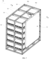
- FIG. 7 is a perspective view of a battery pack 30 according to an embodiment of the present disclosure
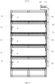
- FIG. 8 is a schematic diagram of the battery pack 30 shown in FIG. 8
- FIG. 9 is a cross-sectional view of the battery pack 30 shown in FIG. 7 , taken along a line F3-F3.
- the battery pack 30 in the present embodiment includes a battery management unit 31 and the battery module in any of the above embodiments. The present embodiment will be illustrated by taking the battery module 20 described in the above as an example.
- the battery management unit 31 is electrically connected to the pressure relief mechanism 11a, the cell 12, and the first detection unit 13. The battery management unit 31 determines, based on the detection result of the first detection unit 13, whether the cell has the thermal runaway. When the thermal runaway occurs, the battery management unit 31 controls the pressure relief mechanism 11a to expose the pressure relief port 103.
- the battery management unit 31 is electrically connected to the temperature detector 131 and the air detector 132 of the first detection unit 13.
- a plurality of battery modules 10 are arranged.
- the battery management unit 31 is electrically connected to the pressure relief mechanism 11a, the cell 12, and the first detection unit 13 of each battery module 10 of the plurality of battery modules 10, such that the first detection unit 13 of each battery module 10 performs detection independently.
- each of the battery modules 10 individually discharges the air and intakes the air. Therefore, when one cell has thermal runaway, the thermal runaway is prevented from spreading to any other cell 12 that does not have thermal runaway.
- the air discharging member 211 of the air discharging unit 21 defines a plurality of second air inlets 202 that are communicated with the air discharging channel 201. In this way, air inside the receiving spaces 101 of the plurality of battery modules 10 are discharged through the plurality of second air inlets 202 into the air discharging channel 201 to be further discharged out of the air outlet 203.
- the battery pack 30 in the present embodiment further includes a battery rack 32, defining a battery compartment 301.
- the housing 11 is received in the battery compartment 301. That is, the battery module 10 is received in the battery compartment 301.
- a plurality of the battery compartments 301 are defined, and each battery module 10 is received in a respective one of the plurality of battery compartments 301.
- the battery pack 30 in the present embodiment further includes an alarm 23.
- the battery management unit 31 is electrically connected to the alarm 23 to enable the battery management unit 31 to control, in response to determining that the cell 12 has the thermal runaway, the alarm 23 to give an alarm to alert the staff.
- the battery module includes the housing, the cell, and the first detection unit.
- the housing defines the receiving space, the pressure relief port communicated with the receiving space, and the first air inlet communicated with the receiving space.
- the pressure relief mechanism is arranged in the pressure relief port, and the air intaking mechanism is arranged in the first air inlet.
- the cell is received in the receiving space.
- the first detection unit is mounted on the housing and is configured to detect the predetermined object.
- the first detection unit is electrically connected to the pressure relief mechanism.
- the first detection unit in response to detecting thermal runaway of the cell, the pressure relief mechanism is opened to expose the pressure relief port.
- the air intaking mechanism is opened to expose the first air inlet.
- the first detection unit proactively detects the predetermined object.
- air is released actively.
- the active air releasing in the present disclosure avoids a situation in which, even though the cell has the thermal runaway, the internal pressure of the housing does not flush to open the pressure relief valve, such that failure of releasing the internal pressure of the housing is prevented.
- the air intaking mechanism is opened to expose the first air inlet, such that external air may enter the receiving space, further alleviating the thermal runaway of the cell.
Landscapes
- Chemical & Material Sciences (AREA)
- Chemical Kinetics & Catalysis (AREA)
- Electrochemistry (AREA)
- General Chemical & Material Sciences (AREA)
- Engineering & Computer Science (AREA)
- General Engineering & Computer Science (AREA)
- Manufacturing & Machinery (AREA)
- Mechanical Engineering (AREA)
- Microelectronics & Electronic Packaging (AREA)
- Battery Mounting, Suspending (AREA)
Abstract
A battery module includes: a housing (11), a cell (12), and a first detection unit (13). The housing defines a receiving space (101), a pressure relief port (102) communicated with the receiving space, and a first air inlet (103) communicated with the receiving space. A pressure relief mechanism (11a) is arranged in the pressure relief port, an air intaking mechanism (11b) is arranged in the first air inlet. The cell is received in the receiving space. The first detection unit is mounted on the housing and configured to detect a predetermined object. The first detection unit is electrically connected to the pressure relief mechanism. When the cell has thermal runaway, the pressure relief mechanism exposes the pressure relief port. When a pressure in the receiving space is less than or equal to a pressure threshold, the air intaking mechanism exposes the first air inlet.
Description
- The present disclosure relates to the field of batteries, and in particular to a battery module and a battery pack.
- As the new energy technology develops increasingly quickly, the battery module has been widely used in various new-energy vehicles and energy storage power stations. When the battery module is in use, if a short circuit occurs or the battery module is over-charged, a large amount of heat may be accumulated inside the battery module, such that thermal runaway may be caused, resulting in an internal pressure of the battery module being excessively high to cause fire or even explosion.
- In the art, a pressure relief valve is mounted on the battery module. When the internal pressure of the battery module is excessively high, the pressure relief valve is flushed to be open to release the internal pressure of the battery module, i.e., a passive resealing method is achieved. For the passive resealing method, in some cases, the pressure relief valve may be unable to be flushed to be open, such that the internal pressure of the battery module cannot be released.
- The present disclosure provides a battery module and a battery pack, to proactively discharge the air. A situation in which, even though thermal runaway of the cell occurs, the internal pressure of the housing does not flush to open the pressure relief valve, may be avoided.
- In a first aspect, a battery module is provided and includes: a housing, a cell, and a first detection unit. The housing defines a receiving space, a pressure relief port communicated with the receiving space, and a first air inlet communicated with the receiving space. A pressure relief mechanism is arranged in the pressure relief port, an air intaking mechanism is arranged in the first air inlet. The cell is received in the receiving space. The first detection unit is mounted on the housing and configured to detect a predetermined object. The first detection unit is electrically connected to the pressure relief mechanism; in response to the first detection unit detecting that the cell has thermal runaway, the pressure relief mechanism exposes the pressure relief port; in response to the first detection unit detecting that a pressure in the receiving space is less than or equal to a pressure threshold, the air intaking mechanism exposes the first air inlet.
- In a second aspect, a battery pack is provided and includes a battery management unit and the battery module as descried in the above. The battery management unit is electrically connected to the pressure relief mechanism, the cell, and the first detection unit.
- According to the present disclosure, the battery module includes a housing, a cell, and a first detection unit. The housing defines a receiving space, a pressure relief port communicated with the receiving space, and a first air inlet communicated with the receiving space. A pressure relief mechanism is arranged in the pressure relief port, and an air intaking mechanism is arranged in the first air inlet. The cell is received in the receiving space. The first detection unit is mounted on the housing and is configured to detect a predetermined object. The first detection unit is electrically connected to the pressure relief mechanism. The first detection unit, in response to detecting thermal runaway of the cell, the pressure relief mechanism is opened to expose the pressure relief port. In response to a pressure inside the receiving space being less than or equal to a pressure threshold, the air intaking mechanism is opened to expose the first air inlet. On the one hand, the first detection unit proactively detects the predetermined object. When the cell has thermal runaway, air is released actively. Compared to the passive air releasing method in the art, the active air releasing in the present disclosure avoids a situation in which, even though the cell has the thermal runaway, the internal pressure of the housing does not flush to open the pressure relief valve, such that failure of releasing the internal pressure of the housing is prevented. On the other hand, when the pressure inside the receiving space is less than or equal to the pressure threshold, the air intaking mechanism is opened to expose the first air inlet, such that external air may enter the receiving space, further alleviating the thermal runaway of the cell.
- In order to more clearly illustrate the technical solutions in the embodiments of the present disclosure, accompanying drawings for describing the embodiments will be introduced briefly in the following. Obviously, the following described accompanying drawings are only some of the embodiments of the present disclosure, any ordinary skilled person in the art may obtain other accompanying drawings based on the following drawings without any creative work.
-
FIG. 1 is a perspective view of a battery module according to an embodiment of the present disclosure. -
FIG. 2 is an exploded view of the battery module shown inFIG. 1 . -
FIG. 3 is a cross-sectional view of a housing and a pressure relief valve shown inFIG. 1 , taken along a line F1-F1. -
FIG. 4 is a cross-sectional view of the housing shown inFIG. 3 . -
FIG. 5 is a perspective view of the battery module according to another embodiment of the present disclosure. -
FIG. 6 is a cross-sectional view of the battery module shown inFIG. 5 , taken along a line F2-F2. -
FIG. 7 is a perspective view of a battery pack according to an embodiment of the present disclosure. -
FIG. 8 is a schematic diagram of the battery pack shown inFIG. 8 . -
FIG. 9 is a cross-sectional view of the battery pack shown inFIG. 7 , taken along a line F3-F3. - The terms "first", "second", and "third" in the present disclosure are used for descriptive purposes only and shall not be interpreted as indicating or implying relative importance or implicitly specifying the number of indicated technical features. Therefore, a feature defined by the "first", the "second", the "third" may explicitly or implicitly include at least one such feature. In the description of the present disclosure, "plurality" means at least two, such as two, three, and so on, unless otherwise expressly and specifically limited. Furthermore, the terms "include", "have", and any variations thereof, are intended to cover non-exclusive inclusion. A process, a method, a system, a product or an apparatus including a series of steps or units is not limited to the listed steps or units, but may further include steps or units that are not listed or steps or units that are inherently included in the process, the method, the system, the product or the apparatus.
- Particular features, structures, or properties described in an embodiment may be included in at least one embodiment of the present disclosure.
- As shown in
FIGS. 1 and2 ,FIG. 1 is a perspective view of abattery module 10 according to an embodiment of the present disclosure, andFIG. 2 is an exploded view of thebattery module 10 inFIG. 1 . Thebattery module 10 in the present embodiment includes ahousing 11, acell 12, and afirst detection unit 13. - As shown in
FIGS. 3 and4 ,FIG. 3 is a cross-sectional view of the housing 11and apressure relief mechanism 11a shown inFIG. 1 , taken along a line F1-F1, andFIG. 4 is a cross-sectional view of thehousing 11 shown inFIG. 3 . Thehousing 11 defines areceiving space 101, apressure relief port 102, and afirst air inlet 103. Thepressure relief port 102 and thefirst air inlet 103 are communicated with thereceiving space 101. Thecell 12 is received in thereceiving space 101. In practice, a plurality ofcells 12 may be arranged, and the plurality ofcells 12 are arranged in thereceiving space 101 in a bus manner. - The
pressure relief mechanism 11a is arranged in thepressure relief port 102, and anair intaking mechanism 11b is arranged in thefirst air inlet 103. - As shown in
FIGS. 2, 3 , and4 , thefirst detection unit 13 is mounted on thehousing 11 and is configured to detect a predetermined object. Thefirst detection unit 13 is electrically connected to thepressure relief mechanism 11a. When thefirst detection unit 13 detects that thecell 12 has thermal runaway, thepressure relief mechanism 11a is opened to expose thepressure relief port 102 to release the internal pressure of thehousing 11. In this way, a fire or even an explosion, caused by the internal pressure of thehousing 11 being excessively high, may be avoided. In the present disclosure, thefirst detection unit 13 proactively detects the predetermined object, such that when the cell has thermal runaway, an air inside the receiving space is released actively. Compared to the passive air releasing method in the art, the active air releasing in the present disclosure avoids a situation in which, even though thecell 12 has the thermal runaway, the internal pressure of thehousing 11 does not flush to open the pressure relief valve, such that failure of releasing the internal pressure of thehousing 11 is prevented. - Further, when the pressure inside the
receiving space 101 is less than or equal to the pressure threshold, theair intaking mechanism 11b is opened to expose thefirst air inlet 103, such that the external air is allowed to enter thereceiving space 101 to further alleviate the thermal runaway of thecell 12. It is understood that a specific value of the pressure threshold can be determined according to the actual needs, which will not be limited herein. - In some embodiments, in practice, the
pressure relief mechanism 11a may be a solenoid valve. When it is determined that thecell 12 has thermal runaway, the solenoid valve is controlled to expose thepressure relief port 102. Theair intaking mechanism 11b may be a pressure valve or the solenoid valve. For example, when the pressure inside the receivingspace 101 is less than or equal to the pressure threshold, an external pressure out of thehousing 11 is greater than the internal pressure of thehousing 11. In this case, the external air automatically rushes to open the pressure valve to enter thehousing 11. - In some embodiments, the
pressure relief port 102 and thefirst air inlet 103 are located at opposite sides of thehousing 11, such that a flowing direction of discharging the air out of the housing is the same as a flowing direction of intaking the air into the housing, and stability of the flowing during the discharging process and the intaking process may be improved. - In an application scenario, the
first detection unit 13 includes atemperature detector 131 configured to detect a temperature of thecell 12. When the temperature of thecell 12 is greater than or equal to a temperature threshold, thepressure relief mechanism 11a is opened to expose thepressure relief port 102. That is, in the present application scenario, the above-described predetermined object is thecell 12, and a detection result of thefirst detection unit 13 is the temperature of thecell 12. In this way, heat gathering caused by the thermal runaway of thecell 12 is avoided, such that a fire or an explosion caused by the internal pressure of thehousing 11 being excessively high may be avoided. - It is understood that, in practice, a location where the
temperature detector 131 is mounted may be determined according to the actual need, and the temperature threshold may also be determined according to the actual need, which will not be limited herein. For example, thetemperature detector 131 may be mounted on thehousing 11, and the temperature threshold may be greater than or equal to 75°C. - In another application scenario, the
first detection unit 13 includes anair detector 132, configured to detect composition of the air inside the receivingspace 101. When the composition inside the receivingspace 101 contains a thermal-runaway gas, thepressure relief mechanism 11a is opened to expose thepressure relief port 102. That is, in the present application scenario, the above-described predetermined object is the air inside the receivingspace 101, and a detection result of thefirst detection unit 13 is the composition inside the receivingspace 101. In this way, a personnel may be protected from being poisoned by any toxic air generated during the thermal runaway of thecell 12, and a fire or an explosion can be prevented. - It is understood that, in practice, a location where the
air detector 132 is mounted can be determined according to the actual need, and the composition in the receivingspace 101 that is to be detected is also determined according to the actual need, which will not be limited herein. For example, theair detector 132 may be mounted on thehousing 11, and the to-be-detected composition in the receivingspace 101 may be at least one of hydrogen, carbon monoxide, methane, and so on. - In the present embodiment, the
first detection unit 13 takes thetemperature detector 131 and theair detector 132 to perform detection. When the temperature of thecell 12 is greater than or equal to the temperature threshold value and the composition in the receivingspace 101 contains the thermal-runaway gas, thefirst detection unit 13 determines that thecell 12 has the thermal runaway and controls thepressure relief mechanism 11a to expose thepressure relief port 102. In this way, accuracy of detecting the thermal runaway of thecell 12 is improved. - In some embodiments, the
battery module 10 in the present embodiment further includes a second detection unit (not shown in the drawing) configured to detect a pressure inside the receivingspace 101. For example, theair intaking mechanism 11b may be the solenoid valve. When the second detection unit detects that the pressure inside the receivingspace 101 is less than or equal to the pressure threshold, the second detection unit controls the solenoid valve to expose thefirst inlet 103. In this way, the pressure inside the receivingspace 101 is detected proactively. - It is understood that, in practice, a location where the second detection unit is mounted may be determined according to the actual need. For example, the second detection unit may be mounted on the
housing 11. - As shown in
FIG. 5, FIG. 5 is a perspective view of thebattery module 20 according to another embodiment of the present disclosure, andFIG. 6 is a cross-sectional view of thebattery module 20 shown inFIG. 5 , taken along a line F2-F2. Thebattery module 20 in the present embodiment further includes anair discharging unit 21. The other structures of thebattery module 20 in the present embodiment are the same as those of thebattery module 10 in the above-described embodiment and will not be repeatedly described herein. - The
air discharging unit 21 is communicated with thepressure relief port 102 when thepressure relief mechanism 11a exposes thepressure relief port 102, such that the air in the receivingspace 101 is discharged, and an efficiency of discharging the air from the receivingspace 101 is improved. - . Further, the
air discharging unit 21 includes anair discharging member 211 and anair discharging mechanism 212. Theair discharging member 211 defines anair discharging channel 201, asecond air inlet 202 communicated with theair discharging channel 201, and anair outlet 203 communicated with theair discharging channel 201. When thepressure relief mechanism 11a exposes thepressure relief port 102, thesecond air inlet 202 is communicated with thepressure relief port 102. Theair discharging mechanism 212 is disposed in theair outlet 203, such that the air in the receivingspace 101 is discharged by flowing from thepressure relief port 102 and thesecond air inlet 202 successively to enter theair discharging channel 201, and subsequently, the air is discharged from theair outlet 203 by theair discharging mechanism 212. - In practice, the
air discharging mechanism 212 may be selected a fan. - As shown in
FIG. 7 ,FIG. 8 , andFIG. 9 ,FIG. 7 is a perspective view of abattery pack 30 according to an embodiment of the present disclosure,FIG. 8 is a schematic diagram of thebattery pack 30 shown inFIG. 8 , andFIG. 9 is a cross-sectional view of thebattery pack 30 shown inFIG. 7 , taken along a line F3-F3. Thebattery pack 30 in the present embodiment includes a battery management unit 31 and the battery module in any of the above embodiments. The present embodiment will be illustrated by taking thebattery module 20 described in the above as an example. - The battery management unit 31 is electrically connected to the
pressure relief mechanism 11a, thecell 12, and thefirst detection unit 13. The battery management unit 31 determines, based on the detection result of thefirst detection unit 13, whether the cell has the thermal runaway. When the thermal runaway occurs, the battery management unit 31 controls thepressure relief mechanism 11a to expose thepressure relief port 103. - It is understood that, in the present implementation, the battery management unit 31 is electrically connected to the
temperature detector 131 and theair detector 132 of thefirst detection unit 13. - Further, in the present embodiment, a plurality of
battery modules 10 are arranged. The battery management unit 31 is electrically connected to thepressure relief mechanism 11a, thecell 12, and thefirst detection unit 13 of eachbattery module 10 of the plurality ofbattery modules 10, such that thefirst detection unit 13 of eachbattery module 10 performs detection independently. In this way, when the cells in the plurality ofbattery modules 10 have thermal runaway, each of thebattery modules 10 individually discharges the air and intakes the air. Therefore, when one cell has thermal runaway, the thermal runaway is prevented from spreading to anyother cell 12 that does not have thermal runaway. - In the present embodiment, the
air discharging member 211 of theair discharging unit 21 defines a plurality ofsecond air inlets 202 that are communicated with theair discharging channel 201. In this way, air inside the receivingspaces 101 of the plurality ofbattery modules 10 are discharged through the plurality ofsecond air inlets 202 into theair discharging channel 201 to be further discharged out of theair outlet 203. - Further, the
battery pack 30 in the present embodiment further includes abattery rack 32, defining abattery compartment 301. Thehousing 11 is received in thebattery compartment 301. That is, thebattery module 10 is received in thebattery compartment 301. In the present embodiment, a plurality of the battery compartments 301 are defined, and eachbattery module 10 is received in a respective one of the plurality of battery compartments 301. - Further, the
battery pack 30 in the present embodiment further includes an alarm 23. The battery management unit 31 is electrically connected to the alarm 23 to enable the battery management unit 31 to control, in response to determining that thecell 12 has the thermal runaway, the alarm 23 to give an alarm to alert the staff. - According to the present disclosure, the battery module includes the housing, the cell, and the first detection unit. The housing defines the receiving space, the pressure relief port communicated with the receiving space, and the first air inlet communicated with the receiving space. The pressure relief mechanism is arranged in the pressure relief port, and the air intaking mechanism is arranged in the first air inlet. The cell is received in the receiving space. The first detection unit is mounted on the housing and is configured to detect the predetermined object. The first detection unit is electrically connected to the pressure relief mechanism. The first detection unit, in response to detecting thermal runaway of the cell, the pressure relief mechanism is opened to expose the pressure relief port. In response to a pressure inside the receiving space being less than or equal to a pressure threshold, the air intaking mechanism is opened to expose the first air inlet. On the one hand, the first detection unit proactively detects the predetermined object. When the cell has thermal runaway, air is released actively. Compared to the passive air releasing method in the art, the active air releasing in the present disclosure avoids a situation in which, even though the cell has the thermal runaway, the internal pressure of the housing does not flush to open the pressure relief valve, such that failure of releasing the internal pressure of the housing is prevented. On the other hand, when the pressure inside the receiving space is less than or equal to the pressure threshold, the air intaking mechanism is opened to expose the first air inlet, such that external air may enter the receiving space, further alleviating the thermal runaway of the cell.
- The above describes only a part of the embodiments of the present disclosure, and does not limit the scope of the present disclosure. Any equivalent device or equivalent process transformation performed based on the specification and the accompanying drawings of the present disclosure, applied directly or indirectly in other related technical fields, shall be included in the scope of the present disclosure.
Claims (10)
- A battery module, comprising:a housing (11), defining a receiving space (101), a pressure relief port (102) communicated with the receiving space (101), and a first air inlet (103) communicated with the receiving space (101), wherein a pressure relief mechanism (11a) is arranged in the pressure relief port (102), an air intaking mechanism (11b) is arranged in the first air inlet (103);a cell (12), received in the receiving space (101);a first detection unit (13), mounted on the housing (11) and configured to detect a predetermined object, wherein the first detection unit (13) is electrically connected to the pressure relief mechanism (11a); in response to the first detection unit (13) detecting that the cell (12) has thermal runaway, the pressure relief mechanism (11a) exposes the pressure relief port (102); in response to the first detection unit (13) detecting that a pressure in the receiving space (101) is less than or equal to a pressure threshold, the air intaking mechanism (11b) exposes the first air inlet (103).
- The battery module according to claim 1, wherein, the first detection unit (13) includes a temperature detector (131), the predetermined object is the cell (12), the temperature detector (131) is configured to detect a temperature of the cell (12); and in response to the temperature of the cell (12) being greater than or equal to a temperature threshold, the pressure relief mechanism (11a) exposes the pressure relief port (102).
- The battery module according to claim 1, wherein, the first detection unit (13) includes an air detector (132), the predetermined object is air in the receiving space (101), the air detector (132) is configured to detect composition of the air in the receiving space (101); and in response to the composition of the air in the receiving space (101) including a thermal-runaway gas, the pressure relief mechanism (11a) exposes the pressure relief port (102).
- The battery module according to claim 1, wherein, the battery module further comprises an air discharging unit (21), in response to the pressure relief mechanism (11a) exposing the pressure relief port (102), the air discharging unit (21) is communicated with the pressure relief port (102) to discharge the air in the receiving space (101).
- The battery module according to claim 4, wherein, the air discharging unit (21) comprises an air discharging member (211) and an air discharging mechanism (212); the air discharging member (211) defines an air discharging channel (201), a second air inlet (202) communicated with the air discharging channel (201), and an air outlet (203) communicated with the air discharging channel (201); in response to the pressure relief mechanism (11a) exposing the pressure relief port (102), the second air inlet (202) is communicated with the pressure relief port (102); and the air discharging mechanism (212) is disposed in the air outlet (203).
- The battery module according to claim 1, wherein, the battery module further comprises a second detection unit, the second detection unit is configured to detect the pressure inside the receiving space (101).
- The battery module according to claim 1, wherein, the pressure relief port (102) and the first air inlet (103) are disposed at opposite sides of the housing (11).
- A battery pack, comprising a battery management unit (31) and the battery module according to any one of claims 1 to 7, the battery management unit (31) being electrically connected to the pressure relief mechanism (11a), the cell (12), and the first detection unit (13).
- The battery pack according to claim 8, wherein, the battery pack further comprises a battery rack (32), the battery rack (32) defines a battery compartment (301), and the housing (11) is received in the battery compartment (301).
- The battery pack according to claim 8, wherein, the battery pack further comprises an alarm (23), the battery management unit (31) is electrically connected to the alarm (23).
Applications Claiming Priority (1)
| Application Number | Priority Date | Filing Date | Title |
|---|---|---|---|
| CN202323527750.8U CN222214389U (en) | 2023-12-22 | 2023-12-22 | Battery module and battery pack |
Publications (1)
| Publication Number | Publication Date |
|---|---|
| EP4576323A1 true EP4576323A1 (en) | 2025-06-25 |
Family
ID=92172069
Family Applications (1)
| Application Number | Title | Priority Date | Filing Date |
|---|---|---|---|
| EP24192107.1A Pending EP4576323A1 (en) | 2023-12-22 | 2024-07-31 | Battery module and battery pack |
Country Status (4)
| Country | Link |
|---|---|
| US (1) | US20250210795A1 (en) |
| EP (1) | EP4576323A1 (en) |
| CN (1) | CN222214389U (en) |
| WO (1) | WO2025129827A1 (en) |
Citations (7)
| Publication number | Priority date | Publication date | Assignee | Title |
|---|---|---|---|---|
| US6372378B1 (en) * | 2000-06-30 | 2002-04-16 | The United States Of America As Represented By The Secretary Of The Army | Battery casing for armored vehicles |
| US20120040212A1 (en) * | 2010-08-10 | 2012-02-16 | Tesla Motors, Inc. | Hazard Mitigation Within a Battery Pack Using Metal-Air Cells |
| CN110739424A (en) * | 2019-10-28 | 2020-01-31 | 广州小鹏汽车科技有限公司 | A battery box and a battery box thermal runaway monitoring method |
| EP3840083A1 (en) * | 2019-12-20 | 2021-06-23 | Samsung SDI Co., Ltd. | Thermal runaway detection system and battery system |
| CN114156568A (en) * | 2022-02-07 | 2022-03-08 | 华北电力大学 | Energy storage container battery cabinet control method and energy storage container |
| US20230026302A1 (en) * | 2021-07-20 | 2023-01-26 | Rivian Ip Holdings, Llc | Battery pack venting |
| US20230307781A1 (en) * | 2022-01-27 | 2023-09-28 | Huawei Digital Power Technologies Co., Ltd. | Battery Apparatus, Method for Controlling Battery Apparatus to Exhaust Gas, and Energy Storage Device |
Family Cites Families (5)
| Publication number | Priority date | Publication date | Assignee | Title |
|---|---|---|---|---|
| CN210070530U (en) * | 2019-02-28 | 2020-02-14 | 北京新能源汽车股份有限公司 | Dehumidification system of power battery |
| CN113948813B (en) * | 2020-07-17 | 2024-02-06 | 上海汽车集团股份有限公司 | An explosion-proof control system and explosion-proof control method for power batteries |
| CN215816098U (en) * | 2021-06-04 | 2022-02-11 | 恒大新能源技术(深圳)有限公司 | Battery pack thermal runaway protection system and battery pack |
| CN115911622B (en) * | 2022-09-09 | 2024-03-12 | 江苏正力新能电池技术有限公司 | Battery pack, power utilization device and thermal runaway detection and control method of battery pack |
| CN115548477A (en) * | 2022-10-10 | 2022-12-30 | 中国久远高新技术装备有限公司 | Energy storage battery with explosion-proof function |
-
2023
- 2023-12-22 CN CN202323527750.8U patent/CN222214389U/en active Active
-
2024
- 2024-03-16 WO PCT/CN2024/082067 patent/WO2025129827A1/en active Pending
- 2024-07-31 EP EP24192107.1A patent/EP4576323A1/en active Pending
- 2024-08-08 US US18/797,534 patent/US20250210795A1/en active Pending
Patent Citations (7)
| Publication number | Priority date | Publication date | Assignee | Title |
|---|---|---|---|---|
| US6372378B1 (en) * | 2000-06-30 | 2002-04-16 | The United States Of America As Represented By The Secretary Of The Army | Battery casing for armored vehicles |
| US20120040212A1 (en) * | 2010-08-10 | 2012-02-16 | Tesla Motors, Inc. | Hazard Mitigation Within a Battery Pack Using Metal-Air Cells |
| CN110739424A (en) * | 2019-10-28 | 2020-01-31 | 广州小鹏汽车科技有限公司 | A battery box and a battery box thermal runaway monitoring method |
| EP3840083A1 (en) * | 2019-12-20 | 2021-06-23 | Samsung SDI Co., Ltd. | Thermal runaway detection system and battery system |
| US20230026302A1 (en) * | 2021-07-20 | 2023-01-26 | Rivian Ip Holdings, Llc | Battery pack venting |
| US20230307781A1 (en) * | 2022-01-27 | 2023-09-28 | Huawei Digital Power Technologies Co., Ltd. | Battery Apparatus, Method for Controlling Battery Apparatus to Exhaust Gas, and Energy Storage Device |
| CN114156568A (en) * | 2022-02-07 | 2022-03-08 | 华北电力大学 | Energy storage container battery cabinet control method and energy storage container |
Also Published As
| Publication number | Publication date |
|---|---|
| WO2025129827A1 (en) | 2025-06-26 |
| US20250210795A1 (en) | 2025-06-26 |
| CN222214389U (en) | 2024-12-20 |
Similar Documents
| Publication | Publication Date | Title |
|---|---|---|
| CN110313080B (en) | Battery pack including fire suppression system | |
| US11626626B2 (en) | Lithium-ion battery impending failure detection | |
| JP7506157B2 (en) | Thermal runaway detection method and battery management system | |
| US7488546B2 (en) | Medium- or large-sized battery pack having safety device | |
| EP3333932A1 (en) | Battery system | |
| CN114824537B (en) | Lithium iron phosphate battery thermal runaway monitoring system based on information fusion | |
| US20240170747A1 (en) | Battery fire detection device and method, and energy storage system | |
| KR102708920B1 (en) | System and Method for Preventing Multipurpose modular Battery Fire | |
| KR20260047613A (en) | Battery and eletric apparatus | |
| CN116345012B (en) | Thermal safety management system for energy storage battery | |
| EP4322305A1 (en) | Battery system, and ess and vehicle comprising same | |
| CN115347297B (en) | A kind of detachable battery core module and ladder utilization method | |
| KR102718427B1 (en) | A battery module having a guide wing to induce fire extinguishing agent into a battery cell unit and battery rack comprising the same and energy storage system comprising the same | |
| EP4576323A1 (en) | Battery module and battery pack | |
| KR102931026B1 (en) | System for early fire, thermal runaway detection of ESS battery modules | |
| EP3975316B1 (en) | Extinguishing battery thermal runaway | |
| KR20240131184A (en) | Battery pack and vehicle including same | |
| CN114778773A (en) | Fire very early warning equipment, fire very early warning control system and fire very early warning control method for energy storage system | |
| CN219917417U (en) | Battery and electric equipment | |
| US12083931B2 (en) | Fuel cell system and air vehicle | |
| CN216161895U (en) | Diversion module, battery pack and vehicle | |
| EP4708449A1 (en) | Battery box with structure securing fire safety and enabling multi-layer stacking | |
| CN115663313B (en) | Integrated power distribution system and battery pack | |
| JPS58166669A (en) | Fuel cell | |
| US20250239741A1 (en) | Battery module and energy storage system including the same |
Legal Events
| Date | Code | Title | Description |
|---|---|---|---|
| PUAI | Public reference made under article 153(3) epc to a published international application that has entered the european phase |
Free format text: ORIGINAL CODE: 0009012 |
|
| STAA | Information on the status of an ep patent application or granted ep patent |
Free format text: STATUS: REQUEST FOR EXAMINATION WAS MADE |
|
| 17P | Request for examination filed |
Effective date: 20240902 |
|
| AK | Designated contracting states |
Kind code of ref document: A1 Designated state(s): AL AT BE BG CH CY CZ DE DK EE ES FI FR GB GR HR HU IE IS IT LI LT LU LV MC ME MK MT NL NO PL PT RO RS SE SI SK SM TR |