EP4576310A1 - Electrode assembly and secondary battery comprising same - Google Patents
Electrode assembly and secondary battery comprising same Download PDFInfo
- Publication number
- EP4576310A1 EP4576310A1 EP23855192.3A EP23855192A EP4576310A1 EP 4576310 A1 EP4576310 A1 EP 4576310A1 EP 23855192 A EP23855192 A EP 23855192A EP 4576310 A1 EP4576310 A1 EP 4576310A1
- Authority
- EP
- European Patent Office
- Prior art keywords
- protective member
- electrode
- separator
- electrode assembly
- winding
- Prior art date
- Legal status (The legal status is an assumption and is not a legal conclusion. Google has not performed a legal analysis and makes no representation as to the accuracy of the status listed.)
- Pending
Links
Images


Classifications
-
- H—ELECTRICITY
- H01—ELECTRIC ELEMENTS
- H01M—PROCESSES OR MEANS, e.g. BATTERIES, FOR THE DIRECT CONVERSION OF CHEMICAL ENERGY INTO ELECTRICAL ENERGY
- H01M50/00—Constructional details or processes of manufacture of the non-active parts of electrochemical cells other than fuel cells, e.g. hybrid cells
- H01M50/40—Separators; Membranes; Diaphragms; Spacing elements inside cells
- H01M50/471—Spacing elements inside cells other than separators, membranes or diaphragms; Manufacturing processes thereof
- H01M50/474—Spacing elements inside cells other than separators, membranes or diaphragms; Manufacturing processes thereof characterised by their position inside the cells
-
- H—ELECTRICITY
- H01—ELECTRIC ELEMENTS
- H01M—PROCESSES OR MEANS, e.g. BATTERIES, FOR THE DIRECT CONVERSION OF CHEMICAL ENERGY INTO ELECTRICAL ENERGY
- H01M10/00—Secondary cells; Manufacture thereof
- H01M10/04—Construction or manufacture in general
- H01M10/0431—Cells with wound or folded electrodes
-
- H—ELECTRICITY
- H01—ELECTRIC ELEMENTS
- H01M—PROCESSES OR MEANS, e.g. BATTERIES, FOR THE DIRECT CONVERSION OF CHEMICAL ENERGY INTO ELECTRICAL ENERGY
- H01M10/00—Secondary cells; Manufacture thereof
- H01M10/42—Methods or arrangements for servicing or maintenance of secondary cells or secondary half-cells
- H01M10/4235—Safety or regulating additives or arrangements in electrodes, separators or electrolyte
-
- H—ELECTRICITY
- H01—ELECTRIC ELEMENTS
- H01M—PROCESSES OR MEANS, e.g. BATTERIES, FOR THE DIRECT CONVERSION OF CHEMICAL ENERGY INTO ELECTRICAL ENERGY
- H01M50/00—Constructional details or processes of manufacture of the non-active parts of electrochemical cells other than fuel cells, e.g. hybrid cells
- H01M50/40—Separators; Membranes; Diaphragms; Spacing elements inside cells
- H01M50/409—Separators, membranes or diaphragms characterised by the material
- H01M50/449—Separators, membranes or diaphragms characterised by the material having a layered structure
-
- H—ELECTRICITY
- H01—ELECTRIC ELEMENTS
- H01M—PROCESSES OR MEANS, e.g. BATTERIES, FOR THE DIRECT CONVERSION OF CHEMICAL ENERGY INTO ELECTRICAL ENERGY
- H01M50/00—Constructional details or processes of manufacture of the non-active parts of electrochemical cells other than fuel cells, e.g. hybrid cells
- H01M50/50—Current conducting connections for cells or batteries
- H01M50/572—Means for preventing undesired use or discharge
- H01M50/584—Means for preventing undesired use or discharge for preventing incorrect connections inside or outside the batteries
- H01M50/586—Means for preventing undesired use or discharge for preventing incorrect connections inside or outside the batteries inside the batteries, e.g. incorrect connections of electrodes
-
- H—ELECTRICITY
- H01—ELECTRIC ELEMENTS
- H01M—PROCESSES OR MEANS, e.g. BATTERIES, FOR THE DIRECT CONVERSION OF CHEMICAL ENERGY INTO ELECTRICAL ENERGY
- H01M10/00—Secondary cells; Manufacture thereof
- H01M10/05—Accumulators with non-aqueous electrolyte
- H01M10/058—Construction or manufacture
- H01M10/0587—Construction or manufacture of accumulators having only wound construction elements, i.e. wound positive electrodes, wound negative electrodes and wound separators
-
- Y—GENERAL TAGGING OF NEW TECHNOLOGICAL DEVELOPMENTS; GENERAL TAGGING OF CROSS-SECTIONAL TECHNOLOGIES SPANNING OVER SEVERAL SECTIONS OF THE IPC; TECHNICAL SUBJECTS COVERED BY FORMER USPC CROSS-REFERENCE ART COLLECTIONS [XRACs] AND DIGESTS
- Y02—TECHNOLOGIES OR APPLICATIONS FOR MITIGATION OR ADAPTATION AGAINST CLIMATE CHANGE
- Y02E—REDUCTION OF GREENHOUSE GAS [GHG] EMISSIONS, RELATED TO ENERGY GENERATION, TRANSMISSION OR DISTRIBUTION
- Y02E60/00—Enabling technologies; Technologies with a potential or indirect contribution to GHG emissions mitigation
- Y02E60/10—Energy storage using batteries
-
- Y—GENERAL TAGGING OF NEW TECHNOLOGICAL DEVELOPMENTS; GENERAL TAGGING OF CROSS-SECTIONAL TECHNOLOGIES SPANNING OVER SEVERAL SECTIONS OF THE IPC; TECHNICAL SUBJECTS COVERED BY FORMER USPC CROSS-REFERENCE ART COLLECTIONS [XRACs] AND DIGESTS
- Y02—TECHNOLOGIES OR APPLICATIONS FOR MITIGATION OR ADAPTATION AGAINST CLIMATE CHANGE
- Y02P—CLIMATE CHANGE MITIGATION TECHNOLOGIES IN THE PRODUCTION OR PROCESSING OF GOODS
- Y02P70/00—Climate change mitigation technologies in the production process for final industrial or consumer products
- Y02P70/50—Manufacturing or production processes characterised by the final manufactured product
Definitions
- the present invention relates to an electrode assembly and a device including the same, and more specifically, to an electrode assembly capable of improving safety and a secondary battery including the same.
- Rechargeable batteries are classified into coin type batteries, cylindrical type batteries, prismatic type batteries, and pouch type batteries according to a shape of a battery case.
- the electrode assembly mounted inside the battery case is a chargeable and dischargeable power generation device having a structure in which electrodes and separators are stacked.
- Embodiments of the present invention provide an electrode assembly capable of improving safety and a secondary battery including the same.
- the protective member may include: a first protective member disposed between the first separator and the edge portion at which the winding of the first electrode starts; and a second protective member disposed between the second separator and the edge portion at which the winding of the first electrode starts.
- a portion of each of the first protective member and the second protective member may be disposed to be in contact with each other between the first separator and the second separator.
- At least one of the first protective member or the second protective member may be disposed to wind the non-coating portion of the second electrode at least once.
- At least one of the first protective member or the second protective member may be wound at least once between the winding center of the electrode assembly and the edge portion at which the winding of the first electrode starts, and at least one of the first protective member or the second protective member may be wound at least once between a winding outer portion of the electrode assembly and the edge portion at which the winding of the first electrode starts.
- At least one of the first separator or the second separator may include a plurality of voids defined in the vicinity facing the protective member, and a portion of the protective member may be disposed in at least one void of the first separator and the second separator.
- the protective member may be made of a thermoplastic resin.
- the protective member may include a hot-melt adhesive sheet that is melted at a high temperature and returns to a solid state at a low temperature.
- the protective member may be attached to only one of the first separator and the second separator.
- a secondary battery according to an embodiment may include the above-described electrode assembly.
- the electrode assembly may include the protective member disposed between the edge portion at which the winding of the positive electrode starts and the separator.
- the protective member and the separator may prevent the cracks of the negative electrode at the portion that is in contact with the edge portion of the positive electrode to prevent the disconnection or the short circuit, thereby improving the safety of the secondary battery.
- the winding center of the electrode assembly may be easily maintained in its original shape through the protective member and the separator. Therefore, the internal short circuits may be prevented from occurring during the charge/discharge cycle of the secondary battery including the electrode assembly to ensure the safety.
- a secondary battery 10 may include an electrode assembly 100 and a battery case 180.
- the battery can 182 may be provided in a shape corresponding to that of the electrode assembly 100.
- the battery can 182 may be provided in a cylindrical shape so that the electrode assembly 100, which is provided in a jelly-roll shape, is accommodated.
- the cap assembly 181 may be mounted on the battery can 182 to cover the opened upper portion of the battery can 182 and be coupled to the battery can 182
- the cap assembly 181 may be provided by sequentially stacking a safety belt, a current blocking element, a positive temperature coefficient (PTC) element, and a top cap.
- the top cap is seated and coupled to the uppermost portion of the cap assembly 181 to transmit current generated in the secondary battery to the outside.
- the first electrode 110 may include a first collector 111 and a first active material layer 112 disposed on at least one of one surface and the other surface of the first collector 111.
- the first collector 111 may be made of aluminum foil.
- the first active material layer 112 may include, for example, lithium manganese oxide, lithium cobalt oxide, lithium nickel oxide, lithium iron phosphate, or a compound containing at least one of these and mixtures thereof.
- the second protective member 220 may be disposed in a solid form between the edge portion at which the winding of the first electrode 110 starts and the second separator 150 before the electrode assembly 100 is wound.
- the second protective member 220 may be provided on the second separator 140 in a width direction of the second separator 140.
- the second protective member 220 may be disposed parallel to at least one of the first electrode tab 171 and the second electrode tab 172 before the electrode assembly 100 is wound.
- At least one of the first protective member 210 or the second protective member 220 may include a thermoplastic resin.
- the first protective member 210 and the second protective member 220 may be made of the same or different thermoplastic resin materials.
- at least one of the first protective member 210 or the second protective member 220 may include a hot-melt adhesive sheet that is melted at a high temperature of 120 degrees to 140 degrees and returns to the solid state at a low temperature.
- FIG. 4a is an enlarged cross-sectional view illustrating an example of a portion adjacent to the winding center C of the electrode assembly according to the first embodiment of the present invention
- FIG. 4b is an enlarged cross-sectional view illustrating the other example of the portion adjacent to the winding center C of the electrode assembly according to the first embodiment of the present invention.
- the electrode assembly 100 may include a first electrode (or positive electrode) 110, a first separator 140, a second electrode (or negative electrode) 120, a second separator 150, and a protective member 200.
- the protective member 200 may be disposed in a space between each of the first separator 140 and the second separator 150 and the edge portion at which the winding of the first electrode 110 starts. After winding the electrode assembly 100, the protective member 200 may have a shape corresponding to at least a portion of the space between each of the first separator 140 and the second separator 150 and the edge portion at which the winding of the first electrode 110 starts.
- the protective member 200 may include a first protective member 210 and a second protective member 220.
- the first protective member 210 and the second protective member 220 may be melted in a first high-temperature manufacturing process after the electrode assembly 100 is wound. Since each of the molted first protective member 210 and second protective member 220 are in a liquid state, the first protective member 210 and the second protective member 220 may be introduced between the first separator 140 and the second separator 150 toward the winding center C and also may be introduced into the space between each of the first separator 140 and the second separator 150 and the first electrode 110. The melted first protective member 210 and second protective member 220 may be solidified again in a second low-temperature manufacturing process.
- first protective member 210 and the second protective member 220 may not only provided to be in contact with each other between the first separator 140 and the second separator 150, but also provided to be in contact with each other in a partial space between each of the first separator 140 and the second separator 150 and the edge portion at which the winding of the first electrode 110 starts.
- the first protective member 210 and the second protective member 220 may be provided to surround a side surface of the first active material layer 112 and a side surface of the first collector 111 of the first electrode 110, which is provided on the edge portion, at which the winding of the first electrode 110 starts.
- the first protective member 210 and the second protective member 220 may be provided to be spaced apart from each other on an area adjacent to the edge portion of the first electrode 110. At least one of the first protective member 210 or the second protective member 220 illustrated in FIG. 4a may be provided to cover at least a portion of the side surface of the first active material layer 112 except for the side surface of the first collector 111 facing the winding center C. At least one of the first protective member 210 or the second protective member 220 illustrated in FIG. 4a may be in non-contact with the side surface of the first collector 111 facing the winding center C and be in contact with the side surface of the first active material layer 112.
- the first protective member 210 and the second protective member 220 may be provided to be integrated with each other by being in contact with each other on the area adjacent to the edge portion of the first electrode 110. At least one of the first protective member 210 or the second protective member 220 illustrated in FIG. 4b may be provided to cover the side surface of the first collector 111 facing the winding center C and the side surface of the first active material layer 112. At least one of the first protective member 210 or the second protective member 220 illustrated in FIG. 4b may be in contact with the side surface of the first collector 111 facing the winding center C and the side surface of the first active material layer 112.
- the reform process may be a process in which the first separator 140 and/or the second separator 150, which are separated to the outside together with the core returns to the winding center C of the electrode assembly 100.
- FIG. 5a is a view illustrating a portion of a protective member disposed on a separator before the electrode assembly is wound according to the first embodiment of the present invention
- FIG. 5b is a view illustrating a portion of the protective member disposed on the separator of FIG. 5a after a reform process.
- the separator 160 illustrated in FIGS. 5a and 5b may be at least one of the first separator 140 or the second separator 150 illustrated in FIGS. 4a and 4b
- the protective member 200 illustrated in FIGS. 5a and 5b may be at least one of the first protective member 210 and the second protective member 220 illustrated in FIGS. 4a and 4b .
- the protective member 200 before winding the electrode assembly may have a first horizontal length LH1, a first vertical length LV1, and a first thickness T1 on the separator 160 as illustrated in FIG. 5a .
- the protective member 200 may be melted in a liquid state.
- the molted liquid protective member 200 may be expanded to an adjacent area and then be introduced into a void 161 of the separator 160 that is in contact with the protective member 200.
- the protective member 200 may be hardened and solidified in the second low-temperature manufacturing process.
- the protective member 200 may be solidified with a thinner thickness and a larger surface area than before the winding process.
- the protective member 200 after the first high-temperature manufacturing process may have a second horizontal length LH2 that is longer than the first horizontal length LH1, a second vertical length LV2 that is longer than the first vertical length LV1, and a second thickness T2 that is thinner than the first thickness T1.
- the void may not be formed in at least a portion of the separator 160 facing the electrode 130.
- the conductive material contained in the electrode 130 may be prevented from being introduced into the void of the separator 160.
- FIG. 6 is a cross-sectional view illustrating an unfolded state before an electrode assembly is wound according to a second embodiment of the present invention.
- FIG. 7 is a cross-sectional view illustrating a state after the electrode assembly of FIG. 6 is wound, and the first separator and the second separator illustrated in FIG. 6 are omitted.
- FIG. 8 is an enlarged cross-sectional view of a portion "D" adjacent to a central side of the electrode assembly in FIG. 7 .
- An electrode assembly according to the second embodiment of the present invention has the same components as the electrode assembly according to the first embodiment of the present invention illustrated in FIGS. 1 to 5b except for a protective member. Thus, detailed descriptions of the same components will follow the descriptions of FIGS. 2 to 5b .
- an electrode assembly according to the second embodiment of the present invention may include a first protective member 210 and a second protective member 220.
- At least one of the first protective member 210 or the second protective member 220 may be elongated toward the winding center C of the electrode assembly 100 from an area adjacent to the edge portion of the first electrode 110. At least one of the first protective member 210 or the second protective member 220 may be provided to overlap the second electrode tab 172 before the electrode assembly 100 is wound. For example, the first protective member 210 may be provided to overlap the second electrode tab 172 before the electrode assembly is wound.
- At least one of the first protective member 210 or the second protective member 220 may be wound at least once between the winding center C and the edge portion at which the winding of the first electrode 110 starts. At least one of the first protective member 210 or the second protective member 220 may be disposed near the winding center C at which a non-coating portion 123 constituted by a second collector 121 of the second electrode 120 is disposed. At least one of the first protective member 210 or the second protective member 220 may be disposed between the first separator 140 and the second separator 150, which are near the winding center C.
- the first protective member 210 and the second protective member 220 may be provided to surround the winding center C of the electrode assembly at least once.
- the non-coating portion 123 constituted by the second collector 121 of the second electrode 120 may be wound at least once.
- the winding center C of the electrode assembly may be easily maintained in its original shape through the highly rigid first separator 140 and second separator 150 near the center C, and the first protective member 210 and the second protective member 220. Therefore, the internal short circuits may be prevented from occurring during the charge/discharge cycle of the secondary battery including the electrode assembly to ensure the safety.
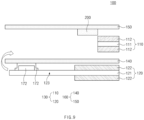
- FIG. 9 is a cross-sectional view of an electrode assembly according to a third embodiment of the present invention.
- FIG. 9 is a view illustrating a portion of the electrode assembly according to the third embodiment of the present invention to correspond to FIG. 3 .
- An electrode assembly according to the third embodiment of the present invention has the same components as the electrode assembly according to the first embodiment of the present invention illustrated in FIGS. 1 to 5b except for a protective member. Thus, detailed descriptions of the same components will follow the descriptions of FIGS. 2 to 5b .
- an electrode assembly according to the third embodiment of the present invention may be attached to only one of a first separator and a second separator.
- a protective member is illustrated to be attached only to the second separator, but the present invention is not limited thereto. That is, the protective member may be provided to be attached only to the first separator or may be provided to be attached only to the second separator. If necessary, the protective member may be attached to only one of the first separator and the second separator.
- the protective member may be attached to only one of the first separator and the second separator to prevent the material waste and the deteriorated production efficiency from occurring.
- the secondary battery including the above-described electrode assembly may be applied to various devices. It may be applied to transportation means such as electric bicycles, electric vehicles, hybrids, etc., but is not limited thereto and may be applied to various devices capable of using the battery module.
Landscapes
- Chemical & Material Sciences (AREA)
- Chemical Kinetics & Catalysis (AREA)
- Electrochemistry (AREA)
- General Chemical & Material Sciences (AREA)
- Engineering & Computer Science (AREA)
- Manufacturing & Machinery (AREA)
- Secondary Cells (AREA)
- Battery Electrode And Active Subsutance (AREA)
- Cell Separators (AREA)
- Connection Of Batteries Or Terminals (AREA)
Abstract
Description
- The present application claims the benefit of the priority of
Korean Patent Application Nos. 10-2022-0104376, filed on August 19, 2022 10-2023-0107156, filed on August 16, 2023 - The present invention relates to an electrode assembly and a device including the same, and more specifically, to an electrode assembly capable of improving safety and a secondary battery including the same.
- Recently, as demands for portable electronic products such as laptops, video cameras, and mobile phones have rapidly increased, and development of electric vehicles, energy storage batteries, robots, satellites, etc. is regularized, a lot of researches have been conducted on a secondary battery used as a driving power source.
- Rechargeable batteries are classified into coin type batteries, cylindrical type batteries, prismatic type batteries, and pouch type batteries according to a shape of a battery case. The electrode assembly mounted inside the battery case is a chargeable and dischargeable power generation device having a structure in which electrodes and separators are stacked.
- When a charge/discharge cycle of the secondary battery including such the electrode assembly is repeated, swelling of the electrode assembly may occur, and a winding center of the electrode assembly may be deformed. If the winding center of the electrode assembly is not maintained in its original shape and is deformed, an internal short circuit or disconnection may occur during the charge/discharge cycle to significantly deteriorate the safety.
- Embodiments of the present invention provide an electrode assembly capable of improving safety and a secondary battery including the same.
- The object of the present invention is not limited to the aforesaid, but other objects not described herein will be clearly understood by those skilled in the art from descriptions below.
- An electrode assembly according to an embodiment of the present invention may be provided by winding a first electrode, a first separator, a second electrode, and a second separator, and the electrode assembly may include a protective member disposed in a space between each of the first separator and the second separator and an edge portion, at which the winding of the first electrode starts, and having a shape corresponding to that of at least a portion of the space.
- According to an embodiment, the protective member may be disposed to surround the edge portion, at which the winding of the first electrode starts, at least once.
- According to an embodiment, the first electrode may include: a first collector; and a first active material layer disposed on the first collector, wherein the protective member may be configured to surround a side surface of the first collector and a side surface of the first active material layer, which are provided in the first electrode.
- According to an embodiment, the protective member may be in contact with the side surface of the first collector facing the winding center and the side surface of the first active material layer.
- According to an embodiment, the protective member may include: a first protective member disposed between the first separator and the edge portion at which the winding of the first electrode starts; and a second protective member disposed between the second separator and the edge portion at which the winding of the first electrode starts.
- According to an embodiment, a portion of each of the first protective member and the second protective member may be disposed to be in contact with each other between the first separator and the second separator.
- According to an embodiment, at least one of the first protective member or the second protective member may be disposed to wind the non-coating portion of the second electrode at least once.
- According to an embodiment, at least one of the first protective member or the second protective member may be wound at least once between the winding center of the electrode assembly and the edge portion at which the winding of the first electrode starts, and at least one of the first protective member or the second protective member may be wound at least once between a winding outer portion of the electrode assembly and the edge portion at which the winding of the first electrode starts.
- According to an embodiment, in at least one of the first separator or the second separator, an area that is in contact with the protective member may have rigid greater than that of an area that is in non-contact with the protective member.
- According to an embodiment, at least one of the first separator or the second separator may include a plurality of voids defined in the vicinity facing the protective member, and a portion of the protective member may be disposed in at least one void of the first separator and the second separator.
- According to an embodiment, the protective member may be made of a thermoplastic resin.
- According to an embodiment, the protective member may include a hot-melt adhesive sheet that is melted at a high temperature and returns to a solid state at a low temperature.
- According to another embodiment, the protective member may be attached to only one of the first separator and the second separator.
- A secondary battery according to an embodiment may include the above-described electrode assembly.
- According to the embodiments of the present invention, the electrode assembly may include the protective member disposed between the edge portion at which the winding of the positive electrode starts and the separator. The protective member and the separator may prevent the cracks of the negative electrode at the portion that is in contact with the edge portion of the positive electrode to prevent the disconnection or the short circuit, thereby improving the safety of the secondary battery.
- In addition, according to the embodiments of the present invention, the winding center of the electrode assembly may be easily maintained in its original shape through the protective member and the separator. Therefore, the internal short circuits may be prevented from occurring during the charge/discharge cycle of the secondary battery including the electrode assembly to ensure the safety.
- In addition, the various effects that are directly or indirectly identified through the present disclosure may be provided.
-
-
FIG. 1 is a perspective view of a secondary battery including an electrode assembly according to a first embodiment of the present invention. -
FIG. 2 is an exploded perspective view illustrating an unfolded state before the electrode assembly ofFIG. 1 is wound. -
FIG. 3 is a cross-sectional view illustrating an unfolded state before the electrode assembly ofFIG. 1 is wound. -
FIG. 4a is an enlarged cross-sectional view illustrating an example of a portion adjacent to a winding center C of the electrode assembly according to the first embodiment of the present invention, andFIG. 4b is an enlarged cross-sectional view illustrating the other example of the portion adjacent to the winding center C of the electrode assembly according to the first embodiment of the present invention. -
FIG. 5a is a view illustrating a portion of a protective member disposed on a separator before the electrode assembly is wound according to the first embodiment of the present invention, andFIG. 5b is a view illustrating a portion of the protective member disposed on the separator ofFIG. 5a after a reform process. -
FIG. 6 is a cross-sectional view illustrating an unfolded state before an electrode assembly is wound according to a second embodiment of the present invention. -
FIG. 7 is a cross-sectional view illustrating a state after the electrode assembly ofFIG. 6 is wound. -
FIG. 8 is an enlarged cross-sectional view of an area "D" adjacent to a central side of the electrode assembly inFIG. 7 . -
FIG. 9 is a cross-sectional view of an electrode assembly according to a third embodiment of the present invention. - Hereinafter, preferred embodiments of the present invention will be described in detail with reference to the accompanying drawings so that those of ordinary skill in the art can easily carry out the present invention. However, the present invention may be implemented in several different forms and is not limited or restricted by the following embodiments.
- In order to clearly explain the present invention, detailed descriptions of portions that are irrelevant to the description or related known technologies that may unnecessarily obscure the gist of the present invention have been omitted, and in the present specification, reference symbols are added to components in each drawing. In this case, the same or similar reference numerals are assigned to the same or similar elements throughout the specification.
- Also, terms or words used in this specification and claims should not be restrictively interpreted as ordinary meanings or dictionary-based meanings, but should be interpreted as meanings and concepts conforming to the scope of the present invention on the basis of the principle that an inventor may properly define the concept of a term to describe and explain his or her invention in the best ways.
-
FIG. 1 is a perspective view of a secondary battery including an electrode assembly according to a first embodiment of the present invention,FIG. 2 is an exploded perspective view illustrating an unfolded state before the electrode assembly ofFIG. 1 is wound, andFIG. 3 is a cross-sectional view illustrating an unfolded state before the electrode assembly ofFIG. 1 is wound. - Referring to
FIGS. 1 to 3 , asecondary battery 10 according to a first embodiment of the present invention may include anelectrode assembly 100 and abattery case 180. - The
electrode assembly 100 may be accommodated in thebattery case 180. Thebattery case 180 may include a battery can 182 and acap assembly 181. - The battery can 182 may include an
accommodation part 183 in which theelectrode assembly 100 is accommodated. An electrolyte may be injected into theaccommodation part 183 so that theelectrode assembly 100 is completely immersed in the battery can 182. An upper portion of the battery can 182 may be opened to be used as an inflow passage of theelectrode assembly 100. The battery can 182 may include a metal. For example, the battery can 182 may include stainless steel. - Since the battery can 182 accommodates the
electrode assembly 100, the battery can 182 may be provided in a shape corresponding to that of theelectrode assembly 100. For example, the battery can 182 may be provided in a cylindrical shape so that theelectrode assembly 100, which is provided in a jelly-roll shape, is accommodated. - The
cap assembly 181 may be mounted on the battery can 182 to cover the opened upper portion of the battery can 182 and be coupled to the battery can 182 Thecap assembly 181 may be provided by sequentially stacking a safety belt, a current blocking element, a positive temperature coefficient (PTC) element, and a top cap. The top cap is seated and coupled to the uppermost portion of thecap assembly 181 to transmit current generated in the secondary battery to the outside. - One of the battery can 182 and the
cap assembly 181 may be electrically connected to afirst electrode tab 171 of theelectrode assembly 100, and the other one of the battery can 182 and thecap 181 may be electrically connected to asecond electrode tab 172 of theelectrode assembly 100. As an example, thecap assembly 181 may be electrically connected to thefirst electrode tab 171 through a welding process, and a bottom surface of the battery can 182 may be electrically connected to thesecond electrode tab 172 through a welding process. As another example, one of the battery can 182 and thecap assembly 181 may be electrically connected to thefirst electrode tab 171 and thesecond electrode tab 172. - The
electrode assembly 100 may be a chargeable and dischargeable power generating element. Theelectrode assembly 100 has a structure in whichelectrodes 130 andseparators 160 are combined and alternately stacked. Theelectrode assembly 100 may be provided in a shape in which theelectrodes 130 and theseparators 160 are wound. Theelectrode assembly 100 may have a structure of which a diameter is expanded radially in proportion to the number of winding rotation. Here, theelectrode assembly 100 may be wound in a cylindrical shape wound around a winding central axis C. As an example, theelectrode assembly 100 may be an electrode assembly that is in the form of a jelly roll, which is wound in a cylindrical shape by sequentially stacking afirst electrode 110, afirst separator 140, asecond electrode 120, and asecond separator 150. - The
electrode 130 may comprise thefirst electrode 110 and thesecond electrode 120. One of thefirst electrode 110 and thesecond electrode 120 may be an positive electrode, and the other one of thefirst electrode 110 and thesecond electrode 120 may be a negative electrode. For example, thefirst electrode 110 may be a positive electrode, and thesecond electrode 120 may be a negative electrode. - The
first electrode 110 may include afirst collector 111 and a firstactive material layer 112 disposed on at least one of one surface and the other surface of thefirst collector 111. For example, when thefirst electrode 110 is the positive electrode, thefirst collector 111 may be made of aluminum foil. The firstactive material layer 112 may include, for example, lithium manganese oxide, lithium cobalt oxide, lithium nickel oxide, lithium iron phosphate, or a compound containing at least one of these and mixtures thereof. - A portion of the
first electrode 110 may include at least one firstnon-coating portion 113 constituted by thefirst collector 111 without the firstactive material layer 112. At least onefirst electrode tab 171 may be attached to the firstnon-coating portion 113 using a method such as welding. Thefirst electrode tab 171 may be electrically connected to thefirst electrode 110. Thefirst electrode tab 171 may be disposed on a winding outer portion O of thefirst electrode 110. - The
second electrode 120 may include asecond collector 121 and a secondactive material layer 122 disposed on at least one of one surface and the other surface of thesecond collector 121. For example, when thesecond electrode 120 is the negative electrode, thesecond collector 121 may be made of foil containing copper (Cu) or/and nickel (Ni). The secondactive material layer 122 may include, for example, synthetic graphite, lithium a metal, a lithium alloy, carbon, petroleum coke, activated carbon, graphite, a silicon compound, a tin compound, a titanium compound, or an alloy thereof. Here, the secondactive material layer 122 may include, for example, non-graphite-based silica (SiO) or silica carbide (SiC). - The
second electrode 120 may be provided to be longer than thefirst electrode 110, and thus, an edge portion at which the winding of thesecond electrode 120 starts may be disposed to closer to the winding center C than an edge portion at which the winding of thefirst electrode 110 starts. Here, the edge portion of thefirst electrode 110 may include: at least one of a side surface of the first electrode at which the winding starts; a partial area of each of a first surface and a second surface of thefirst electrode 110 adjacent to the side surface of thefirst electrode 110, at which the winding starts; an edge at which the side surface of thefirst electrode 110, at which the winding starts, and each of the first surface and the second surface meet each other; an edge at which the side surface of thefirst electrode 110, at which the winding starts, and a side surface adjacent to the side surface meet each other; or a vertex at which the edge of the side surface of thefirst electrode 110, at which the winding starts, and an edge adjacent to the side surface meet each other. - A portion of the
second electrode 120 may include at least one secondnon-coating portion 123 constituted by thesecond collector 121 without the secondactive material layer 122. At least onesecond electrode tab 172 may be attached to the secondnon-coating portion 123 using a method such as welding. Thesecond electrode tab 172 may be electrically connected to thesecond electrode 120. At least onesecond electrode tab 172 may be disposed at the winding center C of thesecond electrode 120. As an example, thesecond electrode tab 172 may be disposed toward a bottom surface of theaccommodation part 183 of the battery can 182 in a downward direction as illustrated inFIG. 1 , and thefirst electrode tab 171 may be disposed in a direction, in which theelectrode assembly 181 is disposed, i.e., in an upward direction. As another example, thefirst electrode tab 171 and thesecond electrode tab 172 may be disposed toward the battery can 182 or thecap assembly 181. - A protection tab 173 may be attached to at least one of the
first electrode tab 171 and thesecond electrode tab 172. The protection tab 173 may alleviate a stepped portion provided by theelectrode tabs separator 160 facing the electrode tab 15 from being damaged. - The
separator 160 may separate thefirst electrode 110 from thesecond electrode 120 to electrically insulate the first andsecond electrodes separator 160 may comprise afirst separator 140 and asecond separator 150. Thefirst separator 140 may be interposed between thefirst electrode 110 and thesecond electrode 120. Thesecond separator 150 may be stacked at the outside of thefirst electrode 110 or thesecond electrode 120. For example, when a stack in which thefirst electrode 110, thefirst separator 140, thesecond electrode 120, and thesecond separator 150 are sequentially stacked is wound, the jelly roll-type electrode assembly 110 in which thesecond separator 150 is disposed on the outermost surface, may be provided. - The
separator 160 may be, for example, a multilayered film produced by polyethylene, polypropylene, or a combination thereof or a polymer film for solid polymer electrolytes or gel-type polymer electrolytes such as polyvinylidene fluoride, polyethylene oxide, polyacrylonitrile, or polyvinylidene fluoride hexafluoropropylene copolymers. - The
electrode assembly 100 according to the first embodiment of the present invention may include aprotective member 200 disposed closer to the winding center C than the winding outer portion O. Theprotective member 200 may include a firstprotective member 210 and a secondprotective member 220. - The first
protective member 210 may be disposed in a solid form between the edge portion at which the winding of thefirst electrode 110 starts and thefirst separator 140 before theelectrode assembly 100 is wound. The firstprotective member 210 may be provided to be long on thefirst separator 140 in a width direction of thefirst separator 140. The firstprotective member 210 may be disposed parallel to at least one of thefirst electrode tab 171 and thesecond electrode tab 172 before theelectrode assembly 100 is wound. - The second
protective member 220 may be disposed in a solid form between the edge portion at which the winding of thefirst electrode 110 starts and thesecond separator 150 before theelectrode assembly 100 is wound. The secondprotective member 220 may be provided on thesecond separator 140 in a width direction of thesecond separator 140. The secondprotective member 220 may be disposed parallel to at least one of thefirst electrode tab 171 and thesecond electrode tab 172 before theelectrode assembly 100 is wound. - At least one of the first
protective member 210 or the secondprotective member 220 may include a thermoplastic resin. The firstprotective member 210 and the secondprotective member 220 may be made of the same or different thermoplastic resin materials. For example, at least one of the firstprotective member 210 or the secondprotective member 220 may include a hot-melt adhesive sheet that is melted at a high temperature of 120 degrees to 140 degrees and returns to the solid state at a low temperature. -
FIG. 4a is an enlarged cross-sectional view illustrating an example of a portion adjacent to the winding center C of the electrode assembly according to the first embodiment of the present invention, andFIG. 4b is an enlarged cross-sectional view illustrating the other example of the portion adjacent to the winding center C of the electrode assembly according to the first embodiment of the present invention. - Referring to
FIGS. 4a and4b , theelectrode assembly 100 may include a first electrode (or positive electrode) 110, afirst separator 140, a second electrode (or negative electrode) 120, asecond separator 150, and aprotective member 200. Theprotective member 200 may be disposed in a space between each of thefirst separator 140 and thesecond separator 150 and the edge portion at which the winding of thefirst electrode 110 starts. After winding theelectrode assembly 100, theprotective member 200 may have a shape corresponding to at least a portion of the space between each of thefirst separator 140 and thesecond separator 150 and the edge portion at which the winding of thefirst electrode 110 starts. Theprotective member 200 may include a firstprotective member 210 and a secondprotective member 220. - The first
protective member 210 and the secondprotective member 220 may be melted in a first high-temperature manufacturing process after theelectrode assembly 100 is wound. Since each of the molted firstprotective member 210 and secondprotective member 220 are in a liquid state, the firstprotective member 210 and the secondprotective member 220 may be introduced between thefirst separator 140 and thesecond separator 150 toward the winding center C and also may be introduced into the space between each of thefirst separator 140 and thesecond separator 150 and thefirst electrode 110. The melted firstprotective member 210 and secondprotective member 220 may be solidified again in a second low-temperature manufacturing process. Thus, the firstprotective member 210 and the secondprotective member 220 may not only provided to be in contact with each other between thefirst separator 140 and thesecond separator 150, but also provided to be in contact with each other in a partial space between each of thefirst separator 140 and thesecond separator 150 and the edge portion at which the winding of thefirst electrode 110 starts. The firstprotective member 210 and the secondprotective member 220 may be provided to surround a side surface of the firstactive material layer 112 and a side surface of thefirst collector 111 of thefirst electrode 110, which is provided on the edge portion, at which the winding of thefirst electrode 110 starts. - After the second low-temperature manufacturing process, the first
protective member 210 may be disposed between the edge portion, at which the winding of thefirst electrode 110 starts, and thefirst separator 140. The firstprotective member 210 may be provided to surround at least a portion of the edge portion, at which the winding of thefirst electrode 110 starts, on thefirst separator 140. The firstprotective member 210 may be provided to surround the edge portion of thefirst electrode 110 corresponding to an edge between the side surface of the firstactive material layer 112 facing the winding center C and one surface of the firstactive material layer 112 facing thefirst separator 140. The firstprotective member 210 may be provided to surround at least a portion of the edge portion, at which the winding of thefirst electrode 110 starts, at least once. - After the second low-temperature manufacturing process, the second
protective member 220 may be disposed between the edge portion, at which the winding of thefirst electrode 110 starts, and thesecond separator 150. The secondprotective member 220 may be provided to surround at least a portion of the edge portion, at which the winding of thefirst electrode 110 starts, on thesecond separator 150. The secondprotective member 220 may be provided to surround the edge portion of thefirst electrode 110 corresponding to an edge between the side surface of the firstactive material layer 112 facing the winding center C and the other surface of the firstactive material layer 112 facing thesecond separator 150. The secondprotective member 220 may be provided to surround at least a portion of the edge portion, at which the winding of thefirst electrode 110 starts, at least once. - For example, as illustrated in
FIG. 4a , the firstprotective member 210 and the secondprotective member 220 may be provided to be spaced apart from each other on an area adjacent to the edge portion of thefirst electrode 110. At least one of the firstprotective member 210 or the secondprotective member 220 illustrated inFIG. 4a may be provided to cover at least a portion of the side surface of the firstactive material layer 112 except for the side surface of thefirst collector 111 facing the winding center C. At least one of the firstprotective member 210 or the secondprotective member 220 illustrated inFIG. 4a may be in non-contact with the side surface of thefirst collector 111 facing the winding center C and be in contact with the side surface of the firstactive material layer 112. - As another example, as illustrated in
FIG. 4b , the firstprotective member 210 and the secondprotective member 220 may be provided to be integrated with each other by being in contact with each other on the area adjacent to the edge portion of thefirst electrode 110. At least one of the firstprotective member 210 or the secondprotective member 220 illustrated inFIG. 4b may be provided to cover the side surface of thefirst collector 111 facing the winding center C and the side surface of the firstactive material layer 112. At least one of the firstprotective member 210 or the secondprotective member 220 illustrated inFIG. 4b may be in contact with the side surface of thefirst collector 111 facing the winding center C and the side surface of the firstactive material layer 112. - As described above, the sharp edge portion of the
first electrode 110 may be covered by the firstprotective member 210 and the secondprotective member 220 to prevent thefirst separator 140 and thesecond separator 150 from being damaged by the edge portion of thefirst electrode 110. - The first high-temperature manufacturing process may be a partial process of the reform process or the entire reform process. For example, the high temperature may be a temperature of 120 degrees to 140 degrees. The second low-temperature manufacturing process may be a process performed at a lower temperature than in the first manufacturing process. The second manufacturing process may be a process performed immediately after the first manufacturing process or after a predetermined time elapses after the first manufacturing process is ended. The second manufacturing process may be another partial process of the reform process or a process performed after the reform process. When a core (not shown) used when winding the
electrode assembly 100 is removed from theelectrode assembly 100, the reform process may be a process in which thefirst separator 140 and/or thesecond separator 150, which are separated to the outside together with the core returns to the winding center C of theelectrode assembly 100. -
FIG. 5a is a view illustrating a portion of a protective member disposed on a separator before the electrode assembly is wound according to the first embodiment of the present invention, andFIG. 5b is a view illustrating a portion of the protective member disposed on the separator ofFIG. 5a after a reform process. Theseparator 160 illustrated inFIGS. 5a and5b may be at least one of thefirst separator 140 or thesecond separator 150 illustrated inFIGS. 4a and4b , and theprotective member 200 illustrated inFIGS. 5a and5b may be at least one of the firstprotective member 210 and the secondprotective member 220 illustrated inFIGS. 4a and4b . - The
protective member 200 before winding the electrode assembly may have a first horizontal length LH1, a first vertical length LV1, and a first thickness T1 on theseparator 160 as illustrated inFIG. 5a . - In the first high-temperature manufacturing process (e.g., reform process) after winding the electrode assembly, the
protective member 200 may be melted in a liquid state. The molted liquidprotective member 200 may be expanded to an adjacent area and then be introduced into avoid 161 of theseparator 160 that is in contact with theprotective member 200. Thereafter, theprotective member 200 may be hardened and solidified in the second low-temperature manufacturing process. Thus, as illustrated inFIG. 5b , theprotective member 200 may be solidified with a thinner thickness and a larger surface area than before the winding process. That is, theprotective member 200 after the first high-temperature manufacturing process may have a second horizontal length LH2 that is longer than the first horizontal length LH1, a second vertical length LV2 that is longer than the first vertical length LV1, and a second thickness T2 that is thinner than the first thickness T1. - According to an embodiment, the void may not be formed in at least a portion of the
separator 160 facing theelectrode 130. In the first high-temperature process, the conductive material contained in theelectrode 130 may be prevented from being introduced into the void of theseparator 160. - According to an embodiment, the
separator 160 may include a plurality ofvoids 161 formed in the vicinity facing theprotective member 200. A portion of the liquidprotective member 200 may be introduced into the voids of theseparator 160 and then be solidified, and thus, thevoids 161 of theseparator 160 may be filled with theprotective member 200. Thus, an area of theseparator 160 that is in contact with theprotective member 200 may be provided to have higher rigidity than an area that is not in contact with theprotective member 200. Theseparator 160 may have higher rigidity on an area disposed near the winding center C of theelectrode assembly 100 than on an area disposed near the winding outer portion O of theelectrode assembly 100. The winding center C of theelectrode assembly 100 may be easily maintained in its circular shape through the highlyrigid separator 160 and theprotective member 200 near the winding center C of theelectrode assembly 100. Therefore, the internal short circuits may be prevented from occurring during a charge/discharge cycle of the secondary battery including theelectrode assembly 100 to ensure the safety. -
FIG. 6 is a cross-sectional view illustrating an unfolded state before an electrode assembly is wound according to a second embodiment of the present invention.FIG. 7 is a cross-sectional view illustrating a state after the electrode assembly ofFIG. 6 is wound, and the first separator and the second separator illustrated inFIG. 6 are omitted.FIG. 8 is an enlarged cross-sectional view of a portion "D" adjacent to a central side of the electrode assembly inFIG. 7 . - An electrode assembly according to the second embodiment of the present invention has the same components as the electrode assembly according to the first embodiment of the present invention illustrated in
FIGS. 1 to 5b except for a protective member. Thus, detailed descriptions of the same components will follow the descriptions ofFIGS. 2 to 5b . - Referring to
FIGS. 6 to 8 , an electrode assembly according to the second embodiment of the present invention may include a firstprotective member 210 and a secondprotective member 220. - At least one of the first
protective member 210 or the secondprotective member 220 may be provided to be wound at least once between a winding outer portion O and an edge portion at which winding of afirst electrode 110 starts. The firstprotective member 210 and the secondprotective member 220 may be provided to surround at least a portion of the edge portion at which the winding of thefirst electrode 110 starts. The firstprotective member 210 and the secondprotective member 220 may be provided to wind the edge portion, at which the winding of thefirst electrode 110 starts, at least once. As described above, the sharp edge portion of thefirst electrode 110 may be covered by the firstprotective member 210 and the secondprotective member 220 to prevent thefirst separator 140 and the second separator from being damaged by the edge portion of thefirst electrode 110. - At least one of the first
protective member 210 or the secondprotective member 220 may be elongated toward the winding center C of theelectrode assembly 100 from an area adjacent to the edge portion of thefirst electrode 110. At least one of the firstprotective member 210 or the secondprotective member 220 may be provided to overlap thesecond electrode tab 172 before theelectrode assembly 100 is wound. For example, the firstprotective member 210 may be provided to overlap thesecond electrode tab 172 before the electrode assembly is wound. - At least one of the first
protective member 210 or the secondprotective member 220 may be wound at least once between the winding center C and the edge portion at which the winding of thefirst electrode 110 starts. At least one of the firstprotective member 210 or the secondprotective member 220 may be disposed near the winding center C at which anon-coating portion 123 constituted by asecond collector 121 of thesecond electrode 120 is disposed. At least one of the firstprotective member 210 or the secondprotective member 220 may be disposed between thefirst separator 140 and thesecond separator 150, which are near the winding center C. - The first
protective member 210 and the secondprotective member 220 may be provided to surround the winding center C of the electrode assembly at least once. Thenon-coating portion 123 constituted by thesecond collector 121 of thesecond electrode 120 may be wound at least once. The winding center C of the electrode assembly may be easily maintained in its original shape through the highly rigidfirst separator 140 andsecond separator 150 near the center C, and the firstprotective member 210 and the secondprotective member 220. Therefore, the internal short circuits may be prevented from occurring during the charge/discharge cycle of the secondary battery including the electrode assembly to ensure the safety. -
FIG. 9 is a cross-sectional view of an electrode assembly according to a third embodiment of the present invention.FIG. 9 is a view illustrating a portion of the electrode assembly according to the third embodiment of the present invention to correspond toFIG. 3 . - An electrode assembly according to the third embodiment of the present invention has the same components as the electrode assembly according to the first embodiment of the present invention illustrated in
FIGS. 1 to 5b except for a protective member. Thus, detailed descriptions of the same components will follow the descriptions ofFIGS. 2 to 5b . - Referring to
FIG. 9 , an electrode assembly according to the third embodiment of the present invention may be attached to only one of a first separator and a second separator. InFIG. 9 , a protective member is illustrated to be attached only to the second separator, but the present invention is not limited thereto. That is, the protective member may be provided to be attached only to the first separator or may be provided to be attached only to the second separator. If necessary, the protective member may be attached to only one of the first separator and the second separator. - In a case in which it is not necessary to attach the protective member to both the first and second separators depending on a shape of the electrode or conditions for forming the electrode assembly, since there is no need to attach the protective member to both the first separator and the second separator, resulting in material waste and deteriorated production efficiency, the protective member may be attached to only one of the first separator and the second separator to prevent the material waste and the deteriorated production efficiency from occurring.
- The secondary battery including the above-described electrode assembly may be applied to various devices. It may be applied to transportation means such as electric bicycles, electric vehicles, hybrids, etc., but is not limited thereto and may be applied to various devices capable of using the battery module.
- While the embodiments of the present invention have been described with reference to the specific embodiments, it will be apparent to those skilled in the art that various changes and modifications may be made without departing from the spirit and scope of the invention as defined in the following claims.
-
- 100: Electrode assembly
- 110: First electrode
- 120: Second electrode
- 140: First separator
- 150: Second separator
- 171,172: Electrode tab
- 210: First protective member
- 220: Second protective member
Claims (13)
- An electrode assembly provided by winding a first electrode, a first separator, a second electrode, and a second separator, the electrode assembly comprising:a protective member disposed in a space between each of the first separator and the second separator and an edge portion, at which the winding of the first electrode starts, and having a shape corresponding to that of at least a portion of the space,wherein the protective member comprises a hot-melt adhesive sheet that is melted at a high temperature and returns to a solid state at a low temperature.
- The electrode assembly of claim 1, wherein the protective member is disposed to surround the edge portion, at which the winding of the first electrode starts, at least once.
- The electrode assembly of claim 1, wherein the first electrode comprises:a first collector; anda first active material layer disposed on the first collector,wherein the protective member is configured to surround a side surface of the first collector and a side surface of the first active material layer, which are provided in the first electrode.
- The electrode assembly of claim 3, wherein the protective member is in contact with the side surface of the first collector facing the winding center and the side surface of the first active material layer.
- The electrode assembly of claim 1, wherein the protective member comprises:a first protective member disposed between the first separator and the edge portion at which the winding of the first electrode starts; anda second protective member disposed between the second separator and the edge portion at which the winding of the first electrode starts.
- The electrode assembly of claim 5, wherein a portion of each of the first protective member and the second protective member is disposed to be in contact with each other between the first separator and the second separator.
- The electrode assembly of claim 4, wherein at least one of the first protective member or the second protective member is disposed to wind the non-coating portion of the second electrode at least once.
- The electrode assembly of claim 1, wherein at least one of the first protective member or the second protective member is wound at least once between the winding center of the electrode assembly and the edge portion at which the winding of the first electrode starts, and
at least one of the first protective member or the second protective member is wound at least once between a winding outer portion of the electrode assembly and the edge portion at which the winding of the first electrode starts. - The electrode assembly of claim 1, wherein, in at least one of the first separator or the second separator, an area that is in contact with the protective member has rigid greater than that of an area that is in non-contact with the protective member.
- The electrode assembly of claim 1, wherein at least one of the first separator or the second separator comprises a plurality of voids defined in the vicinity facing the protective member, and
a portion of the protective member is disposed in at least one void of the first separator and the second separator. - The electrode assembly of claim 1, wherein the protective member is made of a thermoplastic resin.
- The electrode assembly of claim 1, wherein the protective member is attached to only one of the first separator and the second separator.
- A secondary battery comprising the electrode assembly of any one of claims 1 to 12.
Applications Claiming Priority (3)
| Application Number | Priority Date | Filing Date | Title |
|---|---|---|---|
| KR20220104376 | 2022-08-19 | ||
| KR1020230107156A KR102942216B1 (en) | 2022-08-19 | 2023-08-16 | Electrode assembly and secondary battery including the same |
| PCT/KR2023/012286 WO2024039226A1 (en) | 2022-08-19 | 2023-08-18 | Electrode assembly and secondary battery comprising same |
Publications (2)
| Publication Number | Publication Date |
|---|---|
| EP4576310A1 true EP4576310A1 (en) | 2025-06-25 |
| EP4576310A4 EP4576310A4 (en) | 2025-12-24 |
Family
ID=89942030
Family Applications (1)
| Application Number | Title | Priority Date | Filing Date |
|---|---|---|---|
| EP23855192.3A Pending EP4576310A4 (en) | 2022-08-19 | 2023-08-18 | ELECTRODE ARRANGEMENT AND SECONDARY BATTERY SO THAT |
Country Status (5)
| Country | Link |
|---|---|
| US (1) | US20260045560A1 (en) |
| EP (1) | EP4576310A4 (en) |
| JP (1) | JP2025528968A (en) |
| CN (1) | CN119585911A (en) |
| WO (1) | WO2024039226A1 (en) |
Family Cites Families (9)
| Publication number | Priority date | Publication date | Assignee | Title |
|---|---|---|---|---|
| JP2973540B2 (en) * | 1991-02-21 | 1999-11-08 | 新神戸電機株式会社 | Method of manufacturing spiral electrode group for alkaline storage battery |
| JPH1012264A (en) * | 1996-06-24 | 1998-01-16 | Toshiba Battery Co Ltd | Secondary battery and manufacture of winding type electrode |
| KR100614356B1 (en) * | 2004-10-28 | 2006-08-21 | 삼성에스디아이 주식회사 | Secondary battery |
| JP6019638B2 (en) * | 2012-03-14 | 2016-11-02 | 株式会社Gsユアサ | Electricity storage element |
| KR101292657B1 (en) * | 2013-02-06 | 2013-08-23 | 톱텍에이치앤에스 주식회사 | A hybrid non-woven separator having the inverted structure |
| DE102016218496A1 (en) * | 2016-09-27 | 2018-03-29 | Robert Bosch Gmbh | Method for producing an electrode unit for a battery cell and electrode unit |
| KR102519604B1 (en) * | 2018-03-06 | 2023-04-10 | 닝더 엠프렉스 테크놀로지 리미티드 | winding cell |
| JP7528262B2 (en) * | 2020-05-11 | 2024-08-05 | チューハイ コスミクス バッテリー カンパニー,リミテッド | Batteries and electronic devices |
| EP3940855A4 (en) * | 2020-05-20 | 2022-04-20 | Ningde Amperex Technology Ltd. | Electrode assembly and battery |
-
2023
- 2023-08-18 CN CN202380055282.2A patent/CN119585911A/en active Pending
- 2023-08-18 JP JP2025507105A patent/JP2025528968A/en active Pending
- 2023-08-18 WO PCT/KR2023/012286 patent/WO2024039226A1/en not_active Ceased
- 2023-08-18 US US19/099,596 patent/US20260045560A1/en active Pending
- 2023-08-18 EP EP23855192.3A patent/EP4576310A4/en active Pending
Also Published As
| Publication number | Publication date |
|---|---|
| JP2025528968A (en) | 2025-09-03 |
| CN119585911A (en) | 2025-03-07 |
| US20260045560A1 (en) | 2026-02-12 |
| WO2024039226A1 (en) | 2024-02-22 |
| EP4576310A4 (en) | 2025-12-24 |
Similar Documents
| Publication | Publication Date | Title |
|---|---|---|
| US8658297B2 (en) | Cap assembly and secondary battery having the same | |
| US7955732B2 (en) | Collecting plate and secondary battery with the same | |
| US8568929B2 (en) | Electrode assembly including separators having crossing pores and rechargeable battery | |
| EP4270565A1 (en) | Electrode assembly and secondary battery comprising same | |
| WO2005013408A1 (en) | Lithium ion secondary cell | |
| US8574752B2 (en) | Electrode assembly and rechargeable battery using the same | |
| CN1713417A (en) | Electrode and rechargeable battery therewith | |
| US20110081574A1 (en) | Secondary battery and method of fabricating secondary battery | |
| KR20090003702A (en) | Secondary battery | |
| US9172066B2 (en) | Protection circuit board, battery pack including the protection circuit board and method of fabricating the protection circuit board | |
| KR20140033585A (en) | Secondary battery | |
| EP4037068A1 (en) | Electrode assembly and secondary battery comprising same | |
| US20110189534A1 (en) | Rechargeable battery | |
| KR101795704B1 (en) | Pouch type secondary battery and method of fabricating the same | |
| EP4583237A1 (en) | Electrode assembly and secondary battery comprising same | |
| US20260045560A1 (en) | Electrode Assembly and Secondary Battery Including the Same | |
| EP4164028B1 (en) | Electrode assembly and secondary battery comprising the same | |
| KR102942216B1 (en) | Electrode assembly and secondary battery including the same | |
| EP4579867A1 (en) | Electrode assembly and secondary battery including same | |
| KR20140013132A (en) | Secondary battery | |
| EP4597682A1 (en) | Electrode assembly and secondary battery including same | |
| KR101308294B1 (en) | Electrode assembly with means leveling thickness and rechargeable battery in using same | |
| EP4216360A1 (en) | Electrode tab, electrode assembly and secondary battery comprising same | |
| KR20060010656A (en) | Wound electrode assembly and lithium secondary battery having same | |
| US20250273725A1 (en) | Mandrel unit, jellyroll forming method, electrode assembly, and secondary battery |
Legal Events
| Date | Code | Title | Description |
|---|---|---|---|
| STAA | Information on the status of an ep patent application or granted ep patent |
Free format text: STATUS: THE INTERNATIONAL PUBLICATION HAS BEEN MADE |
|
| PUAI | Public reference made under article 153(3) epc to a published international application that has entered the european phase |
Free format text: ORIGINAL CODE: 0009012 |
|
| STAA | Information on the status of an ep patent application or granted ep patent |
Free format text: STATUS: REQUEST FOR EXAMINATION WAS MADE |
|
| 17P | Request for examination filed |
Effective date: 20250113 |
|
| AK | Designated contracting states |
Kind code of ref document: A1 Designated state(s): AL AT BE BG CH CY CZ DE DK EE ES FI FR GB GR HR HU IE IS IT LI LT LU LV MC ME MK MT NL NO PL PT RO RS SE SI SK SM TR |
|
| DAV | Request for validation of the european patent (deleted) | ||
| DAX | Request for extension of the european patent (deleted) | ||
| A4 | Supplementary search report drawn up and despatched |
Effective date: 20251120 |
|
| RIC1 | Information provided on ipc code assigned before grant |
Ipc: H01M 10/0587 20100101AFI20251114BHEP Ipc: H01M 10/42 20060101ALI20251114BHEP Ipc: H01M 10/04 20060101ALI20251114BHEP Ipc: H01M 50/449 20210101ALI20251114BHEP Ipc: H01M 50/474 20210101ALI20251114BHEP |