EP4576296A1 - Battery module and battery pack - Google Patents
Battery module and battery pack Download PDFInfo
- Publication number
- EP4576296A1 EP4576296A1 EP24222723.9A EP24222723A EP4576296A1 EP 4576296 A1 EP4576296 A1 EP 4576296A1 EP 24222723 A EP24222723 A EP 24222723A EP 4576296 A1 EP4576296 A1 EP 4576296A1
- Authority
- EP
- European Patent Office
- Prior art keywords
- hold
- cells
- down strip
- end plates
- battery module
- Prior art date
- Legal status (The legal status is an assumption and is not a legal conclusion. Google has not performed a legal analysis and makes no representation as to the accuracy of the status listed.)
- Pending
Links
Images


Classifications
-
- H—ELECTRICITY
- H01—ELECTRIC ELEMENTS
- H01M—PROCESSES OR MEANS, e.g. BATTERIES, FOR THE DIRECT CONVERSION OF CHEMICAL ENERGY INTO ELECTRICAL ENERGY
- H01M50/00—Constructional details or processes of manufacture of the non-active parts of electrochemical cells other than fuel cells, e.g. hybrid cells
- H01M50/20—Mountings; Secondary casings or frames; Racks, modules or packs; Suspension devices; Shock absorbers; Transport or carrying devices; Holders
- H01M50/262—Mountings; Secondary casings or frames; Racks, modules or packs; Suspension devices; Shock absorbers; Transport or carrying devices; Holders with fastening means, e.g. locks
- H01M50/264—Mountings; Secondary casings or frames; Racks, modules or packs; Suspension devices; Shock absorbers; Transport or carrying devices; Holders with fastening means, e.g. locks for cells or batteries, e.g. straps, tie rods or peripheral frames
-
- H—ELECTRICITY
- H01—ELECTRIC ELEMENTS
- H01M—PROCESSES OR MEANS, e.g. BATTERIES, FOR THE DIRECT CONVERSION OF CHEMICAL ENERGY INTO ELECTRICAL ENERGY
- H01M10/00—Secondary cells; Manufacture thereof
- H01M10/04—Construction or manufacture in general
- H01M10/0468—Compression means for stacks of electrodes and separators
-
- H—ELECTRICITY
- H01—ELECTRIC ELEMENTS
- H01M—PROCESSES OR MEANS, e.g. BATTERIES, FOR THE DIRECT CONVERSION OF CHEMICAL ENERGY INTO ELECTRICAL ENERGY
- H01M10/00—Secondary cells; Manufacture thereof
- H01M10/04—Construction or manufacture in general
- H01M10/0481—Compression means other than compression means for stacks of electrodes and separators
-
- H—ELECTRICITY
- H01—ELECTRIC ELEMENTS
- H01M—PROCESSES OR MEANS, e.g. BATTERIES, FOR THE DIRECT CONVERSION OF CHEMICAL ENERGY INTO ELECTRICAL ENERGY
- H01M50/00—Constructional details or processes of manufacture of the non-active parts of electrochemical cells other than fuel cells, e.g. hybrid cells
- H01M50/20—Mountings; Secondary casings or frames; Racks, modules or packs; Suspension devices; Shock absorbers; Transport or carrying devices; Holders
- H01M50/204—Racks, modules or packs for multiple batteries or multiple cells
- H01M50/207—Racks, modules or packs for multiple batteries or multiple cells characterised by their shape
- H01M50/209—Racks, modules or packs for multiple batteries or multiple cells characterised by their shape adapted for prismatic or rectangular cells
-
- H—ELECTRICITY
- H01—ELECTRIC ELEMENTS
- H01M—PROCESSES OR MEANS, e.g. BATTERIES, FOR THE DIRECT CONVERSION OF CHEMICAL ENERGY INTO ELECTRICAL ENERGY
- H01M50/00—Constructional details or processes of manufacture of the non-active parts of electrochemical cells other than fuel cells, e.g. hybrid cells
- H01M50/20—Mountings; Secondary casings or frames; Racks, modules or packs; Suspension devices; Shock absorbers; Transport or carrying devices; Holders
- H01M50/289—Mountings; Secondary casings or frames; Racks, modules or packs; Suspension devices; Shock absorbers; Transport or carrying devices; Holders characterised by spacing elements or positioning means within frames, racks or packs
- H01M50/291—Mountings; Secondary casings or frames; Racks, modules or packs; Suspension devices; Shock absorbers; Transport or carrying devices; Holders characterised by spacing elements or positioning means within frames, racks or packs characterised by their shape
-
- Y—GENERAL TAGGING OF NEW TECHNOLOGICAL DEVELOPMENTS; GENERAL TAGGING OF CROSS-SECTIONAL TECHNOLOGIES SPANNING OVER SEVERAL SECTIONS OF THE IPC; TECHNICAL SUBJECTS COVERED BY FORMER USPC CROSS-REFERENCE ART COLLECTIONS [XRACs] AND DIGESTS
- Y02—TECHNOLOGIES OR APPLICATIONS FOR MITIGATION OR ADAPTATION AGAINST CLIMATE CHANGE
- Y02E—REDUCTION OF GREENHOUSE GAS [GHG] EMISSIONS, RELATED TO ENERGY GENERATION, TRANSMISSION OR DISTRIBUTION
- Y02E60/00—Enabling technologies; Technologies with a potential or indirect contribution to GHG emissions mitigation
- Y02E60/10—Energy storage using batteries
Definitions
- the disclosure relates to the field of battery, and in particular, to a battery module and a battery pack.
- the assembly technology of a battery module is an important direction in the integration design of a battery pack. Due to the constraint of end-side plates, or straps in the battery module, structural stability of the battery module is better than that of the battery pack using the cell to pack (CTP) technology.
- CTP cell to pack
- the assembly of a battery module usually adopts a thick and heavy end-side plates scheme or a lightweight design, which leads to insufficient constraint on cells of the battery module, resulting in insufficient structural strength of the battery module in its entire life cycle, leading to irreversible expansion and deformation of the battery module, and affecting the cycle life of the battery module.
- Embodiments of the disclosure provide a battery module.
- the battery module includes a plurality of cells, two end plates, and at least one hold-down strip; the plurality of cells are arranged sequentially in a first direction to form a cell group; the two end plates abut against two ends of the cell group, respectively; and the hold-down strip abuts against the cell group, the hold-down strip includes a hold-down strip body and a connecting component, the hold-down strip body extends in the first direction, the connecting component is connected to an end of the hold-down strip body in the first direction, and the connecting component movably abuts against a side of one of the two end plates away from the cell group.
- Embodiments of the disclosure further provide a battery pack including the battery module as described above.
- the cells are arranged sequentially in the first direction to form the cell group, and the two end plates abutting against two ends of the cell group and the hold-down strip connected to the two end plates can form a cell frame for the cell group, so as to provide a constraint effect on the cell group in various directions.
- the two end plates can be close to each other to clamp the cell group, which improves the binding force on the cell group in the first direction, further enhances the constraint effect of the hold-down strip and the two end plates on the cell group in the first direction, improves the anti-expansion performance of the battery module in various directions, and ensures the structural stability and reliability of the battery module in its entire life cycle.
- the battery pack provided in the embodiments of the disclosure has excellent anti-expansion performance in various directions and better structural stability and reliability in its entire life cycle.
- connection should be understood broadly.
- it can be a fixed connection, a detachable connection, or an integrated unit; alternatively, it can be a mechanical connection or an electrical connection; alternatively, it can be a direct connection or an indirect connection through an intermediate medium; and alternatively, it can be an internal connection of two components or an interaction relationship between two components.
- connection can be a fixed connection, a detachable connection, or an integrated unit; alternatively, it can be a mechanical connection or an electrical connection; alternatively, it can be a direct connection or an indirect connection through an intermediate medium; and alternatively, it can be an internal connection of two components or an interaction relationship between two components.
- a first feature above or below a second feature may include a direct contact between the first feature and the second feature, or an indirect contact through another feature between the first feature and the second feature, instead of the direct contact.
- the first feature is disposed "on” or “above” the second feature, indicating that the first feature is directly above or diagonally above the second feature, or simply indicating that the first feature is horizontally higher than the second feature.
- the phrase “the first feature is disposed below or under the second feature” indicates that the first feature is directly below or diagonally below the second feature, or simply indicates that the first feature is horizontally lower than the second feature.
- the hold-down strip 2 abuts against the cell group 4.
- the hold-down strip 2 includes a hold-down strip body 21 and at least one connecting component 22, the hold-down strip body 21 extends in the first direction X, the connecting component 22 is connected to an end of the hold-down strip body 21 in the first direction X, and the connecting component 22 movably abuts against a side of one of the two end plates 1 away from the cell group 4.
- the two connecting components 22 located at two ends of the hold-down strip body 2 movably abut against the two end plates 1, respectively, so that the two end plates 1 are close to each other to clamp the cell group 4, which improves the binding force on the cell group 4 in the first direction X, further enhances the constraint effect of the hold-down strip 2 and the two end plates 1 on the cell group 4 in the first direction X, improves the anti-expansion performance of the battery module 10 in various directions, and ensures the structural stability and reliability of the battery module 10 in its entire life cycle.
- the protrusion 11 is inserted into the connecting hole 2221 to play a positioning effect.
- the preload member 221 abuts against the protrusion 11 in the connecting hole 2221, achieving the connection between the two end plates 1 and the hold-down strip 2, and making the structure more compact.
- the protrusion 11 disposed on the two end plates 1 can play a positioning effect and improve the radial limiting effect, when the cell group 4 expands and deforms, the radial force on the preload member 221 during the non-uniform deformation of the battery module 10 can be reduced, thereby minimizing the influence on the battery module 10 caused by the expansion of the cell group 4.
- the preload member 221 By disposing the preload member 221 being in threaded connection with the connecting hole 2221, the preload member 221 can be connected to the connecting portion 222 to abut against the two end plates 1, achieving the connection between the hold-down strip 2 and the two end plates 1. Moreover, the connecting hole 2221 matches with the protrusion 11 to achieve the positioning effect, and the preload member 221 is in threaded connection with the connecting hole 2221 to facilitate the flexible adjustment of the preload force.
- the hold-down strip body 21 includes a first hold-down strip portion 211 and a second hold-down strip portion 212 independently extending in the first direction X, and the second hold-down strip portion 212 is connected to a side of the first hold-down strip portion 211.
- the first hold-down strip portion 211 and the second hold-down strip portion 212 abut against adjacent two sides of the cell group 4, respectively. Adjacent two sides of each of the connecting components 22 are connected to the first hold-down strip portion 211 and the second hold-down strip portion 212, respectively.
- the first hold-down strip portion 211 and the second hold-down strip portion 212 press against adjacent two sides of the cell group 4, respectively, so that the first hold-down strip portion 211 and the second hold-down strip portion 212 can provide constraint effects on the cell group 4 in different directions. Moreover, the structural strength of the cell group 4 in two directions can be improved.
- each of the connecting components 22 includes the connecting portion 222, two sides of the connecting portion 222 are connected to the first hold-down strip portion 211 and the second hold-down strip portion 212, respectively, and any two of the connecting portion 222, the first hold-down strip portion 211, and the second hold-down strip portion 212 are perpendicular to each other.
- the first hold-down strip portion 211 and the second hold-down strip portion 212 are perpendicular to each other, that is, the hold-down strip body 21 is a L-shaped structure, and the connecting portion 222 is perpendicular to the first hold-down strip portion 211 and the second hold-down strip portion 212.
- the first hold-down strip portion 211 and the second hold-down strip portion 212 that are perpendicular to each other can improve the structural strength of the cell group 4 in two directions.
- first hold-down strip portion 211, the second hold-down strip portion 212, and the connecting portion 222 that are perpendicular to each other can play a positioning effect and a limiting effect on each of the two end plates 1 in three directions, which can improve the structural stability of the battery module 10.
- a width of the first hold-down strip portion 211 and a width of the second hold-down strip portion 212 may be the same or different.
- the widths and relative positions of the first hold-down strip portion 211 and the second hold-down strip portion 212 can be adjusted according to different constraint effects that needs to be provided in different directions.
- the battery module 10 includes at least two hold-down strips 2.
- the number of the hold-down strips 2 is two, and the two hold-down strips 2 are disposed at two oblique diagonal corners of the cell group 4, respectively.
- each of the two hold-down strips 2 includes the first hold-down strip portion 211 and the second hold-down strip portion 212, which can provide the constraint effect on the cell group 4 in two different directions. Furthermore, the two hold-down strips 2 disposed at two oblique diagonal corners of the cell group 4 can provide good clamping and fixing effects on the cell group 4, so that the hold-down strips 2 and the two end plates 1 can cooperate to provide constraint effects on the cell group 4 in various directions.
- the structural stability of the battery module 10 can be further improved by increasing the number of the hold-down strips 2, so as to provide a better constraint effect on the cell group 4.
- the number of the hold-down strips 2 are four.
- four hold-down strips 2 are disposed at four corners of the cell group 4 composed of square cells, respectively. The mutual cooperation of the four hold-down strips 2 makes the cell group 4 more stable, which can significantly improve the overall stiffness of the battery module 10.
- the battery module 10 further includes an adhesive layer 6, and the adhesive layer 6 is disposed between at least one of the hold-down strips 2 and the cell group 4.
- At least one of the hold-down strips 2 and the cell group 4 are bonded together through the adhesive layer 6 to form a sandwich structure, so that the hold-down strips 2 and the cell group 4 form a whole.
- the adhesive layer 6 is disposed between each of the hold-down strips 2 in a L-shape and the cell group 4 composed of square cells.
- the adhesive layer 6 bonds the hold-down strips 2 and the cell group 4 together, and also makes the plurality of cells 3 in the cell group 4 form a whole, so that the hold-down strips 2 not only play a structural stability role on the battery module 10 in a height direction and a width direction, but also improve the structural stability of the battery module 10 in a length direction.
- the battery module 10 further includes a foam 7, the foam 7 is disposed between every adjacent two of the cells 3, and between each of the two end plates 1 and one of the cells 3 adjacent to each of the two end plates 1. Therefore, the foam 7 can provide gap between every adjacent two of the cells 3, and between each of the two end plates 1 and one of the cells 3 adjacent to each of the two end plates 1, and the foam 7 can also improve cushioning effects between every adjacent two of the cells 3, and between each of the two end plates 1 and one of the cells 3 adjacent to each of the two end plates 1.
- the foam 7 is disposed between every adjacent two of the cells 3. Therefore, the foam 7 can provide the gap between every adjacent two of the cells 3, and improve a cushioning effect between every adjacent two of the cells 3.
- the foam 7 is disposed between each of the two end plates 1 and one of the cells 3 adjacent to each of the two end plates 1. Therefore, the foam 7 can provide the gap between each of the two end plates 1 and one of the cells 3 adjacent to each of the two end plates 1, and improve a cushioning effect between each of the two end plates 1 and one of the cells 3 adjacent to each of the two end plates 1.
- the foam 7 may be a hollow structure.
- the foam 7 covers a periphery of an edge of each of the cells 3, and a gap is formed between every adjacent two of the cells 3.
- the foam 7 covers a periphery of an edge of a side of each of the two end plates 1 close to the cells 3, and a gap is formed between each of the two end plates 1 and one of the cells 3 adjacent to each of the two end plates 1.
- the foam 7 covers both of a periphery of an edge of each of the cells 3 and a periphery of an edge of a side of each of the two end plates 1 close to the cells 3, and a gap is formed between every adjacent two of the cells 3, and between each of the two end plates 1 and one of the cells 3 adjacent to each of the two end plates 1.
- the foam 7 By setting the foam 7 being a hollow structure, on the one hand, because an area of the hollow structure is small, the adjusting pressure when adjusting the preload force can be reduced; moreover, because the foam 7 covers a periphery of an edge of each of the cells 3 and/or a periphery of an edge of each of the two end plates 1, the resistance generated in the fastening adjustment process is small.
- a cavity can be formed between each of the two end plates 1 and one of the cells 3 adjacent to each of the two end plates 1, and/or between every adjacent two of the cells 3, so that the overall heat dissipation capacity of the battery module 10 can be improved, and an expansion space can be formed between every adjacent two of the cells 3.
- the cells 3 are square cells
- the foam 7 is a square frame structure corresponding to the cells 3, and the foam 7 with the square frame structure is disposed between every adjacent two of the cells 3, and between each of the two end plates 1 and one of the cells 3 adjacent to each of the two end plates 1.
- some embodiments of the disclosure provide a battery pack 100 including the battery module 10 as described above.
- the battery pack 100 may include only one battery module 10 or a plurality of battery modules 10.
- the battery pack 100 has excellent anti-expansion performance in various directions, and has better structural stability and reliability in the entire life cycle, the safety and reliability of the battery pack 100 using the battery module 10 can be improved.
Landscapes
- Chemical & Material Sciences (AREA)
- Chemical Kinetics & Catalysis (AREA)
- Electrochemistry (AREA)
- General Chemical & Material Sciences (AREA)
- Engineering & Computer Science (AREA)
- Manufacturing & Machinery (AREA)
- Battery Mounting, Suspending (AREA)
Abstract
The disclosure provides a battery module (10) and a battery pack (100). The battery module (10) includes a plurality of cells (3), two end plates (1), and at least one hold-down strip (2); the plurality of cells (3) are arranged sequentially in a first direction to form a cell group (4); the two end plates (1) abut against two ends of the cell group (4), respectively; and the hold-down strip (2) abuts against the cell group (4), the hold-down strip (2) includes a hold-down strip body (21) and a connecting component (22), the hold-down strip body (21) extends in the first direction, the connecting component (22) is connected to an end of the hold-down strip body (21) in the first direction, and the connecting component (22) movably abuts against a side of one of the two end plates (1) away from the cell group (4).
Description
- The disclosure relates to the field of battery, and in particular, to a battery module and a battery pack.
- With the rapid development of the new energy vehicle market, the safety of power battery systems has always been the focus of the industry. The assembly technology of a battery module is an important direction in the integration design of a battery pack. Due to the constraint of end-side plates, or straps in the battery module, structural stability of the battery module is better than that of the battery pack using the cell to pack (CTP) technology.
- In related art, the assembly of a battery module usually adopts a thick and heavy end-side plates scheme or a lightweight design, which leads to insufficient constraint on cells of the battery module, resulting in insufficient structural strength of the battery module in its entire life cycle, leading to irreversible expansion and deformation of the battery module, and affecting the cycle life of the battery module.
- Embodiments of the disclosure provide a battery module. The battery module includes a plurality of cells, two end plates, and at least one hold-down strip; the plurality of cells are arranged sequentially in a first direction to form a cell group; the two end plates abut against two ends of the cell group, respectively; and the hold-down strip abuts against the cell group, the hold-down strip includes a hold-down strip body and a connecting component, the hold-down strip body extends in the first direction, the connecting component is connected to an end of the hold-down strip body in the first direction, and the connecting component movably abuts against a side of one of the two end plates away from the cell group.
- Embodiments of the disclosure further provide a battery pack including the battery module as described above.
- In the battery pack provided in the embodiments of the disclosure, the cells are arranged sequentially in the first direction to form the cell group, and the two end plates abutting against two ends of the cell group and the hold-down strip connected to the two end plates can form a cell frame for the cell group, so as to provide a constraint effect on the cell group in various directions. Moreover, since the hold-down strip movably abuts against the two end plates though the connecting component connected to an end of the hold-down strip body, and the connecting component movably abuts against the two end plates, the two end plates can be close to each other to clamp the cell group, which improves the binding force on the cell group in the first direction, further enhances the constraint effect of the hold-down strip and the two end plates on the cell group in the first direction, improves the anti-expansion performance of the battery module in various directions, and ensures the structural stability and reliability of the battery module in its entire life cycle.
- By using the battery module as described above, the battery pack provided in the embodiments of the disclosure has excellent anti-expansion performance in various directions and better structural stability and reliability in its entire life cycle.
-
-
FIG. 1 is a schematic three-dimensional diagram of a battery module provided by some embodiments of the disclosure. -
FIG. 2 is an exploded diagram of the battery module provided by some embodiments of the disclosure. -
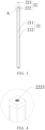
FIG. 3 is a schematic structural diagram of a hold-down strip provided by some embodiments of the disclosure. -
FIG. 4 is an enlarged diagram at position A inFIG. 3 . -
FIG. 5 is a schematic structural diagram of an end plate provided by some embodiments of the disclosure. -
FIG. 6 is a schematic structural diagram of a battery pack provided by some embodiments of the disclosure. - 10, battery module; 1, end plate; 11, protrusion; 2, hold-down strip; 21, hold-down strip body; 211, first hold-down strip portion; 212, second hold-down strip portion; 22, connecting component; 221, preload member; 222, connecting portion; 2221, connecting hole; 3, cell; 4, cell group; 6, adhesive layer; 7, foam; and 100, battery pack.
- In the description of the disclosure, unless otherwise specified or limited, the terms "connected", "connection", and "fixed" should be understood broadly. For example, it can be a fixed connection, a detachable connection, or an integrated unit; alternatively, it can be a mechanical connection or an electrical connection; alternatively, it can be a direct connection or an indirect connection through an intermediate medium; and alternatively, it can be an internal connection of two components or an interaction relationship between two components. For an ordinary person skilled in the art, specific meanings of the above terms in the disclosure can be understood based on specific situations.
- In the disclosure, unless otherwise specified or limited, "a first feature above or below a second feature" may include a direct contact between the first feature and the second feature, or an indirect contact through another feature between the first feature and the second feature, instead of the direct contact. Moreover, the first feature is disposed "on" or "above" the second feature, indicating that the first feature is directly above or diagonally above the second feature, or simply indicating that the first feature is horizontally higher than the second feature. The phrase "the first feature is disposed below or under the second feature" indicates that the first feature is directly below or diagonally below the second feature, or simply indicates that the first feature is horizontally lower than the second feature.
- In the description of the disclosure, directional or positional relationships indicated by the terms "on", "above", "below", "left", "right", "front", "back", and the like, are based on the directional or positional relationships shown in the drawings, which are used only for the convenience of describing the disclosure and simplifying the description, rather than indicating or implying that the devices or elements must have a specific direction, be constructed or operated in a specific direction. Therefore, the terms cannot be interpreted as a limitation on the disclosure. In addition, the terms "first" and "second" are used only for the purpose of description and do not have specific meanings.
- As illustrated in
FIG. 1 and FIG. 2 , some embodiments of the disclosure provide abattery module 10, which includes twoend plates 1, at least one hold-down strip 2, and a plurality ofcells 3. The plurality ofcells 3 are arranged sequentially in a first direction X to form a cell group 4. The twoend plates 1 abut against two ends of the cell group 4, respectively. - In some embodiments, a shape of each of the two
end plates 1 can match a shape of each of thecells 3. For example, when thecells 3 are square cells, each of the twoend plates 1 is square. Furthermore, a size of each of the twoend plates 1 can also match a size of each of thecells 3. By disposing the size of each of the twoend plates 1 matching the size of each of thecells 3, the constraint effect of the twoend plates 1 on thecells 3 can be improved. - In some embodiments, the hold-
down strip 2 abuts against the cell group 4. The hold-down strip 2 includes a hold-down strip body 21 and at least one connectingcomponent 22, the hold-downstrip body 21 extends in the first direction X, the connectingcomponent 22 is connected to an end of the hold-downstrip body 21 in the first direction X, and the connectingcomponent 22 movably abuts against a side of one of the twoend plates 1 away from the cell group 4. - The hold-
down strip 2 may include one connectingcomponent 22 or two connectingcomponents 22. In some embodiments, the hold-down strip 2 includes one connectingcomponent 22, an end of the hold-downstrip body 21 in the first direction X is connected to a side of the one connectingcomponent 22, and another end of the hold-downstrip body 21 in the first direction X is fixedly connected to one of the twoend plates 1; and another side of the one connectingcomponent 22 is movably abuts against another of the twoend plates 1. In some embodiments, the hold-down strip 2 includes two connectingcomponents 22, the two connectingcomponents 22 are connected to two opposite ends of the hold-downstrip body 21 in the first direction X, respectively; and the two connectingcomponents 22 movably abut against the twoend plates 1, respectively. - In some embodiments, as illustrated in
FIG. 1 and FIG. 2 , the plurality ofcells 3 are square cells, and the plurality ofcells 3 are arranged sequentially in a thickness direction of the cells 3 (the first direction X) to form the cell group 4. The twoend plates 1 abut against two ends of the cell group 4, respectively. - In some embodiments, as illustrated in
FIG. 3 , the hold-down strip 2 includes the hold-down strip body 21 and two connectingcomponents 22. The hold-down strip body 21 extends in the first direction X, and the two connectingcomponents 22 are connected to two ends of the hold-downstrip body 21 in the first direction X. In some embodiments, the two connectingcomponents 22 and the hold-down strip body 21 are integrally formed, and the two connectingcomponents 22 are connected to two ends of the hold-downstrip body 21, respectively. - The hold-down
strip 2 abuts against the cell group 4, and each of the two connectingcomponents 22 movably abuts against a side of one of the twoend plates 1 away from the cell group 4. By disposing the hold-down strip 2 abutting against the cell group 4, and disposing the hold-downstrip 2 movably abutting against the twoend plates 1 through the two connectingcomponents 22, the twoend plates 1 and the hold-down strip 2 can form a cell frame for constraining the cell group 4, providing a constraint effect on the cell group 4 in various directions. Moreover, the two connectingcomponents 22 located at two ends of the hold-downstrip body 2 movably abut against the twoend plates 1, respectively, so that the twoend plates 1 are close to each other to clamp the cell group 4, which improves the binding force on the cell group 4 in the first direction X, further enhances the constraint effect of the hold-downstrip 2 and the twoend plates 1 on the cell group 4 in the first direction X, improves the anti-expansion performance of thebattery module 10 in various directions, and ensures the structural stability and reliability of thebattery module 10 in its entire life cycle. - It can be understood that a preload force is one of the important indicators in the design of the battery module, which has a great influence on the cycle life and initial stiffness of the battery module. However, in related art, the battery module usually adopts the design method of a fixed preload force, which cannot adjust an initial preload force of the battery module to match fluctuation of sizes of incoming materials.
- In some embodiments, as illustrated in
FIG. 3 , each of the two connectingcomponents 22 includes apreload member 221 and a connectingportion 222. The connectingportion 222 is connected to an end of the hold-downstrip body 21. Thepreload member 221 is movably connected to the connectingportion 222 in the first direction X, and an end of thepreload member 221 away from the connectingportion 222 abuts against one of the twoend plates 1. - In the above embodiments, the hold-
down strip body 21 is connected to the connectingportion 222 through thepreload member 221 in the first direction X, and an end of thepreload member 221 away from the connectingportion 222 abuts against the twoend plates 1, so as to achieve the connection between the hold-down strip 2 and the twoend plates 1. Moreover, the flexible adjustment of the preload force of thebattery module 10 can be achieved by disposing thepreload member 221, thereby solving the problem of an excessive or insufficient preload force that is prone to occur when there is fluctuation in sizes of incoming materials, and avoiding affecting the cycle life of thebattery module 10 due to excessive or insufficient preload. - In some embodiments, as illustrated in
FIG. 5 , aprotrusion 11 extending in the first direction X is provided on each of the twoend plates 1, and an end of theprotrusion 11 away from the twoend plates 1 is inserted into the connectingportion 222. - In the above embodiments, the
protrusion 11 is disposed on each of the twoend plates 1, and an end of theprotrusion 11 away from the twoend plates 1 is inserted into the connectingportion 222, so that theprotrusion 11 can provide a positioning effect for the twoend plates 1 and the hold-down strip 2, thereby better achieving the connection between the twoend plates 1 and the hold-down strip 2. - In some embodiments, the
protrusion 11 can be in a cylindrical shape, a cubic column shape, or the like. - Furthermore, as illustrated in
FIG. 3 and FIG. 4 , the connectingportion 222 is provided with a connectinghole 2221, theprotrusion 11 is inserted into a part of the connectinghole 2221, and thepreload member 221 penetrates through another part of the connectinghole 2221 and abuts against theprotrusion 11. - On the one hand, the
protrusion 11 is inserted into the connectinghole 2221 to play a positioning effect. On the other hand, thepreload member 221 abuts against theprotrusion 11 in the connectinghole 2221, achieving the connection between the twoend plates 1 and the hold-down strip 2, and making the structure more compact. - When the cell group 4 expands, it will generate outward expansion pressure on the hold-
down strip 2 distributed around the cell group 4, increasing the radial force on thepreload member 221, and affecting the adjustment of the preload force and disassembly of thepreload member 221. In the embodiments, theprotrusion 11 disposed on the twoend plates 1 can play a positioning effect and improve the radial limiting effect, when the cell group 4 expands and deforms, the radial force on thepreload member 221 during the non-uniform deformation of thebattery module 10 can be reduced, thereby minimizing the influence on thebattery module 10 caused by the expansion of the cell group 4. - In some embodiments, the
preload member 221 is in threaded connection with the connectinghole 2221. - By disposing the
preload member 221 being in threaded connection with the connectinghole 2221, thepreload member 221 can be connected to the connectingportion 222 to abut against the twoend plates 1, achieving the connection between the hold-down strip 2 and the twoend plates 1. Moreover, the connectinghole 2221 matches with theprotrusion 11 to achieve the positioning effect, and thepreload member 221 is in threaded connection with the connectinghole 2221 to facilitate the flexible adjustment of the preload force. - For example, the
preload member 221 can be a fastening adjustment bolt, and the connectinghole 2221 can be a threaded hole. - In some embodiments, as illustrated in
FIG. 3 , the hold-down strip body 21 includes a first hold-down strip portion 211 and a second hold-down strip portion 212 independently extending in the first direction X, and the second hold-down strip portion 212 is connected to a side of the first hold-down strip portion 211. The first hold-down strip portion 211 and the second hold-down strip portion 212 abut against adjacent two sides of the cell group 4, respectively. Adjacent two sides of each of the connectingcomponents 22 are connected to the first hold-down strip portion 211 and the second hold-down strip portion 212, respectively. - The first hold-
down strip portion 211 and the second hold-down strip portion 212 press against adjacent two sides of the cell group 4, respectively, so that the first hold-down strip portion 211 and the second hold-down strip portion 212 can provide constraint effects on the cell group 4 in different directions. Moreover, the structural strength of the cell group 4 in two directions can be improved. - In some embodiments, each of the connecting
components 22 includes the connectingportion 222, two sides of the connectingportion 222 are connected to the first hold-down strip portion 211 and the second hold-down strip portion 212, respectively, and any two of the connectingportion 222, the first hold-down strip portion 211, and the second hold-down strip portion 212 are perpendicular to each other. - For example, as illustrated in
FIG. 3 , the first hold-down strip portion 211 and the second hold-down strip portion 212 are perpendicular to each other, that is, the hold-down strip body 21 is a L-shaped structure, and the connectingportion 222 is perpendicular to the first hold-down strip portion 211 and the second hold-down strip portion 212. For the cell group 4 composed of square cells, the first hold-down strip portion 211 and the second hold-down strip portion 212 that are perpendicular to each other can improve the structural strength of the cell group 4 in two directions. Moreover, the first hold-down strip portion 211, the second hold-down strip portion 212, and the connectingportion 222 that are perpendicular to each other can play a positioning effect and a limiting effect on each of the twoend plates 1 in three directions, which can improve the structural stability of thebattery module 10. - In the disclosure, a width of the first hold-
down strip portion 211 and a width of the second hold-down strip portion 212 may be the same or different. In practical applications, the widths and relative positions of the first hold-down strip portion 211 and the second hold-down strip portion 212 can be adjusted according to different constraint effects that needs to be provided in different directions. - In some embodiments, the
battery module 10 includes at least two hold-down strips 2. For example, the number of the hold-downstrips 2 is two, and the two hold-downstrips 2 are disposed at two oblique diagonal corners of the cell group 4, respectively. - In the embodiments, each of the two hold-down
strips 2 includes the first hold-down strip portion 211 and the second hold-down strip portion 212, which can provide the constraint effect on the cell group 4 in two different directions. Furthermore, the two hold-downstrips 2 disposed at two oblique diagonal corners of the cell group 4 can provide good clamping and fixing effects on the cell group 4, so that the hold-downstrips 2 and the twoend plates 1 can cooperate to provide constraint effects on the cell group 4 in various directions. - It can be understood that the structural stability of the
battery module 10 can be further improved by increasing the number of the hold-downstrips 2, so as to provide a better constraint effect on the cell group 4. In some embodiments, the number of the hold-downstrips 2 are four. For example, as illustrated inFIG. 1 and FIG. 2 , four hold-downstrips 2 are disposed at four corners of the cell group 4 composed of square cells, respectively. The mutual cooperation of the four hold-downstrips 2 makes the cell group 4 more stable, which can significantly improve the overall stiffness of thebattery module 10. - In some embodiments, as illustrated in
FIG. 2 , thebattery module 10 further includes anadhesive layer 6, and theadhesive layer 6 is disposed between at least one of the hold-downstrips 2 and the cell group 4. - At least one of the hold-down
strips 2 and the cell group 4 are bonded together through theadhesive layer 6 to form a sandwich structure, so that the hold-downstrips 2 and the cell group 4 form a whole. For example, as illustrated inFIG. 2 , theadhesive layer 6 is disposed between each of the hold-downstrips 2 in a L-shape and the cell group 4 composed of square cells. Theadhesive layer 6 bonds the hold-downstrips 2 and the cell group 4 together, and also makes the plurality ofcells 3 in the cell group 4 form a whole, so that the hold-downstrips 2 not only play a structural stability role on thebattery module 10 in a height direction and a width direction, but also improve the structural stability of thebattery module 10 in a length direction. - In some embodiments, as illustrated in
FIG. 2 , thebattery module 10 further includes afoam 7, thefoam 7 is disposed between every adjacent two of thecells 3, and between each of the twoend plates 1 and one of thecells 3 adjacent to each of the twoend plates 1. Therefore, thefoam 7 can provide gap between every adjacent two of thecells 3, and between each of the twoend plates 1 and one of thecells 3 adjacent to each of the twoend plates 1, and thefoam 7 can also improve cushioning effects between every adjacent two of thecells 3, and between each of the twoend plates 1 and one of thecells 3 adjacent to each of the twoend plates 1. - Alternatively, the
foam 7 is disposed between every adjacent two of thecells 3. Therefore, thefoam 7 can provide the gap between every adjacent two of thecells 3, and improve a cushioning effect between every adjacent two of thecells 3. - Alternatively, the
foam 7 is disposed between each of the twoend plates 1 and one of thecells 3 adjacent to each of the twoend plates 1. Therefore, thefoam 7 can provide the gap between each of the twoend plates 1 and one of thecells 3 adjacent to each of the twoend plates 1, and improve a cushioning effect between each of the twoend plates 1 and one of thecells 3 adjacent to each of the twoend plates 1. - Furthermore, the
foam 7 may be a hollow structure. Alternatively, thefoam 7 covers a periphery of an edge of each of thecells 3, and a gap is formed between every adjacent two of thecells 3. Alternatively, thefoam 7 covers a periphery of an edge of a side of each of the twoend plates 1 close to thecells 3, and a gap is formed between each of the twoend plates 1 and one of thecells 3 adjacent to each of the twoend plates 1. Alternatively, thefoam 7 covers both of a periphery of an edge of each of thecells 3 and a periphery of an edge of a side of each of the twoend plates 1 close to thecells 3, and a gap is formed between every adjacent two of thecells 3, and between each of the twoend plates 1 and one of thecells 3 adjacent to each of the twoend plates 1. - By setting the
foam 7 being a hollow structure, on the one hand, because an area of the hollow structure is small, the adjusting pressure when adjusting the preload force can be reduced; moreover, because thefoam 7 covers a periphery of an edge of each of thecells 3 and/or a periphery of an edge of each of the twoend plates 1, the resistance generated in the fastening adjustment process is small. On the other hand, a cavity can be formed between each of the twoend plates 1 and one of thecells 3 adjacent to each of the twoend plates 1, and/or between every adjacent two of thecells 3, so that the overall heat dissipation capacity of thebattery module 10 can be improved, and an expansion space can be formed between every adjacent two of thecells 3. - For example, as illustrated in
FIG. 2 , thecells 3 are square cells, and thefoam 7 is a square frame structure corresponding to thecells 3, and thefoam 7 with the square frame structure is disposed between every adjacent two of thecells 3, and between each of the twoend plates 1 and one of thecells 3 adjacent to each of the twoend plates 1. - As illustrated in
FIG. 6 , some embodiments of the disclosure provide abattery pack 100 including thebattery module 10 as described above. - It should be noted that the
battery pack 100 may include only onebattery module 10 or a plurality ofbattery modules 10. - Because the
battery pack 100 has excellent anti-expansion performance in various directions, and has better structural stability and reliability in the entire life cycle, the safety and reliability of thebattery pack 100 using thebattery module 10 can be improved.
Claims (14)
- A battery module (10), characterized in that the battery module (10) comprises:a plurality of cells (3) arranged sequentially in a first direction to form a cell group (4);two end plates (1) abutting against two ends of the cell group (4), respectively; andat least one hold-down strip (2) abutting against the cell group (4), wherein the hold-down strip (2) comprises a hold-down strip body (21) and a connecting component (22), the hold-down strip body (21) extends in the first direction, the connecting component (22) is connected to an end of the hold-down strip body (21) in the first direction, and the connecting component (22) movably abuts against a side of one of the two end plates (1) away from the cell group (4).
- The battery module (10) of claim 1, wherein the connecting component (22) comprises a connecting portion (222) and a preload member (221), and the preload member (221) is movably connected to the connecting portion (222) in the first direction; and
the connecting portion (222) is connected to an end of the hold-down strip body (21), and an end of the preload member (221) away from the connecting portion (222) abuts against one of the two end plates (1). - The battery module (10) of claim 2, wherein a protrusion (11) extending in the first direction is provided on at least one of the two end plates (1), and an end of the protrusion (11) away from the two end plates (1) is inserted into the connecting portion (222).
- The battery module (10) of claim 3, wherein the protrusion (11) is in a cylindrical shape or a cubic column shape.
- The battery module (10) of claim 3 or 4, wherein the connecting portion (222) is provided with a connecting hole (2221), the protrusion (11) is inserted into a part of the connecting hole (2221), and the preload member (221) penetrates through another part of the connecting hole (2221) and abuts against the protrusion (11).
- The battery module (10) of claim 5, wherein the preload member (221) is in threaded connection with the connecting hole (2221).
- The battery module (10) of any one of claims 1 to 6, wherein the hold-down strip body (21) comprises a first hold-down strip portion (211) and a second hold-down strip portion (212) independently extending in the first direction, and the second hold-down strip portion (212) is connected to a side of the first hold-down strip portion (211); and
wherein the first hold-down strip portion (211) and the second hold-down strip portion (212) abut against adjacent two sides of the cell group (4), respectively, and adjacent two sides of the connecting component (22) are connected to the first hold-down strip portion (211) and the second hold-down strip portion (212), respectively. - The battery module (10) of claim 7, wherein the connecting component (22) comprises a connecting portion (222), two sides of the connecting portion (222) are connected to the first hold-down strip portion (211) and the second hold-down strip portion (212), respectively, and any two of the connecting portion (222), the first hold-down strip portion (211), and the second hold-down strip portion (212) are perpendicular to each other.
- The battery module (10) of claim 7 or 8, wherein the battery module (10) comprises two hold-down strips (2) disposed at two oblique diagonal corners of the cell group (4), respectively.
- The battery module (10) of any one of claims 1 to 9, further comprising an adhesive layer (6) disposed between the hold-down strip (2) and the cell group (4).
- The battery module (10) of any one of claims 1 to 10, wherein the plurality of cells (3) are square cells (3), and the plurality of cells (3) are arranged sequentially in a thickness direction of the cells (3).
- The battery module (10) of any one of claims 1 to 10, further comprising a foam (7);wherein the foam (7) is disposed between every adjacent two of the plurality of cells (3);optionally, the foam (7) is disposed between each of the two end plates (1) and one of the plurality of cells (3) adjacent to each of the two end plates (1);optionally, the foam (7) is disposed between every adjacent two of the plurality of cells (3), and between each of the two end plates (1) and one of the plurality of cells (3) adjacent to each of the two end plates (1).
- The battery module (10) of claim 12, wherein the foam (7) is a hollow structure;wherein the foam (7) covers a periphery of an edge of each of the plurality of cells (3), and a gap is formed between every adjacent two of the plurality of cells (3);optionally, the foam (7) covers a periphery of an edge of a side of each of the two end plates (1) close to the plurality of cells (3), and a gap is formed between each of the two end plates (1) and one of the plurality of cells (3) adjacent to each of the two end plates (1);optionally, the foam (7) covers both of a periphery of an edge of each of the plurality of cells (3) and a periphery of an edge of a side of each of the two end plates (1) close to the plurality of cells (3), and a gap is formed between every adjacent two of the plurality of cells (3), and between each of the two end plates (1) and one of the plurality of cells (3) adjacent to each of the two end plates (1).
- A battery pack (100), characterized in that battery pack (100) comprises the battery module (10) as claimed in any one of claims 1 to 13.
Applications Claiming Priority (2)
| Application Number | Priority Date | Filing Date | Title |
|---|---|---|---|
| CN202323529198.6U CN222530707U (en) | 2023-12-22 | 2023-12-22 | Battery module and battery pack |
| PCT/CN2024/115852 WO2025130137A1 (en) | 2023-12-22 | 2024-08-30 | Battery module and battery pack |
Publications (1)
| Publication Number | Publication Date |
|---|---|
| EP4576296A1 true EP4576296A1 (en) | 2025-06-25 |
Family
ID=94083650
Family Applications (1)
| Application Number | Title | Priority Date | Filing Date |
|---|---|---|---|
| EP24222723.9A Pending EP4576296A1 (en) | 2023-12-22 | 2024-12-23 | Battery module and battery pack |
Country Status (4)
| Country | Link |
|---|---|
| US (1) | US20250210788A1 (en) |
| EP (1) | EP4576296A1 (en) |
| JP (1) | JP2025100481A (en) |
| KR (1) | KR20250098900A (en) |
Citations (4)
| Publication number | Priority date | Publication date | Assignee | Title |
|---|---|---|---|---|
| US20110236739A1 (en) * | 2010-03-24 | 2011-09-29 | Denso Corporation | Battery pack |
| US20170358788A1 (en) * | 2015-02-16 | 2017-12-14 | Kabushiki Kaisha Toyota Jidoshokki | Battery module and method for manufacturing battery module |
| JP2019016503A (en) * | 2017-07-06 | 2019-01-31 | 本田技研工業株式会社 | Battery module |
| WO2021001613A1 (en) * | 2019-07-02 | 2021-01-07 | Psa Automobiles Sa | Storage module with multiple cells preloaded by springs |
Family Cites Families (7)
| Publication number | Priority date | Publication date | Assignee | Title |
|---|---|---|---|---|
| WO2014024431A1 (en) * | 2012-08-09 | 2014-02-13 | 三洋電機株式会社 | Battery system, vehicle provided with battery system, and electricity storage device |
| CN109037527B (en) * | 2018-07-25 | 2024-03-19 | 江苏正力新能电池技术有限公司 | Battery module |
| JP7074085B2 (en) * | 2019-01-23 | 2022-05-24 | トヨタ自動車株式会社 | Battery device |
| JP7366636B2 (en) * | 2019-08-07 | 2023-10-23 | 三洋電機株式会社 | Power supply device, electric vehicle equipped with this power supply device, and power storage device |
| JP7286599B2 (en) * | 2020-09-29 | 2023-06-05 | プライムプラネットエナジー&ソリューションズ株式会社 | Storage module and manufacturing method thereof |
| CN218548616U (en) * | 2022-11-11 | 2023-02-28 | 蜂巢能源科技股份有限公司 | Module curb plate, battery module and battery package |
| CN219067118U (en) * | 2022-12-23 | 2023-05-23 | 上海兰钧新能源科技有限公司 | Fixing structure of battery cell module and battery cell module |
-
2024
- 2024-10-25 KR KR1020240147174A patent/KR20250098900A/en active Pending
- 2024-12-19 JP JP2024224380A patent/JP2025100481A/en active Pending
- 2024-12-20 US US18/991,277 patent/US20250210788A1/en active Pending
- 2024-12-23 EP EP24222723.9A patent/EP4576296A1/en active Pending
Patent Citations (4)
| Publication number | Priority date | Publication date | Assignee | Title |
|---|---|---|---|---|
| US20110236739A1 (en) * | 2010-03-24 | 2011-09-29 | Denso Corporation | Battery pack |
| US20170358788A1 (en) * | 2015-02-16 | 2017-12-14 | Kabushiki Kaisha Toyota Jidoshokki | Battery module and method for manufacturing battery module |
| JP2019016503A (en) * | 2017-07-06 | 2019-01-31 | 本田技研工業株式会社 | Battery module |
| WO2021001613A1 (en) * | 2019-07-02 | 2021-01-07 | Psa Automobiles Sa | Storage module with multiple cells preloaded by springs |
Also Published As
| Publication number | Publication date |
|---|---|
| JP2025100481A (en) | 2025-07-03 |
| US20250210788A1 (en) | 2025-06-26 |
| KR20250098900A (en) | 2025-07-01 |
Similar Documents
| Publication | Publication Date | Title |
|---|---|---|
| JP6091921B2 (en) | Battery module and battery pack | |
| US11264669B2 (en) | Battery box and battery module | |
| CN213150897U (en) | Power battery package structure | |
| JP6184959B2 (en) | Battery system, vehicle including battery system, and power storage device | |
| WO2019128640A1 (en) | Composite end plate and battery module | |
| JP2005285625A (en) | Battery frame and battery pack | |
| EP3886205B1 (en) | Battery module | |
| CN217485614U (en) | Buffer device and battery module | |
| US20250023168A1 (en) | Battery and electric-consuming device | |
| CN221687711U (en) | Batteries and electrical devices | |
| KR20240151803A (en) | Batteries and electrical devices | |
| EP4576296A1 (en) | Battery module and battery pack | |
| CN210092284U (en) | A large module structure of lithium ion battery | |
| KR102936064B1 (en) | Power storage device | |
| CN215731960U (en) | Battery module and battery pack thereof | |
| CN222463330U (en) | Electric connecting piece, battery pack and electric equipment | |
| CN220439792U (en) | Cell modules, battery packs and vehicles | |
| CN219696501U (en) | Five-sided compact CTP battery pack external stacking tool | |
| CN222530707U (en) | Battery module and battery pack | |
| CN212209588U (en) | The battery module of the battery pack and the battery pack | |
| CN210897429U (en) | Power battery pack | |
| CN120709448B (en) | Clamp, isostatic pressing device and battery production equipment | |
| KR20210121466A (en) | Battery Module and Assembly Method Thereof | |
| CN222190933U (en) | A thermal insulation component, battery module and battery pack | |
| CN224036555U (en) | A battery module and battery pack |
Legal Events
| Date | Code | Title | Description |
|---|---|---|---|
| PUAI | Public reference made under article 153(3) epc to a published international application that has entered the european phase |
Free format text: ORIGINAL CODE: 0009012 |
|
| STAA | Information on the status of an ep patent application or granted ep patent |
Free format text: STATUS: REQUEST FOR EXAMINATION WAS MADE |
|
| 17P | Request for examination filed |
Effective date: 20241223 |
|
| AK | Designated contracting states |
Kind code of ref document: A1 Designated state(s): AL AT BE BG CH CY CZ DE DK EE ES FI FR GB GR HR HU IE IS IT LI LT LU LV MC ME MK MT NL NO PL PT RO RS SE SI SK SM TR |