EP4576295A1 - Battery cell - Google Patents
Battery cell Download PDFInfo
- Publication number
- EP4576295A1 EP4576295A1 EP24221944.2A EP24221944A EP4576295A1 EP 4576295 A1 EP4576295 A1 EP 4576295A1 EP 24221944 A EP24221944 A EP 24221944A EP 4576295 A1 EP4576295 A1 EP 4576295A1
- Authority
- EP
- European Patent Office
- Prior art keywords
- plate
- battery cell
- electrode
- cap plate
- flag
- Prior art date
- Legal status (The legal status is an assumption and is not a legal conclusion. Google has not performed a legal analysis and makes no representation as to the accuracy of the status listed.)
- Pending
Links
Images




Classifications
-
- H—ELECTRICITY
- H01—ELECTRIC ELEMENTS
- H01M—PROCESSES OR MEANS, e.g. BATTERIES, FOR THE DIRECT CONVERSION OF CHEMICAL ENERGY INTO ELECTRICAL ENERGY
- H01M50/00—Constructional details or processes of manufacture of the non-active parts of electrochemical cells other than fuel cells, e.g. hybrid cells
- H01M50/50—Current conducting connections for cells or batteries
- H01M50/531—Electrode connections inside a battery casing
- H01M50/533—Electrode connections inside a battery casing characterised by the shape of the leads or tabs
-
- H—ELECTRICITY
- H01—ELECTRIC ELEMENTS
- H01M—PROCESSES OR MEANS, e.g. BATTERIES, FOR THE DIRECT CONVERSION OF CHEMICAL ENERGY INTO ELECTRICAL ENERGY
- H01M50/00—Constructional details or processes of manufacture of the non-active parts of electrochemical cells other than fuel cells, e.g. hybrid cells
- H01M50/10—Primary casings; Jackets or wrappings
- H01M50/102—Primary casings; Jackets or wrappings characterised by their shape or physical structure
- H01M50/107—Primary casings; Jackets or wrappings characterised by their shape or physical structure having curved cross-section, e.g. round or elliptic
-
- H—ELECTRICITY
- H01—ELECTRIC ELEMENTS
- H01M—PROCESSES OR MEANS, e.g. BATTERIES, FOR THE DIRECT CONVERSION OF CHEMICAL ENERGY INTO ELECTRICAL ENERGY
- H01M10/00—Secondary cells; Manufacture thereof
- H01M10/04—Construction or manufacture in general
- H01M10/0422—Cells or battery with cylindrical casing
-
- H—ELECTRICITY
- H01—ELECTRIC ELEMENTS
- H01M—PROCESSES OR MEANS, e.g. BATTERIES, FOR THE DIRECT CONVERSION OF CHEMICAL ENERGY INTO ELECTRICAL ENERGY
- H01M10/00—Secondary cells; Manufacture thereof
- H01M10/04—Construction or manufacture in general
- H01M10/0431—Cells with wound or folded electrodes
-
- H—ELECTRICITY
- H01—ELECTRIC ELEMENTS
- H01M—PROCESSES OR MEANS, e.g. BATTERIES, FOR THE DIRECT CONVERSION OF CHEMICAL ENERGY INTO ELECTRICAL ENERGY
- H01M50/00—Constructional details or processes of manufacture of the non-active parts of electrochemical cells other than fuel cells, e.g. hybrid cells
- H01M50/10—Primary casings; Jackets or wrappings
- H01M50/14—Primary casings; Jackets or wrappings for protecting against damage caused by external factors
-
- H—ELECTRICITY
- H01—ELECTRIC ELEMENTS
- H01M—PROCESSES OR MEANS, e.g. BATTERIES, FOR THE DIRECT CONVERSION OF CHEMICAL ENERGY INTO ELECTRICAL ENERGY
- H01M50/00—Constructional details or processes of manufacture of the non-active parts of electrochemical cells other than fuel cells, e.g. hybrid cells
- H01M50/10—Primary casings; Jackets or wrappings
- H01M50/147—Lids or covers
- H01M50/148—Lids or covers characterised by their shape
- H01M50/152—Lids or covers characterised by their shape for cells having curved cross-section, e.g. round or elliptic
-
- H—ELECTRICITY
- H01—ELECTRIC ELEMENTS
- H01M—PROCESSES OR MEANS, e.g. BATTERIES, FOR THE DIRECT CONVERSION OF CHEMICAL ENERGY INTO ELECTRICAL ENERGY
- H01M50/00—Constructional details or processes of manufacture of the non-active parts of electrochemical cells other than fuel cells, e.g. hybrid cells
- H01M50/10—Primary casings; Jackets or wrappings
- H01M50/172—Arrangements of electric connectors penetrating the casing
- H01M50/174—Arrangements of electric connectors penetrating the casing adapted for the shape of the cells
- H01M50/179—Arrangements of electric connectors penetrating the casing adapted for the shape of the cells for cells having curved cross-section, e.g. round or elliptic
-
- H—ELECTRICITY
- H01—ELECTRIC ELEMENTS
- H01M—PROCESSES OR MEANS, e.g. BATTERIES, FOR THE DIRECT CONVERSION OF CHEMICAL ENERGY INTO ELECTRICAL ENERGY
- H01M50/00—Constructional details or processes of manufacture of the non-active parts of electrochemical cells other than fuel cells, e.g. hybrid cells
- H01M50/10—Primary casings; Jackets or wrappings
- H01M50/183—Sealing members
- H01M50/186—Sealing members characterised by the disposition of the sealing members
- H01M50/188—Sealing members characterised by the disposition of the sealing members the sealing members being arranged between the lid and terminal
-
- H—ELECTRICITY
- H01—ELECTRIC ELEMENTS
- H01M—PROCESSES OR MEANS, e.g. BATTERIES, FOR THE DIRECT CONVERSION OF CHEMICAL ENERGY INTO ELECTRICAL ENERGY
- H01M50/00—Constructional details or processes of manufacture of the non-active parts of electrochemical cells other than fuel cells, e.g. hybrid cells
- H01M50/20—Mountings; Secondary casings or frames; Racks, modules or packs; Suspension devices; Shock absorbers; Transport or carrying devices; Holders
- H01M50/233—Mountings; Secondary casings or frames; Racks, modules or packs; Suspension devices; Shock absorbers; Transport or carrying devices; Holders characterised by physical properties of casings or racks, e.g. dimensions
- H01M50/24—Mountings; Secondary casings or frames; Racks, modules or packs; Suspension devices; Shock absorbers; Transport or carrying devices; Holders characterised by physical properties of casings or racks, e.g. dimensions adapted for protecting batteries from their environment, e.g. from corrosion
-
- H—ELECTRICITY
- H01—ELECTRIC ELEMENTS
- H01M—PROCESSES OR MEANS, e.g. BATTERIES, FOR THE DIRECT CONVERSION OF CHEMICAL ENERGY INTO ELECTRICAL ENERGY
- H01M50/00—Constructional details or processes of manufacture of the non-active parts of electrochemical cells other than fuel cells, e.g. hybrid cells
- H01M50/20—Mountings; Secondary casings or frames; Racks, modules or packs; Suspension devices; Shock absorbers; Transport or carrying devices; Holders
- H01M50/249—Mountings; Secondary casings or frames; Racks, modules or packs; Suspension devices; Shock absorbers; Transport or carrying devices; Holders specially adapted for aircraft or vehicles, e.g. cars or trains
-
- H—ELECTRICITY
- H01—ELECTRIC ELEMENTS
- H01M—PROCESSES OR MEANS, e.g. BATTERIES, FOR THE DIRECT CONVERSION OF CHEMICAL ENERGY INTO ELECTRICAL ENERGY
- H01M50/00—Constructional details or processes of manufacture of the non-active parts of electrochemical cells other than fuel cells, e.g. hybrid cells
- H01M50/50—Current conducting connections for cells or batteries
- H01M50/528—Fixed electrical connections, i.e. not intended for disconnection
-
- H—ELECTRICITY
- H01—ELECTRIC ELEMENTS
- H01M—PROCESSES OR MEANS, e.g. BATTERIES, FOR THE DIRECT CONVERSION OF CHEMICAL ENERGY INTO ELECTRICAL ENERGY
- H01M50/00—Constructional details or processes of manufacture of the non-active parts of electrochemical cells other than fuel cells, e.g. hybrid cells
- H01M50/50—Current conducting connections for cells or batteries
- H01M50/531—Electrode connections inside a battery casing
-
- H—ELECTRICITY
- H01—ELECTRIC ELEMENTS
- H01M—PROCESSES OR MEANS, e.g. BATTERIES, FOR THE DIRECT CONVERSION OF CHEMICAL ENERGY INTO ELECTRICAL ENERGY
- H01M50/00—Constructional details or processes of manufacture of the non-active parts of electrochemical cells other than fuel cells, e.g. hybrid cells
- H01M50/50—Current conducting connections for cells or batteries
- H01M50/531—Electrode connections inside a battery casing
- H01M50/538—Connection of several leads or tabs of wound or folded electrode stacks
-
- H—ELECTRICITY
- H01—ELECTRIC ELEMENTS
- H01M—PROCESSES OR MEANS, e.g. BATTERIES, FOR THE DIRECT CONVERSION OF CHEMICAL ENERGY INTO ELECTRICAL ENERGY
- H01M50/00—Constructional details or processes of manufacture of the non-active parts of electrochemical cells other than fuel cells, e.g. hybrid cells
- H01M50/50—Current conducting connections for cells or batteries
- H01M50/543—Terminals
- H01M50/545—Terminals formed by the casing of the cells
-
- H—ELECTRICITY
- H01—ELECTRIC ELEMENTS
- H01M—PROCESSES OR MEANS, e.g. BATTERIES, FOR THE DIRECT CONVERSION OF CHEMICAL ENERGY INTO ELECTRICAL ENERGY
- H01M50/00—Constructional details or processes of manufacture of the non-active parts of electrochemical cells other than fuel cells, e.g. hybrid cells
- H01M50/10—Primary casings; Jackets or wrappings
- H01M50/147—Lids or covers
- H01M50/148—Lids or covers characterised by their shape
- H01M50/15—Lids or covers characterised by their shape for prismatic or rectangular cells
-
- Y—GENERAL TAGGING OF NEW TECHNOLOGICAL DEVELOPMENTS; GENERAL TAGGING OF CROSS-SECTIONAL TECHNOLOGIES SPANNING OVER SEVERAL SECTIONS OF THE IPC; TECHNICAL SUBJECTS COVERED BY FORMER USPC CROSS-REFERENCE ART COLLECTIONS [XRACs] AND DIGESTS
- Y02—TECHNOLOGIES OR APPLICATIONS FOR MITIGATION OR ADAPTATION AGAINST CLIMATE CHANGE
- Y02E—REDUCTION OF GREENHOUSE GAS [GHG] EMISSIONS, RELATED TO ENERGY GENERATION, TRANSMISSION OR DISTRIBUTION
- Y02E60/00—Enabling technologies; Technologies with a potential or indirect contribution to GHG emissions mitigation
- Y02E60/10—Energy storage using batteries
Definitions
- the present disclosure relates to a secondary battery, and more specifically, to a battery cell.
- An embodiment of the present disclosure is to provide a battery cell with improved stability.
- Secondary batteries may be reused multiple times by charging and discharging.
- the secondary batteries are widely used in various industries due to their economical and environmentally friendly characteristics.
- the secondary batteries may be classified into battery cells, battery modules, battery packs, and the like, depending on the unit.
- the battery module, the battery pack, and the like may include multiple battery cells.
- a method for adjusting the direction of heat movement is required. That is, the present inventors have found that the above problems may be solved by disposing the non-polar region where current does not flow at the center, the distance over which the heat moves may be shortened, the dissipation of the heat may be effectively controlled and the stability of a battery cell may be improved.
- the present disclosure may be widely applied in green technology fields such as solar power generation, wind power generation, etc.
- the present disclosure may be applied to eco-friendly devices such as electric vehicles, hybrid vehicles, etc., to prevent climate change by suppressing air pollution and greenhouse gas emissions.
- a battery cell may include an electrode assembly in which an electrode including a flag and a separator are wound, a can accommodating the electrode assembly, a cap plate sealing the can, and a current collector disposed between the cap plate and the electrode assembly and in contact with the flag, the can, and the cap plate, respectively.
- the cap plate may include a non-polar region and a polar region located outside the non-polar region, and the current collector may be in contact with the polar region of the cap plate.
- the non-polar region may include an insulating material that electrically separates it from the polar region.
- polarity of each of the polar region and the can may be the same as polarity of the flag.
- the current collector may include a first plate in contact with the flag and the can, respectively, a second plate in contact with the cap plate, and a connecting part connecting the first plate and the second plate.
- a distance between the second plate and the electrode assembly may be greater than a distance between the first plate and the electrode assembly.
- At least one hole may be formed in the second plate.
- the second plate may include an inner circumferential part with a hole formed at center, and an outer circumferential part located outside the inner circumferential part.
- the cap plate may include an insulating material inserted into the hole.
- the electrode terminal may be inserted into a penetration hole of the can.
- the battery cell may further include an insulating gasket disposed between the can and the electrode terminal.
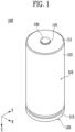
- FIG. 1 is a diagram for explaining a battery cell according to an embodiment.
- the can 110 may accommodate the electrode assembly.
- the can 110 may accommodate the current collector.
- the can 110 may have a shape of a container with a portion open.
- the can 110 may include a material such as various metals such as iron, aluminum, etc., alloys thereof, plastic, ceramic, or carbon.
- the can 110 may include a flat part 111 and a side part 113.
- the flat part 111 may extend from an upper end or a lower end of the side part 113.
- each of the upper end and the lower end may be one of the end parts in a height direction (e.g., a Z-axis direction).
- the flat part 111 may extend from the upper end of the side part 113.
- At least a portion of the flat part 111 may be formed as a flat surface with no height change in a horizontal direction (e.g., an X-axis direction, a Y-axis direction).
- the shape of the XY plane of the flat part 111 may be circular, but is not limited thereto and may be transformed into an oval, triangle, square, polygon, etc.
- the side part 113 may be extended in the height direction (e.g., in the Z-axis direction) from the edge of the flat part 111.
- the flat part 111 and the side part 113 may be formed integrally or formed separately from each other.
- a beading part 115 may be formed in the side part 113.
- the beading part 115 may be a part in which the side part 113 is bent toward an inner space surrounded by the side part 113.
- an opening part with one end open may be formed in the can 110.
- the opening part may be formed on the opposite side of the flat part 111 in the height direction (e.g., in the Z-axis direction). For example, when the flat part 111 is formed at the upper end of the side part 113, the opening part may be formed at the lower end of the side part 113.
- the electrode assembly and the current collector may be inserted into the inner space of the can 110 through the opening part. Thereafter, the beading part 115 may be formed in one region of the side part 113 adj acent to the opening part.
- the cap plate 120 may seal the can 110.
- the cap plate 120 may be coupled to the can 110.
- the can 110 and the cap plate 120 may surround the outer side of the electrode assembly and the current collector.
- the shapes of the cap plate 120 and the can 110 coupled to each other may be cylindrical. However, this is only an example, and the shapes of the cap plate 120 and the can 110 coupled to each other may be modified into various shapes such as a square or a hexahedron.
- the cap plate 120 may be located on the opposite side of the flat part 111. For example, when the flat part 111 is formed at the upper end of the side part 113, the cap plate 120 may be coupled to the lower end of the side part 113.
- the current collector may include at least one of a first current collector and a second current collector.
- the first current collector may be disposed between the cap plate 120 and the electrode assembly.
- the second current collector may be disposed between the flat part 111 of the can 110 and the electrode assembly.
- the current collector may be electrically connected to the electrode of the electrode assembly.
- the current collector may include a conductive material such as copper, gold, silver, aluminum, etc.
- the electrode may include a first electrode and a second electrode.
- the first current collector and the second current collector may be electrically connected to different electrodes of the electrode assembly.
- the first current collector may be connected to the first electrode
- the second current collector may be connected to the second electrode.
- the first current collector may be electrically connected to the can 110 and/or the cap plate 120.
- the second current collector may be electrically connected to the electrode terminal 130.
- the electrode terminal 130 may be located on the opposite side in the height direction (e.g., in the Z-axis direction) from the cap plate 120.
- the electrode terminal 130 may be electrically connected to an external device. In other words, current may flow to the external device through the electrode terminal 130.
- the insulating gasket 135 may be disposed between the can 110 and the electrode terminal 130.
- the insulating gasket 135 may be disposed between the flat part 111 of the can 110 and the electrode terminal 130.
- the insulating gasket 135 may include an insulating material.
- the insulating material may include a material having low electrical conductivity, such as polymer, ceramic, etc.
- FIGS. 2 and 3 are diagrams for explaining an electrode assembly according to an embodiment.
- FIG. 2 is a partially disassembled view of a wound electrode assembly
- FIG. 3 illustrates an electrode assembly in which a flag is formed.
- an electrode assembly 160 may include an electrode 170 and a separator 180.
- the electrode 170 may include a first electrode 171 and a second electrode 175.
- the first electrode 171 and the second electrode 175 may have different polarities.
- the first electrode 171 may be an anode and the second electrode 175 may be a cathode.
- the first electrode 171 may be a cathode and the second electrode 175 may be an anode.
- the electrode 170 may be a plate on which an active material is applied to one region.
- the first electrode 171 may include a first uncoated part 171a on which a first active material is not applied, and a first coated part 171b on which the first active material is applied.
- the second electrode 175 may include a second uncoated part 175a on which a second active material is not applied, and a second coated part 175b on which the second active material is applied.
- the first uncoated part 171a may be formed at an upper end of the first coated part 171b.
- the second uncoated part 175a may be formed at a lower end of the second coated part 175b.
- the first active material may be an anode active material.
- the second active material may be a cathode active material.
- the cathode active material may include at least one of materials such as a lithium transition metal oxide, a nickel-cobalt-manganese lithium oxide, etc.
- the anode active material may include at least one of materials such as a carbon material, lithium, a lithium metal compound, silicon, a silicon compound, tin, a tin compound, etc. Meanwhile, the above-described embodiment is only an embodiment, and the cathode active material and the anode active material may be modified and implemented without limitation in type.
- the electrode 170 may further include an insulating coating part 165 formed at the boundary between the uncoated part and the coated part.
- the insulating coating part 165 may include an insulating material.
- the insulating coating part 165 may improve the mechanical strength of the portion that is bent in the uncoated part to form a flag 170f.
- the separator 180 may include an inner separator 181 disposed between the first electrode 171 and the second electrode 175, and an outer separator 182 disposed on the outside.
- the separator 180 may include an insulating material.
- the separator 180 may block contact between the first electrode 171 and the second electrode 175, and electrically isolate the first electrode 171 and the second electrode 175.
- the electrode assembly 160 may be wound.
- the electrode 170 and the separator 180 may be wound along the central axis (C) in a laminated state.
- the central axis (C) may be in the height direction (e.g., the Z-axis direction).
- the outer separator 182, the first electrode 171, the inner separator 181, and the second electrode 175 may be wound along the central axis (C) in a laminated state.
- the electrode 170 may include a flag 170f.
- the flag 170f may be defined as a region from a bent portion to an end portion when a portion of the uncoated part is bent.
- the uncoated part may be bent at an angle of 90 degrees or less with respect to the XY plane.
- the uncoated part may be notched into a plurality of segments. The plurality of segments may be bent in the order of segments located inside to segments located outside among the plurality of segments.
- the flag 170f may include a first flag 171f and a second flag 175f.
- the first flag 171f may be formed by bending the first uncoated part 171a of the first electrode 171 in an inward direction toward the central axis (C).
- the second flag 175f may be formed by bending the second uncoated part 175a of the second electrode 175 in an inward direction toward the central axis (C).
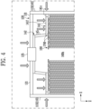
- FIG. 4 is a diagram for explaining a part of a battery cell according to an embodiment.
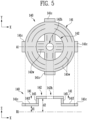
- FIG. 5 is a diagram for explaining a first current collector according to an embodiment.
- FIG. 5 illustrates a plan view of the XY plane for the first current collector, and a cross-sectional view of the XZ plane for portion A1.
- a battery cell 100 may include a can 110, a cap plate 120, a first current collector 140, and an electrode assembly 160.
- the electrode assembly 160 may be wound along a central axis.
- a central hole 160h may be formed in the central axis of the electrode assembly 160.
- a central hole 160h may be formed.
- the electrode assembly 160 may include a separator and an electrode.
- the electrode may include a flag 170f.
- the battery cell 100 may further include an electrolyte.
- the electrolyte may be, for example, a medium that transmits ions or current between the cathode and anode of the electrode assembly 160.
- the first current collector 140 may be disposed between the cap plate 120 and the electrode assembly 160.
- the first current collector 140 may be disposed below the cap plate 120 and above the electrode assembly 160.
- the first current collector 140 may be in contact with (or connected to) the flag 170f, the can 110, and the cap plate 120, respectively.
- the first current collector 140 may be welded to the flag 170f, the can 110, and the cap plate 120, respectively.
- the first current collector 140 may be welded while in contact with the flag 170f, the can 110, and the cap plate 120, respectively.
- various welding methods such as laser welding, resistance welding, ultrasonic welding, etc., may be performed.
- the first current collector 140 may include a first plate 141, a second plate 142, and a connecting part 145.
- the first plate 141, the second plate 142, and the connecting part 145 may be electrically connected to each other.
- the first plate 141 may be in contact with (or connected to) the flag 170f and the can 110, respectively.
- the first plate 141 may be welded to the flag 170f and the can 110, respectively.
- the first plate 141 may include a flag contact part 141f and a can contact part 141c.
- an upper end of the flag contact part 141f may be melted and solidified, so that the flag contact part 141f and the flag 170f may be welded.
- the inner end of the side part 113 may be melted and solidified, so that the can contact part 141c and the side part 113 of the can 110 may be welded.
- a beading part 115 may be formed on the side part 113 of the can 110.
- the can contact part 141c may be welded in a state of being in contact with the beading part 115.
- the can contact part 141c may be welded in a state of being in contact with an area of the side part 113 located at an upper end or a lower end of the beading part 115.
- the first plate 141 may be electrically connected to the flag 170f of the electrode 170.
- the first plate 141 may be electrically connected to the first flag 171f of the first electrode 171.
- the first plate 141 may be electrically connected to the can 110.
- a first welding part 141w may be formed on the first plate 141.
- the first welding part 141w may be an area welded to the flag 170f of the electrode assembly 160.
- the first welding part 141w may have a curved shape, but this is only an example, and may be transformed into various shapes such as a straight shape, but is not limited thereto.
- the second plate 142 may be in contact with (or connected to) the cap plate 120.
- the second plate 142 may be welded to the cap plate 120.
- an upper end of the cap plate 120 may be melted and solidified, so that the second plate 142 and the cap plate 120 are welded.
- the second plate 142 may be electrically connected to the cap plate 120.
- the second plate 142 at least one hole 142h may be formed.
- the hole 142h may be formed by penetrating through it.
- the number of holes 142h may be one or more.
- a hole that is connected to the hole 142h of the second plate 142 may be formed in the cap plate 120.
- An electrolyte may be injected into the inner space of the can 110 through the hole of the cap plate 120 and the hole 142h of the second plate 142.
- the second plate 142 may include an inner circumferential part with the hole 142h formed at the center, and an outer circumferential part located outside the inner circumferential part.
- the inner circumferential part may be a region surrounded by the outer circumferential part.
- the inner circumferential part may be formed in various shapes such as a square, a circle, an oval, etc.
- a second welding part 142w may be formed in the outer circumferential part.
- the second welding part 142w may be a region welded to the cap plate 120.
- the second welding part 142w may have a straight shape, but this is only an example, and may be transformed into various shapes such as a curved shape, but is not limited thereto.
- the hole 142h may be formed in the inner circumferential part or outer circumferential part.
- the connecting part 145 may connect the first plate 141 and the second plate 142.
- the connecting part 145 may extend in the height direction (e.g., the Z-axis direction).
- the connecting part 145 may extend in a state inclined with respect to the height direction (e.g., the Z-axis direction).
- the angle between the extension direction of the connecting part 145 and the height direction (e.g., the Z-axis direction) may be 0 degrees or more and less than 90 degrees.
- the first plate 141, the second plate 142, and the connecting part 145 may be formed integrally or formed separately.
- the polarity of each of the polar region 121 and the can 110 may be the same as the polarity of the flag 170f.
- the polarity may be one of (+) and (-) and may indicate a direction in which current flows.
- FIG. 6 is a diagram for explaining flow of heat within a battery cell according to an embodiment.
- the first plate 151 of the second current collector 150 may be welded to the flag 170f.
- the first plate 151 may be electrically connected to the flag 170f.
- the first plate 151 may be welded to the second flag 175f and electrically connected.
Landscapes
- Chemical & Material Sciences (AREA)
- Chemical Kinetics & Catalysis (AREA)
- Electrochemistry (AREA)
- General Chemical & Material Sciences (AREA)
- Engineering & Computer Science (AREA)
- Manufacturing & Machinery (AREA)
- Aviation & Aerospace Engineering (AREA)
- Connection Of Batteries Or Terminals (AREA)
Abstract
A battery cell of the present disclosure includes an electrode assembly in which an electrode including a flag and a separator are wound, a can accommodating the electrode assembly, a cap plate sealing the can, and a current collector disposed between the cap plate and the electrode assembly and in contact with the flag, the can, and the cap plate, respectively.
Description
- The present disclosure relates to a secondary battery, and more specifically, to a battery cell.
- An embodiment of the present disclosure is to provide a battery cell with improved stability.
- Secondary batteries may be reused multiple times by charging and discharging. The secondary batteries are widely used in various industries due to their economical and environmentally friendly characteristics. The secondary batteries may be classified into battery cells, battery modules, battery packs, and the like, depending on the unit. The battery module, the battery pack, and the like, may include multiple battery cells. In order to effectively dissipate heat of the battery cells, a method for adjusting the direction of heat movement is required. That is, the present inventors have found that the above problems may be solved by disposing the non-polar region where current does not flow at the center, the distance over which the heat moves may be shortened, the dissipation of the heat may be effectively controlled and the stability of a battery cell may be improved.
- The present disclosure may be widely applied in green technology fields such as solar power generation, wind power generation, etc. In addition, the present disclosure may be applied to eco-friendly devices such as electric vehicles, hybrid vehicles, etc., to prevent climate change by suppressing air pollution and greenhouse gas emissions.
- A battery cell according to an embodiment of the present disclosure may include an electrode assembly in which an electrode including a flag and a separator are wound, a can accommodating the electrode assembly, a cap plate sealing the can, and a current collector disposed between the cap plate and the electrode assembly and in contact with the flag, the can, and the cap plate, respectively.
- In an embodiment, the cap plate may include a non-polar region and a polar region located outside the non-polar region, and the current collector may be in contact with the polar region of the cap plate.
- In an embodiment, the non-polar region may include an insulating material that electrically separates it from the polar region.
- In an embodiment, polarity of each of the polar region and the can may be the same as polarity of the flag.
- In an embodiment, the current collector may include a first plate in contact with the flag and the can, respectively, a second plate in contact with the cap plate, and a connecting part connecting the first plate and the second plate.
- In an embodiment, a distance between the second plate and the electrode assembly may be greater than a distance between the first plate and the electrode assembly.
- In an embodiment, at least one hole may be formed in the second plate.
- In an embodiment, the second plate may include an inner circumferential part with a hole formed at center, and an outer circumferential part located outside the inner circumferential part.
- In an embodiment, the cap plate may include an insulating material inserted into the hole.
- In an embodiment, the battery cell may further include an electrode terminal located on an opposite side in a height direction from the cap plate.
- In an embodiment, the electrode terminal may be inserted into a penetration hole of the can.
- In an embodiment, the battery cell may further include an insulating gasket disposed between the can and the electrode terminal.
-
-
FIG. 1 is a diagram for explaining a battery cell according to an embodiment. -
FIGS. 2 and3 are diagrams for explaining an electrode assembly according to an embodiment. -
FIG. 4 is a diagram for explaining a part of a battery cell according to an embodiment. -
FIG. 5 is a diagram for explaining a first current collector according to an embodiment. -
FIG. 6 is a diagram for explaining flow of heat within a battery cell according to an embodiment. -
FIG. 7 is a diagram for explaining another part of a battery cell according to an embodiment. - The structural or functional descriptions of examples disclosed in the present specification or application are merely illustrated for the purpose of explaining examples according to the technical principle of the present invention, and examples according to the technical principle of the present invention may be implemented in various forms in addition to the examples disclosed in the specification of application. In addition, the technical principle of the present invention is not construed as being limited to the examples described in the present specification or application.
-
FIG. 1 is a diagram for explaining a battery cell according to an embodiment. - Referring to
FIG. 1 , abattery cell 100 according to an embodiment may include acan 110, acap plate 120, an electrode assembly, and a current collector. Thebattery cell 100 may be a secondary battery capable of being charged and discharged multiple times. For example, the secondary battery may be one of a lithium cobalt battery, a lithium high-nickel battery, a lithium iron phosphate battery, a lithium ion battery, a lithium polymer battery, a lithium sulfur battery, a nickel hydrogen battery, a nickel cadmium battery, a sodium battery, and an all-solid-state battery, but is not limited thereto and may be transformed into various types of secondary batteries. In an embodiment, thebattery cell 100 may further include anelectrode terminal 130. In an embodiment, thebattery cell 100 may further include aninsulating gasket 135. - The
can 110 may accommodate the electrode assembly. Thecan 110 may accommodate the current collector. For example, thecan 110 may have a shape of a container with a portion open. In an embodiment, thecan 110 may include a material such as various metals such as iron, aluminum, etc., alloys thereof, plastic, ceramic, or carbon. - In an embodiment, the
can 110 may include aflat part 111 and aside part 113. Theflat part 111 may extend from an upper end or a lower end of theside part 113. Here, each of the upper end and the lower end may be one of the end parts in a height direction (e.g., a Z-axis direction). For example, theflat part 111 may extend from the upper end of theside part 113. At least a portion of theflat part 111 may be formed as a flat surface with no height change in a horizontal direction (e.g., an X-axis direction, a Y-axis direction). The shape of the XY plane of theflat part 111 may be circular, but is not limited thereto and may be transformed into an oval, triangle, square, polygon, etc. Theside part 113 may be extended in the height direction (e.g., in the Z-axis direction) from the edge of theflat part 111. In an embodiment, theflat part 111 and theside part 113 may be formed integrally or formed separately from each other. - In an embodiment, a
beading part 115 may be formed in theside part 113. Thebeading part 115 may be a part in which theside part 113 is bent toward an inner space surrounded by theside part 113. In an embodiment, an opening part with one end open may be formed in thecan 110. The opening part may be formed on the opposite side of theflat part 111 in the height direction (e.g., in the Z-axis direction). For example, when theflat part 111 is formed at the upper end of theside part 113, the opening part may be formed at the lower end of theside part 113. The electrode assembly and the current collector may be inserted into the inner space of thecan 110 through the opening part. Thereafter, thebeading part 115 may be formed in one region of theside part 113 adj acent to the opening part. - The
cap plate 120 may seal thecan 110. In an embodiment, after the electrode assembly and the current collector are accommodated in the inner space of thecan 110, thecap plate 120 may be coupled to thecan 110. In other words, thecan 110 and thecap plate 120 may surround the outer side of the electrode assembly and the current collector. In an embodiment, the shapes of thecap plate 120 and thecan 110 coupled to each other may be cylindrical. However, this is only an example, and the shapes of thecap plate 120 and thecan 110 coupled to each other may be modified into various shapes such as a square or a hexahedron. In an embodiment, thecap plate 120 may be located on the opposite side of theflat part 111. For example, when theflat part 111 is formed at the upper end of theside part 113, thecap plate 120 may be coupled to the lower end of theside part 113. - In an embodiment, the current collector may include at least one of a first current collector and a second current collector. The first current collector may be disposed between the
cap plate 120 and the electrode assembly. The second current collector may be disposed between theflat part 111 of thecan 110 and the electrode assembly. - The current collector may be electrically connected to the electrode of the electrode assembly. To this end, the current collector may include a conductive material such as copper, gold, silver, aluminum, etc. The electrode may include a first electrode and a second electrode. In an embodiment, the first current collector and the second current collector may be electrically connected to different electrodes of the electrode assembly. For example, the first current collector may be connected to the first electrode, and the second current collector may be connected to the second electrode. In an embodiment, the first current collector may be electrically connected to the
can 110 and/or thecap plate 120. The second current collector may be electrically connected to theelectrode terminal 130. - In an embodiment, the
electrode terminal 130 may be located on the opposite side in the height direction (e.g., in the Z-axis direction) from thecap plate 120. Theelectrode terminal 130 may be electrically connected to an external device. In other words, current may flow to the external device through theelectrode terminal 130. - In an embodiment, the
electrode terminal 130 may be inserted into a penetration hole of thecan 110. In an embodiment, theelectrode terminal 130 may be a rivet. In an embodiment, the penetration hole may be formed in theflat part 111 of thecan 110. For example, the penetration hole may be formed by penetrating the center of theflat part 111. - In an embodiment, the insulating
gasket 135 may be disposed between thecan 110 and theelectrode terminal 130. For example, the insulatinggasket 135 may be disposed between theflat part 111 of thecan 110 and theelectrode terminal 130. The insulatinggasket 135 may include an insulating material. The insulating material may include a material having low electrical conductivity, such as polymer, ceramic, etc. -
FIGS. 2 and3 are diagrams for explaining an electrode assembly according to an embodiment. -
FIG. 2 is a partially disassembled view of a wound electrode assembly, andFIG. 3 illustrates an electrode assembly in which a flag is formed. - Referring to
FIGS. 2 and3 , anelectrode assembly 160 according to an embodiment may include anelectrode 170 and aseparator 180. - The
electrode 170 may include afirst electrode 171 and asecond electrode 175. Thefirst electrode 171 and thesecond electrode 175 may have different polarities. For example, thefirst electrode 171 may be an anode and thesecond electrode 175 may be a cathode. For another example, thefirst electrode 171 may be a cathode and thesecond electrode 175 may be an anode. - The
electrode 170 may be a plate on which an active material is applied to one region. In an embodiment, thefirst electrode 171 may include a firstuncoated part 171a on which a first active material is not applied, and a firstcoated part 171b on which the first active material is applied. Thesecond electrode 175 may include a seconduncoated part 175a on which a second active material is not applied, and a secondcoated part 175b on which the second active material is applied. In an embodiment, the firstuncoated part 171a may be formed at an upper end of the firstcoated part 171b. The seconduncoated part 175a may be formed at a lower end of the secondcoated part 175b. When thefirst electrode 171 is an anode, the first active material may be an anode active material. When thesecond electrode 175 is a cathode, the second active material may be a cathode active material. The cathode active material may include at least one of materials such as a lithium transition metal oxide, a nickel-cobalt-manganese lithium oxide, etc. The anode active material may include at least one of materials such as a carbon material, lithium, a lithium metal compound, silicon, a silicon compound, tin, a tin compound, etc. Meanwhile, the above-described embodiment is only an embodiment, and the cathode active material and the anode active material may be modified and implemented without limitation in type. - In an embodiment, the
electrode 170 may further include an insulatingcoating part 165 formed at the boundary between the uncoated part and the coated part. The insulatingcoating part 165 may include an insulating material. The insulatingcoating part 165 may improve the mechanical strength of the portion that is bent in the uncoated part to form aflag 170f. - The
separator 180 may include aninner separator 181 disposed between thefirst electrode 171 and thesecond electrode 175, and anouter separator 182 disposed on the outside. Theseparator 180 may include an insulating material. Theseparator 180 may block contact between thefirst electrode 171 and thesecond electrode 175, and electrically isolate thefirst electrode 171 and thesecond electrode 175. - The
electrode assembly 160 may be wound. In an embodiment, theelectrode 170 and theseparator 180 may be wound along the central axis (C) in a laminated state. Here, the central axis (C) may be in the height direction (e.g., the Z-axis direction). For example, theouter separator 182, thefirst electrode 171, theinner separator 181, and thesecond electrode 175 may be wound along the central axis (C) in a laminated state. - The
electrode 170 may include aflag 170f. In an embodiment, theflag 170f may be defined as a region from a bent portion to an end portion when a portion of the uncoated part is bent. In an embodiment, the uncoated part may be bent at an angle of 90 degrees or less with respect to the XY plane. In an embodiment, the uncoated part may be notched into a plurality of segments. The plurality of segments may be bent in the order of segments located inside to segments located outside among the plurality of segments. - The
flag 170f may include afirst flag 171f and asecond flag 175f. For example, thefirst flag 171f may be formed by bending the firstuncoated part 171a of thefirst electrode 171 in an inward direction toward the central axis (C). Thesecond flag 175f may be formed by bending the seconduncoated part 175a of thesecond electrode 175 in an inward direction toward the central axis (C). -
FIG. 4 is a diagram for explaining a part of a battery cell according to an embodiment.FIG. 5 is a diagram for explaining a first current collector according to an embodiment.FIG. 5 illustrates a plan view of the XY plane for the first current collector, and a cross-sectional view of the XZ plane for portion A1. - Referring to
FIGS. 1 and4 , abattery cell 100 according to an embodiment may include acan 110, acap plate 120, a firstcurrent collector 140, and anelectrode assembly 160. Theelectrode assembly 160 may be wound along a central axis. Acentral hole 160h may be formed in the central axis of theelectrode assembly 160. In the central axis of theelectrode assembly 160, acentral hole 160h may be formed. Theelectrode assembly 160 may include a separator and an electrode. The electrode may include aflag 170f. In an embodiment, thebattery cell 100 may further include an electrolyte. The electrolyte may be, for example, a medium that transmits ions or current between the cathode and anode of theelectrode assembly 160. - Referring to
FIGS. 4 and5 , the firstcurrent collector 140 may be disposed between thecap plate 120 and theelectrode assembly 160. For example, the firstcurrent collector 140 may be disposed below thecap plate 120 and above theelectrode assembly 160. - The first
current collector 140 may be in contact with (or connected to) theflag 170f, thecan 110, and thecap plate 120, respectively. For example, the firstcurrent collector 140 may be welded to theflag 170f, thecan 110, and thecap plate 120, respectively. In an embodiment, the firstcurrent collector 140 may be welded while in contact with theflag 170f, thecan 110, and thecap plate 120, respectively. At this time, various welding methods such as laser welding, resistance welding, ultrasonic welding, etc., may be performed. - The first
current collector 140 according to an embodiment may include afirst plate 141, asecond plate 142, and a connectingpart 145. Thefirst plate 141, thesecond plate 142, and the connectingpart 145 may be electrically connected to each other. - The
first plate 141 may be in contact with (or connected to) theflag 170f and thecan 110, respectively. For example, thefirst plate 141 may be welded to theflag 170f and thecan 110, respectively. In an embodiment, thefirst plate 141 may include aflag contact part 141f and a can contactpart 141c. For example, in a state where a lower end of theflag contact part 141f is in contact with an upper end of theflag 170f, an upper end of theflag contact part 141f may be melted and solidified, so that theflag contact part 141f and theflag 170f may be welded. In a state where the outer end of the can contactpart 141c is in contact with the inner end of aside part 113 of thecan 110, the inner end of theside part 113 may be melted and solidified, so that the can contactpart 141c and theside part 113 of thecan 110 may be welded. In an embodiment, referring also toFIG. 1 , abeading part 115 may be formed on theside part 113 of thecan 110. In this case, the can contactpart 141c may be welded in a state of being in contact with thebeading part 115. As another example, the can contactpart 141c may be welded in a state of being in contact with an area of theside part 113 located at an upper end or a lower end of thebeading part 115. - The
first plate 141 may be electrically connected to theflag 170f of theelectrode 170. For example, referring toFIGS. 2 and3 together, thefirst plate 141 may be electrically connected to thefirst flag 171f of thefirst electrode 171. In an embodiment, thefirst plate 141 may be electrically connected to thecan 110. - On the
first plate 141, afirst welding part 141w may be formed. Thefirst welding part 141w may be an area welded to theflag 170f of theelectrode assembly 160. Thefirst welding part 141w may have a curved shape, but this is only an example, and may be transformed into various shapes such as a straight shape, but is not limited thereto. - The
second plate 142 may be in contact with (or connected to) thecap plate 120. For example, thesecond plate 142 may be welded to thecap plate 120. Specifically, in a state where an upper end of thesecond plate 142 is in contact with a lower end of thecap plate 120, an upper end of thecap plate 120 may be melted and solidified, so that thesecond plate 142 and thecap plate 120 are welded. - The
second plate 142 may be electrically connected to thecap plate 120. - In an embodiment, in the
second plate 142, at least onehole 142h may be formed. Thehole 142h may be formed by penetrating through it. The number ofholes 142h may be one or more. In an embodiment, in thecap plate 120, a hole that is connected to thehole 142h of thesecond plate 142 may be formed. An electrolyte may be injected into the inner space of thecan 110 through the hole of thecap plate 120 and thehole 142h of thesecond plate 142. - In an embodiment, the
second plate 142 may include an inner circumferential part with thehole 142h formed at the center, and an outer circumferential part located outside the inner circumferential part. The inner circumferential part may be a region surrounded by the outer circumferential part. The inner circumferential part may be formed in various shapes such as a square, a circle, an oval, etc. In the outer circumferential part, asecond welding part 142w may be formed. Thesecond welding part 142w may be a region welded to thecap plate 120. Thesecond welding part 142w may have a straight shape, but this is only an example, and may be transformed into various shapes such as a curved shape, but is not limited thereto. Thehole 142h may be formed in the inner circumferential part or outer circumferential part. - The connecting
part 145 may connect thefirst plate 141 and thesecond plate 142. For example, the connectingpart 145 may extend in the height direction (e.g., the Z-axis direction). In an embodiment, the connectingpart 145 may extend in a state inclined with respect to the height direction (e.g., the Z-axis direction). In this case, the angle between the extension direction of the connectingpart 145 and the height direction (e.g., the Z-axis direction) may be 0 degrees or more and less than 90 degrees. Thefirst plate 141, thesecond plate 142, and the connectingpart 145 may be formed integrally or formed separately. - In an embodiment, the distance (d2) between the
second plate 142 and the reference location (R1) may be greater than the distance (d1) between thefirst plate 141 and the reference location (R1). In an embodiment, the reference location (R1) may be an end part of theelectrode assembly 160 with respect to the height direction (e.g., the Z-axis direction). For example, the reference location (R1) may be an end part of theflag 170f. In other words, an open space may be formed between thesecond plate 142 and theelectrode assembly 160. The impregnation property of the electrolyte may be improved through the open space. - In an embodiment, the
cap plate 120 may include an insulating material. The insulating material may be inserted into the hole of thecap plate 120. The insulating material may include a material having low electrical conductivity, such as a polymer, ceramic, etc. The insulating material may correspond to at least a portion of anon-polar region 125. - In an embodiment, the
cap plate 120 may include apolar region 121 and anon-polar region 125. Thepolar region 121 may be located outside thenon-polar region 125. For example, thenon-polar region 125 may be located at the center of thecap plate 120. - In an embodiment, the
non-polar region 125 may include an insulating material that electrically separates it from thepolar region 121. The insulating material may include a material with low electrical conductivity, such as a polymer, ceramic, etc. Thepolar region 121 may be a region through which current may flow, and thenon-polar region 125 may be a region through which current may not flow. In an embodiment, thenon-polar region 125 may protrude in the height direction (e.g., in the Z-axis direction) greater than thepolar region 121. - In an embodiment, the polarity of each of the
polar region 121 and thecan 110 may be the same as the polarity of theflag 170f. For example, the polarity may be one of (+) and (-) and may indicate a direction in which current flows. - In an embodiment, the first
current collector 140 may be in contact with (or connected to) thepolarity region 121 of thecap plate 120. For example, the firstcurrent collector 140 may be welded to thepolarity region 121 of thecap plate 120. Specifically, thesecond plate 142 of the firstcurrent collector 140 may be welded in a state of being in contact with thecap plate 120. -
FIG. 6 is a diagram for explaining flow of heat within a battery cell according to an embodiment. - Referring to
FIGS. 4 and6 , heat generated in theflag 170f according to an embodiment may be dissipated to the outside via theside part 113 of thecan 110 through thefirst plate 141 of the firstcurrent collector 140. According to an embodiment of the present disclosure, heat generated from theflag 170f may be dissipated to the outside along thepolar region 121 of thecap plate 120 through thefirst plate 141, the connectingpart 145, and thesecond plate 142. According to an embodiment, heat may be generated in a region where current flows. By disposing thenon-polar region 125 where current does not flow at the center, the distance over which the heat moves may be shortened, and the dissipation of the heat may be effectively controlled. -
FIG. 7 is a diagram for explaining another part of a battery cell according to an embodiment.FIG. 7 illustrates an opposite portion in the height direction of the battery cell ofFIG. 5 . - Referring to
FIG. 1 andFIG. 7 , thebattery cell 100 may include acan 110, a secondcurrent collector 150, and anelectrode assembly 160. Theelectrode assembly 160 may be wound along a central axis. Theelectrode assembly 160 may include a separator and an electrode. The electrode may include aflag 170f. In an embodiment, thebattery cell 100 may further include an electrolyte. The electrolyte may be, for example, a medium that transfers ions or current between the cathode and anode of theelectrode assembly 160. - The second
current collector 150 may be electrically connected to theflag 170f of theelectrode 170. For example, referring toFIGS. 2 and3 together, the secondcurrent collector 150 may be electrically connected to thesecond flag 175f of thesecond electrode 175. In an embodiment, the secondcurrent collector 150 may be electrically connected to theelectrode terminal 130. - The second
current collector 150 according to an embodiment may include afirst plate 151, asecond plate 152, and a connectingpart 155. The connectingpart 155 may connect thefirst plate 151 and thesecond plate 152. Thefirst plate 151, thesecond plate 152, and the connectingpart 155 may be electrically connected to each other. - The
first plate 151 of the secondcurrent collector 150 may be welded to theflag 170f. Thefirst plate 151 may be electrically connected to theflag 170f. For example, thefirst plate 151 may be welded to thesecond flag 175f and electrically connected. - The
second plate 152 of the secondcurrent collector 150 may be welded to theelectrode terminal 130. Thesecond plate 152 may be electrically connected to theelectrode terminal 130. - In an embodiment, the insulating
gasket 135 may be disposed between theflat part 111 of thecan 110 and theelectrode terminal 130. The insulatinggasket 135 may block contact between theelectrode terminal 130 and thecan 110. The insulatinggasket 135 may electrically isolate theelectrode terminal 130 and thecan 110. In other words, theelectrode terminal 130 and thecan 110 may have different polarities. For example, if the polarity of theelectrode terminal 130 is (+), the polarity of thecan 110 may be (-).
Claims (12)
- A battery cell comprising:an electrode assembly in which an electrode comprising a flag and a separator are wound;a can accommodating the electrode assembly;a cap plate sealing the can; anda current collector disposed between the cap plate and the electrode assembly and in contact with the flag, the can, and the cap plate, respectively.
- The battery cell according to claim 1, wherein the cap plate comprises a non-polar region and a polar region located outside the non-polar region, and
the current collector is in contact with the polar region of the cap plate. - The battery cell according to claim 2, wherein the non-polar region comprises an insulating material that electrically separates it from the polar region.
- The battery cell according to claim 2 or 3, wherein polarity of each of the polar region and the can is the same as polarity of the flag.
- The battery cell according to any one of claims 1 to 4, wherein the current collector comprises:a first plate in contact with the flag and the can, respectively;a second plate in contact with the cap plate; anda connecting part connecting the first plate and the second plate.
- The battery cell according to claim 5, wherein a distance between the second plate and the electrode assembly is greater than a distance between the first plate and the electrode assembly.
- The battery cell according to claim 5, wherein at least one hole is formed in the second plate.
- The battery cell according to claim 5, wherein the second plate comprises an inner circumferential part with a hole formed at center, and an outer circumferential part located outside the inner circumferential part.
- The battery cell according to claim 8, wherein the cap plate comprises an insulating material inserted into the hole.
- The battery cell according to any one of claims 1 to 9, further comprising an electrode terminal located on an opposite side in a height direction from the cap plate.
- The battery cell according to claim 10, wherein the electrode terminal is inserted into a penetration hole of the can.
- The battery cell according to claim 10, further comprising an insulating gasket disposed between the can and the electrode terminal.
Applications Claiming Priority (3)
| Application Number | Priority Date | Filing Date | Title |
|---|---|---|---|
| KR20230188426 | 2023-12-21 | ||
| KR20240002240 | 2024-01-05 | ||
| KR1020240049520A KR20250097620A (en) | 2023-12-21 | 2024-04-12 | Battery cell |
Publications (1)
| Publication Number | Publication Date |
|---|---|
| EP4576295A1 true EP4576295A1 (en) | 2025-06-25 |
Family
ID=93926194
Family Applications (1)
| Application Number | Title | Priority Date | Filing Date |
|---|---|---|---|
| EP24221944.2A Pending EP4576295A1 (en) | 2023-12-21 | 2024-12-19 | Battery cell |
Country Status (3)
| Country | Link |
|---|---|
| US (1) | US20250210825A1 (en) |
| EP (1) | EP4576295A1 (en) |
| CN (1) | CN120199957A (en) |
Citations (4)
| Publication number | Priority date | Publication date | Assignee | Title |
|---|---|---|---|---|
| CN112909445A (en) * | 2021-01-26 | 2021-06-04 | 苏州宇量电池有限公司 | Single-head bipolar multi-tab cylindrical lithium ion battery |
| CN115117524A (en) * | 2022-07-04 | 2022-09-27 | 中创新航科技股份有限公司 | Battery and method for manufacturing battery |
| EP4152493A1 (en) * | 2021-05-21 | 2023-03-22 | Eve Power Co., Ltd. | Cylindrical battery |
| CN219203322U (en) * | 2022-12-29 | 2023-06-16 | 远景动力技术(江苏)有限公司 | A cylindrical battery and electronic equipment |
-
2024
- 2024-12-19 EP EP24221944.2A patent/EP4576295A1/en active Pending
- 2024-12-20 CN CN202411889650.6A patent/CN120199957A/en active Pending
- 2024-12-20 US US18/989,009 patent/US20250210825A1/en active Pending
Patent Citations (6)
| Publication number | Priority date | Publication date | Assignee | Title |
|---|---|---|---|---|
| CN112909445A (en) * | 2021-01-26 | 2021-06-04 | 苏州宇量电池有限公司 | Single-head bipolar multi-tab cylindrical lithium ion battery |
| EP4152493A1 (en) * | 2021-05-21 | 2023-03-22 | Eve Power Co., Ltd. | Cylindrical battery |
| CN115117524A (en) * | 2022-07-04 | 2022-09-27 | 中创新航科技股份有限公司 | Battery and method for manufacturing battery |
| US20240006694A1 (en) * | 2022-07-04 | 2024-01-04 | Calb Co., Ltd. | Battery and manufacturing method for battery |
| CN219203322U (en) * | 2022-12-29 | 2023-06-16 | 远景动力技术(江苏)有限公司 | A cylindrical battery and electronic equipment |
| US20240222754A1 (en) * | 2022-12-29 | 2024-07-04 | Aesc Japan Ltd. | Cylindrical battery and electronic device |
Also Published As
| Publication number | Publication date |
|---|---|
| US20250210825A1 (en) | 2025-06-26 |
| CN120199957A (en) | 2025-06-24 |
Similar Documents
| Publication | Publication Date | Title |
|---|---|---|
| US20250105478A1 (en) | Secondary battery | |
| KR101146414B1 (en) | Rechargeable battery | |
| KR102885306B1 (en) | Rechargeable battery | |
| US20220200108A1 (en) | Secondary battery | |
| KR101222247B1 (en) | Secondary battery | |
| KR20250028320A (en) | Secondary battery having symmetrical multi-tap | |
| KR20120010092A (en) | Secondary battery | |
| KR20230089196A (en) | Secondary Battery | |
| US10256457B2 (en) | Secondary battery | |
| US10181596B2 (en) | Secondary Battery | |
| KR102467767B1 (en) | A secondary battery | |
| KR101233514B1 (en) | Secondary battery | |
| US20140023913A1 (en) | Prismatic secondary battery | |
| KR101233535B1 (en) | Secondary battery | |
| US11011809B2 (en) | Rechargeable battery | |
| US20250210825A1 (en) | Battery Cell | |
| KR20250097620A (en) | Battery cell | |
| US20260018652A1 (en) | Electrode assembly and battery cell including the same | |
| EP4693551A2 (en) | Sub plate assembly and secondary battery including the same | |
| KR101222244B1 (en) | Secondary battery | |
| EP4693705A1 (en) | Battery cell | |
| EP4693704A1 (en) | Battery cell | |
| US20240405386A1 (en) | Secondary battery | |
| EP4589696A1 (en) | Secondary battery and method of manufacturing secondary battery | |
| US20250343330A1 (en) | Battery cell |
Legal Events
| Date | Code | Title | Description |
|---|---|---|---|
| PUAI | Public reference made under article 153(3) epc to a published international application that has entered the european phase |
Free format text: ORIGINAL CODE: 0009012 |
|
| STAA | Information on the status of an ep patent application or granted ep patent |
Free format text: STATUS: REQUEST FOR EXAMINATION WAS MADE |
|
| 17P | Request for examination filed |
Effective date: 20241219 |
|
| AK | Designated contracting states |
Kind code of ref document: A1 Designated state(s): AL AT BE BG CH CY CZ DE DK EE ES FI FR GB GR HR HU IE IS IT LI LT LU LV MC ME MK MT NL NO PL PT RO RS SE SI SK SM TR |